EP3684661B1 - Elektromechanisches bremsssystem für fahrzeuge, ausgestattet mit elektrischer betätigung und elektrischer rückfallebene - Google Patents
Elektromechanisches bremsssystem für fahrzeuge, ausgestattet mit elektrischer betätigung und elektrischer rückfallebene Download PDFInfo
- Publication number
- EP3684661B1 EP3684661B1 EP18783571.5A EP18783571A EP3684661B1 EP 3684661 B1 EP3684661 B1 EP 3684661B1 EP 18783571 A EP18783571 A EP 18783571A EP 3684661 B1 EP3684661 B1 EP 3684661B1
- Authority
- EP
- European Patent Office
- Prior art keywords
- braking
- brake
- brake group
- fault
- vehicles
- Prior art date
- Legal status (The legal status is an assumption and is not a legal conclusion. Google has not performed a legal analysis and makes no representation as to the accuracy of the status listed.)
- Active
Links
- 238000010248 power generation Methods 0.000 claims description 3
- 230000007257 malfunction Effects 0.000 description 5
- 230000005540 biological transmission Effects 0.000 description 4
- 239000012530 fluid Substances 0.000 description 3
- 230000001172 regenerating effect Effects 0.000 description 3
- HBBGRARXTFLTSG-UHFFFAOYSA-N Lithium ion Chemical compound [Li+] HBBGRARXTFLTSG-UHFFFAOYSA-N 0.000 description 1
- 230000000694 effects Effects 0.000 description 1
- 230000008030 elimination Effects 0.000 description 1
- 238000003379 elimination reaction Methods 0.000 description 1
- 229910001416 lithium ion Inorganic materials 0.000 description 1
- 238000012423 maintenance Methods 0.000 description 1
- 238000012986 modification Methods 0.000 description 1
- 230000004048 modification Effects 0.000 description 1
- 238000007789 sealing Methods 0.000 description 1
Images

Classifications
-
- B—PERFORMING OPERATIONS; TRANSPORTING
- B60—VEHICLES IN GENERAL
- B60T—VEHICLE BRAKE CONTROL SYSTEMS OR PARTS THEREOF; BRAKE CONTROL SYSTEMS OR PARTS THEREOF, IN GENERAL; ARRANGEMENT OF BRAKING ELEMENTS ON VEHICLES IN GENERAL; PORTABLE DEVICES FOR PREVENTING UNWANTED MOVEMENT OF VEHICLES; VEHICLE MODIFICATIONS TO FACILITATE COOLING OF BRAKES
- B60T8/00—Arrangements for adjusting wheel-braking force to meet varying vehicular or ground-surface conditions, e.g. limiting or varying distribution of braking force
- B60T8/32—Arrangements for adjusting wheel-braking force to meet varying vehicular or ground-surface conditions, e.g. limiting or varying distribution of braking force responsive to a speed condition, e.g. acceleration or deceleration
- B60T8/88—Arrangements for adjusting wheel-braking force to meet varying vehicular or ground-surface conditions, e.g. limiting or varying distribution of braking force responsive to a speed condition, e.g. acceleration or deceleration with failure responsive means, i.e. means for detecting and indicating faulty operation of the speed responsive control means
- B60T8/92—Arrangements for adjusting wheel-braking force to meet varying vehicular or ground-surface conditions, e.g. limiting or varying distribution of braking force responsive to a speed condition, e.g. acceleration or deceleration with failure responsive means, i.e. means for detecting and indicating faulty operation of the speed responsive control means automatically taking corrective action
-
- B—PERFORMING OPERATIONS; TRANSPORTING
- B60—VEHICLES IN GENERAL
- B60T—VEHICLE BRAKE CONTROL SYSTEMS OR PARTS THEREOF; BRAKE CONTROL SYSTEMS OR PARTS THEREOF, IN GENERAL; ARRANGEMENT OF BRAKING ELEMENTS ON VEHICLES IN GENERAL; PORTABLE DEVICES FOR PREVENTING UNWANTED MOVEMENT OF VEHICLES; VEHICLE MODIFICATIONS TO FACILITATE COOLING OF BRAKES
- B60T8/00—Arrangements for adjusting wheel-braking force to meet varying vehicular or ground-surface conditions, e.g. limiting or varying distribution of braking force
- B60T8/32—Arrangements for adjusting wheel-braking force to meet varying vehicular or ground-surface conditions, e.g. limiting or varying distribution of braking force responsive to a speed condition, e.g. acceleration or deceleration
- B60T8/88—Arrangements for adjusting wheel-braking force to meet varying vehicular or ground-surface conditions, e.g. limiting or varying distribution of braking force responsive to a speed condition, e.g. acceleration or deceleration with failure responsive means, i.e. means for detecting and indicating faulty operation of the speed responsive control means
- B60T8/885—Arrangements for adjusting wheel-braking force to meet varying vehicular or ground-surface conditions, e.g. limiting or varying distribution of braking force responsive to a speed condition, e.g. acceleration or deceleration with failure responsive means, i.e. means for detecting and indicating faulty operation of the speed responsive control means using electrical circuitry
-
- B—PERFORMING OPERATIONS; TRANSPORTING
- B60—VEHICLES IN GENERAL
- B60T—VEHICLE BRAKE CONTROL SYSTEMS OR PARTS THEREOF; BRAKE CONTROL SYSTEMS OR PARTS THEREOF, IN GENERAL; ARRANGEMENT OF BRAKING ELEMENTS ON VEHICLES IN GENERAL; PORTABLE DEVICES FOR PREVENTING UNWANTED MOVEMENT OF VEHICLES; VEHICLE MODIFICATIONS TO FACILITATE COOLING OF BRAKES
- B60T13/00—Transmitting braking action from initiating means to ultimate brake actuator with power assistance or drive; Brake systems incorporating such transmitting means, e.g. air-pressure brake systems
- B60T13/10—Transmitting braking action from initiating means to ultimate brake actuator with power assistance or drive; Brake systems incorporating such transmitting means, e.g. air-pressure brake systems with fluid assistance, drive, or release
- B60T13/66—Electrical control in fluid-pressure brake systems
- B60T13/662—Electrical control in fluid-pressure brake systems characterised by specified functions of the control system components
-
- B—PERFORMING OPERATIONS; TRANSPORTING
- B60—VEHICLES IN GENERAL
- B60T—VEHICLE BRAKE CONTROL SYSTEMS OR PARTS THEREOF; BRAKE CONTROL SYSTEMS OR PARTS THEREOF, IN GENERAL; ARRANGEMENT OF BRAKING ELEMENTS ON VEHICLES IN GENERAL; PORTABLE DEVICES FOR PREVENTING UNWANTED MOVEMENT OF VEHICLES; VEHICLE MODIFICATIONS TO FACILITATE COOLING OF BRAKES
- B60T17/00—Component parts, details, or accessories of power brake systems not covered by groups B60T8/00, B60T13/00 or B60T15/00, or presenting other characteristic features
- B60T17/18—Safety devices; Monitoring
- B60T17/22—Devices for monitoring or checking brake systems; Signal devices
- B60T17/221—Procedure or apparatus for checking or keeping in a correct functioning condition of brake systems
-
- B—PERFORMING OPERATIONS; TRANSPORTING
- B60—VEHICLES IN GENERAL
- B60T—VEHICLE BRAKE CONTROL SYSTEMS OR PARTS THEREOF; BRAKE CONTROL SYSTEMS OR PARTS THEREOF, IN GENERAL; ARRANGEMENT OF BRAKING ELEMENTS ON VEHICLES IN GENERAL; PORTABLE DEVICES FOR PREVENTING UNWANTED MOVEMENT OF VEHICLES; VEHICLE MODIFICATIONS TO FACILITATE COOLING OF BRAKES
- B60T8/00—Arrangements for adjusting wheel-braking force to meet varying vehicular or ground-surface conditions, e.g. limiting or varying distribution of braking force
- B60T8/17—Using electrical or electronic regulation means to control braking
-
- B—PERFORMING OPERATIONS; TRANSPORTING
- B60—VEHICLES IN GENERAL
- B60T—VEHICLE BRAKE CONTROL SYSTEMS OR PARTS THEREOF; BRAKE CONTROL SYSTEMS OR PARTS THEREOF, IN GENERAL; ARRANGEMENT OF BRAKING ELEMENTS ON VEHICLES IN GENERAL; PORTABLE DEVICES FOR PREVENTING UNWANTED MOVEMENT OF VEHICLES; VEHICLE MODIFICATIONS TO FACILITATE COOLING OF BRAKES
- B60T8/00—Arrangements for adjusting wheel-braking force to meet varying vehicular or ground-surface conditions, e.g. limiting or varying distribution of braking force
- B60T8/32—Arrangements for adjusting wheel-braking force to meet varying vehicular or ground-surface conditions, e.g. limiting or varying distribution of braking force responsive to a speed condition, e.g. acceleration or deceleration
- B60T8/321—Arrangements for adjusting wheel-braking force to meet varying vehicular or ground-surface conditions, e.g. limiting or varying distribution of braking force responsive to a speed condition, e.g. acceleration or deceleration deceleration
- B60T8/3255—Systems in which the braking action is dependent on brake pedal data
-
- B—PERFORMING OPERATIONS; TRANSPORTING
- B60—VEHICLES IN GENERAL
- B60T—VEHICLE BRAKE CONTROL SYSTEMS OR PARTS THEREOF; BRAKE CONTROL SYSTEMS OR PARTS THEREOF, IN GENERAL; ARRANGEMENT OF BRAKING ELEMENTS ON VEHICLES IN GENERAL; PORTABLE DEVICES FOR PREVENTING UNWANTED MOVEMENT OF VEHICLES; VEHICLE MODIFICATIONS TO FACILITATE COOLING OF BRAKES
- B60T8/00—Arrangements for adjusting wheel-braking force to meet varying vehicular or ground-surface conditions, e.g. limiting or varying distribution of braking force
- B60T8/32—Arrangements for adjusting wheel-braking force to meet varying vehicular or ground-surface conditions, e.g. limiting or varying distribution of braking force responsive to a speed condition, e.g. acceleration or deceleration
- B60T8/34—Arrangements for adjusting wheel-braking force to meet varying vehicular or ground-surface conditions, e.g. limiting or varying distribution of braking force responsive to a speed condition, e.g. acceleration or deceleration having a fluid pressure regulator responsive to a speed condition
- B60T8/36—Arrangements for adjusting wheel-braking force to meet varying vehicular or ground-surface conditions, e.g. limiting or varying distribution of braking force responsive to a speed condition, e.g. acceleration or deceleration having a fluid pressure regulator responsive to a speed condition including a pilot valve responding to an electromagnetic force
-
- B—PERFORMING OPERATIONS; TRANSPORTING
- B62—LAND VEHICLES FOR TRAVELLING OTHERWISE THAN ON RAILS
- B62D—MOTOR VEHICLES; TRAILERS
- B62D6/00—Arrangements for automatically controlling steering depending on driving conditions sensed and responded to, e.g. control circuits
-
- B—PERFORMING OPERATIONS; TRANSPORTING
- B60—VEHICLES IN GENERAL
- B60T—VEHICLE BRAKE CONTROL SYSTEMS OR PARTS THEREOF; BRAKE CONTROL SYSTEMS OR PARTS THEREOF, IN GENERAL; ARRANGEMENT OF BRAKING ELEMENTS ON VEHICLES IN GENERAL; PORTABLE DEVICES FOR PREVENTING UNWANTED MOVEMENT OF VEHICLES; VEHICLE MODIFICATIONS TO FACILITATE COOLING OF BRAKES
- B60T2260/00—Interaction of vehicle brake system with other systems
- B60T2260/02—Active Steering, Steer-by-Wire
-
- B—PERFORMING OPERATIONS; TRANSPORTING
- B60—VEHICLES IN GENERAL
- B60T—VEHICLE BRAKE CONTROL SYSTEMS OR PARTS THEREOF; BRAKE CONTROL SYSTEMS OR PARTS THEREOF, IN GENERAL; ARRANGEMENT OF BRAKING ELEMENTS ON VEHICLES IN GENERAL; PORTABLE DEVICES FOR PREVENTING UNWANTED MOVEMENT OF VEHICLES; VEHICLE MODIFICATIONS TO FACILITATE COOLING OF BRAKES
- B60T2270/00—Further aspects of brake control systems not otherwise provided for
- B60T2270/30—ESP control system
-
- B—PERFORMING OPERATIONS; TRANSPORTING
- B60—VEHICLES IN GENERAL
- B60T—VEHICLE BRAKE CONTROL SYSTEMS OR PARTS THEREOF; BRAKE CONTROL SYSTEMS OR PARTS THEREOF, IN GENERAL; ARRANGEMENT OF BRAKING ELEMENTS ON VEHICLES IN GENERAL; PORTABLE DEVICES FOR PREVENTING UNWANTED MOVEMENT OF VEHICLES; VEHICLE MODIFICATIONS TO FACILITATE COOLING OF BRAKES
- B60T2270/00—Further aspects of brake control systems not otherwise provided for
- B60T2270/40—Failsafe aspects of brake control systems
- B60T2270/402—Back-up
-
- B—PERFORMING OPERATIONS; TRANSPORTING
- B60—VEHICLES IN GENERAL
- B60T—VEHICLE BRAKE CONTROL SYSTEMS OR PARTS THEREOF; BRAKE CONTROL SYSTEMS OR PARTS THEREOF, IN GENERAL; ARRANGEMENT OF BRAKING ELEMENTS ON VEHICLES IN GENERAL; PORTABLE DEVICES FOR PREVENTING UNWANTED MOVEMENT OF VEHICLES; VEHICLE MODIFICATIONS TO FACILITATE COOLING OF BRAKES
- B60T2270/00—Further aspects of brake control systems not otherwise provided for
- B60T2270/40—Failsafe aspects of brake control systems
- B60T2270/404—Brake-by-wire or X-by-wire failsafe
-
- B—PERFORMING OPERATIONS; TRANSPORTING
- B60—VEHICLES IN GENERAL
- B60T—VEHICLE BRAKE CONTROL SYSTEMS OR PARTS THEREOF; BRAKE CONTROL SYSTEMS OR PARTS THEREOF, IN GENERAL; ARRANGEMENT OF BRAKING ELEMENTS ON VEHICLES IN GENERAL; PORTABLE DEVICES FOR PREVENTING UNWANTED MOVEMENT OF VEHICLES; VEHICLE MODIFICATIONS TO FACILITATE COOLING OF BRAKES
- B60T2270/00—Further aspects of brake control systems not otherwise provided for
- B60T2270/60—Regenerative braking
-
- B—PERFORMING OPERATIONS; TRANSPORTING
- B60—VEHICLES IN GENERAL
- B60T—VEHICLE BRAKE CONTROL SYSTEMS OR PARTS THEREOF; BRAKE CONTROL SYSTEMS OR PARTS THEREOF, IN GENERAL; ARRANGEMENT OF BRAKING ELEMENTS ON VEHICLES IN GENERAL; PORTABLE DEVICES FOR PREVENTING UNWANTED MOVEMENT OF VEHICLES; VEHICLE MODIFICATIONS TO FACILITATE COOLING OF BRAKES
- B60T2270/00—Further aspects of brake control systems not otherwise provided for
- B60T2270/82—Brake-by-Wire, EHB
-
- B—PERFORMING OPERATIONS; TRANSPORTING
- B60—VEHICLES IN GENERAL
- B60T—VEHICLE BRAKE CONTROL SYSTEMS OR PARTS THEREOF; BRAKE CONTROL SYSTEMS OR PARTS THEREOF, IN GENERAL; ARRANGEMENT OF BRAKING ELEMENTS ON VEHICLES IN GENERAL; PORTABLE DEVICES FOR PREVENTING UNWANTED MOVEMENT OF VEHICLES; VEHICLE MODIFICATIONS TO FACILITATE COOLING OF BRAKES
- B60T7/00—Brake-action initiating means
- B60T7/02—Brake-action initiating means for personal initiation
- B60T7/04—Brake-action initiating means for personal initiation foot actuated
- B60T7/042—Brake-action initiating means for personal initiation foot actuated by electrical means, e.g. using travel or force sensors
-
- B—PERFORMING OPERATIONS; TRANSPORTING
- B60—VEHICLES IN GENERAL
- B60T—VEHICLE BRAKE CONTROL SYSTEMS OR PARTS THEREOF; BRAKE CONTROL SYSTEMS OR PARTS THEREOF, IN GENERAL; ARRANGEMENT OF BRAKING ELEMENTS ON VEHICLES IN GENERAL; PORTABLE DEVICES FOR PREVENTING UNWANTED MOVEMENT OF VEHICLES; VEHICLE MODIFICATIONS TO FACILITATE COOLING OF BRAKES
- B60T7/00—Brake-action initiating means
- B60T7/02—Brake-action initiating means for personal initiation
- B60T7/08—Brake-action initiating means for personal initiation hand actuated
- B60T7/085—Brake-action initiating means for personal initiation hand actuated by electrical means, e.g. travel, force sensors
Definitions
- the present invention relates to a brake by wire braking system for vehicles, provided with both electric actuation and with electric back-up.
- the present invention relates to the field of brake by wire braking systems for vehicles.
- Autonomous braking systems are also known in which the steering system of the vehicle decides the timing and the amount of braking and consequently actuates said electromechanical means connected to the braking devices.
- braking systems must provide a back-up strategy to be implemented in the event of an electrical fault of at least one device.
- brake-by-wire braking systems are known, for example, in which, in the event of an electrical fault, the braking action is exerted mechanically, conventionally, i.e. by fluidly connecting the lever or pedal operated by the user to request the braking action, directly with said braking devices.
- hydraulic back-up solutions are not applicable to self-driving vehicles and do not always guarantee maximum braking efficiency in the event of hydraulic back-up.
- a braking system for vehicles comprising
- each control device is programmed so as to be able to switch from a standard mode to a degraded one in the event of a fault.
- all the control units are operatively connected to each other so that each knows the type of operation, standard or fault, implemented by each of the other control units.
- each electromechanical or electro-hydraulic actuator is equipped with an operating sensor suitable to monitor the operating condition of the relative electromechanical or electro-hydraulic actuator and/or of the relative braking device and to send the corresponding control unit an indication of standard or fault operation.
- the electromechanical actuators comprise a three-phase motor, each three-phase motor being operatively connected to the respective control device and to the respective power source of the corresponding brake group.
- control units are programmed so that in case of fault of a brake group, the actuation of the remaining brake groups is ensured so that:
- the two front brake groups are actuated and, progressively, the remaining rear brake group so as to allow the dynamic control of the vehicle
- the other front brake group is actuated and the corresponding crossover rear brake group, i.e. arranged on the opposite side to the functioning front brake group and, progressively, the remaining rear brake group, on the same side as the functioning front brake group.
- control units are programmed so that in case of fault of a brake group, the actuation of the remaining three brake groups is ensured
- the braking system is operatively connected to a steering mechanism of the vehicle, so as to coordinate the operation of steering mechanism with the actuation of the functioning brake groups.
- control units are programmed so that in case of fault of a brake group, the actuation of the remaining three brake groups is ensured, wherein the braking system is operatively connected to electrical power generation means operatively connected to the brake groups so as to obtain an additional braking action of the vehicle.
- each control unit of a brake group of an axle is operatively connected to both a primary control device connected to the brake group thereof and to a secondary control device connected to the other brake group of the same axle, so that, in the case of standard operation, each braking device is actuated by its own primary control device and, in case of electric fault of a brake group, the braking device of the brake group in fault is actuated by the secondary control device controlled by the other control unit of the axle.
- each control unit of a brake group of a front or rear axle is operatively connected both to a primary piloting device and to a secondary piloting device, wherein each of said primary and secondary piloting devices is operatively connected to the brake groups of the same axle, so that, in the case of standard operation, each braking device is actuated by at least one or both of said primary and secondary piloting devices and, in the event of an electrical fault, the braking device of the faulted brake group is actuated by the other piloting device.
- said axle is the front axle or rear axle of the vehicle.
- all the control units are operatively connected to each other so that each knows the type of operation, standard or fault, implemented by each of the other control units.
- each electromechanical actuator is equipped with two operating sensors, each suitable to monitor the operating condition of the relative electromechanical actuator and/or of the relative braking device and to send an indication of standard or fault operation to both the control units of the same axle.
- the electromechanical actuators comprise a six-phase motor, each six-phase motor being operatively connected to the primary control device of its own brake group and to the secondary control device the other brake group of the same axle.
- the system is equipped with a manually operated device, a lever, foot pedal and/or push button, equipped with at least a relative actuation sensor so as to be able to send each control unit a braking request from a user.
- the system is managed by a control unit of the vehicle which manages vehicle dynamics and is able to perform guidance and an independent braking action of the same.
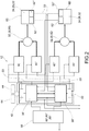
- reference numeral 4 globally denotes a braking system for vehicles.
- vehicles means motor vehicles equipped with at least four wheels.
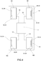
- the braking system for vehicles 4 comprises a right front brake group 8d and a left front brake group 8s intended for the front axle 12 of a vehicle, right rear brake group 16d and a left rear brake group 16s intended for a rear axle 20 of a vehicle.
- Each brake group 8d, 8s, 16d, 16s comprises a brake disc 24, a braking device 28 associated with said brake disc 24, electromechanical actuator means 32 of each braking device 28.
- the braking device 28 may be of various types, preferably comprising a disk brake; however, drum or roller brakes are also included among the applications of the present invention.
- the electromechanical actuator means 32 may comprise electric motors configured in such a way as to enable and disable the braking devices.
- said electromechanical actuator means 32 may comprise an electric motor connected, by means of a worm screw mechanism, to a pusher for at least one piston acting on a pad of a disk brake caliper.
- Each brake group 8d, 8s, 16d, 16s further comprises a control unit 36 operatively connected to the electromechanical actuators 32 of each brake group 8d, 8s, 16d, 16s through a relative piloting device 40.
- Such a connection may for example take place via an electric line.
- the electromechanical actuator means 32 may comprise a three-phase motor 34; each three-phase motor 34 is operatively connected to the respective piloting device 40 and to a power supply device 42 connected to at least two separate power sources 44.
- each power source is galvanically isolated from the other power sources 44.
- the power source 44 is typically a lead battery, a lithium ion battery and the like.
- each control unit 36 is programmed to implement, via said piloting device 40, a standard braking strategy in case of normal operating conditions for each brake group 8d, 8s, 16d, 16s and a fault braking strategy, if it detects an electrical fault of one or more of the brake groups 8d, 8s, 16d, 16s.
- Standard operation means a normal operating condition in which there are no anomalies in the braking system that is able to exert the braking action requested by the user or by the autonomous driving system of the vehicle (if provided).
- Electric fault condition means a malfunction of a brake group 8d, 8s, 16d, 16s, for example of the supply devices 42, of the piloting devices 40, of the power supply sources 44, of the electromechanical actuator means 32,34, 35 that partially or totally prevents the operation thereof.
- 'Fault' means a generic condition of malfunction which may include a problem both to the mechanical components (braking devices 28 and/or electromechanical actuator means 32) and to the electrical/electronic components, but may also comprise a software problem of management of the control unit, reading of the data concerning the operation of the system and the like.
- each piloting device 40 is programmed to switch from a first switch condition, corresponding to the standard braking strategy, to a second switch position corresponding to the fault-braking strategy.
- the standard braking strategy implements the actuation of each brake group 8d, 8s, 16d, 16s according to the standard operating parameters of the system, while the fault strategy can result in a reduced or emergency actuation of a brake group of the system compared to the standard strategy, as better described below.
- control units 36 of all the brake groups 8d, 8s, 16d, 16s are operatively connected to each other so that each knows the type of operation, standard or fault, implemented by each of the other control units 36.
- Such a connection may for example take place via an electric line and/or a data transmission line 33, for example of the CAN type.
- the control units having detected a fault condition, can manage the vehicle braking by implementing the fault strategy.
- each electromechanical means 32 is equipped with at least one operating sensor 52 suitable to monitor the operating condition of the relative electromechanical or actuator means 32 and/or of the relative braking device 28 and to send the corresponding control unit 36 an indication of standard or fault operation. This information is then sent to the other control units 36.
- control units 36 are programmed so that in case of fault of a brake group, the actuation of the remaining brake groups is ensured.
- the two front brake groups 8d, 8s are actuated and, progressively, the remaining rear brake group 16s, 16d so as to allow the dynamic control of the vehicle.
- the overall operation of three brake groups is guaranteed, giving priority to the two front brake groups 8d, 8s which ensure most of the braking action, guaranteeing better stability of the vehicle and allowing, progressively, even the braking of the third rear brake group 16d, 16s so that this does not compromise the stability of the vehicle. Obviously, the remaining faulted brake group remains deactivated.
- the other non-faulted front brake group 8s, 8d is actuated and the corresponding crossover rear brake group 16d, 16s, i.e. arranged on the opposite side to the functioning front brake group 8s, 8d and, progressively, the remaining rear brake group 16s, 16d, on the same side as the functioning front brake group 8s, 8d.
- the initially simultaneous and crossed operation between a front brake group 8d, 8s and a rear brake group 16s, 16d serves to ensure the dynamic stability of the vehicle, especially in yaw, avoiding operating only the braking devices 28 arranged on the same side (right or left) of the vehicle.
- the addition of the third braking device 28 also serves to increase the overall braking action of the system 4, thus limiting the malfunction to a single brake group 8d, 8s, 16d, 16s.
- control units 36 are programmed so that in the event of a fault in a brake group 8d, 8s, 16d, 16s, the operation of the remaining three brake groups is guaranteed, wherein the braking system is operatively connected to electrical power generation means operatively connected to the brake groups 8d, 8s, 16d, 16s so as to obtain an additional braking action of the vehicle. Furthermore, due to regenerative braking, it is possible to obtain a further braking effect which can compensate for malfunctions of the wheel groups.
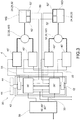
- each control unit 36', 36" of a brake group 8d, 8s, 16d, 16s of a front or rear axle 12, 20 is operatively connected both to a primary piloting device 40' and to a secondary piloting device 40" connected to the other brake group 8s, 8d, 16s, 16d of the same axle 12, 20.
- Such a connection may for example take place via an electric line and/or a data transmission line 33.
- each braking device 28 is actuated by its primary piloting device 40' whereas, in the event of an electrical fault of a brake group 8d, 8s, 16d, 16s in fault, the braking device 28 of the braking device 8d, 8s, 16d, 16s in fault is actuated by the secondary piloting device 40'' controlled by the other control unit 36", 36' of the same axle 12, 20.
- each control unit 36', 36" of a brake group 8d, 8s, 16d, 16s of a front or rear axle 12, 20 is operatively connected both to a primary piloting device 40'and to a secondary piloting device 40", wherein each of said primary and secondary piloting devices 40', 40') is operatively connected to the brake groups 8d, 8s, 16d, 16s of the same axle 12, 20.
- each braking device 28 is actuated by at least one or both of said primary and secondary piloting devices 40', 40" and, in case of electric fault of one of said devices, the braking device 28 of the brake group 8d, 8s, 16d, 16s in fault is actuated by the other functioning piloting device 40", 40'.
- all the control units 36 of the two front and rear axle 12, 20 are operatively connected to each other so that each knows the type of operation, standard or fault, implemented by each of the other control units.
- Such a connection may for example take place via an electric line and/or a data transmission line 33, for example of the CAN type.
- Each electromechanical actuator means 32 is provided with at least one operating sensor and preferably two operating sensors 52', 52", each suitable to monitor the operating condition of the relative electromechanical actuator 32 and/or of the relative braking device 28 and to send an indication of standard or fault operation to both the control units of the same axle 12, 20.
- the electromechanical actuator means 32 comprise a six-phase motor 35.
- Each six-phase motor 35 is operatively connected to the primary piloting device 40' of its own brake group 8d, 8s, 16d, 16s and to the secondary piloting device 40" of the other brake group 8s, 8d, 16s, 16d of the same axle 12, 20.
- Such a connection may for example take place via an electric line and/or a data transmission line 33.
- the braking system can always count on the simultaneous braking of all the brake groups 8d, 8s, 16d, 16s even in case of electrical fault of one of them.
- the braking systems 4 of the present invention may be equipped with a manually operated device 56, a lever, foot pedal and/or push button, equipped with at least a relative actuation sensor 60 so as to be able to send each control unit 36 a braking request from a user.
- 3 driving sensors 60', 60", 60'" connected to the same manually operated device 56.
- the signal is picked up and sent when the reading of at least two of the three sensors coincides.
- the braking system 4 is managed by a control unit of the vehicle which manages vehicle dynamics and is able to perform guidance and an independent braking action of the same.
- the braking system for vehicles according to the invention overcomes the drawbacks of the prior art.
- the braking system allows completely eliminating the part of hydraulic backup and in general of backup that requires the manual intervention of the operator typical of traditional braking systems without losing in reliability or safety, even in case of fault.
- system of the present invention lends itself well to being integrated into a self-driving full-electric vehicle, in which the braking action can be controlled autonomously by a control unit which is responsible for driving and controlling the vehicle.
- system of the present invention also lends itself well to non-autonomous driving solutions in which the user manually requests the braking action.
- the braking system guarantees the safety of the braking even in the event of an electrical fault.
- a vehicle check is carried out, for example to correct yawing phenomena
- an additional braking action is obtained to reduce the speed thereof.
- the two actions may be combined with each other.
- all four vehicle wheels may brake, always ensuring the effectiveness of braking and the stability of the vehicle that is not affected.
- the system of the present invention has the same level of reliability and safety of a traditional hydraulic braking system, without the drawbacks of hydraulic backups and without the need for manual backup by an operator, with the advantage that it can also be used on a self-driving vehicle.
Landscapes
- Engineering & Computer Science (AREA)
- Transportation (AREA)
- Mechanical Engineering (AREA)
- Physics & Mathematics (AREA)
- Chemical & Material Sciences (AREA)
- Combustion & Propulsion (AREA)
- Electromagnetism (AREA)
- Fluid Mechanics (AREA)
- Valves And Accessory Devices For Braking Systems (AREA)
- Regulating Braking Force (AREA)
Claims (16)
- Bremssystem für Fahrzeuge (4), umfassend:- eine rechte vordere Bremsgruppe (8d) und eine linke vordere Bremsgruppe (8s), welche für die vordere Achse (12) eines Fahrzeugs vorgesehen sind, sowie eine rechte hintere Bremsgruppe (16d) und eine linke hintere Bremsgruppe (16s), welche für eine hintere Achse (20) eines Fahrzeugs vorgesehen sind;
wobei jede Bremsgruppe (8d, 8s, 16d, 16s) eine Bremsscheibe (24), eine Bremsvorrichtung (28), welche mit der Bremsscheibe (24) assoziiert ist, und elektrohydraulische oder elektromechanische Betätigungsmittel (32) jeder Bremsvorrichtung (28) umfasst,- eine Steuereinheit (36) für jede Bremsgruppe (8d, 8s, 16d, 16s), welche durch eine jeweilige Führungsvorrichtung (40) betriebsbereit mit den elektromechanischen Betätigungseinrichtungen (32) jeder Bremsgruppe (8d, 8s, 16d, 16s) verbunden sind, dadurch gekennzeichnet, dass- jede Steuereinheit (36) durch eine unabhängige Energiequelle (44) angetrieben wird und von den anderen Energiequellen (44) galvanisch getrennt ist,- jede Steuereinheit (36) dazu programmiert ist, mittels der Führungsvorrichtung (40), eine Standardbremsstrategie bei normalen Betriebsbedingungen für jede Bremsgruppe (8d, 8s, 16d, 16s) und eine Störungsbremsstrategie zu implementieren, wenn sie eine elektrische Störung einer oder mehrerer der Bremsgruppen (8d, 8s, 16d, 16s) detektiert. - Bremssystem für Fahrzeuge (4) nach Anspruch 1, wobei jede Steuervorrichtung (40) dazu programmiert ist, von einer ersten Schaltstellung, welche der Standardbremsstrategie entspricht, zu einer zweiten Schaltstellung zu schalten, welche der Störungsbremsstrategie entspricht.
- Bremssystem für Fahrzeuge (4) nach einem der vorhergehenden Ansprüche, wobei alle Steuereinheiten (36) betriebsbereit miteinander verbunden sind, so dass jede die Art des Betriebs kennt, Standard oder Störung, welche von jeder der anderen Steuereinheiten (36) implementiert wird.
- Bremssystem für Fahrzeuge (4) nach einem der vorhergehenden Ansprüche, wobei jede elektromechanische Betätigungseinrichtung (32) mit einem Betriebssensor (52) ausgestattet ist, welcher dazu geeignet ist, die Betriebsbedingungen der jeweiligen elektromechanischen oder elektrohydraulischen Betätigungseinrichtung (32) und/oder der jeweiligen Bremsvorrichtung (28) zu überwachen und der entsprechenden Steuereinheit (36) einen Hinweis auf Standard- oder Störungsbetrieb zu senden.
- Bremssystem für Fahrzeuge (4) nach einem der vorhergehenden Ansprüche, wobei die elektromechanischen Betätigungseinrichtungen (32) einen Dreiphasenmotor umfassen, wobei jeder Dreiphasenmotor (34) betriebsbereit mit der jeweiligen Führungsvorrichtung (40) und der jeweiligen Energiequelle (44) der entsprechenden Bremsgruppe (8d, 8s, 16d, 16s) verbunden ist.
- Bremssystem für Fahrzeuge (4) nach einem der vorhergehenden Ansprüche, wobei die Steuereinheiten (36) derart programmiert sind, dass bei einer Störung einer Bremsgruppe (8d, 8s, 16d, 16s) die Betätigung der verbleibenden Bremsgruppen gewährleistet ist, so dass:wenn die Störung eine hintere Bremsgruppe (16d, 16s) betrifft, die zwei vorderen Bremsgruppen (8d, 8s) betätigt werden und die verbleibende hintere Bremsgruppe (16s, 16d) stufenweise betätigt wird, um die dynamische Steuerung des Fahrzeugs zu ermöglichen,wenn die Störung eine vordere Bremsgruppe (8d, 8s) betrifft, die andere vordere Bremsgruppe (8s, 8d) betätigt wird und die entsprechende hintere überkreuzliegende Bremsgruppe (16d, 16s), d.h. an der gegenüberliegenden Seite zu der arbeitsfähigen vorderen Bremsgruppe (8s, 8d) angeordnet, betätigt wird und die verbleibende hintere Bremsgruppe (16s, 16d) stufenweise betätigt wird, welche sich auf der gleichen Seite wie die arbeitsfähige vordere Bremsgruppe (8s, 8d) befindet.
- Bremssystem für Fahrzeuge (4) nach einem der Ansprüche 1 bis 6, wobei die Steuereinheiten (36) derart programmiert sind, dass bei einer Störung einer Bremsgruppe (8d, 8s, 16d, 16s) die Betätigung der drei verbleibenden Bremsgruppen gewährleistet ist, wobei das Bremssystem betriebsbereit mit einem Lenkmechanismus des Fahrzeugs verbunden ist, um den Betrieb des Lenkmechanismus mit der Betätigung der arbeitsfähigen Bremsgruppen zu koordinieren.
- Bremssystem für Fahrzeuge (4) nach einem der Ansprüche 1 bis 7, wobei die Steuereinheiten (36) derart programmiert sind, dass bei einer Störung einer Bremsgruppe (8d, 8s, 16d, 16s) die Betätigung der drei verbleibenden Bremsgruppen gewährleistet ist, wobei das Bremssystem betriebsbereit mit elektrischen Energieerzeugungsmitteln verbunden ist, welche betriebsbereit mit den Bremsgruppen (8d, 8s, 16d, 16s) verbunden sind, um eine zusätzliche Bremswirkung des Fahrzeugs zu erhalten.
- Bremssystem für Fahrzeuge (4) nach Anspruch 1, wobei jede Steuereinheit (36', 36") einer Bremsgruppe (8d, 8s, 16d, 16s) einer vorderen oder einer hinteren Achse (12, 20) betriebsbereit mit sowohl einer primären Führungsvorrichtung (40'), welche mit der Bremsgruppe davon (8d, 8s, 16d, 16s) verbunden ist, als auch mit einer sekundären Führungsvorrichtung (40") verbunden ist, welche mit der anderen Bremsgruppe (8d, 8s, 16d, 16s) der gleichen Achse (12, 20) verbunden ist, so dass bei einem Standardbetrieb jede Bremsvorrichtung (28) durch deren eigene primäre Steuervorrichtung (40') betätigt wird und bei einer elektrischen Störung einer Bremsgruppe (8d, 8s, 16d, 16s) die Bremsvorrichtung (28) der Bremsgruppe (8d, 8s, 16d, 16s) in Störung durch die sekundäre Steuervorrichtung (40") betätigt wird, welche durch die andere Steuereinheit (36", 36') der gleichen Achse (12, 20) gesteuert wird.
- Bremssystem für Fahrzeuge (4) nach Anspruch 1, wobei jede Steuereinheit (36', 36") einer Bremsgruppe (8d, 8s, 16d, 16s) einer vorderen oder einer hinteren Achse (12, 20) betriebsbereit mit sowohl einer primären Führungsvorrichtung (40') als auch mit einer sekundären Führungsvorrichtung (40") verbunden ist, wobei jede der primären und der sekundären Führungsvorrichtung (40', 40") betriebsbereit mit den Bremsgruppen (8d, 8s, 16d, 16s) der gleichen Achse (12, 20) verbunden ist, so dass bei einem Standardbetrieb jede Bremsvorrichtung (28) durch wenigstens eine oder beide der primären und der sekundären Führungsvorrichtung (40', 40") betätigt wird und bei einer elektrischen Störung einer der Vorrichtungen die Bremsvorrichtung (28) der Bremsgruppe (8d, 8s, 16d, 16s) in Störung durch die andere Führungsvorrichtung (40", 40') betätigt wird.
- Bremssystem für Fahrzeuge (4) nach Anspruch 9 oder 10, wobei die Achse die vordere Achse (12) oder die hintere Achse (20) des Fahrzeugs ist.
- Bremssystem für Fahrzeuge (4) nach Anspruch 9, 10 oder 11, wobei alle Steuereinheiten (36) betriebsbereit miteinander verbunden sind, so dass jede die Art des Betriebs kennt, Standard oder Störung, welche von jeder der anderen Steuereinheiten (36) implementiert wird.
- Bremssystem für Fahrzeuge (4) nach einem der Ansprüche 9 bis 12, wobei jede elektromechanische Betätigungseinrichtung (32) mit zwei Betriebssensoren (52', 52") ausgestattet ist, welche jeweils dazu geeignet sind, die Betriebsbedingungen der jeweiligen elektromechanischen Betätigungseinrichtung (32) und/oder der jeweiligen Bremsvorrichtung (28) zu überwachen und einen Hinweis auf Standard- oder Störungsbetrieb an beide Steuereinheiten (36) zu senden.
- Bremssystem für Fahrzeuge (4) nach einem der Ansprüche 9 bis 13, wobei die elektromechanischen Betätigungseinrichtungen (32) einen Sechsphasenmotor (35) umfassen, wobei jeder Sechsphasenmotor (35) betriebsbereit mit der primären Führungsvorrichtung (40') seiner eigenen Bremsgruppe (8d, 8s, 16d, 16s) und der sekundären Steuereinheit (40") der anderen Bremsgruppe (8d, 8s, 16d, 16s) verbunden ist.
- Bremssystem für Fahrzeuge (4) nach einem der vorhergehenden Ansprüche, wobei das System (4) mit einer handbetriebenen Vorrichtung (56), einem Hebel, einem Fußpedal und/oder einem Druckknopf ausgestattet ist, welche mit einem jeweiligen Betätigungssensor (60) ausgestattet sind, um dazu in der Lage zu sein, jeder Steuereinheit (36) eine Bremsanfrage von einem Benutzer zu senden.
- Bremssystem für Fahrzeuge (4) nach einem der vorhergehenden Ansprüche, wobei das System (4) durch eine Steuereinheit (36) des Fahrzeuges verwaltet wird, welche Fahrzeugdynamiken verwaltet und dazu in der Lage ist, eine Leitung und eine unabhängige Bremswirkung desselben auszuführen.
Applications Claiming Priority (2)
| Application Number | Priority Date | Filing Date | Title |
|---|---|---|---|
| IT102017000105896A IT201700105896A1 (it) | 2017-09-21 | 2017-09-21 | Impianto frenante per veicoli di tipo brake by wire munito di azionamento elettrico e di back-up elettrico |
| PCT/IB2018/056863 WO2019058204A1 (en) | 2017-09-21 | 2018-09-10 | ELECTRIC WIRE BRAKING SYSTEM FOR VEHICLES HAVING ELECTRICAL ACTUATION AND ELECTRICAL SAFETY |
Publications (2)
| Publication Number | Publication Date |
|---|---|
| EP3684661A1 EP3684661A1 (de) | 2020-07-29 |
| EP3684661B1 true EP3684661B1 (de) | 2021-09-22 |
Family
ID=61006210
Family Applications (1)
| Application Number | Title | Priority Date | Filing Date |
|---|---|---|---|
| EP18783571.5A Active EP3684661B1 (de) | 2017-09-21 | 2018-09-10 | Elektromechanisches bremsssystem für fahrzeuge, ausgestattet mit elektrischer betätigung und elektrischer rückfallebene |
Country Status (6)
| Country | Link |
|---|---|
| US (1) | US20200254988A1 (de) |
| EP (1) | EP3684661B1 (de) |
| JP (1) | JP7230009B2 (de) |
| CN (1) | CN111263714B (de) |
| IT (1) | IT201700105896A1 (de) |
| WO (1) | WO2019058204A1 (de) |
Families Citing this family (7)
| Publication number | Priority date | Publication date | Assignee | Title |
|---|---|---|---|---|
| IT201900005254A1 (it) * | 2019-04-05 | 2020-10-05 | Freni Brembo Spa | Impianto frenante per veicoli di tipo brake by wire munito di azionamento elettrico e di back-up elettrico |
| DE102020103660A1 (de) * | 2020-02-12 | 2021-08-12 | Ipgate Ag | Fahrdynamiksystem, E-Fahrzeug mit zentraler Steuerung (M-ECU) |
| IT202000027071A1 (it) * | 2020-11-12 | 2022-05-12 | Brembo Spa | Assieme frenante di stazionamento |
| KR20220108250A (ko) * | 2021-01-25 | 2022-08-03 | 현대자동차주식회사 | 환경차의 고장 제어 시스템 |
| DE102021108523A1 (de) * | 2021-04-06 | 2022-10-06 | Audi Aktiengesellschaft | Bremssystem für ein autonomes Fahrzeug |
| EP4209399A1 (de) * | 2022-01-05 | 2023-07-12 | Volvo Car Corporation | Bremssteuerungssystem zur steuerung eines bremssystems, fahrzeug und verfahren zum betrieb eines bremssteuerungssystems |
| JP2024064114A (ja) * | 2022-10-27 | 2024-05-14 | 株式会社アドヴィックス | ブレーキシステム |
Family Cites Families (23)
| Publication number | Priority date | Publication date | Assignee | Title |
|---|---|---|---|---|
| JPS60169358A (ja) * | 1984-02-13 | 1985-09-02 | Nissan Motor Co Ltd | アンチスキツド制御装置 |
| US20020167218A1 (en) * | 2001-05-09 | 2002-11-14 | Chubb Erik Christopher | Use of steering control to produce deceleration in a vehicle while remaining on a straight ground path |
| JP2004236424A (ja) * | 2003-01-30 | 2004-08-19 | Toyota Motor Corp | 動力出力装置、モータ駆動方法およびモータの駆動制御をコンピュータに実行させるためのプログラムを記録したコンピュータ読取り可能な記録媒体 |
| US6923510B2 (en) * | 2003-09-17 | 2005-08-02 | Delphi Technologies, Inc. | Control of brake-and steer-by-wire systems during brake failure |
| US7437231B2 (en) * | 2005-02-14 | 2008-10-14 | Honeywell International Inc. | Brake system providing at least one enable signal to brake controllers and method of using same |
| DE602006010123D1 (de) * | 2005-02-28 | 2009-12-17 | Delphi Tech Inc | Bremssystem mit einer fehlertoleranten Kommunikationsknoten-Architektur |
| JP4754390B2 (ja) * | 2006-04-03 | 2011-08-24 | 日立オートモティブシステムズ株式会社 | 電動ブレーキ装置 |
| DE102007029632A1 (de) * | 2006-06-27 | 2008-01-10 | Continental Teves Ag & Co. Ohg | Feststellbremsanlage für Kraftfahrzeuge |
| US7739014B2 (en) * | 2006-08-30 | 2010-06-15 | Ford Global Technolgies | Integrated control system for stability control of yaw, roll and lateral motion of a driving vehicle using an integrated sensing system to determine a final linear lateral velocity |
| US7837278B2 (en) * | 2007-05-30 | 2010-11-23 | Haldex Brake Products Ab | Redundant brake actuators for fail safe brake system |
| DE102007036261A1 (de) * | 2007-08-02 | 2009-02-19 | Robert Bosch Gmbh | Bremssystem für ein Fahrzeug und Verfahren zum Betreiben eines Bremssystems für ein Fahrzeug |
| DE102007036259A1 (de) * | 2007-08-02 | 2009-02-05 | Robert Bosch Gmbh | Bremssystem für ein Fahrzeug und ein Verfahren zum Betreiben eines Bremssystems für ein Fahrzeug |
| DE102009041449A1 (de) * | 2008-09-27 | 2010-04-01 | Continental Teves Ag & Co. Ohg | Kombinierte Fahrzeugbremsanlage mit hydraulisch und elektromechanisch betätigbaren Radbremsen |
| US8682559B2 (en) * | 2010-12-14 | 2014-03-25 | Nxp B.V. | Distributed electrical brake circuit and system |
| JP5944718B2 (ja) | 2012-04-04 | 2016-07-05 | Ntn株式会社 | 電動ブレーキ装置 |
| CN103448559B (zh) * | 2013-08-20 | 2016-04-27 | 联合汽车电子有限公司 | 纯电动汽车用电机制动控制系统 |
| DE102014013756C5 (de) * | 2014-09-22 | 2018-04-26 | Knorr-Bremse Systeme für Nutzfahrzeuge GmbH | Elektrische Ausrüstung eines Fahrzeugs mit einer wenigstens teilweise elektrischen Brems- und Lenkeinrichtung mit hoher Verfügbarkeit |
| JP6589416B2 (ja) | 2015-07-02 | 2019-10-16 | 三菱自動車工業株式会社 | 電動ブレーキ装置 |
| JP6575175B2 (ja) * | 2015-07-02 | 2019-09-18 | 三菱自動車工業株式会社 | 電動ブレーキ装置 |
| DE102016213169A1 (de) * | 2015-07-30 | 2017-02-02 | Ford Global Technologies, Llc | Verfahren zur Steuerung einer elektrischen Feststellbremse sowie Steuervorrichtung |
| ITUB20152710A1 (it) * | 2015-07-31 | 2017-01-31 | Freni Brembo Spa | Impianto frenante per veicoli, in particolare cicli e motocicli, e metodo di attuazione di un impianto frenante per veicoli |
| US10525957B2 (en) * | 2016-08-31 | 2020-01-07 | GM Global Technology Operations LLC | Brake-by-wire system |
| DE102017002716A1 (de) * | 2017-03-21 | 2018-09-27 | Wabco Gmbh | Elektronisch steuerbares Bremssystem sowie Verfahren zum Steuern des elektronisch steuerbaren Bremssystems |
-
2017
- 2017-09-21 IT IT102017000105896A patent/IT201700105896A1/it unknown
-
2018
- 2018-09-10 WO PCT/IB2018/056863 patent/WO2019058204A1/en unknown
- 2018-09-10 CN CN201880061304.5A patent/CN111263714B/zh active Active
- 2018-09-10 JP JP2020516426A patent/JP7230009B2/ja active Active
- 2018-09-10 EP EP18783571.5A patent/EP3684661B1/de active Active
- 2018-09-10 US US16/647,725 patent/US20200254988A1/en active Pending
Also Published As
| Publication number | Publication date |
|---|---|
| EP3684661A1 (de) | 2020-07-29 |
| CN111263714A (zh) | 2020-06-09 |
| JP2020534206A (ja) | 2020-11-26 |
| IT201700105896A1 (it) | 2019-03-21 |
| US20200254988A1 (en) | 2020-08-13 |
| WO2019058204A1 (en) | 2019-03-28 |
| JP7230009B2 (ja) | 2023-02-28 |
| CN111263714B (zh) | 2023-06-30 |
Similar Documents
| Publication | Publication Date | Title |
|---|---|---|
| EP3684661B1 (de) | Elektromechanisches bremsssystem für fahrzeuge, ausgestattet mit elektrischer betätigung und elektrischer rückfallebene | |
| US11312343B2 (en) | Motor vehicle control unit for an electric parking brake | |
| US11124169B2 (en) | System comprising separate control units for the actuation units of an electric parking brake | |
| US11046289B2 (en) | System comprising separate control units for the actuation units of an electric parking brake | |
| CN113557184B (zh) | 具有两个后备等级的能电子控制的制动系统 | |
| CN101687498B (zh) | 特别是用于机动车的混合制动系统 | |
| US6015193A (en) | Braking and steering system for a vehicle | |
| CN112703143B (zh) | 用于控制电动车辆的系统和方法 | |
| CN111727143B (zh) | 用于车辆的线控制动的制动系统 | |
| US20030006726A1 (en) | Electrical brake system | |
| US20220340114A1 (en) | Braking system for a vehicle | |
| US10604128B2 (en) | Electronically slip-controllable braking system | |
| US20220396276A1 (en) | Device for controlling an automated driving operation of a vehicle | |
| US20220340118A1 (en) | Braking system for a vehicle | |
| US20220161772A1 (en) | Brake-by-wire braking system for vehicles, provided with electric actuation and electric back-up | |
| CN115195685A (zh) | 用于自主车辆的制动系统 | |
| WO2019003537A1 (ja) | 車両用ブレーキシステム | |
| KR20220124795A (ko) | 전자식 주차 브레이크 시스템의 제어장치 | |
| JPWO2018181808A1 (ja) | 車両用ブレーキシステム | |
| JP5028461B2 (ja) | ブレーキ制御システム | |
| US20240278760A1 (en) | Braking system for a vehicle and method for braking a vehicle | |
| KR20240090715A (ko) | 차량 제어 장치, 차량 제어 방법 및 차량 제어 시스템 | |
| CN118510690A (zh) | 用于机动车辆的制动系统以及液压电子制动系统 |
Legal Events
| Date | Code | Title | Description |
|---|---|---|---|
| STAA | Information on the status of an ep patent application or granted ep patent |
Free format text: STATUS: UNKNOWN |
|
| STAA | Information on the status of an ep patent application or granted ep patent |
Free format text: STATUS: THE INTERNATIONAL PUBLICATION HAS BEEN MADE |
|
| PUAI | Public reference made under article 153(3) epc to a published international application that has entered the european phase |
Free format text: ORIGINAL CODE: 0009012 |
|
| STAA | Information on the status of an ep patent application or granted ep patent |
Free format text: STATUS: REQUEST FOR EXAMINATION WAS MADE |
|
| 17P | Request for examination filed |
Effective date: 20200312 |
|
| AK | Designated contracting states |
Kind code of ref document: A1 Designated state(s): AL AT BE BG CH CY CZ DE DK EE ES FI FR GB GR HR HU IE IS IT LI LT LU LV MC MK MT NL NO PL PT RO RS SE SI SK SM TR |
|
| AX | Request for extension of the european patent |
Extension state: BA ME |
|
| DAV | Request for validation of the european patent (deleted) | ||
| DAX | Request for extension of the european patent (deleted) | ||
| GRAP | Despatch of communication of intention to grant a patent |
Free format text: ORIGINAL CODE: EPIDOSNIGR1 |
|
| STAA | Information on the status of an ep patent application or granted ep patent |
Free format text: STATUS: GRANT OF PATENT IS INTENDED |
|
| INTG | Intention to grant announced |
Effective date: 20210428 |
|
| RIN1 | Information on inventor provided before grant (corrected) |
Inventor name: CAPPELLETTI, LUCA Inventor name: MAZZOLENI, SAMUELE Inventor name: DI STEFANO, MASSIMO |
|
| RAP3 | Party data changed (applicant data changed or rights of an application transferred) |
Owner name: BREMBO S.P.A. |
|
| GRAS | Grant fee paid |
Free format text: ORIGINAL CODE: EPIDOSNIGR3 |
|
| GRAA | (expected) grant |
Free format text: ORIGINAL CODE: 0009210 |
|
| STAA | Information on the status of an ep patent application or granted ep patent |
Free format text: STATUS: THE PATENT HAS BEEN GRANTED |
|
| RAP3 | Party data changed (applicant data changed or rights of an application transferred) |
Owner name: BREMBO S.P.A. |
|
| RIN1 | Information on inventor provided before grant (corrected) |
Inventor name: CAPPELLETTI, LUCA Inventor name: MAZZOLENI, SAMUELE Inventor name: DI STEFANO, MASSIMO |
|
| AK | Designated contracting states |
Kind code of ref document: B1 Designated state(s): AL AT BE BG CH CY CZ DE DK EE ES FI FR GB GR HR HU IE IS IT LI LT LU LV MC MK MT NL NO PL PT RO RS SE SI SK SM TR |
|
| REG | Reference to a national code |
Ref country code: GB Ref legal event code: FG4D |
|
| REG | Reference to a national code |
Ref country code: IE Ref legal event code: FG4D |
|
| REG | Reference to a national code |
Ref country code: DE Ref legal event code: R096 Ref document number: 602018024015 Country of ref document: DE |
|
| REG | Reference to a national code |
Ref country code: CH Ref legal event code: EP Ref country code: AT Ref legal event code: REF Ref document number: 1432101 Country of ref document: AT Kind code of ref document: T Effective date: 20211015 |
|
| REG | Reference to a national code |
Ref country code: LT Ref legal event code: MG9D |
|
| REG | Reference to a national code |
Ref country code: NL Ref legal event code: MP Effective date: 20210922 |
|
| PG25 | Lapsed in a contracting state [announced via postgrant information from national office to epo] |
Ref country code: HR Free format text: LAPSE BECAUSE OF FAILURE TO SUBMIT A TRANSLATION OF THE DESCRIPTION OR TO PAY THE FEE WITHIN THE PRESCRIBED TIME-LIMIT Effective date: 20210922 Ref country code: FI Free format text: LAPSE BECAUSE OF FAILURE TO SUBMIT A TRANSLATION OF THE DESCRIPTION OR TO PAY THE FEE WITHIN THE PRESCRIBED TIME-LIMIT Effective date: 20210922 Ref country code: SE Free format text: LAPSE BECAUSE OF FAILURE TO SUBMIT A TRANSLATION OF THE DESCRIPTION OR TO PAY THE FEE WITHIN THE PRESCRIBED TIME-LIMIT Effective date: 20210922 Ref country code: RS Free format text: LAPSE BECAUSE OF FAILURE TO SUBMIT A TRANSLATION OF THE DESCRIPTION OR TO PAY THE FEE WITHIN THE PRESCRIBED TIME-LIMIT Effective date: 20210922 Ref country code: LT Free format text: LAPSE BECAUSE OF FAILURE TO SUBMIT A TRANSLATION OF THE DESCRIPTION OR TO PAY THE FEE WITHIN THE PRESCRIBED TIME-LIMIT Effective date: 20210922 Ref country code: BG Free format text: LAPSE BECAUSE OF FAILURE TO SUBMIT A TRANSLATION OF THE DESCRIPTION OR TO PAY THE FEE WITHIN THE PRESCRIBED TIME-LIMIT Effective date: 20211222 Ref country code: NO Free format text: LAPSE BECAUSE OF FAILURE TO SUBMIT A TRANSLATION OF THE DESCRIPTION OR TO PAY THE FEE WITHIN THE PRESCRIBED TIME-LIMIT Effective date: 20211222 |
|
| REG | Reference to a national code |
Ref country code: AT Ref legal event code: MK05 Ref document number: 1432101 Country of ref document: AT Kind code of ref document: T Effective date: 20210922 |
|
| PG25 | Lapsed in a contracting state [announced via postgrant information from national office to epo] |
Ref country code: LV Free format text: LAPSE BECAUSE OF FAILURE TO SUBMIT A TRANSLATION OF THE DESCRIPTION OR TO PAY THE FEE WITHIN THE PRESCRIBED TIME-LIMIT Effective date: 20210922 Ref country code: GR Free format text: LAPSE BECAUSE OF FAILURE TO SUBMIT A TRANSLATION OF THE DESCRIPTION OR TO PAY THE FEE WITHIN THE PRESCRIBED TIME-LIMIT Effective date: 20211223 |
|
| PG25 | Lapsed in a contracting state [announced via postgrant information from national office to epo] |
Ref country code: AT Free format text: LAPSE BECAUSE OF FAILURE TO SUBMIT A TRANSLATION OF THE DESCRIPTION OR TO PAY THE FEE WITHIN THE PRESCRIBED TIME-LIMIT Effective date: 20210922 |
|
| PG25 | Lapsed in a contracting state [announced via postgrant information from national office to epo] |
Ref country code: IS Free format text: LAPSE BECAUSE OF FAILURE TO SUBMIT A TRANSLATION OF THE DESCRIPTION OR TO PAY THE FEE WITHIN THE PRESCRIBED TIME-LIMIT Effective date: 20220122 Ref country code: SK Free format text: LAPSE BECAUSE OF FAILURE TO SUBMIT A TRANSLATION OF THE DESCRIPTION OR TO PAY THE FEE WITHIN THE PRESCRIBED TIME-LIMIT Effective date: 20210922 Ref country code: RO Free format text: LAPSE BECAUSE OF FAILURE TO SUBMIT A TRANSLATION OF THE DESCRIPTION OR TO PAY THE FEE WITHIN THE PRESCRIBED TIME-LIMIT Effective date: 20210922 Ref country code: PT Free format text: LAPSE BECAUSE OF FAILURE TO SUBMIT A TRANSLATION OF THE DESCRIPTION OR TO PAY THE FEE WITHIN THE PRESCRIBED TIME-LIMIT Effective date: 20220124 Ref country code: PL Free format text: LAPSE BECAUSE OF FAILURE TO SUBMIT A TRANSLATION OF THE DESCRIPTION OR TO PAY THE FEE WITHIN THE PRESCRIBED TIME-LIMIT Effective date: 20210922 Ref country code: NL Free format text: LAPSE BECAUSE OF FAILURE TO SUBMIT A TRANSLATION OF THE DESCRIPTION OR TO PAY THE FEE WITHIN THE PRESCRIBED TIME-LIMIT Effective date: 20210922 Ref country code: ES Free format text: LAPSE BECAUSE OF FAILURE TO SUBMIT A TRANSLATION OF THE DESCRIPTION OR TO PAY THE FEE WITHIN THE PRESCRIBED TIME-LIMIT Effective date: 20210922 Ref country code: EE Free format text: LAPSE BECAUSE OF FAILURE TO SUBMIT A TRANSLATION OF THE DESCRIPTION OR TO PAY THE FEE WITHIN THE PRESCRIBED TIME-LIMIT Effective date: 20210922 Ref country code: CZ Free format text: LAPSE BECAUSE OF FAILURE TO SUBMIT A TRANSLATION OF THE DESCRIPTION OR TO PAY THE FEE WITHIN THE PRESCRIBED TIME-LIMIT Effective date: 20210922 Ref country code: AL Free format text: LAPSE BECAUSE OF FAILURE TO SUBMIT A TRANSLATION OF THE DESCRIPTION OR TO PAY THE FEE WITHIN THE PRESCRIBED TIME-LIMIT Effective date: 20210922 |
|
| REG | Reference to a national code |
Ref country code: DE Ref legal event code: R097 Ref document number: 602018024015 Country of ref document: DE |
|
| PG25 | Lapsed in a contracting state [announced via postgrant information from national office to epo] |
Ref country code: DK Free format text: LAPSE BECAUSE OF FAILURE TO SUBMIT A TRANSLATION OF THE DESCRIPTION OR TO PAY THE FEE WITHIN THE PRESCRIBED TIME-LIMIT Effective date: 20210922 |
|
| PLBE | No opposition filed within time limit |
Free format text: ORIGINAL CODE: 0009261 |
|
| STAA | Information on the status of an ep patent application or granted ep patent |
Free format text: STATUS: NO OPPOSITION FILED WITHIN TIME LIMIT |
|
| 26N | No opposition filed |
Effective date: 20220623 |
|
| PG25 | Lapsed in a contracting state [announced via postgrant information from national office to epo] |
Ref country code: SI Free format text: LAPSE BECAUSE OF FAILURE TO SUBMIT A TRANSLATION OF THE DESCRIPTION OR TO PAY THE FEE WITHIN THE PRESCRIBED TIME-LIMIT Effective date: 20210922 |
|
| PG25 | Lapsed in a contracting state [announced via postgrant information from national office to epo] |
Ref country code: IT Free format text: LAPSE BECAUSE OF FAILURE TO SUBMIT A TRANSLATION OF THE DESCRIPTION OR TO PAY THE FEE WITHIN THE PRESCRIBED TIME-LIMIT Effective date: 20210922 |
|
| PG25 | Lapsed in a contracting state [announced via postgrant information from national office to epo] |
Ref country code: MC Free format text: LAPSE BECAUSE OF FAILURE TO SUBMIT A TRANSLATION OF THE DESCRIPTION OR TO PAY THE FEE WITHIN THE PRESCRIBED TIME-LIMIT Effective date: 20210922 |
|
| REG | Reference to a national code |
Ref country code: CH Ref legal event code: PL |
|
| REG | Reference to a national code |
Ref country code: BE Ref legal event code: MM Effective date: 20220930 |
|
| PG25 | Lapsed in a contracting state [announced via postgrant information from national office to epo] |
Ref country code: LU Free format text: LAPSE BECAUSE OF NON-PAYMENT OF DUE FEES Effective date: 20220910 |
|
| P01 | Opt-out of the competence of the unified patent court (upc) registered |
Effective date: 20230526 |
|
| PG25 | Lapsed in a contracting state [announced via postgrant information from national office to epo] |
Ref country code: LI Free format text: LAPSE BECAUSE OF NON-PAYMENT OF DUE FEES Effective date: 20220930 Ref country code: IE Free format text: LAPSE BECAUSE OF NON-PAYMENT OF DUE FEES Effective date: 20220910 Ref country code: CH Free format text: LAPSE BECAUSE OF NON-PAYMENT OF DUE FEES Effective date: 20220930 |
|
| PG25 | Lapsed in a contracting state [announced via postgrant information from national office to epo] |
Ref country code: BE Free format text: LAPSE BECAUSE OF NON-PAYMENT OF DUE FEES Effective date: 20220930 |
|
| PGFP | Annual fee paid to national office [announced via postgrant information from national office to epo] |
Ref country code: GB Payment date: 20230920 Year of fee payment: 6 |
|
| PGFP | Annual fee paid to national office [announced via postgrant information from national office to epo] |
Ref country code: FR Payment date: 20230927 Year of fee payment: 6 Ref country code: DE Payment date: 20230920 Year of fee payment: 6 |
|
| PG25 | Lapsed in a contracting state [announced via postgrant information from national office to epo] |
Ref country code: SM Free format text: LAPSE BECAUSE OF FAILURE TO SUBMIT A TRANSLATION OF THE DESCRIPTION OR TO PAY THE FEE WITHIN THE PRESCRIBED TIME-LIMIT Effective date: 20210922 Ref country code: CY Free format text: LAPSE BECAUSE OF FAILURE TO SUBMIT A TRANSLATION OF THE DESCRIPTION OR TO PAY THE FEE WITHIN THE PRESCRIBED TIME-LIMIT Effective date: 20210922 |
|
| PG25 | Lapsed in a contracting state [announced via postgrant information from national office to epo] |
Ref country code: MK Free format text: LAPSE BECAUSE OF FAILURE TO SUBMIT A TRANSLATION OF THE DESCRIPTION OR TO PAY THE FEE WITHIN THE PRESCRIBED TIME-LIMIT Effective date: 20210922 Ref country code: HU Free format text: LAPSE BECAUSE OF FAILURE TO SUBMIT A TRANSLATION OF THE DESCRIPTION OR TO PAY THE FEE WITHIN THE PRESCRIBED TIME-LIMIT; INVALID AB INITIO Effective date: 20180910 |
|
| PG25 | Lapsed in a contracting state [announced via postgrant information from national office to epo] |
Ref country code: TR Free format text: LAPSE BECAUSE OF FAILURE TO SUBMIT A TRANSLATION OF THE DESCRIPTION OR TO PAY THE FEE WITHIN THE PRESCRIBED TIME-LIMIT Effective date: 20210922 |