EP3684640B1 - Dynamisch biegbare fahrzeuginnenraumanzeigesysteme - Google Patents
Dynamisch biegbare fahrzeuginnenraumanzeigesysteme Download PDFInfo
- Publication number
- EP3684640B1 EP3684640B1 EP19832500.3A EP19832500A EP3684640B1 EP 3684640 B1 EP3684640 B1 EP 3684640B1 EP 19832500 A EP19832500 A EP 19832500A EP 3684640 B1 EP3684640 B1 EP 3684640B1
- Authority
- EP
- European Patent Office
- Prior art keywords
- mpa
- frame
- micrometers
- cover substrate
- micrometer
- Prior art date
- Legal status (The legal status is an assumption and is not a legal conclusion. Google has not performed a legal analysis and makes no representation as to the accuracy of the status listed.)
- Active
Links
- 239000000758 substrate Substances 0.000 claims description 153
- 239000011521 glass Substances 0.000 claims description 60
- 230000002441 reversible effect Effects 0.000 claims description 49
- 239000000853 adhesive Substances 0.000 claims description 3
- 230000001070 adhesive effect Effects 0.000 claims description 3
- 239000002241 glass-ceramic Substances 0.000 description 39
- 238000005452 bending Methods 0.000 description 24
- FGIUAXJPYTZDNR-UHFFFAOYSA-N potassium nitrate Chemical compound [K+].[O-][N+]([O-])=O FGIUAXJPYTZDNR-UHFFFAOYSA-N 0.000 description 18
- 239000000203 mixture Substances 0.000 description 16
- VWDWKYIASSYTQR-UHFFFAOYSA-N sodium nitrate Chemical compound [Na+].[O-][N+]([O-])=O VWDWKYIASSYTQR-UHFFFAOYSA-N 0.000 description 14
- 150000002500 ions Chemical class 0.000 description 13
- 239000000463 material Substances 0.000 description 13
- 150000003839 salts Chemical class 0.000 description 11
- 230000003667 anti-reflective effect Effects 0.000 description 9
- 239000010410 layer Substances 0.000 description 9
- 238000007654 immersion Methods 0.000 description 8
- 238000000034 method Methods 0.000 description 8
- 239000006059 cover glass Substances 0.000 description 7
- 235000010333 potassium nitrate Nutrition 0.000 description 7
- 238000005259 measurement Methods 0.000 description 6
- 229920000642 polymer Polymers 0.000 description 6
- 235000010344 sodium nitrate Nutrition 0.000 description 6
- 230000005540 biological transmission Effects 0.000 description 5
- 238000000576 coating method Methods 0.000 description 5
- 238000005342 ion exchange Methods 0.000 description 5
- 210000003127 knee Anatomy 0.000 description 5
- 230000003287 optical effect Effects 0.000 description 5
- 238000004381 surface treatment Methods 0.000 description 5
- -1 alkali metal cations Chemical class 0.000 description 4
- 239000011248 coating agent Substances 0.000 description 4
- 229920001577 copolymer Polymers 0.000 description 4
- 229920001971 elastomer Polymers 0.000 description 4
- 239000003513 alkali Substances 0.000 description 3
- 239000002585 base Substances 0.000 description 3
- 150000001768 cations Chemical class 0.000 description 3
- 230000003670 easy-to-clean Effects 0.000 description 3
- 230000009975 flexible effect Effects 0.000 description 3
- 239000004973 liquid crystal related substance Substances 0.000 description 3
- 239000004033 plastic Substances 0.000 description 3
- 229920003023 plastic Polymers 0.000 description 3
- 238000002834 transmittance Methods 0.000 description 3
- 239000004697 Polyetherimide Substances 0.000 description 2
- 239000005358 alkali aluminosilicate glass Substances 0.000 description 2
- 229910052783 alkali metal Inorganic materials 0.000 description 2
- 230000008901 benefit Effects 0.000 description 2
- 239000005388 borosilicate glass Substances 0.000 description 2
- 230000007423 decrease Effects 0.000 description 2
- 230000032798 delamination Effects 0.000 description 2
- 230000000694 effects Effects 0.000 description 2
- IIPYXGDZVMZOAP-UHFFFAOYSA-N lithium nitrate Chemical compound [Li+].[O-][N+]([O-])=O IIPYXGDZVMZOAP-UHFFFAOYSA-N 0.000 description 2
- 229910052751 metal Inorganic materials 0.000 description 2
- 239000002184 metal Substances 0.000 description 2
- 150000002823 nitrates Chemical class 0.000 description 2
- 229920003229 poly(methyl methacrylate) Polymers 0.000 description 2
- 229920001601 polyetherimide Polymers 0.000 description 2
- 229920000139 polyethylene terephthalate Polymers 0.000 description 2
- 239000005020 polyethylene terephthalate Substances 0.000 description 2
- 239000004926 polymethyl methacrylate Substances 0.000 description 2
- 229920000098 polyolefin Polymers 0.000 description 2
- 210000001747 pupil Anatomy 0.000 description 2
- 229910052594 sapphire Inorganic materials 0.000 description 2
- 239000010980 sapphire Substances 0.000 description 2
- 229910052596 spinel Inorganic materials 0.000 description 2
- 238000005728 strengthening Methods 0.000 description 2
- 239000002344 surface layer Substances 0.000 description 2
- 229920002803 thermoplastic polyurethane Polymers 0.000 description 2
- 239000004593 Epoxy Substances 0.000 description 1
- 229920000877 Melamine resin Polymers 0.000 description 1
- 229910026161 MgAl2O4 Inorganic materials 0.000 description 1
- 239000004988 Nematic liquid crystal Substances 0.000 description 1
- 229920001890 Novodur Polymers 0.000 description 1
- 239000004793 Polystyrene Substances 0.000 description 1
- 229910000831 Steel Inorganic materials 0.000 description 1
- PPBRXRYQALVLMV-UHFFFAOYSA-N Styrene Natural products C=CC1=CC=CC=C1 PPBRXRYQALVLMV-UHFFFAOYSA-N 0.000 description 1
- 229910001413 alkali metal ion Inorganic materials 0.000 description 1
- PNEYBMLMFCGWSK-UHFFFAOYSA-N aluminium oxide Inorganic materials [O-2].[O-2].[O-2].[Al+3].[Al+3] PNEYBMLMFCGWSK-UHFFFAOYSA-N 0.000 description 1
- 239000005407 aluminoborosilicate glass Substances 0.000 description 1
- 238000000137 annealing Methods 0.000 description 1
- 230000003666 anti-fingerprint Effects 0.000 description 1
- 238000000149 argon plasma sintering Methods 0.000 description 1
- 150000001805 chlorine compounds Chemical class 0.000 description 1
- 238000005253 cladding Methods 0.000 description 1
- 230000006835 compression Effects 0.000 description 1
- 238000007906 compression Methods 0.000 description 1
- 239000013078 crystal Substances 0.000 description 1
- 230000003247 decreasing effect Effects 0.000 description 1
- 230000001419 dependent effect Effects 0.000 description 1
- 238000000151 deposition Methods 0.000 description 1
- 238000005530 etching Methods 0.000 description 1
- 230000001747 exhibiting effect Effects 0.000 description 1
- 230000009477 glass transition Effects 0.000 description 1
- 238000010438 heat treatment Methods 0.000 description 1
- 238000005286 illumination Methods 0.000 description 1
- 238000009863 impact test Methods 0.000 description 1
- 229910010272 inorganic material Inorganic materials 0.000 description 1
- 239000011147 inorganic material Substances 0.000 description 1
- JDSHMPZPIAZGSV-UHFFFAOYSA-N melamine Chemical compound NC1=NC(N)=NC(N)=N1 JDSHMPZPIAZGSV-UHFFFAOYSA-N 0.000 description 1
- 230000003647 oxidation Effects 0.000 description 1
- 238000007254 oxidation reaction Methods 0.000 description 1
- 239000003973 paint Substances 0.000 description 1
- ISWSIDIOOBJBQZ-UHFFFAOYSA-N phenol group Chemical group C1(=CC=CC=C1)O ISWSIDIOOBJBQZ-UHFFFAOYSA-N 0.000 description 1
- 229920001568 phenolic resin Polymers 0.000 description 1
- 239000000049 pigment Substances 0.000 description 1
- 229920000058 polyacrylate Polymers 0.000 description 1
- 239000004417 polycarbonate Substances 0.000 description 1
- 229920000515 polycarbonate Polymers 0.000 description 1
- 229920000647 polyepoxide Polymers 0.000 description 1
- 229920000728 polyester Polymers 0.000 description 1
- 239000004800 polyvinyl chloride Substances 0.000 description 1
- 239000010453 quartz Substances 0.000 description 1
- 238000010791 quenching Methods 0.000 description 1
- 230000000171 quenching effect Effects 0.000 description 1
- VYPSYNLAJGMNEJ-UHFFFAOYSA-N silicon dioxide Inorganic materials O=[Si]=O VYPSYNLAJGMNEJ-UHFFFAOYSA-N 0.000 description 1
- 229920002050 silicone resin Polymers 0.000 description 1
- 239000005361 soda-lime glass Substances 0.000 description 1
- 239000011029 spinel Substances 0.000 description 1
- 238000007655 standard test method Methods 0.000 description 1
- 239000010959 steel Substances 0.000 description 1
- 150000003467 sulfuric acid derivatives Chemical class 0.000 description 1
- 230000003746 surface roughness Effects 0.000 description 1
- 238000012360 testing method Methods 0.000 description 1
- 229920001169 thermoplastic Polymers 0.000 description 1
- 239000004416 thermosoftening plastic Substances 0.000 description 1
- 238000005406 washing Methods 0.000 description 1
Images


Classifications
-
- B—PERFORMING OPERATIONS; TRANSPORTING
- B60—VEHICLES IN GENERAL
- B60K—ARRANGEMENT OR MOUNTING OF PROPULSION UNITS OR OF TRANSMISSIONS IN VEHICLES; ARRANGEMENT OR MOUNTING OF PLURAL DIVERSE PRIME-MOVERS IN VEHICLES; AUXILIARY DRIVES FOR VEHICLES; INSTRUMENTATION OR DASHBOARDS FOR VEHICLES; ARRANGEMENTS IN CONNECTION WITH COOLING, AIR INTAKE, GAS EXHAUST OR FUEL SUPPLY OF PROPULSION UNITS IN VEHICLES
- B60K35/00—Arrangement of adaptations of instruments
-
- B60K35/22—
-
- B60K35/223—
-
- B60K35/50—
-
- B60K35/53—
-
- B60K35/60—
-
- C—CHEMISTRY; METALLURGY
- C03—GLASS; MINERAL OR SLAG WOOL
- C03B—MANUFACTURE, SHAPING, OR SUPPLEMENTARY PROCESSES
- C03B23/00—Re-forming shaped glass
- C03B23/02—Re-forming glass sheets
- C03B23/023—Re-forming glass sheets by bending
-
- C—CHEMISTRY; METALLURGY
- C03—GLASS; MINERAL OR SLAG WOOL
- C03C—CHEMICAL COMPOSITION OF GLASSES, GLAZES OR VITREOUS ENAMELS; SURFACE TREATMENT OF GLASS; SURFACE TREATMENT OF FIBRES OR FILAMENTS MADE FROM GLASS, MINERALS OR SLAGS; JOINING GLASS TO GLASS OR OTHER MATERIALS
- C03C15/00—Surface treatment of glass, not in the form of fibres or filaments, by etching
-
- C—CHEMISTRY; METALLURGY
- C03—GLASS; MINERAL OR SLAG WOOL
- C03C—CHEMICAL COMPOSITION OF GLASSES, GLAZES OR VITREOUS ENAMELS; SURFACE TREATMENT OF GLASS; SURFACE TREATMENT OF FIBRES OR FILAMENTS MADE FROM GLASS, MINERALS OR SLAGS; JOINING GLASS TO GLASS OR OTHER MATERIALS
- C03C17/00—Surface treatment of glass, not in the form of fibres or filaments, by coating
- C03C17/34—Surface treatment of glass, not in the form of fibres or filaments, by coating with at least two coatings having different compositions
-
- G—PHYSICS
- G02—OPTICS
- G02F—OPTICAL DEVICES OR ARRANGEMENTS FOR THE CONTROL OF LIGHT BY MODIFICATION OF THE OPTICAL PROPERTIES OF THE MEDIA OF THE ELEMENTS INVOLVED THEREIN; NON-LINEAR OPTICS; FREQUENCY-CHANGING OF LIGHT; OPTICAL LOGIC ELEMENTS; OPTICAL ANALOGUE/DIGITAL CONVERTERS
- G02F1/00—Devices or arrangements for the control of the intensity, colour, phase, polarisation or direction of light arriving from an independent light source, e.g. switching, gating or modulating; Non-linear optics
- G02F1/01—Devices or arrangements for the control of the intensity, colour, phase, polarisation or direction of light arriving from an independent light source, e.g. switching, gating or modulating; Non-linear optics for the control of the intensity, phase, polarisation or colour
- G02F1/13—Devices or arrangements for the control of the intensity, colour, phase, polarisation or direction of light arriving from an independent light source, e.g. switching, gating or modulating; Non-linear optics for the control of the intensity, phase, polarisation or colour based on liquid crystals, e.g. single liquid crystal display cells
- G02F1/133—Constructional arrangements; Operation of liquid crystal cells; Circuit arrangements
- G02F1/1333—Constructional arrangements; Manufacturing methods
- G02F1/133305—Flexible substrates, e.g. plastics, organic film
-
- G—PHYSICS
- G06—COMPUTING; CALCULATING OR COUNTING
- G06F—ELECTRIC DIGITAL DATA PROCESSING
- G06F1/00—Details not covered by groups G06F3/00 - G06F13/00 and G06F21/00
- G06F1/16—Constructional details or arrangements
- G06F1/1613—Constructional details or arrangements for portable computers
- G06F1/1633—Constructional details or arrangements of portable computers not specific to the type of enclosures covered by groups G06F1/1615 - G06F1/1626
- G06F1/1637—Details related to the display arrangement, including those related to the mounting of the display in the housing
- G06F1/1652—Details related to the display arrangement, including those related to the mounting of the display in the housing the display being flexible, e.g. mimicking a sheet of paper, or rollable
-
- H—ELECTRICITY
- H05—ELECTRIC TECHNIQUES NOT OTHERWISE PROVIDED FOR
- H05K—PRINTED CIRCUITS; CASINGS OR CONSTRUCTIONAL DETAILS OF ELECTRIC APPARATUS; MANUFACTURE OF ASSEMBLAGES OF ELECTRICAL COMPONENTS
- H05K5/00—Casings, cabinets or drawers for electric apparatus
- H05K5/0017—Casings, cabinets or drawers for electric apparatus with operator interface units
-
- H—ELECTRICITY
- H05—ELECTRIC TECHNIQUES NOT OTHERWISE PROVIDED FOR
- H05K—PRINTED CIRCUITS; CASINGS OR CONSTRUCTIONAL DETAILS OF ELECTRIC APPARATUS; MANUFACTURE OF ASSEMBLAGES OF ELECTRICAL COMPONENTS
- H05K5/00—Casings, cabinets or drawers for electric apparatus
- H05K5/02—Details
- H05K5/03—Covers
-
- B—PERFORMING OPERATIONS; TRANSPORTING
- B32—LAYERED PRODUCTS
- B32B—LAYERED PRODUCTS, i.e. PRODUCTS BUILT-UP OF STRATA OF FLAT OR NON-FLAT, e.g. CELLULAR OR HONEYCOMB, FORM
- B32B2307/00—Properties of the layers or laminate
- B32B2307/50—Properties of the layers or laminate having particular mechanical properties
- B32B2307/552—Fatigue strength
-
- B—PERFORMING OPERATIONS; TRANSPORTING
- B32—LAYERED PRODUCTS
- B32B—LAYERED PRODUCTS, i.e. PRODUCTS BUILT-UP OF STRATA OF FLAT OR NON-FLAT, e.g. CELLULAR OR HONEYCOMB, FORM
- B32B2307/00—Properties of the layers or laminate
- B32B2307/50—Properties of the layers or laminate having particular mechanical properties
- B32B2307/558—Impact strength, toughness
-
- B—PERFORMING OPERATIONS; TRANSPORTING
- B32—LAYERED PRODUCTS
- B32B—LAYERED PRODUCTS, i.e. PRODUCTS BUILT-UP OF STRATA OF FLAT OR NON-FLAT, e.g. CELLULAR OR HONEYCOMB, FORM
- B32B2307/00—Properties of the layers or laminate
- B32B2307/50—Properties of the layers or laminate having particular mechanical properties
- B32B2307/56—Damping, energy absorption
-
- B—PERFORMING OPERATIONS; TRANSPORTING
- B32—LAYERED PRODUCTS
- B32B—LAYERED PRODUCTS, i.e. PRODUCTS BUILT-UP OF STRATA OF FLAT OR NON-FLAT, e.g. CELLULAR OR HONEYCOMB, FORM
- B32B2457/00—Electrical equipment
- B32B2457/20—Displays, e.g. liquid crystal displays, plasma displays
-
- B—PERFORMING OPERATIONS; TRANSPORTING
- B60—VEHICLES IN GENERAL
- B60Y—INDEXING SCHEME RELATING TO ASPECTS CROSS-CUTTING VEHICLE TECHNOLOGY
- B60Y2400/00—Special features of vehicle units
- B60Y2400/92—Driver displays
Definitions
- the invention relates to dynamically bendable cover substrates and automotive interior display systems, and more particularly to dynamically bendable automotive interior display systems with a reversible support that dynamically bends a cover substrate sequentially at least from a first radius of curvature to a second radius of curvature and to the first radius of curvature.
- Automotive interiors systems can include surfaces that incorporate displays and/or touch panel and a cover substrate disposed over the displays and/or touch panels. There is a desire to change the shape of the surfaces and in particular, to dynamically change the shape of the surface according to a viewer's needs or preferences. Such dynamic movements should still allow the automotive interiors systems to meet rigorous headform impact test (HIT) requirements. In some instances, the cover substrate should not break after being impacted in the HIT. Accordingly, there is a need for dynamically bendable cover substrates and automotive interior display systems that exhibit improved headform impact performance.
- DE 10 2014 016323 A1 relates to a flexible display apparatus and an adjusting apparatus which is designed to move the flexible display apparatus from a stowing position into a usage position, which are included in a display device for a motor vehicle.
- a touch panel may be substituted or used in addition to the display.
- the cover substrate in dynamically bendable display systems is unsupported when the cover substrate is bent.
- the cover substrate is partially adhered to a frame allowing local dynamic bending in the non-adhered area 20, as shown in Figures 2A and 2B .
- Figure 2A is the cover substrate having a first radius of curvature
- Figure 2B shows the cover substrate dynamically bent to have a second radius of curvature.
- the phrase "radius of curvature” refers to the radius of curvature of the first major surface, the second major surface, or both the first and second major surface of the cover substrate (and not a local radius of curvature) adjacent the bend axis.
- the radius of curvature is the minimum radius of curvature in a given configuration. Without adequate support, there is an increase risk of local stress or bending local in the cover substrate during use (or when the cover substrate is dynamically bent), since the structural integrity is provided by the cover substrate alone. The absence of a support at the bend axis leads to low stiffness which compromises resistance during HIT.
- a first aspect of this disclosure pertains to a dynamically bendable display system that includes a reversible support.
- the reversible support is easily bent, offers local support to the cover substrate at a bend axis, and does not damage the cover substrate.
- the dynamically bendable automotive interior display system 100 includes a display 150, a dynamically bendable cover substrate assembly (120, 130 and 140) disposed over the display.
- the display may be replaced with a touch panel or may have touch functionality.
- the system 100 includes an adhesive between the cover substrate assembly and the display.
- the cover substrate assembly of one or more embodiments includes a cover substrate 120 having a first major surface 121, second major surface 122 opposing the first major surface and a minor surface 126 connecting the first major surface and the second major surface, a thickness defined as a distance between the first major surface and the second major surface, a width defined as a first dimension of one of the first or second major surfaces orthogonal to the thickness, a length defined as a second dimension of one of the first or second major surfaces orthogonal to both the thickness and the width, and a bend axis 125 that defines a bend axis.
- thickness (t) refers to the maximum thickness of the cover substrate.
- the cover substrate comprises a plurality of bend axes. The bend axis may extend across the entire width, the entire length or a diagonal of the cover substrate.
- the cover substrate may include an inorganic material and may include an amorphous substrate, a crystalline substrate or a combination thereof.
- the cover substrate may be formed from man-made materials and/or naturally occurring materials (e.g., quartz and polymers).
- the cover substrate may be characterized as organic and may specifically be polymeric.
- suitable polymers include, without limitation: thermoplastics including polystyrene (PS) (including styrene copolymers and blends), polycarbonate (PC) (including copolymers and blends), polyesters (including copolymers and blends, including polyethyleneterephthalate and polyethyleneterephthalate copolymers), polyolefins (PO) and cyclicpolyolefins (cyclic-PO), polyvinylchloride (PVC), acrylic polymers including polymethyl methacrylate (PMMA) (including copolymers and blends), thermoplastic urethanes (TPU), polyetherimide (PEI) and blends of these polymers with each other.
- Other exemplary polymers include epoxy, styrenic, phenolic, melamine, and silicone resins.
- the cover substrate may specifically exclude polymeric, plastic and/or metal substrates.
- the substrate exhibits a refractive index in the range from about 1.45 to about 1.55.
- the cover substrate may exhibit an average strain-to-failure at a surface on one or more opposing major surface that is 0.5% or greater, 0.6% or greater, 0.7% or greater, 0.8% or greater, 0.9% or greater, 1% or greater, 1.1% or greater, 1.2% or greater, 1.3% or greater, 1.4% or greater 1.5% or greater or even 2% or greater, as measured using ball-on-ring testing using at least 5, at least 10, at least 15, or at least 20 samples.
- the cover substrate may exhibit an average strain-to-failure at its surface on one or more opposing major surface of about 1.2%, about 1.4%, about 1.6%, about 1.8%, about 2.2%, about 2.4%, about 2.6%, about 2.8%, or about 3% or greater.
- Suitable cover substrates may exhibit an elastic modulus (or Young's modulus) in the range from about 30 GPa to about 120 GPa.
- the elastic modulus of the substrate may be in the range from about 30 GPa to about 110 GPa, from about 30 GPa to about 100 GPa, from about 30 GPa to about 90 GPa, from about 30 GPa to about 80 GPa, from about 30 GPa to about 70 GPa, from about 40 GPa to about 120 GPa, from about 50 GPa to about 120 GPa, from about 60 GPa to about 120 GPa, from about 70 GPa to about 120 GPa, and all ranges and sub-ranges therebetween.
- the cover substrates may include an amorphous substrate, which may include a glass article.
- the glass article may be strengthened or non-strengthened.
- suitable glass composition families used to form the glass articles include soda lime glass, alkali aluminosilicate glass, alkali containing borosilicate glass and alkali aluminoborosilicate glass.
- the cover substrate may include crystalline substrates such as glass ceramic article (which may be strengthened or non-strengthened) or may include a single crystal structure, such as sapphire.
- the cover substrate includes an amorphous base (e.g., glass) and a crystalline cladding (e.g., sapphire layer, a polycrystalline alumina layer and/or or a spinel (MgAl 2 O 4 ) layer).
- amorphous base e.g., glass
- a crystalline cladding e.g., sapphire layer, a polycrystalline alumina layer and/or or a spinel (MgAl 2 O 4 ) layer.
- the cover substrate may be substantially sheet-like, although other embodiments may utilize a curved or otherwise shaped or sculpted substrate.
- the cover substrate may be substantially optically clear, transparent and free from light scattering.
- the cover substrate may exhibit an average light transmission over the optical wavelength regime of about 85% or greater, about 86% or greater, about 87% or greater, about 88% or greater, about 89% or greater, about 90% or greater, about 91% or greater or about 92% or greater.
- the cover substrate may be opaque or exhibit an average light transmission over the optical wavelength regime of less than about 10%, less than about 9%, less than about 8%, less than about 7%, less than about 6%, less than about 5%, less than about 4%, less than about 3%, less than about 2%, less than about 1%, or less than about 0%.
- these light transmittance values are total transmittance values (taking into account transmittance through both major surfaces of the substrate)
- the substrate 110 may optionally exhibit a color, such as white, black, red, blue, green, yellow, orange etc.
- the cover substrate assembly also includes a reversible support attached to at least a portion the second major surface of the cover substrate.
- the reversible support is capable of dynamically bending or dynamically bends the cover substrate along the bend axis in a cycle from a first radius of curvature to a second radius of curvature and from the second radius of curvature to the first radius of curvature. This sequence is described herein as a cycle.
- the reversible support is capable of dynamically bending or dynamically bends the cover substrate along the bend axis from having a flat shape to a concave shape and back to a flat shape (from the perspective of the first major surface).
- the reversible support is capable of dynamically bending or dynamically bends the cover substrate along the bend axis from having a flat shape to a convex shape and then back to a flat shape (from the perspective of the first major surface). In one or more embodiments, the reversible support is capable of dynamically bending or dynamically bends the cover substrate along the bend axis from having a concave shape to a convex shape and back to a concave shape (from the perspective of the first major surface).
- the reversible support is capable of dynamically bending or dynamically bends the cover substrate along the bend axis from having a convex shape to a concave shape and back to a convex shape (from the perspective of the first major surface).
- the first radius of curvature is greater than the second radius of curvature. In one or more embodiments, the first radius of curvature is 2 times, 3 times, 4 times or 5 times greater than the second radius of curvature. In one or more specific embodiments, the first radius of curvature is in a range from about 2500 mm to infinity (or a radius of curvature in which the cover substrate is in a flat configuration), or from about 10,000 mm to infinity.
- the second radius of curvature is from about 20 mm to about 10,000 mm, from about 20 mm to about 9,000 mm, from about 20 mm to about 8,000 mm, from about 20 mm to about 7,000 mm, from about 20 mm to about 6,000 mm, from about 20 mm to about 5,000 mm, from about 20 mm to about 4,000 mm, from about 20 mm to about 3,000 mm, from about 20 mm to about 2,000 mm, from about 20 mm to about 1,000 mm, from about 20 mm to about 750 mm, from about 20 mm to about 500 mm from about 20 mm to about 250 mm, from about 50 mm to about 10,000 mm, from about 75 mm to about 10,000 mm, from about 100 mm to about 10,000 mm, from about 200 mm to about 10,000 mm, from about 300 mm to about 10,000 mm, from about 400 mm to about 10,000 mm, from about 500 mm to about 10,000 mm, from about 600 mm to about 10,000 mm, from about 600 mm to about
- the cover substrate has a curvature and is then dynamically bent along the bend axis.
- the cover substrate comprises a cold-bent cover substrate.
- cold-bent refers to curving the cover substrate at a cold-bend temperature which is less than the softening point of the glass. Often, the cold-bend temperature is room temperature.
- cold-bendable refers to the capability of a cover substrate to be cold-bent.
- the cold-bent cover substrate may comprise a glass article or glass ceramic article, which may optionally be strengthened.
- a feature of a cold-bent cover substrate is asymmetric surface compressive stress between the first major surface 121 and the second major surface 122.
- the respective compressive stresses in the first major surface 121 and the second major surface 122 of the cover substrate are substantially equal.
- the cover substrate is unstrengthened, the first major surface 121 and the second major surface 122 exhibit no appreciable compressive stress (CS), prior to cold-bending.
- the cover substrate is strengthened (as described herein), the first major surface 121 and the second major surface 122 exhibit substantially equal compressive stress with respect to one another, prior to cold-bending.
- the CS on the surface having a concave shape after cold-bending increases, while the CS on the surface having a convex shape after cold-bending decreases.
- the CS on the concave surface is greater after cold-bending than before cold-bending.
- the cold-bending process increases the CS of the cover substrate being shaped to compensate for tensile stresses imparted during cold-bending.
- the cold-bending process causes the concave surface to experience compressive stresses, while the surface forming a convex shape after cold-bending experiences tensile stresses.
- the tensile stress experienced by the convex surface following cold-bending results in a net decrease in surface compressive stress, such that the compressive stress in convex surface of a strengthened cover substrate following cold-bending is less than the compressive stress on the same surface when the cover substrate is flat.
- the cover substrate may be a hot-formed glass article, which is permanently curved and the first major surface and the second major surface have the same CS.
- the cover substrate has a thickness (t) that is about 1.5 mm or less. In one or embodiments, the cover substrate has a thickness (t) that is greater than about 0.125 mm (e.g., about 0.13 mm or greater, about 0.13 mm or greater, about 0.13 mm or greater, about 0.13 mm or greater, about 0.13 mm or greater, about 0.13 mm or greater, about 0.13 mm or greater, about 0.13 mm or greater, about 0.13 mm or greater, about 0.13 mm or greater, about 0.13 mm or greater, about 0.13 mm or greater, about 0.13 mm or greater, about 0.13 mm or greater, about 0.13 mm or greater, about 0.13 mm or greater, about 0.13 mm or greater, about 0.13 mm or greater, about 0.13 mm or greater, about 0.13 mm or greater, about 0.13 mm or greater, about 0.13 mm or greater, about 0.13 mm or greater, about 0.13 mm or greater, about 0.13 mm or greater, about 0.13
- the thickness of the cover substrate is substantially uniform in that it the bend axis has substantially the same thickness as other portions of the cover substrate.
- the thickness of the cover substrate does not vary by more than ⁇ 10%, 5% or 2% across the total surface area of the first major surface, the second major surface or both the first and second major surfaces.
- the thickness is substantially constant (within ⁇ 1% of the average thickness) across 90%, 95% or 99% of the total surface area of the first major surface, the second major surface or both the first and second major surfaces.
- the cover substrate has a width (W) in a range from about 5 cm to about 250 cm, from about 10 cm to about 250 cm, from about 15 cm to about 250 cm, from about 20 cm to about 250 cm, from about 25 cm to about 250 cm, from about 30 cm to about 250 cm, from about 35 cm to about 250 cm, from about 40 cm to about 250 cm, from about 45 cm to about 250 cm, from about 50 cm to about 250 cm, from about 55 cm to about 250 cm, from about 60 cm to about 250 cm, from about 65 cm to about 250 cm, from about 70 cm to about 250 cm, from about 75 cm to about 250 cm, from about 80 cm to about 250 cm, from about 85 cm to about 250 cm, from about 90 cm to about 250 cm, from about 95 cm to about 250 cm, from about 100 cm to about 250 cm, from about 110 cm to about 250 cm, from about 120 cm to about 250 cm, from about 130 cm to about 250 cm, from about 140 cm to about 250 cm, from about 150 cm to about 250 cm, from about 5 cm to about 240 cm
- the cover substrate has a length (L) in a range from about 5 cm to about 250 cm, from about 10 cm to about 250 cm, from about 15 cm to about 250 cm, from about 20 cm to about 250 cm, from about 25 cm to about 250 cm, from about 30 cm to about 250 cm, from about 35 cm to about 250 cm, from about 40 cm to about 250 cm, from about 45 cm to about 250 cm, from about 50 cm to about 250 cm, from about 55 cm to about 250 cm, from about 60 cm to about 250 cm, from about 65 cm to about 250 cm, from about 70 cm to about 250 cm, from about 75 cm to about 250 cm, from about 80 cm to about 250 cm, from about 85 cm to about 250 cm, from about 90 cm to about 250 cm, from about 95 cm to about 250 cm, from about 100 cm to about 250 cm, from about 110 cm to about 250 cm, from about 120 cm to about 250 cm, from about 130 cm to about 250 cm, from about 140 cm to about 250 cm, from about 150 cm to about 250 cm, from about 5 cm to about 240 cm
- the cover substrate includes a glass article or glass ceramic article that is strengthened.
- the cover glass has a compressive stress (CS) region that extends from one or both major surfaces 121, 122, to a first depth of compression (DOC).
- the CS region includes a maximum CS magnitude (CS- max ).
- the glass article or glass ceramic has a CT region disposed in the central region that extends from the DOC to an opposing CS region.
- the CT region defines a maximum CT magnitude (CTmax).
- CTmax maximum CT magnitude
- the CS region and the CT region define a stress profile that extends along the thickness of the glass article or glass ceramic.
- the glass article or glass ceramic article may be strengthened mechanically by utilizing a mismatch of the coefficient of thermal expansion between portions of the article to create a compressive stress region and a central region exhibiting a tensile stress.
- the cover glass may be strengthened thermally by heating the glass to a temperature above the glass transition point and then rapidly quenching.
- the glass article or glass ceramic article may be chemically strengthening by ion exchange.
- ions at or near the surface of the glass article or glass ceramic article are replaced by - or exchanged with - larger ions having the same valence or oxidation state.
- ions in the surface layer of the article and the larger ions are monovalent alkali metal cations, such as Li+, Na+, K+, Rb+, and Cs+.
- monovalent cations in the surface layer may be replaced with monovalent cations other than alkali metal cations, such as Ag+ or the like.
- the monovalent ions (or cations) exchanged into the glass article or glass ceramic article generate a stress.
- Ion exchange processes are typically carried out by immersing a glass article or glass ceramic article in one or more molten salt baths containing the larger ions to be exchanged with the smaller ions in the glass article or glass ceramic article.
- aqueous salt baths may also be utilized.
- the composition of the bath(s) may include more than one type of larger ion (e.g., Na+ and K+) or a single larger ion.
- parameters for the ion exchange process including, but not limited to, bath composition and temperature, immersion time, the number of immersions of the glass article or glass ceramic article in a salt bath (or baths), use of multiple salt baths, additional steps such as annealing, washing, and the like, are generally determined by the composition of the glass article or glass ceramic article (including the structure of the article and any crystalline phases present) and the desired CS, DOC and CT values of the glass article or glass ceramic article that results from strengthening.
- Exemplary molten bath composition may include nitrates, sulfates, and chlorides of the larger alkali metal ion. Typical nitrates include KNO3, NaNO3, LiNO3, NaSO4 and combinations thereof.
- the temperature of the molten salt bath typically is in a range from about 380°C up to about 450°C, while immersion times range from about 15 minutes up to about 100 hours depending on glass article or glass ceramic article thickness, bath temperature and glass (or monovalent ion) diffusivity. However, temperatures and immersion times different from those described above may also be used.
- the glass article or glass ceramic article may be immersed in a molten salt bath of 100% NaNO3, 100% KNO3, or a combination of NaNO3 and KNO3 having a temperature from about 370 °C to about 480 °C.
- the glass article or glass ceramic article may be immersed in a molten mixed salt bath including from about 1% to about 99% KNO3 and from about 1% to about 99% NaNO3.
- the glass article or glass ceramic article may be immersed in a second bath, after immersion in a first bath.
- the first and second baths may have different compositions and/or temperatures from one another.
- the immersion times in the first and second baths may vary. For example, immersion in the first bath may be longer than the immersion in the second bath.
- the glass article or glass ceramic article may be immersed in a molten, mixed salt bath including NaNO3 and KNO3 (e.g., 49%/51%, 50%/50%, 51%/49%) having a temperature less than about 420 °C (e.g., about 400 °C or about 380 °C). for less than about 5 hours, or even about 4 hours or less.
- a molten, mixed salt bath including NaNO3 and KNO3 (e.g., 49%/51%, 50%/50%, 51%/49%) having a temperature less than about 420 °C (e.g., about 400 °C or about 380 °C). for less than about 5 hours, or even about 4 hours or less.
- the cover glass is immersed in a first mixed molten salt bath (e.g., 75% KNO3/25% NaNO3) having a temperature of 430 °C for 8 hours, and then immersed in a second pure molten salt bath of KNO3 having a lower temperature than the first mixed molten salt bath for a shorter duration (e.g., about 4 hours).
- a first mixed molten salt bath e.g., 75% KNO3/25% NaNO3
- a second pure molten salt bath of KNO3 having a lower temperature than the first mixed molten salt bath for a shorter duration (e.g., about 4 hours).
- the glass article or glass ceramic article may be chemically strengthened by immersing in a first bath having a composition of 75% KNO 3 and 25% NaNO 3 and bath temperature of 430 °C for 8 hours, followed by immersing in a second bath having a composition of 100% KNO 3 and bath temperature of 390 °C for 4 hours.
- Ion exchange conditions can be tailored to provide a "spike” or to increase the slope of the stress profile at or near the surface of the resulting glass article or glass ceramic article.
- the spike may result in a greater surface CS value.
- This spike can be achieved by single bath or multiple baths, with the bath(s) having a single composition or mixed composition, due to the unique properties of the glass compositions used in the glass article or glass ceramic article described herein.
- the different monovalent ions may exchange to different depths within the glass article or glass ceramic article (and generate different magnitudes stresses within the glass article or glass ceramic article at different depths).
- the resulting relative depths of the stress-generating ions can be determined and cause different characteristics of the stress profile.
- the glass article or glass ceramic article has a CSmax that is about 900 MPa or greater, about 920 MPa or greater, about 940 MPa or greater, about 950 MPa or greater, about 960 MPa or greater, about 980 MPa or greater, about 1000 MPa or greater, about 1020 MPa or greater, about 1040 MPa or greater, about 1050 MPa or greater, about 1060 MPa or greater, about 1080 MPa or greater, about 1100 MPa or greater, about 1120 MPa or greater, about 1140 MPa or greater, about 1150 MPa or greater, about 1160 MPa or greater, about 1180 MPa or greater, about 1200 MPa or greater, about 1220 MPa or greater, about 1240 MPa or greater, about 1250 MPa or greater, about 1260 MPa or greater, about 1280 MPa or greater, or about 1300 MPa or greater.
- the CSmax is in a range from about 900 MPa to about 1500 MPa, from about 920 MPa to about 1500 MPa, from about 940 MPa to about 1500 MPa, from about 950 MPa to about 1500 MPa, from about 960 MPa to about 1500 MPa, from about 980 MPa to about 1500 MPa, from about 1000 MPa to about 1500 MPa, from about 1020 MPa to about 1500 MPa, from about 1040 MPa to about 1500 MPa, from about 1050 MPa to about 1500 MPa, from about 1060 MPa to about 1500 MPa, from about 1080 MPa to about 1500 MPa, from about 1100 MPa to about 1500 MPa, from about 1120 MPa to about 1500 MPa, from about 1140 MPa to about 1500 MPa, from about 1150 MPa to about 1500 MPa, from about 1160 MPa to about 1500 MPa, from about 1180 MPa to about 1500 MPa, from about 1200 MPa to about 1500 MPa, from about 1220 MPa to about 1500 MPa,
- the glass article or glass ceramic article has a stress profile with a CS magnitude of 800 MPa or greater at a depth within the glass article or glass ceramic article of about 10 micrometers from the first major surface 102 (CS 10 ).
- the CS 10 is about 810 MPa or greater, about 820 MPa or greater, about 830 MPa or greater, about 840 MPa or greater, about 850 MPa or greater, about 860 MPa or greater, about 870 MPa or greater, about 880 MPa or greater, about 890 MPa or greater, or about 900 MPa or greater.
- the CS 10 is in a range from about 800 MPa to about 1000 MPa, from about 825 MPa to about 1000 MPa, from about 850 MPa to about 1000 MPa, from about 875 MPa to about 1000 MPa, from about 900 MPa to about 1000 MPa, from about 925 MPa to about 1000 MPa, from about 950 MPa to about 1000 MPa, from about 800 MPa to about 975 MPa, from about 800 MPa to about 950 MPa, from about 800 MPa to about 925 MPa, from about 800 MPa to about 900 MPa, from about 800 MPa to about 875 MPa, or from about 800 MPa to about 850 MPa.
- the glass article or glass ceramic article has a stress profile with a CS magnitude of 700 MPa or greater, or about 750 MPa or greater at a depth within the glass article of about 5 micrometers from the first major surface 102 (CS 5 ).
- the CS 5 is about 760 MPa or greater, about 770 MPa or greater, about 775 MPa or greater, about 780 MPa or greater, about 790 MPa or greater, about 800 MPa or greater, about 810 MPa or greater, about 820 MPa or greater, about 825 MPa or greater, or about 830 MPa or greater.
- the CS 5 is in a range from about 700 MPa to about 900 MPa, from about 725 MPa to about 900 MPa, from about 750 MPa to about 900 MPa, from about 775 MPa to about 900 MPa, from about 800 MPa to about 900 MPa, from about 825 MPa to about 900 MPa, from about 850 MPa to about 900 MPa, from about 700 MPa to about 875 MPa, from about 700 MPa to about 850 MPa, from about 700 MPa to about 825 MPa, from about 700 MPa to about 800 MPa, from about 700 MPa to about 775 MPa, from about 750 to about 800 MPa, from about 750 MPa to about 850 MPa, or from about 700 MPa to about 750 MPa.
- the glass article or glass ceramic article has a stress profile with a CT max that is present or located at a depth within the glass article or glass ceramic article from the first major surface in a range from about 0.25t to about 0.75t.
- CT m a x is present or located at a depth in a range from about 0.25t to about 0.74t, from about 0.25t to about 0.72t, from about 0.25t to about 0.70t, from about 0.25t to about 0.68t, from about 0.25t to about 0.66t, from about 0.25t to about 0.65t, from about 0.25t to about 0.62t, from about 0.25t to about 0.60t, from about 0.25t to about 0.58t, from about 0.25t to about 0.56t, from about 0.25t to about 0.55t, from about 0.25t to about 0.54t, from about 0.25t to about 0.52t, from about 0.25t to about 0.50t, from about 0.26t to about 0.75t, from about 0.
- the foregoing ranges for the location of CTmax is present when the glass article or glass ceramic article is in a substantially flat configuration (e.g., the cover glass has a radius of curvature of greater than about 5000 mm, or greater than about 10,000 mm).
- the CT max magnitude is about 80 MPa or less, about 78 MPa or less, about 76 MPa or less, about 75 MPa or less, about 74 MPa or less, about 72 MPa or less, about 70 MPa or less, about 68 MPa or less, about 66 MPa or less, about 65 MPa or less, about 64 MPa or less, about 62 MPa or less, about 60 MPa or less, about 58 MPa or less, about 56 MPa or less, about 55 MPa or less, about 54 MPa or less, about 52 MPa or less, or about 50 MPa or less.
- the CT max magnitude is in a range from about 40 MPa to about 80 MPa, from about 45 MPa to about 80 MPa, from about 50 MPa to about 80 MPa, from about 55 MPa to about 80 MPa, from about 60 MPa to about 80 MPa, from about 65 MPa to about 80 MPa, from about 70 MPa to about 80 MPa, from about 40 MPa to about 75 MPa, from about 40 MPa to about 70 MPa, from about 40 MPa to about 65 MPa, from about 40 MPa to about 60 MPa, from about 40 MPa to about 55 MPa, or from about 40 MPa to about 50 MPa.
- the foregoing ranges the magnitude of CTmax is present when the glass article or glass ceramic article is in a substantially flat configuration (e.g., the glass article or glass ceramic article has a radius of curvature of greater than about 5000 mm, or greater than about 10,000 mm).
- a portion of the stress profile has a parabolic-like shape.
- the stress profile is free of a flat stress (i.e., compressive or tensile) portion or a portion that exhibits a substantially constant stress (i.e., compressive or tensile).
- the CT region exhibits a stress profile that is substantially free of a flat stress or free of a substantially constant stress.
- the stress profile is substantially free of any linear segments that extend in a depth direction or along at least a portion of the thickness t of the cover glass. In other words, the stress profile is substantially continuously increasing or decreasing along the thickness t.
- the stress profile is substantially free of any linear segments in a depth direction having a length of about 10 micrometers or more, about 50 micrometers or more, or about 100 micrometers or more, or about 200 micrometers or more.
- linear refers to a slope having a magnitude of less than about 5 MPa/micrometer, or less than about 2 MPa/micrometer along the linear segment.
- one or more portions of the stress profile that are substantially free of any linear segments in a depth direction are present at depths within the cover glass of about 5 micrometers or greater (e.g., 10 micrometers or greater, or 15 micrometers or greater) from either one or both the first surface or the second surface.
- the stress profile may include linear segments, but from a depth of about 5 micrometers or greater from the first surface, the stress profile may be substantially free of linear segments.
- all points of the CT region within 0.1t, 0.15t, 0.2t, or 0.25t from the depth of CTmax comprise a tangent having a non-zero slope. In one or more embodiments, all such points comprise a tangent having a slope that is greater than about 0.5 MPa/micrometer in magnitude, greater than about 0.75 MPa/micrometer in magnitude, greater than about 1 MPa/micrometer in magnitude, greater than about 1.5 MPa/micrometer in magnitude, or greater about 2 MPa/micrometer in magnitude than, or greater than about 0.5 MPa/micrometer in magnitude.
- all points of the stress profile at a depth from about 0.12t or greater comprise a tangent having a non-zero slope.
- the glass article or glass ceramic article may be described in terms of the shape of the stress profile along at least a portion of the CT region (112 in Figure 2 ).
- the stress profile along a substantial portion or the entire CT region may be approximated by equation.
- the stress (x) is the stress value at position x.
- CTmax is the maximum central tension as a positive value in MPa.
- the DOC of the glass article or glass ceramic article is about 0.2t or less.
- DOC may be about 0.18t or less, about 0.18t or less, about 0.16t or less, about 0.15t or less, about 0.14t or less, about 0.12t or less, about 0.1t or less, about 0.08t or less, about 0.06t or less, about 0.05t or less, about 0.04t or less, or about 0.03t or less.
- DOC is in a range from about 0.02t to about 0.2t, from about 0.04t to about 0.2t, from about 0.05t to about 0.2t, from about 0.06t to about 0.2t, from about 0.08t to about 0.2t, from about 0.1t to about 0.2t, from about 0.12t to about 0.2t, from about 0.14t to about 0.2t, from about 0.15t to about 0.2t, from about 0.16t to about 0.2t, from about 0.02t to about 0.18t, from about 0.02t to about 0.16t, from about 0.02t to about 0.15t, from about 0.02t to about 0.14t, from about 0.02t to about 0.12t, from about 0.02t to about 0.1t, from about 0.02t to about 0.08, from about 0.02t to about 0.06t, from about 0.02t to about 0.05t, from about 0.1t to about 0.8t, from about 0.12t to about 0.16t, or from about 0.14t to about 0.17t
- the glass article or glass ceramic article has a DOL that is in a range from about 10 micrometers to about 50 micrometers, from about 12 micrometers to about 50 micrometers, from about 14 micrometers to about 50 micrometers, from about 15 micrometers to about 50 micrometers, from about 16 micrometers to about 50 micrometers, from about 18 micrometers to about 50 micrometers, from about 20 micrometers to about 50 micrometers, from about 22 micrometers to about 50 micrometers, from about 24 micrometers to about 50 micrometers, from about 25 micrometers to about 50 micrometers, from about 26 micrometers to about 50 micrometers, from about 28 micrometers to about 50 micrometers, from about 30 micrometers to about 50 micrometers, from about 10 micrometers to about 48 micrometers, from about 10 micrometers to about 46 micrometers, from about 10 micrometers to about 45 micrometers, from about 10 micrometers to about 44 micrometers, from about 10 micrometers to about 42
- At least a portion of the stress profile comprises a spike region 120 extending from the first major surface, a tail region 124 and a knee region 122 between the spike region and the tail region, as illustrated in Figure 3 .
- the spike region 120 is within the CS region of the stress profile.
- all points of the stress profile in the spike region comprise a tangent having a slope in magnitude that is in a range from about 15 MPa/micrometer to about 200 MPa/micrometer, from about 20 MPa/micrometer to about 200 MPa/micrometer, from about 25 MPa/micrometer to about 200 MPa/micrometer, from about 30 MPa/micrometer to about 200 MPa/micrometer, from about 35 MPa/micrometer to about 200 MPa/micrometer, from about 40 MPa/micrometer to about 200 MPa/micrometer, from about 45 MPa/micrometer to about 200 MPa/micrometer, from about 100 MPa/micrometer to about 200 MPa/micrometer, from about 150 MPa/micrometer to about 200 MPa/micrometer, from about 15 MPa/micrometer to about 190 MPa/micrometer, from about 15 MPa/micrometer to about 180 MPa/micrometer, from about 15 MPa/micrometer to about 170 MPa/micrometer, from about 15 MPa/micrometer to about 160 MP
- all points in the tail region comprise a tangent having a slope in magnitude that is in a range from about 0.01 MPa/micrometer to about 3 MPa/micrometer, from about 0.05 MPa/micrometer to about 3 MPa/micrometer, from about 0.1 MPa/micrometer to about 3 MPa/micrometer, from about 0.25 MPa/micrometer to about 3 MPa/micrometer, from about 0.5 MPa/micrometer to about 3 MPa/micrometer, from about 0.75 MPa/micrometer to about 3 MPa/micrometer, from about 1 MPa/micrometer to about 3 MPa/micrometer, from about 1.25 MPa/micrometer to about 3 MPa/micrometer, from about 1.5 MPa/micrometer to about 3 MPa/micrometer, from about 1.75 MPa/micrometer to about 3 MPa/micrometer, from about 2 MPa/micrometer to about 3 MPa/micrometer, from about 0.01 MPa/micrometer to about 2.9 MPa/micrometer, from about 0.01 MPa/micrometer
- the CS magnitude within the spike region is in a range from about greater than 200 MPa to about 1500 MPa.
- the CS magnitude in the spike region may be in a range from about 250 MPa to about 1500 MPa, from about 300 MPa to about 1500 MPa, from about 350 MPa to about 1500 MPa, from about 400 MPa to about 1500 MPa, from about 450 MPa to about 1500 MPa, from about 500 MPa to about 1500 MPa, from about 550 MPa to about 1500 MPa, from about 600 MPa to about 1500 MPa, from about 750 MPa to about 1500 MPa, from about 800 MPa to about 1500 MPa, from about 850 MPa to about 1500 MPa, from about 900 MPa to about 1500 MPa, from about 950 MPa to about 1500 MPa, from about 1000 MPa to about 1500 MPa, from about 1050 MPa to about 1500 MPa, from about 1100 MPa to about 1500 MPa, from about 1200 MPa to about 1500 MPa, from about 250 MPa to about 1450
- the CS magnitude in the knee region is in a range from about 5 MPa to about 200 MPa, from about 10 MPa to about 200 MPa, from about 15 MPa to about 200 MPa, from about 20 MPa to about 200 MPa, from about 25 MPa to about 200 MPa, from about 30 MPa to about 200 MPa, from about 35 MPa to about 200 MPa, from about 40 MPa to about 200 MPa, from about 45 MPa to about 200 MPa, from about 50 MPa to about 200 MPa, from about 55 MPa to about 200 MPa, from about 60 MPa to about 200 MPa, from about 65 MPa to about 200 MPa, from about 75 MPa to about 200 MPa, from about 80 MPa to about 200 MPa, from about 90 MPa to about 200 MPa, from about 100 MPa to about 200 MPa, from about 125 MPa to about 200 MPa, from about 150 MPa to about 200 MPa, from about 5 MPa to about 190 MPa, from about 5 MPa to about 180 MPa, from about
- the knee region of the stress profile extends from about 10 micrometers to about 50 micrometers from the first major surface.
- the knee region of the stress profile extends from about 12 micrometers to about 50 micrometers, from about 14 micrometers to about 50 micrometers, from about 15 micrometers to about 50 micrometers, from about 16 micrometers to about 50 micrometers, from about 18 micrometers to about 50 micrometers, from about 20 micrometers to about 50 micrometers, from about 22 micrometers to about 50 micrometers, from about 24 micrometers to about 50 micrometers, from about 25 micrometers to about 50 micrometers, from about 26 micrometers to about 50 micrometers, from about 28 micrometers to about 50 micrometers, from about 30 micrometers to about 50 micrometers, from about 32 micrometers to about 50 micrometers, from about 34 micrometers to about 50 micrometers, from about 35 micrometers to about 50 micrometers, from about 36 micrometers to about 50 micrometers, from about 30 micrometers to about
- the tail region extends from about the knee region to the depth of CT max . In one or more embodiments, the tail region comprises one or both of a compressive stress tail region, and a tensile stress tail region.
- the either one of or both the first major surface 121 and the second major surface 122 of the cover substrate includes a surface treatment.
- the surface treatment may cover at least a portion of the first major surface 121 and the second major surface 122.
- Exemplary surface treatments include an easy-to-clean surface, an anti-glare surface, an anti-reflective surface, a haptic surface, and a decorative surface.
- the at least a portion of the first major surface 121 and/or the second major surface 122 may include any one, any two or all three of an anti-glare surface, an anti-reflective surface, a haptic surface, and a decorative surface.
- first major surface 121 may include an anti-glare surface and the second major surface 122 may include an anti-reflective surface.
- first major surface 121 includes an anti-reflective surface and the second major 122 includes an anti-glare surface.
- first major surface 121 comprises either one of or both the anti-glare surface and the anti-reflective surface, and the second major surface 122 includes the decorative surface.
- the anti-glare surface may be formed using an etching process and may exhibit a transmission haze 20% or less (e.g., about 15% or less, about 10% or less, 5% or less). In one or more the anti-glare surface may have a distinctiveness of image (DOI) of about 80 or less.
- DOI distinctiveness of image
- the term "distinctness of image” is defined by method A of ASTM procedure D5767 (ASTM 5767), entitled “Standard Test Methods for Instrumental Measurements of Distinctness-of-Image Gloss of Coating Surfaces,” the contents of which are incorporated herein by reference in their entirety.
- ASTM 5767 substrate reflectance factor measurements are made on the anti-glare surface at the specular viewing angle and at an angle slightly off the specular viewing angle. The values obtained from these measurements are combined to provide a DOI value.
- DOI 1 ⁇ Ros Rs ⁇ 100 , where Ros is the relative reflection intensity average between 0.2° and 0.4 away from the specular reflection direction, and Rs is the relative reflection intensity average in the specular direction (between +0.05° and -0.05°, centered around the specular reflection direction).
- the input light source angle is +20° from the sample surface normal (as it is throughout this invention), and the surface normal to the sample is taken as 0°, then the measurement of specular reflected light Rs is taken as an average in the range of about -19.95° to -20.05°, and Ros is taken as the average reflected intensity in the range of about -20.2° to -20.4° (or from - 19.6° to -19.8°, or an average of both of these two ranges).
- DOI values should be directly interpreted as specifying a target ratio of Ros/Rs as defined herein.
- the anti-glare surface has a reflected scattering profile such that > 95% of the reflected optical power is contained within a cone of +/- 10°, where the cone is centered around the specular reflection direction for any input angle.
- the anti-glare surface may have a surface roughness (Ra) from about 10 nm to about 70 nm (e.g., from about 10 nm to about 68 nm, from about 10 nm to about 66 nm, from about 10 nm to about 65 nm, from about 10 nm to about 64 nm, from about 10 nm to about 62 nm, from about 10 nm to about 60 nm, from about 10 nm to about 55 nm, from about 10 nm to about 50 nm, from about 10 nm to about 45 nm, from about 10 nm to about 40 nm, from about 12 nm to about 70 nm, from about 14 nm to about 70 nm, from about 15 nm to about 70 nm, from about 16 nm to about 70 nm, from about 18 nm to about 70 nm, from about 20 nm to about 70 nm, from about 22 nm to about
- the anti-glare surface may include a textured surface with plurality of concave features having an opening facing outwardly from the surface.
- the opening may have an average cross-sectional dimension of about 30 micrometers or less (e.g., from about 2 micrometers to about 30 micrometers, from about 4 micrometers to about 30 micrometers, from about 5 micrometers to about 30 micrometers, from about 6 micrometers to about 30 micrometers, from about 8 micrometers to about 30 micrometers, from about 10 micrometers to about 30 micrometers, from about 12 micrometers to about 30 micrometers, from about 15 micrometers to about 30 micrometers, from about 2 micrometers to about 25 micrometers, from about 2 micrometers to about 20 micrometers, from about 2 micrometers to about 18 micrometers, from about 2 micrometers to about 16 micrometers, from about 2 micrometers to about 15 micrometers, from about 2 micrometers to about 14 micrometers, from about 2 micrometers to about 12 micrometers,
- the anti-glare surface exhibits low sparkle (in terms of low pixel power deviation reference or PPDr) such as PPDr of about 6% or less, 4% or less, 3% or less, 2% or less, or about 1% or less.
- PPDr pixel power deviation referenced
- PPDr refers to the quantitative measurement for display sparkle.
- PPDr is measured using a display arrangement that includes an edge-lit liquid crystal display screen (twisted nematic liquid crystal display) having a native sub-pixel pitch of 60 ⁇ m x 180 ⁇ m and a sub-pixel opening window size of about 44 ⁇ m x about 142 ⁇ m.
- the front surface of the liquid crystal display screen had a glossy, anti-reflection type linear polarizer film.
- a screen is placed in the focal region of an "eye-simulator" camera, which approximates the parameters of the eye of a human observer.
- the camera system includes an aperture (or “pupil aperture") that is inserted into the optical path to adjust the collection angle of light, and thus approximate the aperture of the pupil of the human eye.
- the iris diaphragm subtends an angle of 18 milliradians.
- the anti-reflective surface may be formed by a multi-layer coating stack formed from alternating layers of a high refractive index material and a low refractive index material. Such coatings stacks may include 6 layers or more.
- the anti-reflective surface may exhibit a single-side average light reflectance of about 2% or less (e.g., about 1.5% or less, about 1% or less, about 0.75% or less, about 0.5% or less, or about 0.25% or less) over the optical wavelength regime in the range from about 400 nm to about 800 nm. The average reflectance is measured at an incident illumination angle greater than about 0 degrees to less than about 10 degrees.
- the decorative surface may include any aesthetic design formed from a pigment (e.g., ink, paint and the like) and can include a wood-grain design, a brushed metal design, a graphic design, a portrait, or a logo.
- the decorative surface exhibits a deadfront effect in which the decorative surface disguises or masks the underlying display from a viewer when the display is turned off but permits the display to be viewed when the display is turned on.
- the decorative surface may be printed onto the glass substrate.
- the anti-glare surface includes an etched surface.
- the anti-reflective surface includes a multi-layer coating.
- the easy-to-clean surface includes an oleophobic coating that imparts anti-fingerprint properties.
- the haptic surface includes a raised or recessed surface formed from depositing a polymer or glass material on the surface to provide a user with tactile feedback when touched.
- the surface treatment i.e., the easy-to-clean surface, the anti-glare surface, the anti-reflective surface, the haptic surface and/or the decorative surface
- the surface treatment is disposed on at least a portion of the periphery of the first and/or second major surface and the interior portion of such surface is substantially free of the surface treatment.
- Figures 3A-3B show an embodiment of a dynamically bendable automotive interior display system 100, with a cover substrate 120 with a first major surface and a second major surface opposing the first major surface disposed over a display (not shown).
- the system 100 incudes a reversible support 140 attached to the second major surface.
- the second major surface of the cover substrate is adjacent the display.
- the reversible support dynamically bends the cover substrate from a first radius of curvature (as shown in Figure 3A ) to a second radius of curvature (as shown in Figure 3B ) and then to the first radius of curvature.
- Figures 4A and 4B show atop view of the system 100 shown in Figures 3A , and 3B , respectively.
- the reversible support 140 is in at least partial contact with the cover substrate as it is dynamically bent.
- the reversible support may be attached to the cover substrate via adhesion or local contact.
- the reversible support is a single component. In one or more embodiments, the reversible support which may be articulated or corrugated concepts. In one or more specific embodiments, the reversible support may be an articulated support or segmented support such as those illustrated in Figures 5A-5C (reference numbers 140A, 140B and 140C).
- Reversible support 140A is metallic segmented support having a tubular configuration.
- Reversible support 140B is a continuous track in which a continuous band of treads or track plates is driven by two or more wheels.
- Reversible support 140C is bendable material with segments that allow local bends along the length of the support.
- the reversible support may be a corrugated support, such as those illustrated in Figures 6A-6D (reference numbers 140D, 140E, 140F and 140G). Such corrugated support is not articulated but incudes geometrical undulation.
- the material for the reversible support may be metallic or polymeric (e.g., plastic and/or rubber), or a combination thereof.
- Reversible support 140D is corrugated panel.
- Reversible support 140E is a corrugated tube.
- Reversible support 140F is an accordion rubber material.
- Reversible support 140G reinforced rubber with metallic support rods.
- the reversible support includes more than one component.
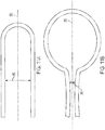
- the reversible support includes two interfaces, as shown in Figure 7A and 7B.
- Figure 7A shows a reversible support 140 with a support component 142 and an articulated component 144 that form two interfaces 146, 148.
- Figure 7A illustrates the reversible support when the cover substrate has a first radius of curvature.
- Figure 7B shows the reversible support when the cover substrate is dynamically bent to have a second radius of curvature.
- the materials at the two interfaces could be adhered to one another or may be separate components (as shown in Figures 8A and 8B , respectively).
- the articulated component 144 is adhered to the support component 142.
- the articulated component 144 is adhered to the cover substrate 120.
- the reversible support shown in these embodiments may be made from a metallic or polymeric (e.g., plastic and/or rubber) material.
- the reversible support may be a spring (which may be a steel spring).
- the reversible support may be a corrugated or accordion shaped material such as a mesh polymer.
- the reversible support can provide continuous or regular support to the cover substrate when the cover substrate is dynamically bent in a cycle.
- An automotive interior display system including such a reversible support can meet HIT requirements at any point in the cycle, including when the bend axis of the cover substrate is impacted during HIT.
- the reversible support is in contact with the entire second major surface of the cover substrate.
- the material for the reversible support is unlimited as long as it can dynamically bend the cover substrate along the cycle. In some embodiments, the material may be described as elastic.
- the bend axis is positioned along the first and second major surface of the cover substrate at a position along the width in a range from about 0.1*width to about 0.9*width (e.g., 0.2*width to about 0.9*width, 0.25*width to about 0.9*width, 0.3*width to about 0.9*width, 0.*width to about 0.9*width, 0.5*width to about 0.9*width, 0.6*width to about 0.9*width, 0.75*width to about 0.9*width, 0.1*width to about 0.8*width, 0.1*width to about 0.75* width, 0.1*width to about 0.6*width, 0.1*width to about 0.5*width, 0.25*width to about 0.75* width, or 0.4*width to about 0.6* width).
- 0.1*width to about 0.9*width e.g., 0.2*width to about 0.9*width, 0.25*width
- the bend axis is positioned along the first and second major surface of the cover substrate at a position along the length in a range from about 0.1*length to about 0.9* length (e.g., 0.2*length to about 0.9*length, 0.25*length to about 0.9*length, 0.3*length to about 0.9*length, 0.*length to about 0.9*length, 0.5*length to about 0.9*length, 0.6*length to about 0.9*length, 0.75*length to about 0.9*length, 0.1 *length to about 0.8* length, 0.1 *length to about 0.75* length, 0.1*length to about 0.6*length, 0.1*length to about 0.5* length, 0.25*length to about 0.75* length, or 0.4*length to about 0.6* length).
- 0.1*length to about 0.9* length e.g., 0.2*length to about 0.9*length, 0.25*length to about 0.9*length, 0.3*length to about 0.9*length, 0.*length to about 0.9*length, 0.5
- the automotive interior display system is capable of meeting HIT requirements.
- the deceleration of the impactor is 120 g (g-force) or less.
- the deceleration of the impactor is not greater than 80 g for any 3 ms interval over a time of impact.
- the cover substrate is substantially free of local bending at the impact location. In one or more specific embodiments, after the first major surface is impacted by an impactor at an impact location, the cover substrate bends at bend axis. In some embodiments, after the first major surface is impacted by an impactor at an impact location, the cover substrate is substantially free of anticlastic effects.
- the cover substrate is capable of being dynamically bent along the bend axis for more than 100 cycles (e.g., about 500 cycles or more, about 1000 cycles or more, about 2000 cycles or more, about 5000 cycles or more, about 10,000 cycles or more, about 20,000 cycles or more, about 30,000 cycles or more, about 40,000 cycles or more ,about 50,000 cycles or more, about 60,000 cycles or more, about 70,000 cycles or more, about 80,000 cycles or more, about 90,000 cycles or more, about 100,000 cycles or more, about 150,000 cycles or more, about 200,000 cycles or more, or about 500,000 cycles or more), without experiencing failure (e.g., fracture or breakage).
- 100 cycles e.g., about 500 cycles or more, about 1000 cycles or more, about 2000 cycles or more, about 5000 cycles or more, about 10,000 cycles or more, about 20,000 cycles or more, about 30,000 cycles or more, about 40,000 cycles or more ,about 50,000 cycles or more, about 60,000 cycles or more, about 70,000 cycles or more, about 80,000 cycles or more, about 90,000 cycles
- the cover substrate is capable of being dynamically bent along the bend axis for more than 100 cycles (e.g., about 500 cycles or more, about 1000 cycles or more, about 2000 cycles or more, about 5000 cycles or more, about 10,000 cycles or more, about 20,000 cycles or more, about 30,000 cycles or more, about 40,000 cycles or more ,about 50,000 cycles or more, about 60,000 cycles or more, about 70,000 cycles or more, about 80,000 cycles or more, about 90,000 cycles or more, about 100,000 cycles or more, about 150,000 cycles or more, about 200,000 cycles or more, or about 500,000 cycles or more), without delamination between the cover substrate system and the display.
- 100 cycles e.g., about 500 cycles or more, about 1000 cycles or more, about 2000 cycles or more, about 5000 cycles or more, about 10,000 cycles or more, about 20,000 cycles or more, about 30,000 cycles or more, about 40,000 cycles or more ,about 50,000 cycles or more, about 60,000 cycles or more, about 70,000 cycles or more, about 80,000 cycles or more, about 90,000 cycles or
- the display is dynamically bendable.
- the reversible support dynamically bends display as it dynamically bends the cover substrate along the bend axis in the cycle.
- the display is dynamically bent along the cycle.
- the display may be a liquid crystal display, an organic light-emitting diode (OLED) display, a transmissive display or other display.
- the display is curved in an initial state and has a first radius of curvature, and can be dynamically bent to have a smaller radius of curvature or larger radius of curvature than first radius of curvature.
- a cover substrate exhibits the same curvature in an initial state and can be dynamically bent with the display.
- the display permanently curved, and the cover substrate is dynamically bendable in an area that is not disposed over the display.
- the dynamically bendable automotive interior display system includes a first frame comprising a first frame surface, a second frame surface opposing the first frame surface, and a frame edge with a thickness defined as the distance between the first frame surface and the second frame surface, a frame width defined as a first dimension of one of the first or second frame surfaces orthogonal to the frame thickness, and a frame length defined as a second dimension of one of the first or second frame surfaces orthogonal to both the frame thickness and the frame width; a frame opening extending from the first frame surface to the second frame surface and surrounded by an interior surface connecting the first frame surface and the second frame surface.
- the display 150 is disposed in the frame opening within the interior surface.
- the dynamically bendable cover substrate described herein is disposed on the first frame surface and over the display.
- the reversible support is attached to at least a portion of the second frame surface and dynamically bends the cover substrate along the bend axis in a cycle from a first radius of curvature to a second radius of curvature and from the second radius of curvature to the first radius of curvature.
- the display system can include more than one frame.
- the system may include a second frame (as shown in Figure 3A ) with a first frame surface, a second frame surface opposing the first frame surface, and a frame edge with a thickness defined as the distance between the first frame surface and the second frame surface, a frame width defined as a first dimension of one of the first or second frame surfaces orthogonal to the frame thickness, and a frame length defined as a second dimension of one of the first or second frame surfaces orthogonal to both the frame thickness and the frame width; a frame opening extending from the first frame surface to the second frame surface and surrounded by an interior surface connecting the first frame surface and the second frame surface.
- a second display may be disposed in the frame opening within the interior surface of the second frame.
- the reversible support is attached to the second frame surface of the first frame and the second frame surface of the second frame, and positioned between the first frame and the second frame.
- the bend axis is positioned between the first frame and the second frame.
- Figures 9A and 9B show a perspective front view of a dynamically automotive interior display system with the cover substrate having a cold-bent portion and being dynamically bent from a first radius of curvature to a second radius of curvature toward a passenger, and toward a driver, respectively.
- the system 200 includes a cover substrate with that is dynamically bent from a first radius of curvature to a second radius of curvature along a bend axis 201.
- a display 202 is disposed under the portion of the cover substrate that is not dynamically bent and a display (not shown) may be disposed on a portion of the cover substrate that is dynamically bent.
- the system 210 includes a cover substrate with that is dynamically bent from a first radius of curvature to a second radius of curvature along a bend axis 211.
- a display 212 is disposed under the portion of the cover substrate that is dynamically bent and an optional display (not shown) may be disposed on a portion of the cover substrate that is not dynamically bent.
- Figures 10A-10C show different views of a cover substrate 300 that has a first major surface 301, an opposing second major surface 302, and more than one curved portion (e.g., 310, 312, 314, 316 and 318).
- the curved portions form concave and convex surfaces from the point of view of the first major surface 301.
- curved portions 310, 314 and 316 form concave shapes and curved portions 312 and 318 form convex shapes.
- the number of curved portions and/or shapes formed (convex or concave) and combinations and order of such curved portions and shapes is unlimited.
- the curved portions are separated by a substantially uncurved (or flat) 320.
- the flat portion manages competing local stresses caused the adjacent curvatures (especially where the adjacent curvatures are in opposing directions).
- the flat portion has a length in a range from about 10 mm to about 100 mm, from about 20 mm to about 100 mm, from about 30 mm to about 100 mm, from about 40 mm to about 100 mm, from about 50 mm to about 100 mm, from about 60 mm to about 100 mm, from about 10 mm to about 90 mm, from about 10 mm to about 80 mm, from about 10 mm to about 70 mm, from about 10 mm to about 60 mm, from about 10 mm to about 50 mm, or from about 25 mm to about 75 mm.
- the curved substrate has more than one bend axis (e.g., two or more or three or more bend axes).
- Figures 10A-10C has two bend axes 330, 340.
- the bend axes 330, 340 are embodiments, the portion of the cover substrate that is dynamically bent and the substantially vertical; however, they may be horizontal, diagonal or any other direction.
- the minor surface 326 at the portion of the covers substrate that is dynamically bent are located outside the area of the cover substrate subject to the type of impacts measured by HIT.
- the minor surface 326 at the portion of the covers substrate that is dynamically bent are located within the area of the cover substrate subject to the type of impacts measured by HIT; however, the reversible support is collapsible when impacted.
- the bend axis or axes are positioned to reduce the stress on the minor surface of the cover substrate that is dynamically bent.
- the bend axis or axes may be positioned along the shortest length or width dimension of the cover substrate to minimize the stress exerted on the cover substrate.
- the curved substrate 300 may be dynamically bent around a bend axis from a flat shape to a convex shape and back to flat shape, from a flat shape to the concave shape and back to flat shape, from a concave shape to a convex shape and back to a concave shape, from a convex shape to a concave shape and back to a convex shape, from a concave shape to a flat shape back to a concave shape, from a convex shape to a flat shape and back to a convex shape, from a concave shape to a flat shape to a convex shape, or from a convex shape to a flat shape to a concave shape in a single cycle.
- the cover substrate may be foldable and may dynamically bend around a bend axis 350 such that the first radius of curvature is flat when measured from one of the first or second major surface, and the second radius of curvature (measured from the same first or second major surface from which the first radius of curvature is measured) is less than 500 mm, less than 400 mm, less than 300 mm, less than 200 mm, less than 100 mm or less than 50 mm.
- an underlying display is dynamically bent as the cover substrate is bent.
- the first and second radii of curvature may be changed depending on the distance 360 desired between the folded portions of the cover substrate.
- the second radius of curvature may be minimized but the distance 360 may be increased, as shown in Figure 11A .
- the second radius of curvature may be reduced but the distance 360 may be increased, as shown in Figure 11B .
- the cover substrate can dynamically bent along the bend axis to form such shapes for more than 100 cycles (e.g., about 500 cycles or more, about 1000 cycles or more, about 2000 cycles or more, about 5000 cycles or more, about 10,000 cycles or more, about 20,000 cycles or more, about 30,000 cycles or more, about 40,000 cycles or more ,about 50,000 cycles or more, about 60,000 cycles or more, about 70,000 cycles or more, about 80,000 cycles or more, about 90,000 cycles or more, about 100,000 cycles or more, about 150,000 cycles or more, about 200,000 cycles or more, or about 500,000 cycles or more), without experiencing failure (e.g., fracture or breakage).
- a failure e.g., fracture or breakage
- the cover substrate is capable of being dynamically bent along the bend axis for more than 100 cycles (e.g., about 500 cycles or more, about 1000 cycles or more, about 2000 cycles or more, about 5000 cycles or more, about 10,000 cycles or more, about 20,000 cycles or more, about 30,000 cycles or more, about 40,000 cycles or more ,about 50,000 cycles or more, about 60,000 cycles or more, about 70,000 cycles or more, about 80,000 cycles or more, about 90,000 cycles or more, about 100,000 cycles or more, about 150,000 cycles or more, about 200,000 cycles or more, or about 500,000 cycles or more), without delamination between the cover substrate system and the display.
- 100 cycles e.g., about 500 cycles or more, about 1000 cycles or more, about 2000 cycles or more, about 5000 cycles or more, about 10,000 cycles or more, about 20,000 cycles or more, about 30,000 cycles or more, about 40,000 cycles or more ,about 50,000 cycles or more, about 60,000 cycles or more, about 70,000 cycles or more, about 80,000 cycles or more, about 90,000 cycles or
- One or more displays may be positioned adjacent the second major surface 302.
- the displays may be dynamically bent as the cover substrate is dynamically bent.
- dynamically bending the cover substrate causes the underlying display to dynamically bend around the bend axis around which the cover system is bent.
- the portions of the cover glass that are bent and not bent may be identical in size and shape or may be different in size and/or shape from one another.
- the portion of the cover substrate that is dynamically bent may have greater length and width dimensions than the portion of the cover substrate that is not dynamically bent.
- the minor surface 326 may have a profile that is not planar.
- the minor surface may have a 2.5D shape, a "C" shape, or 0.65D shape, or may include one or more chamfers.
Claims (9)
- Anzeigesystem (100), umfassend:einen ersten Rahmen, der eine erste Rahmenfläche, eine der ersten Rahmenfläche entgegengesetzte zweite Rahmenfläche und einen Rahmenrand mit einer Dicke umfasst, die als der Abstand zwischen der ersten Rahmenfläche und der zweiten Rahmenfläche definiert ist, einer Rahmenbreite, die als die erste Abmessung einer der ersten oder zweiten Rahmenfläche orthogonal zur Rahmendicke definiert ist, und einer Rahmenlänge, die als eine zweite Abmessung einer der ersten oder zweiten Rahmenfläche orthogonal zu sowohl der Rahmendicke als auch der Rahmenbreite definiert ist; einer Rahmenöffnung, die sich von der ersten Rahmenfläche zur zweiten Rahmenfläche erstreckt und von einer Innenfläche umgeben ist, welche die erste Rahmenfläche und die zweite Rahmenfläche verbindet;eine Anzeige (150), die in der Rahmenöffnung innerhalb der Innenfläche angeordnet ist;ein Abdeckungssubstrat (120), das auf der ersten Rahmenfläche und über der Anzeige (150) angeordnet ist, wobei das Abdeckungssubstrat (150) eine erste größere Fläche (121), eine der ersten größeren Fläche (121) entgegengesetzte zweite größere Fläche (22) und eine kleinere Fläche (126), welche die erste größere Fläche (121) und die zweite größere Fläche (122) verbindet, eine Dicke, die als ein Abstand zwischen der ersten größeren Fläche (121) und der zweiten größeren Fläche (122) definiert ist, eine Breite, die als eine erste Abmessung der ersten oder zweiten größeren Fläche (121, 122) orthogonal zur Dicke definiert ist, eine Länge, die als zweite Abmessung der ersten oder zweiten größeren Fläche orthogonal sowohl zu der Dicke als auch der Breite definiert ist, und eine Biegeachse (125) hat; undeine reversible Halterung (140), die an zumindest einem Abschnitt der zweiten Rahmenfläche angebracht ist und das Abdeckungssubstrat (120) dynamisch entlang der Biegeachse (125) in einem Zyklus von einem ersten Krümmungsradius zu einem zweiten Krümmungsradius und vom zweiten Krümmungsradius zum ersten Krümmungsradius biegt, dadurch gekennzeichnet, dass das Anzeigesystem darüber hinaus einen zweiten Rahmen umfasst, der eine erste Rahmenfläche, eine der ersten Rahmenfläche entgegengesetzte zweite Rahmenfläche und einen Rahmenrand mit einer Dicke umfasst, die als der Abstand zwischen der ersten Rahmenfläche und der zweiten Rahmenfläche definiert ist, einer Rahmenbreite, die als erste Abmessung der ersten oder zweiten Rahmenfläche orthogonal zur Rahmendicke definiert ist, und einer Rahmenlänge, die als zweite Abmessung der ersten oder zweiten Rahmenfläche orthogonal sowohl zur Rahmendicke als auch zu der Rahmenbreite definiert ist; einer Rahmenöffnung, die sich von der ersten Rahmenfläche zur zweiten Rahmenfläche erstreckt und von einer Innenfläche umgeben ist, welche die erste Rahmenfläche und die zweite Rahmenfläche verbindet; undeine zweite Anzeige, die in der Rahmenöffnung innerhalb der Innenfläche des zweiten Rahmens angeordnet ist,wobei die reversible Halterung (140) an der zweiten Rahmenfläche des ersten Rahmens und an der zweiten Rahmenfläche des zweiten Rahmens angebracht ist und sich zwischen dem ersten Rahmen und dem zweiten Rahmen befindet.
- Anzeigesystem nach Anspruch 1, wobei sich die Biegeachse (125) zwischen dem ersten Rahmen und dem zweiten Rahmen befindet.
- Anzeigesystem nach Anspruch 1, wobei das Abdeckungssubstrat (120) mehrere Biegeachsen (125, 330, 340) umfasst.
- Anzeigesystem nach einem der Ansprüche 1 bis 3, wobei, wenn ein Schlagkörper mit einer Masse von 6,8 kg auf die erste größere Fläche mit einer Schlaggeschwindigkeit von 5,35 m/s bis 6,69 m/s auftrifft, die Abbremsung des Schlagkörpers 120 g "g-Kraft" oder weniger beträgt.
- Fahrzeuginnenraumsystem nach Anspruch 4, wobei die Abbremsung des Schlagkörpers für jeden Zeitraum von 3 ms über eine Auftreffzeit nicht mehr als 80 g beträgt.
- Anzeigesystem nach einem der Ansprüche 1 bis 5, wobei der erste Krümmungsradius ca. 10.000 mm oder weniger beträgt, wobei das Abdeckungssubstrat (120) einen kaltgebogenen Glasartikel umfasst, oder das Abdeckungssubstrat (120) einen warmgeformten Glasartikel umfasst.
- Anzeigesystem nach einem der Ansprüche 1 bis 6, wobei die reversible Halterung (140) eine Kontaktfläche umfasst und 50 % oder mehr der Kontaktfläche mit der zweiten größeren Fläche (122) in Kontakt sind.
- Anzeigesystem nach einem der Ansprüche 1 bis 7, darüber hinaus ein Klebemittel zwischen dem Abdeckungssubstrat und der ersten Rahmenfläche umfassend.
- Anzeigesystem nach einem der Ansprüche 1 bis 8, darüber hinaus ein Klebemittel zwischen dem Abdeckungssubstrat (120) und der Anzeige (150) umfassend.
Priority Applications (1)
| Application Number | Priority Date | Filing Date | Title |
|---|---|---|---|
| EP21192988.0A EP3939819A1 (de) | 2018-12-10 | 2019-12-09 | Dynamisch biegbare innenanzeigesysteme für kraftfahrzeuge |
Applications Claiming Priority (4)
| Application Number | Priority Date | Filing Date | Title |
|---|---|---|---|
| US201862777236P | 2018-12-10 | 2018-12-10 | |
| US201962789513P | 2019-01-07 | 2019-01-07 | |
| US201962789888P | 2019-01-08 | 2019-01-08 | |
| PCT/US2019/065199 WO2020123367A1 (en) | 2018-12-10 | 2019-12-09 | Dynamically bendable automotive interior display systems |
Related Child Applications (2)
| Application Number | Title | Priority Date | Filing Date |
|---|---|---|---|
| EP21192988.0A Division-Into EP3939819A1 (de) | 2018-12-10 | 2019-12-09 | Dynamisch biegbare innenanzeigesysteme für kraftfahrzeuge |
| EP21192988.0A Division EP3939819A1 (de) | 2018-12-10 | 2019-12-09 | Dynamisch biegbare innenanzeigesysteme für kraftfahrzeuge |
Publications (2)
| Publication Number | Publication Date |
|---|---|
| EP3684640A1 EP3684640A1 (de) | 2020-07-29 |
| EP3684640B1 true EP3684640B1 (de) | 2021-09-29 |
Family
ID=69063875
Family Applications (2)
| Application Number | Title | Priority Date | Filing Date |
|---|---|---|---|
| EP21192988.0A Pending EP3939819A1 (de) | 2018-12-10 | 2019-12-09 | Dynamisch biegbare innenanzeigesysteme für kraftfahrzeuge |
| EP19832500.3A Active EP3684640B1 (de) | 2018-12-10 | 2019-12-09 | Dynamisch biegbare fahrzeuginnenraumanzeigesysteme |
Family Applications Before (1)
| Application Number | Title | Priority Date | Filing Date |
|---|---|---|---|
| EP21192988.0A Pending EP3939819A1 (de) | 2018-12-10 | 2019-12-09 | Dynamisch biegbare innenanzeigesysteme für kraftfahrzeuge |
Country Status (7)
| Country | Link |
|---|---|
| US (1) | US11116098B2 (de) |
| EP (2) | EP3939819A1 (de) |
| JP (1) | JP2022511579A (de) |
| KR (1) | KR20210102836A (de) |
| CN (2) | CN111556820A (de) |
| TW (1) | TW202105121A (de) |
| WO (2) | WO2020123368A1 (de) |
Families Citing this family (8)
| Publication number | Priority date | Publication date | Assignee | Title |
|---|---|---|---|---|
| CN111556820A (zh) * | 2018-12-10 | 2020-08-18 | 康宁公司 | 可动态弯折的汽车内部显示系统 |
| US20220011478A1 (en) | 2020-07-09 | 2022-01-13 | Corning Incorporated | Textured region of a substrate to reduce specular reflectance incorporating surface features with an elliptical perimeter or segments thereof, and method of making the same |
| WO2022039969A1 (en) * | 2020-08-19 | 2022-02-24 | Corning Incorporated | Glass article for vehicle interior system having a bendable display unit |
| CN113327514B (zh) * | 2021-05-25 | 2022-09-09 | 上海天马微电子有限公司 | 显示装置和交通载具 |
| TWI776594B (zh) * | 2021-07-14 | 2022-09-01 | 和碩聯合科技股份有限公司 | 可調整視角的儀表裝置 |
| KR20240038997A (ko) * | 2021-07-28 | 2024-03-26 | 코닝 인코포레이티드 | 개선된 헤드 충격 성능을 갖는 차량 내부 시스템용 벤딩 가능한 유리 물품 |
| WO2023096805A1 (en) * | 2021-11-29 | 2023-06-01 | Corning Incorporated | Glass article with discontinuous adhesive layer and method of preparing same |
| WO2024010143A1 (ko) * | 2022-07-06 | 2024-01-11 | 엘지전자 주식회사 | 변형가능한 디스플레이 디바이스 |
Family Cites Families (72)
| Publication number | Priority date | Publication date | Assignee | Title |
|---|---|---|---|---|
| JPH10207389A (ja) * | 1997-01-20 | 1998-08-07 | Sony Corp | 画像表示端末 |
| DE19959084B4 (de) * | 1999-12-08 | 2005-05-12 | Schott Ag | Organisches LED-Display und Verfahren zu seiner Herstellung |
| JP2006072115A (ja) * | 2004-09-03 | 2006-03-16 | Fuji Photo Film Co Ltd | 画像表示装置 |
| KR101814683B1 (ko) * | 2006-09-06 | 2018-01-05 | 더 보오드 오브 트러스티스 오브 더 유니버시티 오브 일리노이즈 | 2차원 인장 가능하고 구부릴 수 있는 장치 |
| KR20110029089A (ko) * | 2009-09-14 | 2011-03-22 | 유상규 | 표시영역 가변형 디스플레이 장치 |
| KR101879615B1 (ko) | 2011-11-23 | 2018-07-19 | 삼성전자주식회사 | 디스플레이 장치 및 그의 제어 방법 |
| KR102206456B1 (ko) * | 2014-01-02 | 2021-01-21 | 엘지전자 주식회사 | 디스플레이 장치 |
| US9321677B2 (en) * | 2014-01-29 | 2016-04-26 | Corning Incorporated | Bendable glass stack assemblies, articles and methods of making the same |
| KR102276108B1 (ko) | 2014-05-26 | 2021-07-12 | 삼성전자 주식회사 | 폴더형 표시부를 가지는 전자 장치 및 이의 운영 방법 |
| US10434847B2 (en) | 2014-08-07 | 2019-10-08 | Semiconductor Energy Laboratory Co., Ltd. | Display device and driving support system |
| KR102209514B1 (ko) * | 2014-09-05 | 2021-01-29 | 엘지전자 주식회사 | 이동 단말기 |
| KR20160031363A (ko) | 2014-09-12 | 2016-03-22 | 삼성전자주식회사 | 유연성 디스플레이 소자를 포함하는 전자 장치 |
| US9606625B2 (en) | 2014-10-13 | 2017-03-28 | Immersion Corporation | Haptically-enabled deformable device with rigid component |
| DE102014016323B4 (de) * | 2014-11-03 | 2021-11-25 | Audi Ag | Anzeigevorrichtung für einen Kraftwagen, Verfahren zum Betreiben einer Anzeigevorrichtung und Kraftwagen mit einer Anzeigevorrichtung |
| DE102014016328B3 (de) | 2014-11-03 | 2016-03-17 | Audi Ag | Verfahren zum Betreiben einer Anzeigevorrichtung, Anzeigevorrichtung für einen Kraftwagen und Kraftwagen mit einer Anzeigenvorrichtung |
| KR20160056763A (ko) | 2014-11-10 | 2016-05-20 | 주식회사 다이아벨 | 밴딩 힌지 장치 및 이를 구비하는 전자기기 |
| KR102288437B1 (ko) | 2014-11-21 | 2021-08-10 | 삼성전자주식회사 | 접을 수 있는 전자 장치 |
| US10086762B2 (en) | 2014-12-10 | 2018-10-02 | Lg Electronics Inc. | Vehicle display device and vehicle comprising same |
| KR102374643B1 (ko) * | 2015-01-28 | 2022-03-15 | 삼성디스플레이 주식회사 | 가변형 디스플레이 장치 |
| KR102309091B1 (ko) | 2015-03-02 | 2021-10-07 | 삼성디스플레이 주식회사 | 오토모티브 표시 장치 |
| DE102015005365A1 (de) | 2015-04-25 | 2016-10-27 | Audi Ag | Anzeigevorrichtung für einen Kraftwagen, Verfahren zum Betreiben einer Anzeigevorrichtung und Kraftwagen mit einer Anzeigevorrichtung |
| KR102414855B1 (ko) | 2015-04-30 | 2022-07-01 | 삼성전자주식회사 | 플렉시블 전자 장치 |
| EP3310209A4 (de) | 2015-06-16 | 2019-03-27 | Amx Llc | Einziehbare anzeige |
| US9947882B2 (en) | 2015-09-25 | 2018-04-17 | Apple Inc. | Electronic devices with robust flexible displays |
| KR102423447B1 (ko) | 2015-10-22 | 2022-07-21 | 삼성전자 주식회사 | 벤디드 디스플레이를 구비한 전자 장치 및 그 제어 방법 |
| KR20170064360A (ko) | 2015-12-01 | 2017-06-09 | 삼성전자주식회사 | 휘어진 디스플레이를 포함하는 전자 장치 |
| CN205239166U (zh) | 2015-12-24 | 2016-05-18 | 深圳市柔宇科技有限公司 | 汽车中控台及控制面板 |
| KR102459831B1 (ko) | 2015-12-28 | 2022-10-28 | 삼성전자주식회사 | 플렉서블 디스플레이를 포함하는 전자 장치 및 그 동작 방법 |
| CN108475692B (zh) | 2015-12-28 | 2022-07-22 | 3M创新有限公司 | 具有流体腔设计的柔性电子设备 |
| KR102489592B1 (ko) | 2015-12-31 | 2023-01-18 | 엘지디스플레이 주식회사 | 플렉서블 표시장치 |
| KR20180101514A (ko) | 2016-01-15 | 2018-09-12 | 코닝 인코포레이티드 | 절첩가능 전자 디바이스 조립체들 및 그를 위한 커버 요소들 |
| US10328865B2 (en) | 2016-01-27 | 2019-06-25 | Panasonic Automotive Systems Company Of America, Division Of Panasonic Corporation Of North America | Flexible display framework for cars |
| US20170213872A1 (en) | 2016-01-27 | 2017-07-27 | Semiconductor Energy Laboratory Co., Ltd. | Display device |
| KR102505878B1 (ko) * | 2016-01-29 | 2023-03-06 | 삼성디스플레이 주식회사 | 플렉서블 디스플레이 장치 |
| KR102509088B1 (ko) | 2016-03-14 | 2023-03-10 | 삼성디스플레이 주식회사 | 표시 장치 |
| KR102454824B1 (ko) | 2016-03-25 | 2022-10-18 | 삼성디스플레이 주식회사 | 플렉서블 표시장치 |
| CN108779025B (zh) | 2016-04-01 | 2021-08-10 | 日本电气硝子株式会社 | 化学强化玻璃 |
| KR102625286B1 (ko) | 2016-04-22 | 2024-01-17 | 삼성디스플레이 주식회사 | 플렉서블 표시장치 |
| CN205905907U (zh) | 2016-07-12 | 2017-01-25 | 同济大学 | 一种可自动或手动伸缩翻转的显示屏机构 |
| KR102499448B1 (ko) | 2016-07-21 | 2023-02-15 | 삼성전자주식회사 | 힌지 구조를 포함하는 전자 장치 |
| DE102016215546A1 (de) | 2016-08-18 | 2018-02-22 | Faurecia Innenraum Systeme Gmbh | Verfahren zur Herstellung eines Fahrzeuginnenverkleidungsteils und Fahrzeuginnenverkleidungsteil |
| KR102614333B1 (ko) | 2016-09-08 | 2023-12-19 | 삼성디스플레이 주식회사 | 표시장치 |
| KR102636648B1 (ko) | 2016-09-13 | 2024-02-15 | 삼성전자주식회사 | 플렉서블 디스플레이 전자 장치 |
| KR102578589B1 (ko) | 2016-09-30 | 2023-09-14 | 엘지디스플레이 주식회사 | 플렉서블 표시장치 |
| KR20180039342A (ko) | 2016-10-10 | 2018-04-18 | 삼성전자주식회사 | 플렉서블 디스플레이를 가지는 전자 장치 |
| KR102649729B1 (ko) | 2016-11-02 | 2024-03-22 | 삼성디스플레이 주식회사 | 표시장치 |
| JP2018081186A (ja) * | 2016-11-16 | 2018-05-24 | 株式会社半導体エネルギー研究所 | 情報処理装置、表示装置および電子機器 |
| KR20180062273A (ko) * | 2016-11-30 | 2018-06-08 | 엘지디스플레이 주식회사 | 폴더블 표시 장치 |
| KR20180063940A (ko) | 2016-12-02 | 2018-06-14 | 삼성디스플레이 주식회사 | 저곡률로 굽힘이 가능한 플렉시블 글라스 물품 및 그 제조 방법 |
| KR102653367B1 (ko) | 2016-12-08 | 2024-04-02 | 삼성전자 주식회사 | 벤디드 디스플레이를 구비한 전자 장치 및 그 제어 방법 |
| TW201830102A (zh) * | 2016-12-14 | 2018-08-16 | 美商3M新設資產公司 | 分段保護顯示膜 |
| KR102516353B1 (ko) | 2016-12-28 | 2023-04-03 | 엘지디스플레이 주식회사 | 플렉서블 표시장치 및 그 제조 방법 |
| US10211416B2 (en) | 2016-12-28 | 2019-02-19 | Shanghai Tianma AM-OLED Co., Ltd. | Flexible display panel, fabrication method, and flexible display apparatus |
| KR102597750B1 (ko) | 2016-12-28 | 2023-11-07 | 엘지디스플레이 주식회사 | 플렉서블 표시장치 |
| KR102077696B1 (ko) | 2017-01-03 | 2020-02-14 | 코닝 인코포레이티드 | 만곡된 커버 유리 및 디스플레이 또는 터치 패널을 갖는 차량 인테리어 시스템 및 이를 형성시키는 방법 |
| DE102017200949B4 (de) * | 2017-01-20 | 2019-05-02 | Audi Ag | Kombiinstrument mit verformbarer Anzeige und Fahrzeug mit einem Kombiinstrument |
| US10303218B2 (en) * | 2017-02-01 | 2019-05-28 | Apple Inc. | Foldable cover and display for an electronic device |
| KR102309412B1 (ko) | 2017-04-19 | 2021-10-06 | 엘지전자 주식회사 | 차량에 구비된 차량 제어 장치 및 차량의 제어방법 |
| KR102426694B1 (ko) | 2017-05-02 | 2022-07-29 | 삼성전자주식회사 | 플렉서블 디스플레이를 포함하는 전자 장치 |
| DE102017207452A1 (de) * | 2017-05-03 | 2018-11-08 | Faurecia Innenraum Systeme Gmbh | Verfahren und Formwerkzeug zum Herstellen eines Bauteils für die Verwendung in einem Fahrzeuginnenraum |
| KR102324508B1 (ko) | 2017-06-28 | 2021-11-09 | 엘지디스플레이 주식회사 | 접이식 디스플레이 장치 |
| US10943529B2 (en) | 2017-08-28 | 2021-03-09 | Apple Inc. | Electronic devices with flexible displays |
| US10559252B2 (en) * | 2017-09-07 | 2020-02-11 | Sakai Display Products Corporation | Display apparatus |
| KR102553983B1 (ko) | 2017-11-20 | 2023-07-11 | 현대자동차주식회사 | 곡면 디스플레이장치 및 그 제조방법 |
| KR102489830B1 (ko) | 2017-12-29 | 2023-01-18 | 엘지디스플레이 주식회사 | 표시장치 |
| KR102487389B1 (ko) | 2018-01-30 | 2023-01-11 | 삼성전자주식회사 | 제스쳐를 이용하여 화면을 제어하기 위한 폴더블 전자 장치 및 방법 |
| CN108519831B (zh) | 2018-03-05 | 2022-01-14 | 努比亚技术有限公司 | 一种弯折伸缩机构 |
| CN108399863B (zh) | 2018-03-22 | 2020-08-21 | 京东方科技集团股份有限公司 | 一种柔性显示装置及其驱动方法 |
| CN108550587B (zh) | 2018-06-05 | 2020-08-11 | 京东方科技集团股份有限公司 | 柔性显示基板及其制作方法、柔性显示装置 |
| US10642318B1 (en) | 2018-09-14 | 2020-05-05 | Apple Inc. | Planar hinge assembly |
| CN111556820A (zh) * | 2018-12-10 | 2020-08-18 | 康宁公司 | 可动态弯折的汽车内部显示系统 |
| CN109743421B (zh) | 2018-12-29 | 2021-04-23 | Oppo广东移动通信有限公司 | 电子设备 |
-
2019
- 2019-12-09 CN CN201980005733.5A patent/CN111556820A/zh active Pending
- 2019-12-09 WO PCT/US2019/065203 patent/WO2020123368A1/en active Application Filing
- 2019-12-09 JP JP2020522802A patent/JP2022511579A/ja active Pending
- 2019-12-09 US US16/877,712 patent/US11116098B2/en active Active
- 2019-12-09 EP EP21192988.0A patent/EP3939819A1/de active Pending
- 2019-12-09 EP EP19832500.3A patent/EP3684640B1/de active Active
- 2019-12-09 CN CN201990000352.3U patent/CN214083864U/zh active Active
- 2019-12-09 KR KR1020207014072A patent/KR20210102836A/ko unknown
- 2019-12-09 WO PCT/US2019/065199 patent/WO2020123367A1/en unknown
- 2019-12-10 TW TW108145100A patent/TW202105121A/zh unknown
Also Published As
| Publication number | Publication date |
|---|---|
| TW202105121A (zh) | 2021-02-01 |
| CN111556820A (zh) | 2020-08-18 |
| EP3684640A1 (de) | 2020-07-29 |
| US20210029842A1 (en) | 2021-01-28 |
| US11116098B2 (en) | 2021-09-07 |
| CN214083864U (zh) | 2021-08-31 |
| WO2020123368A1 (en) | 2020-06-18 |
| JP2022511579A (ja) | 2022-02-01 |
| KR20210102836A (ko) | 2021-08-20 |
| WO2020123367A1 (en) | 2020-06-18 |
| EP3939819A1 (de) | 2022-01-19 |
Similar Documents
| Publication | Publication Date | Title |
|---|---|---|
| EP3684640B1 (de) | Dynamisch biegbare fahrzeuginnenraumanzeigesysteme | |
| US11586306B2 (en) | Vehicle interior systems having a curved cover glass and display or touch panel and methods for forming the same | |
| EP3867206B1 (de) | Verstärkte glasgegenstände mit verbessertem kopfaufschlagverhalten und automobilinterieursysteme damit | |
| TWI806897B (zh) | 用於顯示器的基於光導器的無電面板、相關的方法及載具內部系統 | |
| WO2020014064A1 (en) | Deadfront configured for color matching | |
| US20210255500A1 (en) | Cover glass with reinforcement for display or touch panels | |
| US20220089028A1 (en) | Automotive interior comprising deadfront configured for color matching | |
| WO2020112433A1 (en) | Dynamically adjustable display system and methods of dynamically adjusting a display | |
| US20230043205A1 (en) | Dynamically bendable automotive interior display systems | |
| US20230202300A1 (en) | Improved automotive display panels | |
| US20230192525A1 (en) | Cold-formed cover glass having compound curvature and/or multiple curvatures |
Legal Events
| Date | Code | Title | Description |
|---|---|---|---|
| STAA | Information on the status of an ep patent application or granted ep patent |
Free format text: STATUS: UNKNOWN |
|
| STAA | Information on the status of an ep patent application or granted ep patent |
Free format text: STATUS: THE INTERNATIONAL PUBLICATION HAS BEEN MADE |
|
| PUAI | Public reference made under article 153(3) epc to a published international application that has entered the european phase |
Free format text: ORIGINAL CODE: 0009012 |
|
| STAA | Information on the status of an ep patent application or granted ep patent |
Free format text: STATUS: REQUEST FOR EXAMINATION WAS MADE |
|
| 17P | Request for examination filed |
Effective date: 20200417 |
|
| AK | Designated contracting states |
Kind code of ref document: A1 Designated state(s): AL AT BE BG CH CY CZ DE DK EE ES FI FR GB GR HR HU IE IS IT LI LT LU LV MC MK MT NL NO PL PT RO RS SE SI SK SM TR |
|
| AX | Request for extension of the european patent |
Extension state: BA ME |
|
| RAP1 | Party data changed (applicant data changed or rights of an application transferred) |
Owner name: CORNING INCORPORATED |
|
| RIN1 | Information on inventor provided before grant (corrected) |
Inventor name: GROSS, TIMOTHY MICHAEL Inventor name: NATH, TORSTEN Inventor name: LAYOUNI, KHALED Inventor name: WEEKS, WENDELL PORTER |
|
| GRAP | Despatch of communication of intention to grant a patent |
Free format text: ORIGINAL CODE: EPIDOSNIGR1 |
|
| STAA | Information on the status of an ep patent application or granted ep patent |
Free format text: STATUS: GRANT OF PATENT IS INTENDED |
|
| DAV | Request for validation of the european patent (deleted) | ||
| DAX | Request for extension of the european patent (deleted) | ||
| INTG | Intention to grant announced |
Effective date: 20210423 |
|
| GRAS | Grant fee paid |
Free format text: ORIGINAL CODE: EPIDOSNIGR3 |
|
| GRAA | (expected) grant |
Free format text: ORIGINAL CODE: 0009210 |
|
| STAA | Information on the status of an ep patent application or granted ep patent |
Free format text: STATUS: THE PATENT HAS BEEN GRANTED |
|
| AK | Designated contracting states |
Kind code of ref document: B1 Designated state(s): AL AT BE BG CH CY CZ DE DK EE ES FI FR GB GR HR HU IE IS IT LI LT LU LV MC MK MT NL NO PL PT RO RS SE SI SK SM TR |
|
| REG | Reference to a national code |
Ref country code: GB Ref legal event code: FG4D |
|
| REG | Reference to a national code |
Ref country code: CH Ref legal event code: EP Ref country code: AT Ref legal event code: REF Ref document number: 1433909 Country of ref document: AT Kind code of ref document: T Effective date: 20211015 |
|
| REG | Reference to a national code |
Ref country code: DE Ref legal event code: R096 Ref document number: 602019008051 Country of ref document: DE |
|
| REG | Reference to a national code |
Ref country code: IE Ref legal event code: FG4D |
|
| REG | Reference to a national code |
Ref country code: LT Ref legal event code: MG9D |
|
| PG25 | Lapsed in a contracting state [announced via postgrant information from national office to epo] |
Ref country code: BG Free format text: LAPSE BECAUSE OF FAILURE TO SUBMIT A TRANSLATION OF THE DESCRIPTION OR TO PAY THE FEE WITHIN THE PRESCRIBED TIME-LIMIT Effective date: 20211229 Ref country code: LT Free format text: LAPSE BECAUSE OF FAILURE TO SUBMIT A TRANSLATION OF THE DESCRIPTION OR TO PAY THE FEE WITHIN THE PRESCRIBED TIME-LIMIT Effective date: 20210929 Ref country code: NO Free format text: LAPSE BECAUSE OF FAILURE TO SUBMIT A TRANSLATION OF THE DESCRIPTION OR TO PAY THE FEE WITHIN THE PRESCRIBED TIME-LIMIT Effective date: 20211229 Ref country code: FI Free format text: LAPSE BECAUSE OF FAILURE TO SUBMIT A TRANSLATION OF THE DESCRIPTION OR TO PAY THE FEE WITHIN THE PRESCRIBED TIME-LIMIT Effective date: 20210929 Ref country code: HR Free format text: LAPSE BECAUSE OF FAILURE TO SUBMIT A TRANSLATION OF THE DESCRIPTION OR TO PAY THE FEE WITHIN THE PRESCRIBED TIME-LIMIT Effective date: 20210929 Ref country code: SE Free format text: LAPSE BECAUSE OF FAILURE TO SUBMIT A TRANSLATION OF THE DESCRIPTION OR TO PAY THE FEE WITHIN THE PRESCRIBED TIME-LIMIT Effective date: 20210929 Ref country code: RS Free format text: LAPSE BECAUSE OF FAILURE TO SUBMIT A TRANSLATION OF THE DESCRIPTION OR TO PAY THE FEE WITHIN THE PRESCRIBED TIME-LIMIT Effective date: 20210929 |
|
| REG | Reference to a national code |
Ref country code: NL Ref legal event code: MP Effective date: 20210929 |
|
| REG | Reference to a national code |
Ref country code: AT Ref legal event code: MK05 Ref document number: 1433909 Country of ref document: AT Kind code of ref document: T Effective date: 20210929 |
|
| PG25 | Lapsed in a contracting state [announced via postgrant information from national office to epo] |
Ref country code: LV Free format text: LAPSE BECAUSE OF FAILURE TO SUBMIT A TRANSLATION OF THE DESCRIPTION OR TO PAY THE FEE WITHIN THE PRESCRIBED TIME-LIMIT Effective date: 20210929 Ref country code: GR Free format text: LAPSE BECAUSE OF FAILURE TO SUBMIT A TRANSLATION OF THE DESCRIPTION OR TO PAY THE FEE WITHIN THE PRESCRIBED TIME-LIMIT Effective date: 20211230 |
|
| PG25 | Lapsed in a contracting state [announced via postgrant information from national office to epo] |
Ref country code: AT Free format text: LAPSE BECAUSE OF FAILURE TO SUBMIT A TRANSLATION OF THE DESCRIPTION OR TO PAY THE FEE WITHIN THE PRESCRIBED TIME-LIMIT Effective date: 20210929 |
|
| PG25 | Lapsed in a contracting state [announced via postgrant information from national office to epo] |
Ref country code: IS Free format text: LAPSE BECAUSE OF FAILURE TO SUBMIT A TRANSLATION OF THE DESCRIPTION OR TO PAY THE FEE WITHIN THE PRESCRIBED TIME-LIMIT Effective date: 20220129 Ref country code: SK Free format text: LAPSE BECAUSE OF FAILURE TO SUBMIT A TRANSLATION OF THE DESCRIPTION OR TO PAY THE FEE WITHIN THE PRESCRIBED TIME-LIMIT Effective date: 20210929 Ref country code: RO Free format text: LAPSE BECAUSE OF FAILURE TO SUBMIT A TRANSLATION OF THE DESCRIPTION OR TO PAY THE FEE WITHIN THE PRESCRIBED TIME-LIMIT Effective date: 20210929 Ref country code: PT Free format text: LAPSE BECAUSE OF FAILURE TO SUBMIT A TRANSLATION OF THE DESCRIPTION OR TO PAY THE FEE WITHIN THE PRESCRIBED TIME-LIMIT Effective date: 20220131 Ref country code: PL Free format text: LAPSE BECAUSE OF FAILURE TO SUBMIT A TRANSLATION OF THE DESCRIPTION OR TO PAY THE FEE WITHIN THE PRESCRIBED TIME-LIMIT Effective date: 20210929 Ref country code: NL Free format text: LAPSE BECAUSE OF FAILURE TO SUBMIT A TRANSLATION OF THE DESCRIPTION OR TO PAY THE FEE WITHIN THE PRESCRIBED TIME-LIMIT Effective date: 20210929 Ref country code: ES Free format text: LAPSE BECAUSE OF FAILURE TO SUBMIT A TRANSLATION OF THE DESCRIPTION OR TO PAY THE FEE WITHIN THE PRESCRIBED TIME-LIMIT Effective date: 20210929 Ref country code: EE Free format text: LAPSE BECAUSE OF FAILURE TO SUBMIT A TRANSLATION OF THE DESCRIPTION OR TO PAY THE FEE WITHIN THE PRESCRIBED TIME-LIMIT Effective date: 20210929 Ref country code: CZ Free format text: LAPSE BECAUSE OF FAILURE TO SUBMIT A TRANSLATION OF THE DESCRIPTION OR TO PAY THE FEE WITHIN THE PRESCRIBED TIME-LIMIT Effective date: 20210929 Ref country code: AL Free format text: LAPSE BECAUSE OF FAILURE TO SUBMIT A TRANSLATION OF THE DESCRIPTION OR TO PAY THE FEE WITHIN THE PRESCRIBED TIME-LIMIT Effective date: 20210929 |
|
| REG | Reference to a national code |
Ref country code: DE Ref legal event code: R097 Ref document number: 602019008051 Country of ref document: DE |
|
| PG25 | Lapsed in a contracting state [announced via postgrant information from national office to epo] |
Ref country code: MC Free format text: LAPSE BECAUSE OF FAILURE TO SUBMIT A TRANSLATION OF THE DESCRIPTION OR TO PAY THE FEE WITHIN THE PRESCRIBED TIME-LIMIT Effective date: 20210929 Ref country code: DK Free format text: LAPSE BECAUSE OF FAILURE TO SUBMIT A TRANSLATION OF THE DESCRIPTION OR TO PAY THE FEE WITHIN THE PRESCRIBED TIME-LIMIT Effective date: 20210929 |
|
| PLBE | No opposition filed within time limit |
Free format text: ORIGINAL CODE: 0009261 |
|
| STAA | Information on the status of an ep patent application or granted ep patent |
Free format text: STATUS: NO OPPOSITION FILED WITHIN TIME LIMIT |
|
| 26N | No opposition filed |
Effective date: 20220630 |
|
| REG | Reference to a national code |
Ref country code: BE Ref legal event code: MM Effective date: 20211231 |
|
| PG25 | Lapsed in a contracting state [announced via postgrant information from national office to epo] |
Ref country code: LU Free format text: LAPSE BECAUSE OF NON-PAYMENT OF DUE FEES Effective date: 20211209 Ref country code: IE Free format text: LAPSE BECAUSE OF NON-PAYMENT OF DUE FEES Effective date: 20211209 |
|
| PG25 | Lapsed in a contracting state [announced via postgrant information from national office to epo] |
Ref country code: SI Free format text: LAPSE BECAUSE OF FAILURE TO SUBMIT A TRANSLATION OF THE DESCRIPTION OR TO PAY THE FEE WITHIN THE PRESCRIBED TIME-LIMIT Effective date: 20210929 Ref country code: BE Free format text: LAPSE BECAUSE OF NON-PAYMENT OF DUE FEES Effective date: 20211231 |
|
| PG25 | Lapsed in a contracting state [announced via postgrant information from national office to epo] |
Ref country code: IT Free format text: LAPSE BECAUSE OF FAILURE TO SUBMIT A TRANSLATION OF THE DESCRIPTION OR TO PAY THE FEE WITHIN THE PRESCRIBED TIME-LIMIT Effective date: 20210929 |
|
| PG25 | Lapsed in a contracting state [announced via postgrant information from national office to epo] |
Ref country code: CY Free format text: LAPSE BECAUSE OF FAILURE TO SUBMIT A TRANSLATION OF THE DESCRIPTION OR TO PAY THE FEE WITHIN THE PRESCRIBED TIME-LIMIT Effective date: 20210929 |
|
| P01 | Opt-out of the competence of the unified patent court (upc) registered |
Effective date: 20230527 |
|
| PG25 | Lapsed in a contracting state [announced via postgrant information from national office to epo] |
Ref country code: SM Free format text: LAPSE BECAUSE OF FAILURE TO SUBMIT A TRANSLATION OF THE DESCRIPTION OR TO PAY THE FEE WITHIN THE PRESCRIBED TIME-LIMIT Effective date: 20210929 Ref country code: HU Free format text: LAPSE BECAUSE OF FAILURE TO SUBMIT A TRANSLATION OF THE DESCRIPTION OR TO PAY THE FEE WITHIN THE PRESCRIBED TIME-LIMIT; INVALID AB INITIO Effective date: 20191209 |
|
| REG | Reference to a national code |
Ref country code: CH Ref legal event code: PL |
|
| PG25 | Lapsed in a contracting state [announced via postgrant information from national office to epo] |
Ref country code: LI Free format text: LAPSE BECAUSE OF NON-PAYMENT OF DUE FEES Effective date: 20221231 Ref country code: CH Free format text: LAPSE BECAUSE OF NON-PAYMENT OF DUE FEES Effective date: 20221231 |
|
| PGFP | Annual fee paid to national office [announced via postgrant information from national office to epo] |
Ref country code: GB Payment date: 20231108 Year of fee payment: 5 |
|
| PGFP | Annual fee paid to national office [announced via postgrant information from national office to epo] |
Ref country code: FR Payment date: 20231108 Year of fee payment: 5 Ref country code: DE Payment date: 20231108 Year of fee payment: 5 |
|
| PG25 | Lapsed in a contracting state [announced via postgrant information from national office to epo] |
Ref country code: MK Free format text: LAPSE BECAUSE OF FAILURE TO SUBMIT A TRANSLATION OF THE DESCRIPTION OR TO PAY THE FEE WITHIN THE PRESCRIBED TIME-LIMIT Effective date: 20210929 |