EP3684635B1 - Querträgersystem für ein kraftfahrzeug, das einen querführungsstab aufnimmt - Google Patents
Querträgersystem für ein kraftfahrzeug, das einen querführungsstab aufnimmt Download PDFInfo
- Publication number
- EP3684635B1 EP3684635B1 EP18749463.8A EP18749463A EP3684635B1 EP 3684635 B1 EP3684635 B1 EP 3684635B1 EP 18749463 A EP18749463 A EP 18749463A EP 3684635 B1 EP3684635 B1 EP 3684635B1
- Authority
- EP
- European Patent Office
- Prior art keywords
- cross member
- support
- spacer
- vehicle
- guide bar
- Prior art date
- Legal status (The legal status is an assumption and is not a legal conclusion. Google has not performed a legal analysis and makes no representation as to the accuracy of the status listed.)
- Active
Links
Images

Classifications
-
- B—PERFORMING OPERATIONS; TRANSPORTING
- B60—VEHICLES IN GENERAL
- B60G—VEHICLE SUSPENSION ARRANGEMENTS
- B60G21/00—Interconnection systems for two or more resiliently-suspended wheels, e.g. for stabilising a vehicle body with respect to acceleration, deceleration or centrifugal forces
- B60G21/02—Interconnection systems for two or more resiliently-suspended wheels, e.g. for stabilising a vehicle body with respect to acceleration, deceleration or centrifugal forces permanently interconnected
- B60G21/04—Interconnection systems for two or more resiliently-suspended wheels, e.g. for stabilising a vehicle body with respect to acceleration, deceleration or centrifugal forces permanently interconnected mechanically
- B60G21/05—Interconnection systems for two or more resiliently-suspended wheels, e.g. for stabilising a vehicle body with respect to acceleration, deceleration or centrifugal forces permanently interconnected mechanically between wheels on the same axle but on different sides of the vehicle, i.e. the left and right wheel suspensions being interconnected
- B60G21/051—Trailing arm twist beam axles
-
- B—PERFORMING OPERATIONS; TRANSPORTING
- B60—VEHICLES IN GENERAL
- B60G—VEHICLE SUSPENSION ARRANGEMENTS
- B60G2200/00—Indexing codes relating to suspension types
- B60G2200/20—Semi-rigid axle suspensions
-
- B—PERFORMING OPERATIONS; TRANSPORTING
- B60—VEHICLES IN GENERAL
- B60G—VEHICLE SUSPENSION ARRANGEMENTS
- B60G2200/00—Indexing codes relating to suspension types
- B60G2200/30—Rigid axle suspensions
- B60G2200/34—Stabilising mechanisms, e.g. for lateral stability
- B60G2200/341—Panhard rod
-
- B—PERFORMING OPERATIONS; TRANSPORTING
- B60—VEHICLES IN GENERAL
- B60G—VEHICLE SUSPENSION ARRANGEMENTS
- B60G2206/00—Indexing codes related to the manufacturing of suspensions: constructional features, the materials used, procedures or tools
- B60G2206/01—Constructional features of suspension elements, e.g. arms, dampers, springs
- B60G2206/20—Constructional features of semi-rigid axles, e.g. twist beam type axles
-
- B—PERFORMING OPERATIONS; TRANSPORTING
- B60—VEHICLES IN GENERAL
- B60G—VEHICLE SUSPENSION ARRANGEMENTS
- B60G2206/00—Indexing codes related to the manufacturing of suspensions: constructional features, the materials used, procedures or tools
- B60G2206/01—Constructional features of suspension elements, e.g. arms, dampers, springs
- B60G2206/80—Manufacturing procedures
- B60G2206/82—Joining
- B60G2206/8207—Joining by screwing
Definitions
- the present invention relates to a cross member system for a rear axle of a motor vehicle, equipped with a transverse guide bar support for this cross member, as well as a motor vehicle comprising such a cross member system.
- a known type of vehicle rear axle presented in particular by the document FR-A1-2892974 , comprises a crosspiece guided laterally by a transverse bar, also called a “Panhard” bar, which is arranged substantially horizontally.
- the guide bar fixed by pivots on one side to the vehicle body and on the other to one end of the cross member, by passing through the vehicle, guides this cross member in the transverse direction of the vehicle during the deflections of the cross member. suspension, by taking up lateral forces, in particular when cornering.
- the guide bar must be arranged substantially horizontally so as to remain close to the horizontal direction when the suspension moves.
- the end of the guide bar fixed to the cross member then exhibits a substantially vertical movement, with an almost zero horizontal component, which ensures good guidance of this cross member.
- cross member for reasons of space, another type of known cross member, presented in particular by the document JP-B2-4276566 , comprises a cross member comprising at one end a support formed from sheet metal, extending towards the rear, which is welded to the rear face of this cross member. The end of the support receives the pivot of the transverse guide bar, which is thus slightly offset from the cross member.
- the support made of sheet metal and welded to the cross member also made of sheet metal can pose problems of resistance, in particular at the level of the welding between the support and the cross member, in order to resist the lateral forces transmitted by the guide bar which can be significant.
- a relatively long support constitutes a lever arm multiplying the transverse force coming from the guide bar, by forming an alternating force torque in the direction of the bends, which is applied to the connection between the support and the cross member.
- the fatigue strength of the weld beads may be insufficient, in particular for welds on a deformable cross member made of sheet metal.
- the object of the present invention is in particular to avoid these drawbacks of the prior art.
- a motor vehicle rear axle cross member system comprising a sheet metal cross member forming in a section perpendicular to its length an open "U", equipped with a support having at its end a fixing intended to receive the. end of a guide bar of this cross member arranged in the transverse direction of the vehicle which is the direction perpendicular to the direction of travel of this vehicle, this system being remarkable in that it comprises at least two fixing screws which pass through the cross member and a spacer fitted between the two wings of the "U" section of this cross member, to secure the support to the cross member.
- the sleeper system according to the invention may further include one or more of the following features, which may be combined with one another.
- the cross has two flats each arranged on a wing of the "U" section, at the level of the spacer.
- the two flats are parallel, the spacer being fitted between these two flats.
- Parallel reference faces are thus formed, facilitating the production and installation of the spacer, and giving great stability to the support fixed above.
- the cross member system comprises two fixing screws aligned in the transverse direction of the vehicle, and each arranged on one side of the support.
- the support may comprise on each side a boss receiving a fixing screw which passes through this boss.
- each screw is fitted in a tubular insert passing through the cross member.
- the tubular insert is crimped between the two outer faces of the cross member, so as to form a clamping of the spacer.
- the support comprises an elongated shape fixed perpendicularly to the cross member, on the face located on top of this cross member.
- the crossmember can be deformable, exhibiting torsional flexibility along the direction of its length.
- the subject of the invention is also a motor vehicle equipped with a cross member system comprising a rear axle cross member, and a guide bar fixed to this cross member by a support, remarkable in that this cross member system comprises the any of the preceding characteristics.
- the longitudinal direction of the vehicle is defined as being the direction of the direction of travel of this vehicle, along its length, and the transverse direction as the direction perpendicular to this longitudinal direction which is in a horizontal plane.
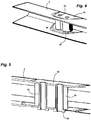
- the figures 1, 2, 3 , 4 and 5 have a rear axle cross member 2 formed in a sheet, arranged in the transverse direction of the vehicle, having a section perpendicular to its substantially constant length forming a "U" placed horizontally, the opening of which is turned towards the rear.
- Each end of the cross member 2 comprises an arm 4 forwards arranged in the longitudinal direction of the vehicle, having at its front end a joint 6 mounted on an elastic block, receiving a fixing screw on the body of the vehicle arranged in the direction transverse of the vehicle.
- Each end of the cross member comprises a vertical sheet 8 receiving the hub of a rear wheel, and towards the rear a little before this end, a substantially horizontal cup 10 receiving the base of a suspension spring.
- the deformable cross member 2 has a certain flexibility in torsion along its own longitudinal direction, in order to provide an anti-tilt function which applies a return force when the suspension travel differences on each side of the vehicle. This flexibility, depending on the thickness of the sheet of the cross member 2 and the shape of its section, is calculated to obtain a desired stiffness.
- the cross member 2 has on the left side, just before the fixing of the cup 10, two flats 12 each formed on a wing of its section, parallel to each other.
- the flats 12 stop towards the rear before the edge of the wings of the cross member 2, so as to leave a constant section at the level of this rear edge.
- a vertically elongated support 14 has a flat base resting on the upper flat 12 of the cross member 2, which is clamped by two screws 28 passing through this cross member, spaced apart in the transverse direction of the vehicle, and aligned in this direction.
- the upper end of the support 14 comprises a ring 16 having an axis arranged substantially in the longitudinal direction of the vehicle, receiving a fixing screw 18 of a yoke 20 formed at the end of a transverse guide bar 22.
- the other end of the guide bar 22 comprises a ring 24 having an axis arranged in the longitudinal direction, intended to be inserted in a yoke fixed under the body of the vehicle.
- the cross member 2 is guided transversely by the guide bar 22 resistant to transverse forces in bends, which can follow the movements of the suspension thanks to its mounting with end caps, while remaining close to the horizontal direction .
- the length of the guide bar 22 gives a very small variation in the transverse distance between its ends, which maintains the geometry of the rear axle.
- Each screw 28 for fixing the support 14 engaged from below is fitted in a tubular insert 32 which is itself fitted in a bore of each wing of the cross member 2, and between these wings in a bore of a spacer 30.
- the threaded upper end of each screw 28 is engaged in a threaded bore passing through a boss 26 disposed on each side of the support 14.
- the spacer 30 has two parallel flat surfaces fitted inside the flats 12 of the cross member 2, and an outline forming two lobes each centered on a screw 28, so as to reduce its mass.
- the spacer 30 maintains a spacing between the two flats 12 by having a high rigidity, allowing a significant tightening of the screws 28 passing through the cross member 2.
- Each insert 32 comprises a flange 34 coming below the lower flat 12, then a tubular part fitted in a bore of each flat, and in a bore of the spacer 30 with a small clearance to facilitate the introduction.
- the upper end of the insert 32 is crimped on the upper flat 12, by making this end open out in the thickness of the sheet around the drilling of this flat.
- the spacer 30 is easily introduced between the two flats 12, providing a small clearance.
- the two inserts 32 are introduced from below into the cross member 2, then the upper end of these inserts is crimped by performing a clamping. axial sheet of the cross member which eliminates this play.
- the fatigue strength of the screws 28 may be greater than that of a weld performed according to the prior art to fix the support 14 on the cross member 2, which ensures the resistance over time of this support.
- a sub-assembly formed by the cross member 2 having received the spacer 30 held by the two inserts 32 is thus produced beforehand, which can be easily handled without risking losing this spacer, which can subsequently receive the support 14 in a simple manner. by tightening the two screws 28.
- the sleeper system according to the invention makes it possible to adapt easily and economically to different deformable sleepers 2 having the same total height of its section, made with varied sheet thicknesses in order to adapt its torsional stiffness according to its direction. clean longitudinal.
- the same inserts 32 and the same screws 28 are kept, and the height of the spacer 30 is reduced as a function of the thickness of the sheets of the cross member 2 in order to adjust this spacer inside the cross member. .
- a modular system is thus obtained which uses the same manufacturing stations comprising a unique and robust manufacturing process, to perform the crimping of the inserts 32 and the screwing of the screws 28, with different sheet thicknesses of the sleepers 2.
Landscapes
- Engineering & Computer Science (AREA)
- Mechanical Engineering (AREA)
- Body Structure For Vehicles (AREA)
- Vehicle Body Suspensions (AREA)
Claims (10)
- Kraftfahrzeug-Hinterachssystem mit einem Querträger (2) aus Blech, der in einem Querschnitt senkrecht zu seiner Länge ein offenes "U" bildet, ausgestattet mit einem Träger (14), der an seinem Ende eine Befestigung (16) aufweist, die zur Aufnahme des Endes von eine Führungsstange (22) dieses Querträgers (2), die in der Querrichtung des Fahrzeugs angeordnet ist, die die Richtung senkrecht zur Fahrtrichtung dieses Fahrzeugs ist, dadurch gekennzeichnet, dass sie mindestens zwei Befestigungsklammern (28) mit Schrauben umfasst, die durch den Querträger (2) und einen Abstandhalter (30) hindurchführen, der zwischen den beiden Flügeln des "U"-Profils dieses Querträgers (2) angebracht ist, um die Stütze (14) auf dem Querträger (2) zu befestigen.
- Querträgersystem nach Anspruch 1, dadurch gekennzeichnet, dass der Querträger (2) zwei Abflachungen (12) aufweist, die jeweils an einem Flügel des " U "-Profils in Höhe des Abstandhalters (30) angeordnet sind.
- Querträgersystem nach Anspruch 2, dadurch gekennzeichnet, daß die beiden Abflachungen (12) parallel sind, die Abstandshalter (30) zwischen eingestellt werden, sind zwei Abflachungen (12).
- Querträgersystem nach einem der vorhergehenden Ansprüche, dadurch gekennzeichnet, daß sie zwei Befestigungsschrauben (28) ausgerichtet in der Querrichtung des Fahrzeugs, angeordnet sind und jeweils eine Seite des Trägers (14).
- Querträgersystem nach Anspruch 4, dadurch gekennzeichnet, daß der Träger (14) auf jeder Seite eine Nabe (26) aufweist, die eine Befestigungsschraube (28) aufnimmt, die diese Nabe durchdringt.
- Querträgersystem nach einem der vorhergehenden Ansprüche, dadurch gekennzeichnet, dass jede Schraube (28) in einen den Querträger (2) durchsetzenden rohrförmigen Einsatz (32) eingepasst ist.
- Querträgersystem nach Anspruch 6, dadurch gekennzeichnet, dass der rohrförmige Einsatz (32) zwischen den beiden Außenflächen des Querträgers (2) gequetscht ist, um eine Klemmung des Distanzstücks (30) zu bilden.
- Querträgersystem nach einem der vorhergehenden Ansprüche, dadurch gekennzeichnet, dass der Träger (14) eine längliche Form aufweist, die senkrecht zum Querträger (2) an der auf diesem Querträger (2) liegenden Fläche befestigt ist.
- Querträgersystem nach einem der vorhergehenden Ansprüche, dadurch gekennzeichnet, dass der Querträger (2) verformbar ist und in seiner Längsrichtung eine Torsionsflexibilität aufweist.
- Kraftfahrzeug, das mit einem Querträgersystem ausgestattet ist, das einen Hinterachsquerträger (2) und eine an diesem Querträger (2) durch einen Träger (14) befestigte Führungsstange (22) aufweist, dadurch gekennzeichnet, dass dieses Querträgersystem gemäß nach einem der vorhergehenden Ansprüche.
Applications Claiming Priority (2)
| Application Number | Priority Date | Filing Date | Title |
|---|---|---|---|
| FR1757713A FR3070141B1 (fr) | 2017-08-17 | 2017-08-17 | Systeme de traverse de vehicule automobile recevant une barre de guidage transversal |
| PCT/FR2018/051666 WO2019034813A1 (fr) | 2017-08-17 | 2018-07-04 | Systeme de traverse de vehicule automobile recevant une barre de guidage transversal |
Publications (2)
| Publication Number | Publication Date |
|---|---|
| EP3684635A1 EP3684635A1 (de) | 2020-07-29 |
| EP3684635B1 true EP3684635B1 (de) | 2021-10-20 |
Family
ID=60627754
Family Applications (1)
| Application Number | Title | Priority Date | Filing Date |
|---|---|---|---|
| EP18749463.8A Active EP3684635B1 (de) | 2017-08-17 | 2018-07-04 | Querträgersystem für ein kraftfahrzeug, das einen querführungsstab aufnimmt |
Country Status (5)
| Country | Link |
|---|---|
| EP (1) | EP3684635B1 (de) |
| CN (1) | CN110997366B (de) |
| FR (1) | FR3070141B1 (de) |
| MA (1) | MA50152A (de) |
| WO (1) | WO2019034813A1 (de) |
Families Citing this family (1)
| Publication number | Priority date | Publication date | Assignee | Title |
|---|---|---|---|---|
| US12330469B1 (en) * | 2024-09-16 | 2025-06-17 | Ford Global Technologies, Llc | Vehicle chassis system with an offset track bar |
Family Cites Families (15)
| Publication number | Priority date | Publication date | Assignee | Title |
|---|---|---|---|---|
| JPH06262920A (ja) * | 1993-03-15 | 1994-09-20 | Nissan Motor Co Ltd | リンク取付け構造 |
| JPH06286444A (ja) * | 1993-03-31 | 1994-10-11 | Nissan Shatai Co Ltd | ツイストアクスル式リアサスペンション |
| JPH08253010A (ja) * | 1995-03-16 | 1996-10-01 | Nissan Motor Co Ltd | リンク取付け構造 |
| US20040104547A1 (en) * | 2002-12-03 | 2004-06-03 | Mcfarland Richard L. | Pneumatic suspension system for vehicles |
| AU2003900336A0 (en) * | 2003-01-28 | 2003-02-13 | Steerable Wheel Systems Pty Ltd | Steerable single wheel unit for trailers |
| JP4276566B2 (ja) * | 2004-03-24 | 2009-06-10 | ダイハツ工業株式会社 | 車両用ラテラルロッドの支持構造 |
| FR2877109B1 (fr) | 2004-10-25 | 2007-01-19 | Somfy Sas | Procede de perfectionnement d'un ecran motorise et ecran motorise pour sa mise en oeuvre |
| FR2892974A1 (fr) * | 2005-11-10 | 2007-05-11 | Peugeot Citroen Automobiles Sa | Train arriere de vehicule automobile |
| FR2941996B1 (fr) | 2009-02-06 | 2014-05-09 | Soprofen | Systeme de projection pour volet coulissant |
| FR2942842B1 (fr) | 2009-03-06 | 2016-12-16 | Somfy Sas | Procede de reglage d'une installation de volet roulant a lames orientables motorise |
| US8616603B2 (en) * | 2010-04-23 | 2013-12-31 | The Raymond Corporation | Operator ride enhancement system |
| FR2962759B1 (fr) | 2010-07-13 | 2013-10-04 | Franciaflex | Volet roulant inclinable automatique |
| FR2983232B1 (fr) | 2011-11-24 | 2014-10-10 | Zurfluh Feller | Dispositif de manoeuvre de la projection d'un tablier de volet roulant, et volet roulant equipe d'un tel dispositif. |
| FR3003805B1 (fr) * | 2013-03-27 | 2015-03-27 | Peugeot Citroen Automobiles Sa | Palier de barre anti-devers de vehicule automobile, comprenant une bride avec un percage allonge |
| FR3009577B1 (fr) | 2013-08-06 | 2016-02-12 | Zurfluh Feller | Installation de volet roulant |
-
2017
- 2017-08-17 FR FR1757713A patent/FR3070141B1/fr not_active Expired - Fee Related
-
2018
- 2018-07-04 MA MA050152A patent/MA50152A/fr unknown
- 2018-07-04 EP EP18749463.8A patent/EP3684635B1/de active Active
- 2018-07-04 CN CN201880052864.4A patent/CN110997366B/zh active Active
- 2018-07-04 WO PCT/FR2018/051666 patent/WO2019034813A1/fr not_active Ceased
Also Published As
| Publication number | Publication date |
|---|---|
| MA50152A (fr) | 2020-07-29 |
| WO2019034813A1 (fr) | 2019-02-21 |
| FR3070141B1 (fr) | 2019-08-16 |
| EP3684635A1 (de) | 2020-07-29 |
| CN110997366A (zh) | 2020-04-10 |
| FR3070141A1 (fr) | 2019-02-22 |
| CN110997366B (zh) | 2023-04-28 |
Similar Documents
| Publication | Publication Date | Title |
|---|---|---|
| FR2960184A1 (fr) | Agencement d'essieu, de preference d'un essieu rigide pour vehicules automobiles | |
| EP1827880B1 (de) | Flexible achse mit einem querträger mit trapezförmigem querschnitt, entsprechender querträger, fahrzeug und herstellungsverfahren | |
| FR2936182A3 (fr) | Traverse en v a pointe verticale pourvue d'un palonnier et essieu et vehicule correspondant | |
| EP1904316B1 (de) | Flexible kraftfahrzeugachse mit einer querverstrebung mit offenem querschnitt, deren flanken geradlinige ränder enthalten, querverstrebung und entsprechendes fahrzeug | |
| EP3684635B1 (de) | Querträgersystem für ein kraftfahrzeug, das einen querführungsstab aufnimmt | |
| EP3668732B1 (de) | Kraftfahrzeugquerträgersystem mit einsätzen für eine querführungsstange | |
| EP2004429B1 (de) | Hinterachse eines fahrzeuges, im besonderen eines kraftfahrzeuges, sowie mit dieser hinterachse ausgestattetes fahrzeug | |
| EP3668733B1 (de) | Verfahren zur herstellung von querträgern für kraftfahrzeuge mit einer querführungsstange | |
| EP2189311B1 (de) | Hinterachse für Kraftfahrzeuge umfassend zwei Aufhängungsarme mit einer vertikalen Öffnung | |
| EP3386782B1 (de) | Hinterachse eines kraftfahrzeugs mit haltemitteln zur verbesserung der klebeverbindung eines verbundmaterialquerträgers mit den armen | |
| FR3003805A1 (fr) | Palier de barre anti-devers de vehicule automobile, comprenant une bride avec un percage allonge | |
| FR2994129A1 (fr) | Systeme de palier pour une barre anti-devers de vehicule automobile, comportant une entretoise | |
| WO2014154968A1 (fr) | Palier de fixation d'une barre anti-dévers au chasisis d'un véhicule automobile | |
| EP3317131B1 (de) | Aufhängungsvorrichtung für ein kraftfahrzeugrad mit einem lenker mit einem blechkörper und einem daran befestigten massiven kopf | |
| EP2170637B1 (de) | Hinterachse für ein automobil mit einer h-struktur mit einer querstrebe mit geschlossenem profil | |
| EP0943826B1 (de) | Verbindungsvorrichtung zwischen einer Stange und einer Bohrung des Antirollstabes eines Fahrzeuges | |
| FR3052394A1 (fr) | Traverse deformable a inserts de renfort d’extensions variables, pour un train arriere de vehicule | |
| WO2013117835A1 (fr) | Essieu souple arriere a palonnier | |
| FR3138896A1 (fr) | Train arrière de véhicule automobile fixé sur une doublure du longeronnet | |
| FR3123594A1 (fr) | Train arriere pour vehicule automobile du type a deux bras tires longitudinaux a comportement elastique ameliore |
Legal Events
| Date | Code | Title | Description |
|---|---|---|---|
| STAA | Information on the status of an ep patent application or granted ep patent |
Free format text: STATUS: UNKNOWN |
|
| STAA | Information on the status of an ep patent application or granted ep patent |
Free format text: STATUS: THE INTERNATIONAL PUBLICATION HAS BEEN MADE |
|
| PUAI | Public reference made under article 153(3) epc to a published international application that has entered the european phase |
Free format text: ORIGINAL CODE: 0009012 |
|
| STAA | Information on the status of an ep patent application or granted ep patent |
Free format text: STATUS: REQUEST FOR EXAMINATION WAS MADE |
|
| 17P | Request for examination filed |
Effective date: 20200115 |
|
| AK | Designated contracting states |
Kind code of ref document: A1 Designated state(s): AL AT BE BG CH CY CZ DE DK EE ES FI FR GB GR HR HU IE IS IT LI LT LU LV MC MK MT NL NO PL PT RO RS SE SI SK SM TR |
|
| AX | Request for extension of the european patent |
Extension state: BA ME |
|
| RAP1 | Party data changed (applicant data changed or rights of an application transferred) |
Owner name: PSA AUTOMOBILES SA |
|
| DAX | Request for extension of the european patent (deleted) | ||
| RAV | Requested validation state of the european patent: fee paid |
Extension state: MA Effective date: 20200115 |
|
| GRAP | Despatch of communication of intention to grant a patent |
Free format text: ORIGINAL CODE: EPIDOSNIGR1 |
|
| STAA | Information on the status of an ep patent application or granted ep patent |
Free format text: STATUS: GRANT OF PATENT IS INTENDED |
|
| INTG | Intention to grant announced |
Effective date: 20210624 |
|
| GRAS | Grant fee paid |
Free format text: ORIGINAL CODE: EPIDOSNIGR3 |
|
| GRAA | (expected) grant |
Free format text: ORIGINAL CODE: 0009210 |
|
| STAA | Information on the status of an ep patent application or granted ep patent |
Free format text: STATUS: THE PATENT HAS BEEN GRANTED |
|
| AK | Designated contracting states |
Kind code of ref document: B1 Designated state(s): AL AT BE BG CH CY CZ DE DK EE ES FI FR GB GR HR HU IE IS IT LI LT LU LV MC MK MT NL NO PL PT RO RS SE SI SK SM TR |
|
| REG | Reference to a national code |
Ref country code: GB Ref legal event code: FG4D Free format text: NOT ENGLISH |
|
| REG | Reference to a national code |
Ref country code: CH Ref legal event code: EP |
|
| REG | Reference to a national code |
Ref country code: DE Ref legal event code: R084 Ref document number: 602018025345 Country of ref document: DE |
|
| REG | Reference to a national code |
Ref country code: IE Ref legal event code: FG4D Free format text: LANGUAGE OF EP DOCUMENT: FRENCH |
|
| REG | Reference to a national code |
Ref country code: DE Ref legal event code: R096 Ref document number: 602018025345 Country of ref document: DE |
|
| REG | Reference to a national code |
Ref country code: AT Ref legal event code: REF Ref document number: 1439651 Country of ref document: AT Kind code of ref document: T Effective date: 20211115 |
|
| REG | Reference to a national code |
Ref country code: GB Ref legal event code: 746 Effective date: 20211123 |
|
| REG | Reference to a national code |
Ref country code: LT Ref legal event code: MG9D |
|
| REG | Reference to a national code |
Ref country code: NL Ref legal event code: MP Effective date: 20211020 |
|
| REG | Reference to a national code |
Ref country code: AT Ref legal event code: MK05 Ref document number: 1439651 Country of ref document: AT Kind code of ref document: T Effective date: 20211020 |
|
| PG25 | Lapsed in a contracting state [announced via postgrant information from national office to epo] |
Ref country code: RS Free format text: LAPSE BECAUSE OF FAILURE TO SUBMIT A TRANSLATION OF THE DESCRIPTION OR TO PAY THE FEE WITHIN THE PRESCRIBED TIME-LIMIT Effective date: 20211020 Ref country code: LT Free format text: LAPSE BECAUSE OF FAILURE TO SUBMIT A TRANSLATION OF THE DESCRIPTION OR TO PAY THE FEE WITHIN THE PRESCRIBED TIME-LIMIT Effective date: 20211020 Ref country code: FI Free format text: LAPSE BECAUSE OF FAILURE TO SUBMIT A TRANSLATION OF THE DESCRIPTION OR TO PAY THE FEE WITHIN THE PRESCRIBED TIME-LIMIT Effective date: 20211020 Ref country code: BG Free format text: LAPSE BECAUSE OF FAILURE TO SUBMIT A TRANSLATION OF THE DESCRIPTION OR TO PAY THE FEE WITHIN THE PRESCRIBED TIME-LIMIT Effective date: 20220120 Ref country code: AT Free format text: LAPSE BECAUSE OF FAILURE TO SUBMIT A TRANSLATION OF THE DESCRIPTION OR TO PAY THE FEE WITHIN THE PRESCRIBED TIME-LIMIT Effective date: 20211020 |
|
| PG25 | Lapsed in a contracting state [announced via postgrant information from national office to epo] |
Ref country code: IS Free format text: LAPSE BECAUSE OF FAILURE TO SUBMIT A TRANSLATION OF THE DESCRIPTION OR TO PAY THE FEE WITHIN THE PRESCRIBED TIME-LIMIT Effective date: 20220220 Ref country code: SE Free format text: LAPSE BECAUSE OF FAILURE TO SUBMIT A TRANSLATION OF THE DESCRIPTION OR TO PAY THE FEE WITHIN THE PRESCRIBED TIME-LIMIT Effective date: 20211020 Ref country code: PT Free format text: LAPSE BECAUSE OF FAILURE TO SUBMIT A TRANSLATION OF THE DESCRIPTION OR TO PAY THE FEE WITHIN THE PRESCRIBED TIME-LIMIT Effective date: 20220221 Ref country code: PL Free format text: LAPSE BECAUSE OF FAILURE TO SUBMIT A TRANSLATION OF THE DESCRIPTION OR TO PAY THE FEE WITHIN THE PRESCRIBED TIME-LIMIT Effective date: 20211020 Ref country code: NO Free format text: LAPSE BECAUSE OF FAILURE TO SUBMIT A TRANSLATION OF THE DESCRIPTION OR TO PAY THE FEE WITHIN THE PRESCRIBED TIME-LIMIT Effective date: 20220120 Ref country code: NL Free format text: LAPSE BECAUSE OF FAILURE TO SUBMIT A TRANSLATION OF THE DESCRIPTION OR TO PAY THE FEE WITHIN THE PRESCRIBED TIME-LIMIT Effective date: 20211020 Ref country code: LV Free format text: LAPSE BECAUSE OF FAILURE TO SUBMIT A TRANSLATION OF THE DESCRIPTION OR TO PAY THE FEE WITHIN THE PRESCRIBED TIME-LIMIT Effective date: 20211020 Ref country code: HR Free format text: LAPSE BECAUSE OF FAILURE TO SUBMIT A TRANSLATION OF THE DESCRIPTION OR TO PAY THE FEE WITHIN THE PRESCRIBED TIME-LIMIT Effective date: 20211020 Ref country code: GR Free format text: LAPSE BECAUSE OF FAILURE TO SUBMIT A TRANSLATION OF THE DESCRIPTION OR TO PAY THE FEE WITHIN THE PRESCRIBED TIME-LIMIT Effective date: 20220121 Ref country code: ES Free format text: LAPSE BECAUSE OF FAILURE TO SUBMIT A TRANSLATION OF THE DESCRIPTION OR TO PAY THE FEE WITHIN THE PRESCRIBED TIME-LIMIT Effective date: 20211020 |
|
| REG | Reference to a national code |
Ref country code: DE Ref legal event code: R097 Ref document number: 602018025345 Country of ref document: DE |
|
| PG25 | Lapsed in a contracting state [announced via postgrant information from national office to epo] |
Ref country code: SM Free format text: LAPSE BECAUSE OF FAILURE TO SUBMIT A TRANSLATION OF THE DESCRIPTION OR TO PAY THE FEE WITHIN THE PRESCRIBED TIME-LIMIT Effective date: 20211020 Ref country code: SK Free format text: LAPSE BECAUSE OF FAILURE TO SUBMIT A TRANSLATION OF THE DESCRIPTION OR TO PAY THE FEE WITHIN THE PRESCRIBED TIME-LIMIT Effective date: 20211020 Ref country code: RO Free format text: LAPSE BECAUSE OF FAILURE TO SUBMIT A TRANSLATION OF THE DESCRIPTION OR TO PAY THE FEE WITHIN THE PRESCRIBED TIME-LIMIT Effective date: 20211020 Ref country code: EE Free format text: LAPSE BECAUSE OF FAILURE TO SUBMIT A TRANSLATION OF THE DESCRIPTION OR TO PAY THE FEE WITHIN THE PRESCRIBED TIME-LIMIT Effective date: 20211020 Ref country code: DK Free format text: LAPSE BECAUSE OF FAILURE TO SUBMIT A TRANSLATION OF THE DESCRIPTION OR TO PAY THE FEE WITHIN THE PRESCRIBED TIME-LIMIT Effective date: 20211020 Ref country code: CZ Free format text: LAPSE BECAUSE OF FAILURE TO SUBMIT A TRANSLATION OF THE DESCRIPTION OR TO PAY THE FEE WITHIN THE PRESCRIBED TIME-LIMIT Effective date: 20211020 |
|
| PLBE | No opposition filed within time limit |
Free format text: ORIGINAL CODE: 0009261 |
|
| STAA | Information on the status of an ep patent application or granted ep patent |
Free format text: STATUS: NO OPPOSITION FILED WITHIN TIME LIMIT |
|
| 26N | No opposition filed |
Effective date: 20220721 |
|
| PG25 | Lapsed in a contracting state [announced via postgrant information from national office to epo] |
Ref country code: AL Free format text: LAPSE BECAUSE OF FAILURE TO SUBMIT A TRANSLATION OF THE DESCRIPTION OR TO PAY THE FEE WITHIN THE PRESCRIBED TIME-LIMIT Effective date: 20211020 |
|
| PG25 | Lapsed in a contracting state [announced via postgrant information from national office to epo] |
Ref country code: SI Free format text: LAPSE BECAUSE OF FAILURE TO SUBMIT A TRANSLATION OF THE DESCRIPTION OR TO PAY THE FEE WITHIN THE PRESCRIBED TIME-LIMIT Effective date: 20211020 |
|
| PG25 | Lapsed in a contracting state [announced via postgrant information from national office to epo] |
Ref country code: MC Free format text: LAPSE BECAUSE OF FAILURE TO SUBMIT A TRANSLATION OF THE DESCRIPTION OR TO PAY THE FEE WITHIN THE PRESCRIBED TIME-LIMIT Effective date: 20211020 |
|
| REG | Reference to a national code |
Ref country code: CH Ref legal event code: PL |
|
| REG | Reference to a national code |
Ref country code: BE Ref legal event code: MM Effective date: 20220731 |
|
| PG25 | Lapsed in a contracting state [announced via postgrant information from national office to epo] |
Ref country code: LU Free format text: LAPSE BECAUSE OF NON-PAYMENT OF DUE FEES Effective date: 20220704 Ref country code: LI Free format text: LAPSE BECAUSE OF NON-PAYMENT OF DUE FEES Effective date: 20220731 Ref country code: CH Free format text: LAPSE BECAUSE OF NON-PAYMENT OF DUE FEES Effective date: 20220731 |
|
| PG25 | Lapsed in a contracting state [announced via postgrant information from national office to epo] |
Ref country code: IT Free format text: LAPSE BECAUSE OF FAILURE TO SUBMIT A TRANSLATION OF THE DESCRIPTION OR TO PAY THE FEE WITHIN THE PRESCRIBED TIME-LIMIT Effective date: 20211020 Ref country code: BE Free format text: LAPSE BECAUSE OF NON-PAYMENT OF DUE FEES Effective date: 20220731 |
|
| PG25 | Lapsed in a contracting state [announced via postgrant information from national office to epo] |
Ref country code: IE Free format text: LAPSE BECAUSE OF NON-PAYMENT OF DUE FEES Effective date: 20220704 |
|
| REG | Reference to a national code |
Ref country code: DE Ref legal event code: R081 Ref document number: 602018025345 Country of ref document: DE Owner name: STELLANTIS AUTO SAS, FR Free format text: FORMER OWNER: PSA AUTOMOBILES SA, POISSY, FR |
|
| PG25 | Lapsed in a contracting state [announced via postgrant information from national office to epo] |
Ref country code: MK Free format text: LAPSE BECAUSE OF FAILURE TO SUBMIT A TRANSLATION OF THE DESCRIPTION OR TO PAY THE FEE WITHIN THE PRESCRIBED TIME-LIMIT Effective date: 20211020 Ref country code: CY Free format text: LAPSE BECAUSE OF FAILURE TO SUBMIT A TRANSLATION OF THE DESCRIPTION OR TO PAY THE FEE WITHIN THE PRESCRIBED TIME-LIMIT Effective date: 20211020 |
|
| VS25 | Lapsed in a validation state [announced via postgrant information from nat. office to epo] |
Ref country code: MA Free format text: LAPSE BECAUSE OF FAILURE TO SUBMIT A TRANSLATION OF THE DESCRIPTION OR TO PAY THE FEE WITHIN THE PRESCRIBED TIME-LIMIT Effective date: 20211020 |
|
| PG25 | Lapsed in a contracting state [announced via postgrant information from national office to epo] |
Ref country code: HU Free format text: LAPSE BECAUSE OF FAILURE TO SUBMIT A TRANSLATION OF THE DESCRIPTION OR TO PAY THE FEE WITHIN THE PRESCRIBED TIME-LIMIT; INVALID AB INITIO Effective date: 20180704 |
|
| PG25 | Lapsed in a contracting state [announced via postgrant information from national office to epo] |
Ref country code: MT Free format text: LAPSE BECAUSE OF FAILURE TO SUBMIT A TRANSLATION OF THE DESCRIPTION OR TO PAY THE FEE WITHIN THE PRESCRIBED TIME-LIMIT Effective date: 20211020 |
|
| PGFP | Annual fee paid to national office [announced via postgrant information from national office to epo] |
Ref country code: GB Payment date: 20250619 Year of fee payment: 8 |
|
| PGFP | Annual fee paid to national office [announced via postgrant information from national office to epo] |
Ref country code: FR Payment date: 20250620 Year of fee payment: 8 |
|
| PGFP | Annual fee paid to national office [announced via postgrant information from national office to epo] |
Ref country code: DE Payment date: 20250620 Year of fee payment: 8 |
|
| PG25 | Lapsed in a contracting state [announced via postgrant information from national office to epo] |
Ref country code: TR Free format text: LAPSE BECAUSE OF FAILURE TO SUBMIT A TRANSLATION OF THE DESCRIPTION OR TO PAY THE FEE WITHIN THE PRESCRIBED TIME-LIMIT Effective date: 20211020 |