EP3684635B1 - Cross-member system for a motor vehicle receiving a transverse guide bar - Google Patents
Cross-member system for a motor vehicle receiving a transverse guide bar Download PDFInfo
- Publication number
- EP3684635B1 EP3684635B1 EP18749463.8A EP18749463A EP3684635B1 EP 3684635 B1 EP3684635 B1 EP 3684635B1 EP 18749463 A EP18749463 A EP 18749463A EP 3684635 B1 EP3684635 B1 EP 3684635B1
- Authority
- EP
- European Patent Office
- Prior art keywords
- cross member
- support
- spacer
- vehicle
- guide bar
- Prior art date
- Legal status (The legal status is an assumption and is not a legal conclusion. Google has not performed a legal analysis and makes no representation as to the accuracy of the status listed.)
- Active
Links
Images

Classifications
-
- B—PERFORMING OPERATIONS; TRANSPORTING
- B60—VEHICLES IN GENERAL
- B60G—VEHICLE SUSPENSION ARRANGEMENTS
- B60G21/00—Interconnection systems for two or more resiliently-suspended wheels, e.g. for stabilising a vehicle body with respect to acceleration, deceleration or centrifugal forces
- B60G21/02—Interconnection systems for two or more resiliently-suspended wheels, e.g. for stabilising a vehicle body with respect to acceleration, deceleration or centrifugal forces permanently interconnected
- B60G21/04—Interconnection systems for two or more resiliently-suspended wheels, e.g. for stabilising a vehicle body with respect to acceleration, deceleration or centrifugal forces permanently interconnected mechanically
- B60G21/05—Interconnection systems for two or more resiliently-suspended wheels, e.g. for stabilising a vehicle body with respect to acceleration, deceleration or centrifugal forces permanently interconnected mechanically between wheels on the same axle but on different sides of the vehicle, i.e. the left and right wheel suspensions being interconnected
- B60G21/051—Trailing arm twist beam axles
-
- B—PERFORMING OPERATIONS; TRANSPORTING
- B60—VEHICLES IN GENERAL
- B60G—VEHICLE SUSPENSION ARRANGEMENTS
- B60G2200/00—Indexing codes relating to suspension types
- B60G2200/20—Semi-rigid axle suspensions
-
- B—PERFORMING OPERATIONS; TRANSPORTING
- B60—VEHICLES IN GENERAL
- B60G—VEHICLE SUSPENSION ARRANGEMENTS
- B60G2200/00—Indexing codes relating to suspension types
- B60G2200/30—Rigid axle suspensions
- B60G2200/34—Stabilising mechanisms, e.g. for lateral stability
- B60G2200/341—Panhard rod
-
- B—PERFORMING OPERATIONS; TRANSPORTING
- B60—VEHICLES IN GENERAL
- B60G—VEHICLE SUSPENSION ARRANGEMENTS
- B60G2206/00—Indexing codes related to the manufacturing of suspensions: constructional features, the materials used, procedures or tools
- B60G2206/01—Constructional features of suspension elements, e.g. arms, dampers, springs
- B60G2206/20—Constructional features of semi-rigid axles, e.g. twist beam type axles
-
- B—PERFORMING OPERATIONS; TRANSPORTING
- B60—VEHICLES IN GENERAL
- B60G—VEHICLE SUSPENSION ARRANGEMENTS
- B60G2206/00—Indexing codes related to the manufacturing of suspensions: constructional features, the materials used, procedures or tools
- B60G2206/01—Constructional features of suspension elements, e.g. arms, dampers, springs
- B60G2206/80—Manufacturing procedures
- B60G2206/82—Joining
- B60G2206/8207—Joining by screwing
Definitions
- the present invention relates to a cross member system for a rear axle of a motor vehicle, equipped with a transverse guide bar support for this cross member, as well as a motor vehicle comprising such a cross member system.
- a known type of vehicle rear axle presented in particular by the document FR-A1-2892974 , comprises a crosspiece guided laterally by a transverse bar, also called a “Panhard” bar, which is arranged substantially horizontally.
- the guide bar fixed by pivots on one side to the vehicle body and on the other to one end of the cross member, by passing through the vehicle, guides this cross member in the transverse direction of the vehicle during the deflections of the cross member. suspension, by taking up lateral forces, in particular when cornering.
- the guide bar must be arranged substantially horizontally so as to remain close to the horizontal direction when the suspension moves.
- the end of the guide bar fixed to the cross member then exhibits a substantially vertical movement, with an almost zero horizontal component, which ensures good guidance of this cross member.
- cross member for reasons of space, another type of known cross member, presented in particular by the document JP-B2-4276566 , comprises a cross member comprising at one end a support formed from sheet metal, extending towards the rear, which is welded to the rear face of this cross member. The end of the support receives the pivot of the transverse guide bar, which is thus slightly offset from the cross member.
- the support made of sheet metal and welded to the cross member also made of sheet metal can pose problems of resistance, in particular at the level of the welding between the support and the cross member, in order to resist the lateral forces transmitted by the guide bar which can be significant.
- a relatively long support constitutes a lever arm multiplying the transverse force coming from the guide bar, by forming an alternating force torque in the direction of the bends, which is applied to the connection between the support and the cross member.
- the fatigue strength of the weld beads may be insufficient, in particular for welds on a deformable cross member made of sheet metal.
- the object of the present invention is in particular to avoid these drawbacks of the prior art.
- a motor vehicle rear axle cross member system comprising a sheet metal cross member forming in a section perpendicular to its length an open "U", equipped with a support having at its end a fixing intended to receive the. end of a guide bar of this cross member arranged in the transverse direction of the vehicle which is the direction perpendicular to the direction of travel of this vehicle, this system being remarkable in that it comprises at least two fixing screws which pass through the cross member and a spacer fitted between the two wings of the "U" section of this cross member, to secure the support to the cross member.
- the sleeper system according to the invention may further include one or more of the following features, which may be combined with one another.
- the cross has two flats each arranged on a wing of the "U" section, at the level of the spacer.
- the two flats are parallel, the spacer being fitted between these two flats.
- Parallel reference faces are thus formed, facilitating the production and installation of the spacer, and giving great stability to the support fixed above.
- the cross member system comprises two fixing screws aligned in the transverse direction of the vehicle, and each arranged on one side of the support.
- the support may comprise on each side a boss receiving a fixing screw which passes through this boss.
- each screw is fitted in a tubular insert passing through the cross member.
- the tubular insert is crimped between the two outer faces of the cross member, so as to form a clamping of the spacer.
- the support comprises an elongated shape fixed perpendicularly to the cross member, on the face located on top of this cross member.
- the crossmember can be deformable, exhibiting torsional flexibility along the direction of its length.
- the subject of the invention is also a motor vehicle equipped with a cross member system comprising a rear axle cross member, and a guide bar fixed to this cross member by a support, remarkable in that this cross member system comprises the any of the preceding characteristics.
- the longitudinal direction of the vehicle is defined as being the direction of the direction of travel of this vehicle, along its length, and the transverse direction as the direction perpendicular to this longitudinal direction which is in a horizontal plane.
- the figures 1, 2, 3 , 4 and 5 have a rear axle cross member 2 formed in a sheet, arranged in the transverse direction of the vehicle, having a section perpendicular to its substantially constant length forming a "U" placed horizontally, the opening of which is turned towards the rear.
- Each end of the cross member 2 comprises an arm 4 forwards arranged in the longitudinal direction of the vehicle, having at its front end a joint 6 mounted on an elastic block, receiving a fixing screw on the body of the vehicle arranged in the direction transverse of the vehicle.
- Each end of the cross member comprises a vertical sheet 8 receiving the hub of a rear wheel, and towards the rear a little before this end, a substantially horizontal cup 10 receiving the base of a suspension spring.
- the deformable cross member 2 has a certain flexibility in torsion along its own longitudinal direction, in order to provide an anti-tilt function which applies a return force when the suspension travel differences on each side of the vehicle. This flexibility, depending on the thickness of the sheet of the cross member 2 and the shape of its section, is calculated to obtain a desired stiffness.
- the cross member 2 has on the left side, just before the fixing of the cup 10, two flats 12 each formed on a wing of its section, parallel to each other.
- the flats 12 stop towards the rear before the edge of the wings of the cross member 2, so as to leave a constant section at the level of this rear edge.
- a vertically elongated support 14 has a flat base resting on the upper flat 12 of the cross member 2, which is clamped by two screws 28 passing through this cross member, spaced apart in the transverse direction of the vehicle, and aligned in this direction.
- the upper end of the support 14 comprises a ring 16 having an axis arranged substantially in the longitudinal direction of the vehicle, receiving a fixing screw 18 of a yoke 20 formed at the end of a transverse guide bar 22.
- the other end of the guide bar 22 comprises a ring 24 having an axis arranged in the longitudinal direction, intended to be inserted in a yoke fixed under the body of the vehicle.
- the cross member 2 is guided transversely by the guide bar 22 resistant to transverse forces in bends, which can follow the movements of the suspension thanks to its mounting with end caps, while remaining close to the horizontal direction .
- the length of the guide bar 22 gives a very small variation in the transverse distance between its ends, which maintains the geometry of the rear axle.
- Each screw 28 for fixing the support 14 engaged from below is fitted in a tubular insert 32 which is itself fitted in a bore of each wing of the cross member 2, and between these wings in a bore of a spacer 30.
- the threaded upper end of each screw 28 is engaged in a threaded bore passing through a boss 26 disposed on each side of the support 14.
- the spacer 30 has two parallel flat surfaces fitted inside the flats 12 of the cross member 2, and an outline forming two lobes each centered on a screw 28, so as to reduce its mass.
- the spacer 30 maintains a spacing between the two flats 12 by having a high rigidity, allowing a significant tightening of the screws 28 passing through the cross member 2.
- Each insert 32 comprises a flange 34 coming below the lower flat 12, then a tubular part fitted in a bore of each flat, and in a bore of the spacer 30 with a small clearance to facilitate the introduction.
- the upper end of the insert 32 is crimped on the upper flat 12, by making this end open out in the thickness of the sheet around the drilling of this flat.
- the spacer 30 is easily introduced between the two flats 12, providing a small clearance.
- the two inserts 32 are introduced from below into the cross member 2, then the upper end of these inserts is crimped by performing a clamping. axial sheet of the cross member which eliminates this play.
- the fatigue strength of the screws 28 may be greater than that of a weld performed according to the prior art to fix the support 14 on the cross member 2, which ensures the resistance over time of this support.
- a sub-assembly formed by the cross member 2 having received the spacer 30 held by the two inserts 32 is thus produced beforehand, which can be easily handled without risking losing this spacer, which can subsequently receive the support 14 in a simple manner. by tightening the two screws 28.
- the sleeper system according to the invention makes it possible to adapt easily and economically to different deformable sleepers 2 having the same total height of its section, made with varied sheet thicknesses in order to adapt its torsional stiffness according to its direction. clean longitudinal.
- the same inserts 32 and the same screws 28 are kept, and the height of the spacer 30 is reduced as a function of the thickness of the sheets of the cross member 2 in order to adjust this spacer inside the cross member. .
- a modular system is thus obtained which uses the same manufacturing stations comprising a unique and robust manufacturing process, to perform the crimping of the inserts 32 and the screwing of the screws 28, with different sheet thicknesses of the sleepers 2.
Landscapes
- Engineering & Computer Science (AREA)
- Mechanical Engineering (AREA)
- Body Structure For Vehicles (AREA)
- Vehicle Body Suspensions (AREA)
Description
La présente invention concerne un système de traverse pour un train arrière de véhicule automobile, équipé d'un support de barre de guidage transversal de cette traverse, ainsi qu'un véhicule automobile comportant un tel système de traverse.The present invention relates to a cross member system for a rear axle of a motor vehicle, equipped with a transverse guide bar support for this cross member, as well as a motor vehicle comprising such a cross member system.
Un type de train arrière de véhicule connu, présenté notamment par le document
La barre de guidage fixée par des pivots d'un côté à la caisse du véhicule et de l'autre à une extrémité de la traverse, réalise en traversant le véhicule un guidage de cette traverse dans la direction transversale du véhicule lors des débattements de la suspension, en reprenant les efforts latéraux en particulier dans les virages.The guide bar fixed by pivots on one side to the vehicle body and on the other to one end of the cross member, by passing through the vehicle, guides this cross member in the transverse direction of the vehicle during the deflections of the cross member. suspension, by taking up lateral forces, in particular when cornering.
La barre de guidage doit être disposée sensiblement horizontalement de manière à rester proche de la direction horizontale lors des débattements de la suspension. L'extrémité de la barre de guidage fixée sur la traverse présente alors un mouvement sensiblement vertical, avec une composante horizontale quasiment nulle ce qui assure un bon guidage de cette traverse.The guide bar must be arranged substantially horizontally so as to remain close to the horizontal direction when the suspension moves. The end of the guide bar fixed to the cross member then exhibits a substantially vertical movement, with an almost zero horizontal component, which ensures good guidance of this cross member.
Pour des raisons d'encombrement, un autre type de traverse connu, présenté notamment par le document
Toutefois le support réalisé en tôle et soudé sur la traverse réalisée aussi en tôle, peut poser des problèmes de résistance, notamment au niveau de la soudure entre le support et la traverse, afin de résister aux efforts latéraux transmis par la barre de guidage qui peuvent être importants.However, the support made of sheet metal and welded to the cross member also made of sheet metal, can pose problems of resistance, in particular at the level of the welding between the support and the cross member, in order to resist the lateral forces transmitted by the guide bar which can be significant.
Les contraintes de volume disponible sous la caisse du véhicule, et la nécessité de disposer la barre de guidage proche de la direction horizontale, peuvent imposer une certaine longueur au support.The volume constraints available under the body of the vehicle, and the need to have the guide bar close to the horizontal direction, can impose a certain length on the support.
En particulier un support relativement long constitue un bras de levier multipliant la force transversale venant de la barre de guidage, en formant un couple d'effort alterné suivant les directions des virages, qui s'applique sur la liaison entre le support et la traverse. La tenue en fatigue des cordons de soudure peut être insuffisante, notamment pour des soudures sur une traverse déformable réalisée en tôle.In particular, a relatively long support constitutes a lever arm multiplying the transverse force coming from the guide bar, by forming an alternating force torque in the direction of the bends, which is applied to the connection between the support and the cross member. The fatigue strength of the weld beads may be insufficient, in particular for welds on a deformable cross member made of sheet metal.
Pour y remédier il est connu de renforcer la tôle de la traverse au niveau de la liaison avec le support, notamment en ajoutant des épaisseurs de tôle. Toutefois ce procédé augmente la masse du véhicule, et modifie la flexibilité en torsion de cette traverse suivant son axe longitudinal, qui a une grande importance pour les trains arrière à traverse déformable.To remedy this, it is known practice to reinforce the sheet of the cross member at the level of the connection with the support, in particular by adding sheet thicknesses. However, this method increases the mass of the vehicle, and modifies the torsional flexibility of this cross member along its longitudinal axis, which is of great importance for rear axles with deformable cross members.
La présente invention a notamment pour but d'éviter ces inconvénients de la technique antérieure.The object of the present invention is in particular to avoid these drawbacks of the prior art.
Elle propose à cet effet un système de traverse de train arrière de véhicule automobile comportant une traverse en tôle formant dans une section perpendiculaire à sa longueur un « U » ouvert, équipée d'un support présentant à son extrémité une fixation prévue pour recevoir l'extrémité d'une barre de guidage de cette traverse disposée dans la direction transversale du véhicule qui est la direction perpendiculaire au sens de marche de ce véhicule, ce système étant remarquable en ce qu'il comporte au moins deux vis de fixation qui traversent la traverse et une entretoise ajustée entre les deux ailes de la section en « U » de cette traverse, pour fixer le support sur la traverse.For this purpose, it proposes a motor vehicle rear axle cross member system comprising a sheet metal cross member forming in a section perpendicular to its length an open "U", equipped with a support having at its end a fixing intended to receive the. end of a guide bar of this cross member arranged in the transverse direction of the vehicle which is the direction perpendicular to the direction of travel of this vehicle, this system being remarkable in that it comprises at least two fixing screws which pass through the cross member and a spacer fitted between the two wings of the "U" section of this cross member, to secure the support to the cross member.
Un avantage de ce système de traverse est que les deux vis écartées dans la direction transversale du véhicule, qui peuvent être serrées fortement grâce à l'entretoise empêchant un écrasement de la traverse au niveau de ces vis, donnent une grande stabilité au support qui peut résister à des forces alternées importantes appliquées à son extrémité par la barre de guidage transversale.An advantage of this cross member system is that the two screws spaced apart in the transverse direction of the vehicle, which can be tightened strongly thanks to the spacer preventing crushing of the cross member at the level of these screws, give great stability to the support which can resist forces important alternates applied at its end by the transverse guide bar.
Le système de traverse selon l'invention peut comporter de plus une ou plusieurs des caractéristiques suivantes, qui peuvent être combinées entre elles.The sleeper system according to the invention may further include one or more of the following features, which may be combined with one another.
Avantageusement la traverse comporte deux méplats disposés chacun sur une aile de la section en « U », au niveau de l'entretoise.Advantageously, the cross has two flats each arranged on a wing of the "U" section, at the level of the spacer.
Dans ce cas, avantageusement les deux méplats sont parallèles, l'entretoise étant ajustée entre ces deux méplats. On forme ainsi des faces de référence parallèles facilitant la réalisation et la mise en place de l'entretoise, et donnant une grande stabilité au support fixé dessus.In this case, advantageously the two flats are parallel, the spacer being fitted between these two flats. Parallel reference faces are thus formed, facilitating the production and installation of the spacer, and giving great stability to the support fixed above.
Avantageusement, le système de traverse comporte deux vis de fixation alignées dans la direction transversale du véhicule, et disposées chacune d'un côté du support.Advantageously, the cross member system comprises two fixing screws aligned in the transverse direction of the vehicle, and each arranged on one side of the support.
Dans ce cas le support peut comporter de chaque côté un bossage recevant une vis de fixation qui traverse ce bossage.In this case, the support may comprise on each side a boss receiving a fixing screw which passes through this boss.
Avantageusement, chaque vis est ajustée dans un insert tubulaire traversant la traverse.Advantageously, each screw is fitted in a tubular insert passing through the cross member.
Avantageusement, l'insert tubulaire est serti entre les deux faces extérieures de la traverse, de manière à former un serrage de l'entretoise.Advantageously, the tubular insert is crimped between the two outer faces of the cross member, so as to form a clamping of the spacer.
Avantageusement, le support comporte une forme allongée fixée perpendiculairement à la traverse, sur la face se trouvant sur le dessus de cette traverse.Advantageously, the support comprises an elongated shape fixed perpendicularly to the cross member, on the face located on top of this cross member.
En particulier la traverse peut être déformable, en présentant une flexibilité en torsion suivant la direction de sa longueur.In particular, the crossmember can be deformable, exhibiting torsional flexibility along the direction of its length.
L'invention a aussi pour objet un véhicule automobile équipé d'un système de traverse comprenant une traverse de train arrière, et d'une barre de guidage fixée à cette traverse par un support, remarquable en ce que ce système de traverse comporte l'une quelconque des caractéristiques précédentes.The subject of the invention is also a motor vehicle equipped with a cross member system comprising a rear axle cross member, and a guide bar fixed to this cross member by a support, remarkable in that this cross member system comprises the any of the preceding characteristics.
L'invention sera mieux comprise et d'autres caractéristiques et avantages apparaîtront plus clairement à la lecture de la description ci-après donnée à titre d'exemple, en référence aux dessins annexés dans lesquels :
- la
figure 1 présente un système de traverse selon l'invention pour un train arrière à traverse déformable, qui est équipé d'une barre de guidage transversal ; - la
figure 2 est une vue de détail du support de cette barre transversale ; - la
figure 3 est une vue en coupe de ce support, suivant un plan de coupe passant par l'axe des vis de fixation du support ; et - les
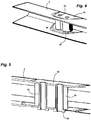
figures 4 et 5 sont des vues de détail de l'entretoise insérée dans la traverse sous le support, présentées respectivement en perspective et en coupe suivant un plan de coupe passant par l'axe des vis de fixation.
- the
figure 1 presents a cross member system according to the invention for a rear axle with a deformable cross member, which is equipped with a transverse guide bar; - the
figure 2 is a detail view of the support of this transverse bar; - the
figure 3 is a sectional view of this support, along a section plane passing through the axis of the support fixing screws; and - the
figures 4 and 5 are detail views of the spacer inserted into the cross member under the support, shown respectively in perspective and in section along a section plane passing through the axis of the fixing screws.
Dans la description qui suit la direction longitudinale du véhicule est définie comme étant la direction du sens de marche de ce véhicule, suivant sa longueur, et la direction transversale comme la direction perpendiculaire à cette direction longitudinale qui se trouve dans un plan horizontal.In the following description, the longitudinal direction of the vehicle is defined as being the direction of the direction of travel of this vehicle, along its length, and the transverse direction as the direction perpendicular to this longitudinal direction which is in a horizontal plane.
Les
Chaque extrémité de la traverse 2 comporte vers l'avant un bras 4 disposé dans la direction longitudinale du véhicule, présentant à son extrémité avant une articulation 6 montée sur un bloc élastique, recevant une vis de fixation sur la caisse du véhicule disposée dans la direction transversale du véhicule.Each end of the
Chaque extrémité de la traverse comporte une tôle verticale 8 recevant le moyeu d'une roue arrière, et vers l'arrière un peu avant cette extrémité, une coupelle sensiblement horizontale 10 recevant la base d'un ressort de suspension.Each end of the cross member comprises a vertical sheet 8 receiving the hub of a rear wheel, and towards the rear a little before this end, a substantially
La traverse 2 déformable présente une certaine flexibilité en torsion suivant sa direction longitudinale propre, afin d'assurer une fonction anti-dévers qui applique un effort de rappel lors des différences de débattement des suspensions de chaque côté du véhicule. Cette flexibilité dépendant de l'épaisseur de la tôle de la traverse 2 et de la forme de sa section, est calculée pour obtenir une raideur souhaitée.The
La traverse 2 présente du côté gauche, juste avant la fixation de la coupelle 10, deux méplats 12 formés chacun sur une aile de sa section, parallèles entre eux. Les méplats 12 s'arrêtent vers l'arrière avant le bord des ailes de la traverse 2, de façon à laisser une section constante au niveau de ce bord arrière.The
Un support 14 allongé verticalement, présente une base plane en appui sur le méplat supérieur 12 de la traverse 2, qui est serré par deux vis 28 traversant cette traverse, écartées dans la direction transversale du véhicule, et alignées suivant cette direction.A vertically
L'extrémité supérieure du support 14 comporte un anneau 16 présentant un axe disposé sensiblement dans la direction longitudinale du véhicule, recevant une vis de fixation 18 d'une chape 20 formée à l'extrémité d'une barre de guidage transversal 22. L'autre extrémité de la barre de guidage 22 comporte un anneau 24 présentant un axe disposé dans la direction longitudinale, prévu pour être inséré dans une chape fixée sous la caisse du véhicule.The upper end of the
De cette manière la traverse 2 est guidée transversalement par la barre de guidage 22 résistant aux efforts transversaux dans les virages, qui peut suivre les débattements de la suspension grâce à son montage avec des chapes d'extrémité, tout en restant proche de la direction horizontale.In this way the
La longueur de la barre de guidage 22 donne une très faible variation de la distance transversale entre ses extrémités, ce qui maintient la géométrie du train arrière.The length of the
Chaque vis 28 de fixation du support 14 engagée par le dessous, est ajustée dans un insert tubulaire 32 qui est lui-même ajusté dans un perçage de chaque aile de la traverse 2, et entre ces ailes dans un perçage d'une entretoise 30. L'extrémité supérieure filetée de chaque vis 28 est engagée dans un perçage taraudé traversant un bossage 26 disposé de chaque côté du support 14.Each
L'entretoise 30 comporte deux surfaces planes parallèles ajustées à l'intérieur des méplats 12 de la traverse 2, et un contour formant deux lobes centrés chacun sur une vis 28, de manière à réduire sa masse.The
L'entretoise 30 maintient un espacement entre les deux méplats 12 en présentant une rigidité élevée, permettant un serrage important des vis 28 traversant la traverse 2.The
Chaque insert 32 comporte une collerette 34 venant en dessous du méplat inférieur 12, puis une partie tubulaire ajustée dans un perçage de chaque méplat, et dans un perçage de l'entretoise 30 avec un petit jeu pour faciliter l'introduction. L'extrémité supérieure de l'insert 32 est sertie sur le méplat supérieur 12, en réalisant un épanouissement de cette extrémité dans l'épaisseur de la tôle autour du perçage de ce méplat.Each
De cette manière on introduit facilement l'entretoise 30 entre les deux méplats 12 en prévoyant un petit jeu. Ensuite on introduit les deux inserts 32 par le bas dans la traverse 2, puis on sertit l'extrémité supérieure de ces inserts en réalisant un serrage axial des tôles de la traverse ce qui supprime ce jeu.In this way, the
On obtient un serrage axial des deux méplats 12 et de l'entretoise 30, entre la collerette inférieure 34 et le sertissage supérieur, qui garantit le placage et le serrage de cet ensemble avant le montage des vis 28 du support 14. On réalise un sous-ensemble prêt au montage sur le véhicule.An axial clamping of the two
On notera que le serrage de l'ensemble des composants superposés, comprenant pour chaque vis 28 la collerette 34 de l'insert 32, les deux méplats 12 de la traverse 2 et les deux faces de l'entretoise 30, est important pour garantir le maintien du couple de serrage de ces vis dans le temps.It will be noted that the tightening of all the superimposed components, comprising for each
De plus après un dévissage des vis 28 en cas d'intervention en après-vente nécessitant un démontage du support 14, les méplats 12 de la traverse 2 restent serrés sur l'entretoise 30 ce qui facilite le remontage.In addition, after unscrewing the
L'écartement dans la direction transversale des deux vis 28 donne une grande stabilité latérale au support 14, dans la direction où il est soumis à des contraintes importantes venant de la barre de guidage 22.The spacing in the transverse direction of the two
La tenue des vis 28 en fatigue peut être supérieure à celle d'une soudure pratiquée suivant l'art antérieur pour fixer le support 14 sur la traverse 2, ce qui assure la tenue dans le temps de ce support.The fatigue strength of the
De plus l'effort de placage de la tôle des méplats 12 sur l'entretoise 30 étant donné par les inserts 32, cet effort n'est pas délivré par les vis 28 ce qui permet de les calculer au plus juste.In addition, the force of plating the plate of the
On réalise ainsi au préalable un sous-ensemble formé par la traverse 2 ayant reçu l'entretoise 30 maintenue par les deux inserts 32, pouvant être facilement manipulé sans risquer de perdre cette entretoise, qui peut recevoir par la suite de manière simple le support 14 par le serrage des deux vis 28.A sub-assembly formed by the
Le système de traverse selon l'invention permet de s'adapter facilement et de manière économique à différentes traverses déformables 2 présentant une même hauteur totale de sa section, réalisées avec des épaisseurs de tôle variées afin d'adapter sa raideur en torsion suivant sa direction longitudinale propre.The sleeper system according to the invention makes it possible to adapt easily and economically to different
Dans ce cas on conserve les mêmes inserts 32 et les mêmes vis 28, et on réduit la hauteur de l'entretoise 30 en fonction de l'épaisseur des tôles de la traverse 2 afin d'ajuster cette entretoise à l'intérieur de la traverse.In this case, the
On obtient ainsi un système modulaire qui utilise les mêmes postes de fabrication comportant un procédé de fabrication unique et robuste, pour réaliser le sertissage des inserts 32 et le vissage des vis 28, avec différentes épaisseurs de tôle des traverses 2.A modular system is thus obtained which uses the same manufacturing stations comprising a unique and robust manufacturing process, to perform the crimping of the
Claims (10)
- Motor vehicle rear axle cross member system comprising a sheet metal cross member (2) forming in a section perpendicular to its length an open "U", equipped with a support (14) having at its end a fixing (16) intended to receive the end of a guide bar (22) of this cross member (2) arranged in the transverse direction of the vehicle which is the direction perpendicular to the direction of travel of this vehicle, characterized in that it comprises at least two fixing screws (28) which pass through the cross member (2) and a spacer (30) fitted between the two wings of the "U" section of this cross member (2), to fix the support (14) on the cross member (2).
- Cross member system according to claim 1, characterized in that the cross member (2) comprises two flats (12) each arranged on a wing of the " U " section at the level of the spacer (30).
- Cross member system according to claim 2, characterized in that the two flats (12) are parallel, the spacer (30) being adjusted between are two flats (12).
- Cross member system according to any one of the preceding claims, characterized in that it comprises two fixing screws (28) aligned in the transverse direction of the vehicle, and each arranged one side of the support (14).
- Cross member system according to claim 4, characterized in that the support (14) comprises on each side a boss (26) receiving a fastening screw (28) passing through this boss.
- Cross member system according to any one of the preceding claims, characterized in that each screw (28) is fitted in a tubular insert (32) passing through the cross member (2).
- Cross member system according to claim 6, characterized in that the tubular insert (32) is crimped between the two outer faces of the cross member (2), so as to form a clamping of the spacer (30).
- Cross member system according to any one of the preceding claims, characterized in that the support (14) has an elongated form fastened perpendicularly to the cross member (2), on the a face located on the top of this cross (2).
- Cross member system according to any one of the preceding claims, characterized in that the cross member (2) is deformable, presenting a torsional flexibility following the direction of its length.
- Motor vehicle equipped with a cross member system comprising a cross member (2) of the rear axle, and a guide bar (22) fixed to this cross member (2) by a support (14), characterized in that this system cross member is according to any one of the preceding claims.
Applications Claiming Priority (2)
| Application Number | Priority Date | Filing Date | Title |
|---|---|---|---|
| FR1757713A FR3070141B1 (en) | 2017-08-17 | 2017-08-17 | MOTOR VEHICLE CROSSING SYSTEM RECEIVING A TRANSVERSE GUIDE BAR |
| PCT/FR2018/051666 WO2019034813A1 (en) | 2017-08-17 | 2018-07-04 | Cross-member system for a motor vehicle receiving a transverse guide bar |
Publications (2)
| Publication Number | Publication Date |
|---|---|
| EP3684635A1 EP3684635A1 (en) | 2020-07-29 |
| EP3684635B1 true EP3684635B1 (en) | 2021-10-20 |
Family
ID=60627754
Family Applications (1)
| Application Number | Title | Priority Date | Filing Date |
|---|---|---|---|
| EP18749463.8A Active EP3684635B1 (en) | 2017-08-17 | 2018-07-04 | Cross-member system for a motor vehicle receiving a transverse guide bar |
Country Status (5)
| Country | Link |
|---|---|
| EP (1) | EP3684635B1 (en) |
| CN (1) | CN110997366B (en) |
| FR (1) | FR3070141B1 (en) |
| MA (1) | MA50152A (en) |
| WO (1) | WO2019034813A1 (en) |
Families Citing this family (1)
| Publication number | Priority date | Publication date | Assignee | Title |
|---|---|---|---|---|
| US12330469B1 (en) * | 2024-09-16 | 2025-06-17 | Ford Global Technologies, Llc | Vehicle chassis system with an offset track bar |
Family Cites Families (15)
| Publication number | Priority date | Publication date | Assignee | Title |
|---|---|---|---|---|
| JPH06262920A (en) * | 1993-03-15 | 1994-09-20 | Nissan Motor Co Ltd | Link fitting structure |
| JPH06286444A (en) * | 1993-03-31 | 1994-10-11 | Nissan Shatai Co Ltd | Twist axle type suspension |
| JPH08253010A (en) * | 1995-03-16 | 1996-10-01 | Nissan Motor Co Ltd | Link mounting structure |
| US20040104547A1 (en) * | 2002-12-03 | 2004-06-03 | Mcfarland Richard L. | Pneumatic suspension system for vehicles |
| AU2003900336A0 (en) * | 2003-01-28 | 2003-02-13 | Steerable Wheel Systems Pty Ltd | Steerable single wheel unit for trailers |
| JP4276566B2 (en) * | 2004-03-24 | 2009-06-10 | ダイハツ工業株式会社 | Support structure for lateral rods for vehicles |
| FR2877109B1 (en) | 2004-10-25 | 2007-01-19 | Somfy Sas | METHOD FOR IMPROVING A MOTORIZED SCREEN AND MOTORIZED SCREEN FOR ITS IMPLEMENTATION |
| FR2892974A1 (en) * | 2005-11-10 | 2007-05-11 | Peugeot Citroen Automobiles Sa | Motor vehicle e.g. light lorry, rear train, has rear axle including axle head with plate and branch, and hinge pivot fixed to branch and coupled only on one side of stabilizer bar`s lower end whose another end remains free relative to axle |
| FR2941996B1 (en) | 2009-02-06 | 2014-05-09 | Soprofen | PROJECTION SYSTEM FOR SLIDING COMPONENTS |
| FR2942842B1 (en) | 2009-03-06 | 2016-12-16 | Somfy Sas | METHOD FOR ADJUSTING A MOTORIZED ROLLER SHUTTER INSTALLATION |
| US8616603B2 (en) * | 2010-04-23 | 2013-12-31 | The Raymond Corporation | Operator ride enhancement system |
| FR2962759B1 (en) | 2010-07-13 | 2013-10-04 | Franciaflex | AUTOMATIC TILTING SHUTTER |
| FR2983232B1 (en) | 2011-11-24 | 2014-10-10 | Zurfluh Feller | DEVICE FOR MANEUVERING THE PROJECTION OF A ROLLING SHUTTER APRON, AND ROLLING SHUTTER EQUIPPED WITH SUCH A DEVICE. |
| FR3003805B1 (en) * | 2013-03-27 | 2015-03-27 | Peugeot Citroen Automobiles Sa | MOTOR VEHICLE ANTI-DEVICE BAR BEARING, COMPRISING A FLANGE WITH AN EXTENDED DRILL |
| FR3009577B1 (en) | 2013-08-06 | 2016-02-12 | Zurfluh Feller | ROLLER SHUTTER INSTALLATION |
-
2017
- 2017-08-17 FR FR1757713A patent/FR3070141B1/en not_active Expired - Fee Related
-
2018
- 2018-07-04 EP EP18749463.8A patent/EP3684635B1/en active Active
- 2018-07-04 CN CN201880052864.4A patent/CN110997366B/en active Active
- 2018-07-04 MA MA050152A patent/MA50152A/en unknown
- 2018-07-04 WO PCT/FR2018/051666 patent/WO2019034813A1/en not_active Ceased
Also Published As
| Publication number | Publication date |
|---|---|
| MA50152A (en) | 2020-07-29 |
| CN110997366A (en) | 2020-04-10 |
| FR3070141A1 (en) | 2019-02-22 |
| EP3684635A1 (en) | 2020-07-29 |
| WO2019034813A1 (en) | 2019-02-21 |
| CN110997366B (en) | 2023-04-28 |
| FR3070141B1 (en) | 2019-08-16 |
Similar Documents
| Publication | Publication Date | Title |
|---|---|---|
| FR2960184A1 (en) | AXLE ARRANGEMENT, PREFERABLY OF A RIGID AXLE FOR MOTOR VEHICLES | |
| EP1827880B1 (en) | Flexible axle comprising a cross-member with trapezoid cross-section, corresponding cross-member, vehicle and manufacturing method | |
| FR2936182A3 (en) | V-RING WITH VERTICAL TIP PROVIDED WITH A PALLET AND AXLE AND CORRESPONDING VEHICLE | |
| EP1904316B1 (en) | Motor vehicle flexible axle, comprising a cross bracing with open cross-section whereof the flanks include rectilinear edges, cross bracing and corresponding motor vehicle | |
| EP3684635B1 (en) | Cross-member system for a motor vehicle receiving a transverse guide bar | |
| EP3668732B1 (en) | Motor vehicle cross member system having inserts for a transverse guide bar | |
| EP2004429B1 (en) | Rear axle of a vehicle, in particular a motor vehicle, and vehicle equipped with such a rear axle | |
| EP3668733B1 (en) | Method for manufacturing cross-members for motor vehicles with a transverse guide bar | |
| EP2189311B1 (en) | Rear axle for an automobile comprising two suspension arms with a vertical opening | |
| EP3386782B1 (en) | Rear axle of a motor vehicle comprising holding means for improving the adhesive bond of a composite material crossmember with the arms | |
| FR3003805A1 (en) | MOTOR VEHICLE ANTI-DEVICE BAR BEARING, COMPRISING A FLANGE WITH AN EXTENDED DRILL | |
| FR2994129A1 (en) | Bearing system for fastening anti-roll bar to body of motor vehicle, has spacer arranged inside arms, where spacer is adapted to be clamped between anti-roll bar and bearing when flange is fixed on body of vehicle | |
| WO2014154968A1 (en) | Bearing for fixing a stabiliser bar to the chassis of a motor vehicle | |
| EP3264940B1 (en) | Slide for slidable adjustment systems | |
| EP3317131B1 (en) | Suspension device for a motor vehicle wheel comprising an arm provided with a sheet-metal body and a solid head attached thereto | |
| EP2170637B1 (en) | Rear axle for automobile having an h structure with a closed profile crossbar | |
| EP0943826B1 (en) | Device for joining a link in a bore of an antiroll bar of a vehicle | |
| FR3052394A1 (en) | DEFORMABLE CROSSING WITH REINFORCING INSERTS OF VARIABLE EXTENSIONS, FOR A REAR VEHICLE TRAIN | |
| WO2013117835A1 (en) | Flexible rear axle having a yoke | |
| FR3138896A1 (en) | REAR END OF A MOTOR VEHICLE FIXED ON A LINING OF THE STRAP |
Legal Events
| Date | Code | Title | Description |
|---|---|---|---|
| STAA | Information on the status of an ep patent application or granted ep patent |
Free format text: STATUS: UNKNOWN |
|
| STAA | Information on the status of an ep patent application or granted ep patent |
Free format text: STATUS: THE INTERNATIONAL PUBLICATION HAS BEEN MADE |
|
| PUAI | Public reference made under article 153(3) epc to a published international application that has entered the european phase |
Free format text: ORIGINAL CODE: 0009012 |
|
| STAA | Information on the status of an ep patent application or granted ep patent |
Free format text: STATUS: REQUEST FOR EXAMINATION WAS MADE |
|
| 17P | Request for examination filed |
Effective date: 20200115 |
|
| AK | Designated contracting states |
Kind code of ref document: A1 Designated state(s): AL AT BE BG CH CY CZ DE DK EE ES FI FR GB GR HR HU IE IS IT LI LT LU LV MC MK MT NL NO PL PT RO RS SE SI SK SM TR |
|
| AX | Request for extension of the european patent |
Extension state: BA ME |
|
| RAP1 | Party data changed (applicant data changed or rights of an application transferred) |
Owner name: PSA AUTOMOBILES SA |
|
| DAX | Request for extension of the european patent (deleted) | ||
| RAV | Requested validation state of the european patent: fee paid |
Extension state: MA Effective date: 20200115 |
|
| GRAP | Despatch of communication of intention to grant a patent |
Free format text: ORIGINAL CODE: EPIDOSNIGR1 |
|
| STAA | Information on the status of an ep patent application or granted ep patent |
Free format text: STATUS: GRANT OF PATENT IS INTENDED |
|
| INTG | Intention to grant announced |
Effective date: 20210624 |
|
| GRAS | Grant fee paid |
Free format text: ORIGINAL CODE: EPIDOSNIGR3 |
|
| GRAA | (expected) grant |
Free format text: ORIGINAL CODE: 0009210 |
|
| STAA | Information on the status of an ep patent application or granted ep patent |
Free format text: STATUS: THE PATENT HAS BEEN GRANTED |
|
| AK | Designated contracting states |
Kind code of ref document: B1 Designated state(s): AL AT BE BG CH CY CZ DE DK EE ES FI FR GB GR HR HU IE IS IT LI LT LU LV MC MK MT NL NO PL PT RO RS SE SI SK SM TR |
|
| REG | Reference to a national code |
Ref country code: GB Ref legal event code: FG4D Free format text: NOT ENGLISH |
|
| REG | Reference to a national code |
Ref country code: CH Ref legal event code: EP |
|
| REG | Reference to a national code |
Ref country code: DE Ref legal event code: R084 Ref document number: 602018025345 Country of ref document: DE |
|
| REG | Reference to a national code |
Ref country code: IE Ref legal event code: FG4D Free format text: LANGUAGE OF EP DOCUMENT: FRENCH |
|
| REG | Reference to a national code |
Ref country code: DE Ref legal event code: R096 Ref document number: 602018025345 Country of ref document: DE |
|
| REG | Reference to a national code |
Ref country code: AT Ref legal event code: REF Ref document number: 1439651 Country of ref document: AT Kind code of ref document: T Effective date: 20211115 |
|
| REG | Reference to a national code |
Ref country code: GB Ref legal event code: 746 Effective date: 20211123 |
|
| REG | Reference to a national code |
Ref country code: LT Ref legal event code: MG9D |
|
| REG | Reference to a national code |
Ref country code: NL Ref legal event code: MP Effective date: 20211020 |
|
| REG | Reference to a national code |
Ref country code: AT Ref legal event code: MK05 Ref document number: 1439651 Country of ref document: AT Kind code of ref document: T Effective date: 20211020 |
|
| PG25 | Lapsed in a contracting state [announced via postgrant information from national office to epo] |
Ref country code: RS Free format text: LAPSE BECAUSE OF FAILURE TO SUBMIT A TRANSLATION OF THE DESCRIPTION OR TO PAY THE FEE WITHIN THE PRESCRIBED TIME-LIMIT Effective date: 20211020 Ref country code: LT Free format text: LAPSE BECAUSE OF FAILURE TO SUBMIT A TRANSLATION OF THE DESCRIPTION OR TO PAY THE FEE WITHIN THE PRESCRIBED TIME-LIMIT Effective date: 20211020 Ref country code: FI Free format text: LAPSE BECAUSE OF FAILURE TO SUBMIT A TRANSLATION OF THE DESCRIPTION OR TO PAY THE FEE WITHIN THE PRESCRIBED TIME-LIMIT Effective date: 20211020 Ref country code: BG Free format text: LAPSE BECAUSE OF FAILURE TO SUBMIT A TRANSLATION OF THE DESCRIPTION OR TO PAY THE FEE WITHIN THE PRESCRIBED TIME-LIMIT Effective date: 20220120 Ref country code: AT Free format text: LAPSE BECAUSE OF FAILURE TO SUBMIT A TRANSLATION OF THE DESCRIPTION OR TO PAY THE FEE WITHIN THE PRESCRIBED TIME-LIMIT Effective date: 20211020 |
|
| PG25 | Lapsed in a contracting state [announced via postgrant information from national office to epo] |
Ref country code: IS Free format text: LAPSE BECAUSE OF FAILURE TO SUBMIT A TRANSLATION OF THE DESCRIPTION OR TO PAY THE FEE WITHIN THE PRESCRIBED TIME-LIMIT Effective date: 20220220 Ref country code: SE Free format text: LAPSE BECAUSE OF FAILURE TO SUBMIT A TRANSLATION OF THE DESCRIPTION OR TO PAY THE FEE WITHIN THE PRESCRIBED TIME-LIMIT Effective date: 20211020 Ref country code: PT Free format text: LAPSE BECAUSE OF FAILURE TO SUBMIT A TRANSLATION OF THE DESCRIPTION OR TO PAY THE FEE WITHIN THE PRESCRIBED TIME-LIMIT Effective date: 20220221 Ref country code: PL Free format text: LAPSE BECAUSE OF FAILURE TO SUBMIT A TRANSLATION OF THE DESCRIPTION OR TO PAY THE FEE WITHIN THE PRESCRIBED TIME-LIMIT Effective date: 20211020 Ref country code: NO Free format text: LAPSE BECAUSE OF FAILURE TO SUBMIT A TRANSLATION OF THE DESCRIPTION OR TO PAY THE FEE WITHIN THE PRESCRIBED TIME-LIMIT Effective date: 20220120 Ref country code: NL Free format text: LAPSE BECAUSE OF FAILURE TO SUBMIT A TRANSLATION OF THE DESCRIPTION OR TO PAY THE FEE WITHIN THE PRESCRIBED TIME-LIMIT Effective date: 20211020 Ref country code: LV Free format text: LAPSE BECAUSE OF FAILURE TO SUBMIT A TRANSLATION OF THE DESCRIPTION OR TO PAY THE FEE WITHIN THE PRESCRIBED TIME-LIMIT Effective date: 20211020 Ref country code: HR Free format text: LAPSE BECAUSE OF FAILURE TO SUBMIT A TRANSLATION OF THE DESCRIPTION OR TO PAY THE FEE WITHIN THE PRESCRIBED TIME-LIMIT Effective date: 20211020 Ref country code: GR Free format text: LAPSE BECAUSE OF FAILURE TO SUBMIT A TRANSLATION OF THE DESCRIPTION OR TO PAY THE FEE WITHIN THE PRESCRIBED TIME-LIMIT Effective date: 20220121 Ref country code: ES Free format text: LAPSE BECAUSE OF FAILURE TO SUBMIT A TRANSLATION OF THE DESCRIPTION OR TO PAY THE FEE WITHIN THE PRESCRIBED TIME-LIMIT Effective date: 20211020 |
|
| REG | Reference to a national code |
Ref country code: DE Ref legal event code: R097 Ref document number: 602018025345 Country of ref document: DE |
|
| PG25 | Lapsed in a contracting state [announced via postgrant information from national office to epo] |
Ref country code: SM Free format text: LAPSE BECAUSE OF FAILURE TO SUBMIT A TRANSLATION OF THE DESCRIPTION OR TO PAY THE FEE WITHIN THE PRESCRIBED TIME-LIMIT Effective date: 20211020 Ref country code: SK Free format text: LAPSE BECAUSE OF FAILURE TO SUBMIT A TRANSLATION OF THE DESCRIPTION OR TO PAY THE FEE WITHIN THE PRESCRIBED TIME-LIMIT Effective date: 20211020 Ref country code: RO Free format text: LAPSE BECAUSE OF FAILURE TO SUBMIT A TRANSLATION OF THE DESCRIPTION OR TO PAY THE FEE WITHIN THE PRESCRIBED TIME-LIMIT Effective date: 20211020 Ref country code: EE Free format text: LAPSE BECAUSE OF FAILURE TO SUBMIT A TRANSLATION OF THE DESCRIPTION OR TO PAY THE FEE WITHIN THE PRESCRIBED TIME-LIMIT Effective date: 20211020 Ref country code: DK Free format text: LAPSE BECAUSE OF FAILURE TO SUBMIT A TRANSLATION OF THE DESCRIPTION OR TO PAY THE FEE WITHIN THE PRESCRIBED TIME-LIMIT Effective date: 20211020 Ref country code: CZ Free format text: LAPSE BECAUSE OF FAILURE TO SUBMIT A TRANSLATION OF THE DESCRIPTION OR TO PAY THE FEE WITHIN THE PRESCRIBED TIME-LIMIT Effective date: 20211020 |
|
| PLBE | No opposition filed within time limit |
Free format text: ORIGINAL CODE: 0009261 |
|
| STAA | Information on the status of an ep patent application or granted ep patent |
Free format text: STATUS: NO OPPOSITION FILED WITHIN TIME LIMIT |
|
| 26N | No opposition filed |
Effective date: 20220721 |
|
| PG25 | Lapsed in a contracting state [announced via postgrant information from national office to epo] |
Ref country code: AL Free format text: LAPSE BECAUSE OF FAILURE TO SUBMIT A TRANSLATION OF THE DESCRIPTION OR TO PAY THE FEE WITHIN THE PRESCRIBED TIME-LIMIT Effective date: 20211020 |
|
| PG25 | Lapsed in a contracting state [announced via postgrant information from national office to epo] |
Ref country code: SI Free format text: LAPSE BECAUSE OF FAILURE TO SUBMIT A TRANSLATION OF THE DESCRIPTION OR TO PAY THE FEE WITHIN THE PRESCRIBED TIME-LIMIT Effective date: 20211020 |
|
| PG25 | Lapsed in a contracting state [announced via postgrant information from national office to epo] |
Ref country code: MC Free format text: LAPSE BECAUSE OF FAILURE TO SUBMIT A TRANSLATION OF THE DESCRIPTION OR TO PAY THE FEE WITHIN THE PRESCRIBED TIME-LIMIT Effective date: 20211020 |
|
| REG | Reference to a national code |
Ref country code: CH Ref legal event code: PL |
|
| REG | Reference to a national code |
Ref country code: BE Ref legal event code: MM Effective date: 20220731 |
|
| PG25 | Lapsed in a contracting state [announced via postgrant information from national office to epo] |
Ref country code: LU Free format text: LAPSE BECAUSE OF NON-PAYMENT OF DUE FEES Effective date: 20220704 Ref country code: LI Free format text: LAPSE BECAUSE OF NON-PAYMENT OF DUE FEES Effective date: 20220731 Ref country code: CH Free format text: LAPSE BECAUSE OF NON-PAYMENT OF DUE FEES Effective date: 20220731 |
|
| PG25 | Lapsed in a contracting state [announced via postgrant information from national office to epo] |
Ref country code: IT Free format text: LAPSE BECAUSE OF FAILURE TO SUBMIT A TRANSLATION OF THE DESCRIPTION OR TO PAY THE FEE WITHIN THE PRESCRIBED TIME-LIMIT Effective date: 20211020 Ref country code: BE Free format text: LAPSE BECAUSE OF NON-PAYMENT OF DUE FEES Effective date: 20220731 |
|
| PG25 | Lapsed in a contracting state [announced via postgrant information from national office to epo] |
Ref country code: IE Free format text: LAPSE BECAUSE OF NON-PAYMENT OF DUE FEES Effective date: 20220704 |
|
| REG | Reference to a national code |
Ref country code: DE Ref legal event code: R081 Ref document number: 602018025345 Country of ref document: DE Owner name: STELLANTIS AUTO SAS, FR Free format text: FORMER OWNER: PSA AUTOMOBILES SA, POISSY, FR |
|
| PG25 | Lapsed in a contracting state [announced via postgrant information from national office to epo] |
Ref country code: MK Free format text: LAPSE BECAUSE OF FAILURE TO SUBMIT A TRANSLATION OF THE DESCRIPTION OR TO PAY THE FEE WITHIN THE PRESCRIBED TIME-LIMIT Effective date: 20211020 Ref country code: CY Free format text: LAPSE BECAUSE OF FAILURE TO SUBMIT A TRANSLATION OF THE DESCRIPTION OR TO PAY THE FEE WITHIN THE PRESCRIBED TIME-LIMIT Effective date: 20211020 |
|
| VS25 | Lapsed in a validation state [announced via postgrant information from nat. office to epo] |
Ref country code: MA Free format text: LAPSE BECAUSE OF FAILURE TO SUBMIT A TRANSLATION OF THE DESCRIPTION OR TO PAY THE FEE WITHIN THE PRESCRIBED TIME-LIMIT Effective date: 20211020 |
|
| PG25 | Lapsed in a contracting state [announced via postgrant information from national office to epo] |
Ref country code: HU Free format text: LAPSE BECAUSE OF FAILURE TO SUBMIT A TRANSLATION OF THE DESCRIPTION OR TO PAY THE FEE WITHIN THE PRESCRIBED TIME-LIMIT; INVALID AB INITIO Effective date: 20180704 |
|
| PG25 | Lapsed in a contracting state [announced via postgrant information from national office to epo] |
Ref country code: MT Free format text: LAPSE BECAUSE OF FAILURE TO SUBMIT A TRANSLATION OF THE DESCRIPTION OR TO PAY THE FEE WITHIN THE PRESCRIBED TIME-LIMIT Effective date: 20211020 |
|
| PGFP | Annual fee paid to national office [announced via postgrant information from national office to epo] |
Ref country code: GB Payment date: 20250619 Year of fee payment: 8 |
|
| PGFP | Annual fee paid to national office [announced via postgrant information from national office to epo] |
Ref country code: FR Payment date: 20250620 Year of fee payment: 8 |
|
| PGFP | Annual fee paid to national office [announced via postgrant information from national office to epo] |
Ref country code: DE Payment date: 20250620 Year of fee payment: 8 |
|
| PG25 | Lapsed in a contracting state [announced via postgrant information from national office to epo] |
Ref country code: TR Free format text: LAPSE BECAUSE OF FAILURE TO SUBMIT A TRANSLATION OF THE DESCRIPTION OR TO PAY THE FEE WITHIN THE PRESCRIBED TIME-LIMIT Effective date: 20211020 |