EP3683960B1 - Photovoltaik-anlage - Google Patents
Photovoltaik-anlage Download PDFInfo
- Publication number
- EP3683960B1 EP3683960B1 EP20157472.0A EP20157472A EP3683960B1 EP 3683960 B1 EP3683960 B1 EP 3683960B1 EP 20157472 A EP20157472 A EP 20157472A EP 3683960 B1 EP3683960 B1 EP 3683960B1
- Authority
- EP
- European Patent Office
- Prior art keywords
- posts
- cross
- modules
- photovoltaic system
- retaining
- Prior art date
- Legal status (The legal status is an assumption and is not a legal conclusion. Google has not performed a legal analysis and makes no representation as to the accuracy of the status listed.)
- Active
Links
Images


Classifications
-
- H—ELECTRICITY
- H02—GENERATION; CONVERSION OR DISTRIBUTION OF ELECTRIC POWER
- H02S—GENERATION OF ELECTRIC POWER BY CONVERSION OF INFRARED RADIATION, VISIBLE LIGHT OR ULTRAVIOLET LIGHT, e.g. USING PHOTOVOLTAIC [PV] MODULES
- H02S20/00—Supporting structures for PV modules
- H02S20/10—Supporting structures directly fixed to the ground
-
- F—MECHANICAL ENGINEERING; LIGHTING; HEATING; WEAPONS; BLASTING
- F16—ENGINEERING ELEMENTS AND UNITS; GENERAL MEASURES FOR PRODUCING AND MAINTAINING EFFECTIVE FUNCTIONING OF MACHINES OR INSTALLATIONS; THERMAL INSULATION IN GENERAL
- F16B—DEVICES FOR FASTENING OR SECURING CONSTRUCTIONAL ELEMENTS OR MACHINE PARTS TOGETHER, e.g. NAILS, BOLTS, CIRCLIPS, CLAMPS, CLIPS OR WEDGES; JOINTS OR JOINTING
- F16B9/00—Connections of rods or tubular parts to flat surfaces at an angle
- F16B9/05—Connections of rods or tubular parts to flat surfaces at an angle by way of an intermediate member
-
- H—ELECTRICITY
- H02—GENERATION; CONVERSION OR DISTRIBUTION OF ELECTRIC POWER
- H02S—GENERATION OF ELECTRIC POWER BY CONVERSION OF INFRARED RADIATION, VISIBLE LIGHT OR ULTRAVIOLET LIGHT, e.g. USING PHOTOVOLTAIC [PV] MODULES
- H02S20/00—Supporting structures for PV modules
- H02S20/30—Supporting structures being movable or adjustable, e.g. for angle adjustment
-
- Y—GENERAL TAGGING OF NEW TECHNOLOGICAL DEVELOPMENTS; GENERAL TAGGING OF CROSS-SECTIONAL TECHNOLOGIES SPANNING OVER SEVERAL SECTIONS OF THE IPC; TECHNICAL SUBJECTS COVERED BY FORMER USPC CROSS-REFERENCE ART COLLECTIONS [XRACs] AND DIGESTS
- Y02—TECHNOLOGIES OR APPLICATIONS FOR MITIGATION OR ADAPTATION AGAINST CLIMATE CHANGE
- Y02E—REDUCTION OF GREENHOUSE GAS [GHG] EMISSIONS, RELATED TO ENERGY GENERATION, TRANSMISSION OR DISTRIBUTION
- Y02E10/00—Energy generation through renewable energy sources
- Y02E10/40—Solar thermal energy, e.g. solar towers
- Y02E10/47—Mountings or tracking
-
- Y—GENERAL TAGGING OF NEW TECHNOLOGICAL DEVELOPMENTS; GENERAL TAGGING OF CROSS-SECTIONAL TECHNOLOGIES SPANNING OVER SEVERAL SECTIONS OF THE IPC; TECHNICAL SUBJECTS COVERED BY FORMER USPC CROSS-REFERENCE ART COLLECTIONS [XRACs] AND DIGESTS
- Y02—TECHNOLOGIES OR APPLICATIONS FOR MITIGATION OR ADAPTATION AGAINST CLIMATE CHANGE
- Y02E—REDUCTION OF GREENHOUSE GAS [GHG] EMISSIONS, RELATED TO ENERGY GENERATION, TRANSMISSION OR DISTRIBUTION
- Y02E10/00—Energy generation through renewable energy sources
- Y02E10/50—Photovoltaic [PV] energy
- Y02E10/52—PV systems with concentrators
Definitions
- the invention relates to a photovoltaic (PV) system with several bifacial photovoltaic modules arranged upright on a supporting structure.
- PV photovoltaic
- PV systems with PV modules that have active surfaces on both sides have been tested for several years.
- These PV modules known as bifacial, are positioned upright so that the front and back are each illuminated by the sun. If the bifacial PV modules of such PV systems are positioned in a north-south direction, they can capture sunlight from east and west directions, especially in the early morning and late evening hours. This achieves a power output that is complementary to that of classic systems, which is low around midday but reaches peak values in the morning and evening.
- Such a daily electricity curve characteristic is advantageous in terms of an even supply of electricity in the grid throughout the day.
- PV systems with bifacial PV modules can also be used advantageously in orientations other than north-south.
- Support structures intended for vertically aligned or upright PV modules are made, for example, of JP2004 335903 , JP2002 0766416 , JP2003 229591 , JP2006 080568 , US 2001 0005583 A1 or EP 2 669 596 A1 known.
- the object of the present invention is therefore to provide a PV system in which several bifacial PV modules can be mounted in a vertical arrangement and which meets the special requirements of bifacial modules.
- a supporting structure is to be provided in particular which is not only inexpensive to manufacture, but also enables the PV system to be set up quickly and therefore inexpensively.
- the supporting structure should have sufficient stability under typical weather conditions.
- the features of claim 1 are provided according to the invention in a photovoltaic system.
- the support structure has a plurality of posts which are fastened, in particular anchored, to or in the ground, with bars being fastened to the posts, which connect two adjacent posts to each other, and with two posts and two bars defining a substantially rectangular mounting field in which at least one PV module is arranged.
- the PV modules are attached to the bars, with holding elements being provided for this purpose, which provide groove sections into which an edge of the respective PV module is inserted.
- a contact surface is formed on the respective holding element, with which the respective holding element lies flat against the respective bar.
- a mounting field can therefore accommodate one PV module or several PV modules, whereby further subdivisions of the mounting field can also be provided, for example by means of additional bars and/or vertically extending intermediate posts.
- the mounting field can be regarded as essentially rectangular in particular if the mounting field is suitable for accommodating a PV module with a rectangular outer contour. Therefore, it can be provided in particular that two posts and two bars each define a mounting field in which at least one PV module is arranged, whereby edges of the posts and bars which are aligned with the PV modules and thus delimit the mounting field are preferably arranged at a uniform distance from the outer edges of the at least one PV module.
- the multiple bifacial photovoltaic modules are arranged vertically on the supporting structure.
- the invention thus provides a supporting structure in which posts and bars are connected to each other at preferably regular intervals and preferably at right angles, so that two posts and two bars form a rectangular mounting field define a structure in which a bifacial PV module is mounted vertically. This allows the PV modules to collect sunlight from both sides and convert it into electrical energy.
- PV system according to the invention with the features of claim 1 can be manufactured inexpensively and can be installed efficiently and therefore inexpensively.
- the support structure according to the invention ensures high stability, in particular against wind loads, as well as efficient use of the active surfaces of the bifacial modules.
- the supporting structure can be anchored in the ground, for example. This can be achieved using ground anchors, ground screws, ramming posts or concrete foundations, with additional bracing being provided. If anchoring in the ground is to be avoided, for example when installing the PV system on landfill sites, the supporting structure can also be anchored by weighting the posts to the ground. Furthermore, both the posts and the bars can be designed in the form of longitudinal profiles, for example as extruded aluminum profiles, which enables particularly economical use of materials and thus a lightweight supporting structure.
- the supporting structure can for example, made from C, S, U, ⁇ or ⁇ profiles, in particular from combinations of such profiles.
- slanted and/or round shaped elements can also be provided on the posts and/or bars in order to minimize the shading of the PV modules.
- Another design provides for posts and/or bars made of hot- or cold-rolled steel, preferably provided with corrosion protection.
- the posts are aligned essentially vertically and/or the bars are aligned essentially horizontally.
- edges of the posts and bars that are aligned with the PV modules and that delimit the individual mounting fields are preferably arranged evenly, spaced from the outer edges of rectangular PV modules of the PV system.
- PV modules are arranged one above the other in the vertical direction.
- the usable active area can be increased overall without having to erect additional posts.
- the disadvantage of having more than four PV modules arranged one above the other is that the wind load increases considerably, so that the foundations for the posts have to be designed much more complexly and therefore more expensively. It is therefore proposed to limit the number of modules arranged one above the other to four.
- the optimum number of rows of PV modules arranged one above the other is between two and three.
- the posts can be divided into at least one fastening section connected to the ground and a holding section that can be connected or is connected to the fastening section.
- the holding section extends above the fastening section.
- the fastening section can initially be founded in or on the ground independently of the holding section. This is advantageous, for example, if the fastening section is to be founded by ramming it into the ground.
- the fastening section can be designed in particular in the form of a ramming profile, so that the fastening section has sufficient rigidity for ramming.
- the angle of incidence is understood here and below as the angle that an incident sunbeam forms with a perpendicular to an active surface of a PV module.
- a perpendicular incidence of light on the active surface of a PV module corresponds to an angle of incidence of 0°. Since the PV modules are arranged vertically, the angle of incidence can in particular be a lateral angle of incidence.
- a highly efficient PV system can be achieved if the active surfaces of the PV modules are arranged at a distance from the posts and/or bars. This largely prevents the posts or bars from shading the edge areas of the active surfaces of the PV modules when the light falls at an angle, which would have a negative effect on the efficiency of the system.
- the active surfaces of the PV modules are spaced apart from the posts in such a way that shading of the active surface by posts is excluded at least up to an angle of incidence of 20°, particularly preferably at least up to an angle of incidence of 30°.
- the active surfaces of the PV modules are spaced apart from the bars in such a way that shading of the active surface by bars is excluded at least up to an angle of incidence of 25°, preferably at least up to an angle of incidence of 30° or even 40°.
- An even more compact PV system can be achieved by arranging the active surfaces of the PV modules on opposite sides asymmetrically spaced from posts and/or bars.
- individual PV modules are spaced from the posts in such a way that for northern directions, shading of the active surface of the PV module is excluded at least up to an angle of incidence of 20°, preferably at least up to an angle of incidence of 30°, while for southern directions, shading of the active surface of the PV module is excluded at least up to an angle of incidence of 45°, preferably at least up to an angle of incidence of 60°.
- the posts Holding surfaces are designed to which an associated bolt can be attached flatly. Due to the flat contact of a bolt with a holding surface, forces and moments introduced by the bolt can be effectively absorbed by the post.
- the holding surfaces can be designed particularly simply as flanges on a profile and/or as tabs on an opening, for example introduced into an outer surface of a profile.
- holding surfaces are designed as flanges on one side of a post and as tabs on the other side.
- Tabs or flanges are therefore seen as alternatives, whereby it is preferred for both tabs and flanges if they protrude at right angles from the posts and/or run in the direction of a plane, preferably laterally offset from this, which is formed by the PV modules.
- bores, elongated holes or the like can also be provided on tabs and/or flanges in order to facilitate the fastening of the bars using screws or the like.
- a flange serving as a holding surface can in particular run along an entire holding section of a post; the flange can thus be part of a profile; but it can also be subsequently attached to a post, for example by welding.
- profiles that only have simple flanges at their ends for example an S-profile
- additional angle connectors that can be screwed onto a profile can be provided. This allows a closed, all-round force flow to be formed when a bar is attached to a simple flange in conjunction with an angle connector, thus increasing the rigidity of the structure.
- flanges on posts can also be provided simply to increase the bending rigidity of the posts.
- the shape of a tab can be determined by the shape of the corresponding opening in a profile, for example by creating the openings and corresponding tabs on the posts inexpensively using processes such as punching or laser cutting in conjunction with bending or forming.
- a pair of tabs can also be formed from an opening, which are arranged on both sides of the opening in order to enable a latch to be grasped from both sides.
- the robustness and rigidity of the supporting structure can be further increased if the holding surfaces are designed in pairs. This is because a pair of holding surfaces can hold a bolt inserted between these holding surfaces on both sides, thus further improving the dissipation of forces.
- the bolts are narrower than the posts, in particular narrower than a distance between holding surfaces designed in pairs.
- Angle connectors are preferred here which have holding surfaces on both sides of a bar to be attached, which can be connected flatly to a post.
- through-holes to be formed on the posts to accommodate a bolt or its end.
- the formation of through-holes has the advantage that tilting of the posts against each other and the associated fluctuations in the distances between the posts can be easily compensated for by inserting the bolts more or less deeply into the through-holes.
- the through-opening is designed to be slightly larger than the bar it is intended to accommodate.
- the through-opening is at least 1.25 times, preferably at least 1.5 times, the height of a bar in the vertical direction. This creates the possibility of at least partially compensating for different heights of the posts, for example in undulating terrain, by mounting the bars at different heights.
- push-through openings In contrast to push-through channels formed on the side of the outer surfaces of the posts using attached angle connectors, push-through openings also offer the advantage that they can be positioned centrally in relation to the post. This makes it particularly easy to ensure that the PV modules are positioned centrally in relation to the posts and/or bars. Such an arrangement is preferred because it minimizes shading on both sides of a PV module.
- the holding section of the post is designed in the form of an omega profile.
- an omega profile two horizontally adjacent bars can be held on both sides by the two open ends of the omega profile, which can be formed by a parallel pair of flanges running along the profile. This allows a closed flow of force to be formed in the omega profile.
- Individual bars can be guided through push-through openings formed in the side surfaces of the omega profile.
- bars running to the left and right of a post designed as an omega profile can be attached to a pair of flanges running on one side of the post. This enables a particularly simple to assemble and yet robust design of the supporting structure.
- a similarly robust connection between the post and transom using push-through openings can be achieved if at least the holding section of the post is designed in the form of a C or U profile.
- push-through openings can be formed on the side surfaces of the respective profile, which have bent-up tabs, which in turn provide holding surfaces for mounting transoms.
- the height of the bracket is more than 1.25 times the height of a bar, preferably at least 1.5 times the height of a bar.
- This design means that a bracket, or a pair of brackets, of a push-through opening is high enough to hold two bars. An additionally higher push-through opening can still be useful to enable improved compensation of the mounting height of bars.
- push-through openings can have one or more tabs, as already described above, which provide holding surfaces for mounting a bolt, preferably two bolts.
- tabs offer the advantage of less assembly effort, since they do not have to be attached to the profiles like angle connectors.
- bent tabs are usually connected to a vertical surface of a profile in a rotationally fixed manner, which makes it easy to achieve a high torsional rigidity of the supporting structure.
- individual push-through openings have at least twice, in particular at least three times, the height of a bar.
- This design allows one bar or in particular two bars to be placed in a push-through opening, whereby, due to the larger design of the push-through opening, the installation height of the bar or bars can be variable in relation to the push-through opening, i.e. can be varied in particular during installation. This makes it possible to achieve height compensation, which is particularly advantageous on undulating terrain.
- a further embodiment provides that only one bolt is placed in a through-opening, while a further bolt is mounted on a side of the post opposite the through-opening without a through-opening and by means of holding surfaces formed on the post.
- the bolt guided through the through-opening is mounted on the side of the post opposite the through-opening on the same holding surface as the further bolt.
- a further embodiment provides that the posts have a profile with a C-shaped or U-shaped basic shape at least in the or one holding section.
- additional holding surfaces can be designed as flanges at the ends of the profile. The flanges can either be formed during the manufacture of the profile or subsequently attached to the profile.
- the posts can have a profile with a Z-shaped or S-shaped basic shape, at least in the or one of the holding sections, with additional holding surfaces being designed as flanges at the ends of the profile.
- S-shaped profiles are also sometimes known commercially as "Z-plus” profiles.
- Additional holding surfaces/flanges is to be understood here, as previously with the C- or U-shaped profiles, to mean that the basic shape of the profiles is already given without the flanges, even if these are already created when the profile is manufactured.
- the holding elements according to the invention provide groove sections into which an edge of the respective PV module is inserted or can be inserted, preferably without a force-fitting connection.
- the groove sections can be lined with a plastic or elastic material, preferably EPDM, in order to protect the PV modules from damage.
- EPDM plastic or elastic material
- the PV modules are glued to the holding elements in order to prevent the PV modules from slipping in the groove sections.
- the holding elements according to the invention can be made, for example, as cold-formed steel parts, preferably from corrosion-resistant steel and/or with corrosion protection, or from plastic or from light metals such as aluminum.
- holding elements according to the invention can in particular have a rubber coating.
- the holding elements can also be made in the form of profiles or as injection-molded or die-cast parts.
- the PV modules can preferably be held on both sides by the respective holding element in the area of the groove sections, so that the PV modules can be securely mounted.
- two opposing groove sections are formed on the holding elements according to the invention.
- a single holding element can thus hold two opposing PV modules. It is advantageous if the two groove sections run in a common plane.
- the two groove sections are each arranged centrally in relation to the lateral outer surfaces of the holding element. Such designs make it much easier to position all PV elements in the preferred central position in relation to posts and/or bars.
- the holding elements each have a preferably rectangular cross-sectional taper.
- a stop can thus be formed on the holding element at the point where the cross-section changes.
- the holding element can thus be inserted or can be inserted into an opening formed on a latch up to a defined insertion depth.
- the latches have through-openings, in particular centrally arranged ones, corresponding to the holding elements. These through-openings on the latches can in particular be designed in such a way that slipping of the holding elements in the longitudinal direction of the latch is excluded.
- a significant advantage of this design is that, for a robust positioning of the PV modules, it is sufficient to fasten the holding element in the area of an upper groove to the bar that accommodates the holding element, for example by means of a screw connection; an additional fastening in the area of the second, lower groove is therefore not necessary. This not only saves assembly effort, but the holding elements can be made narrower in a lower area surrounding a lower holding groove than in an upper area, which is advantageous in order to avoid shading of the PV modules.
- a further optimization of the holding elements according to the invention provides that they have a bevel on a lower side so that shading of a PV module that is inserted into a lower groove of the holding element can be avoided.
- bars can also be provided with a bevel on the underside. This ensures that large angles of incidence can be guaranteed even for the edge areas of the active surface of the PV module without being shadowed by the respective bar.
- the support structure in such a way that the area on which the PV system is to be installed can still be cultivated, particularly for agricultural purposes, and in particular the open spaces between individual rows.
- a free space is kept between the ground and a lowest bar of the support structure.
- This free space can be at least 50 cm, preferably at least 60 cm, particularly preferably at least 1 m high. It goes without saying that the free space is therefore only interrupted by the necessary posts.
- the rows of the PV system are spaced apart in such a way that there is a management space with a width of at least 6 meters, at least 8 meters or at least 10 meters between the rows.
- the PV modules essentially form a plane with the supporting structure. Accordingly, the posts can be set up along an essentially straight line. From a certain minimum width of the installation area, the PV modules can also be arranged in several rows. In this case, it is advantageous if these rows are arranged at a distance from one another, preferably evenly. This is because, depending on the height of a row of the PV system, a minimum distance to a neighboring row in the direction of the sun can be selected in such a way that shading of the active surfaces of the PV modules by the neighboring row is largely excluded. Rows with different heights, for example with a different number of PV modules arranged one above the other, can also be provided.
- the use of space in the PV system can be optimized with acceptable losses in the efficiency of energy conversion if the distance between two rows is at least three times, preferably at least four times, particularly preferably at least five times the maximum height of an active area of the PV system. Depending on the geographical latitude of the installation location of the PV system, this means that shading of PV modules by an adjacent row can be largely avoided, especially in the morning and in the evening.
- the maximum height of an active area of the PV system can be defined, for example, by a vertical distance between a highest and a lowest point, each within the active areas of a row of the PV system (see also the description of the figures).
- the Figure 1 shows a photovoltaic (PV) system, designated as a whole by 1, with several bifacial PV modules 2, which are arranged upright on a support structure 3.
- the support structure 3 is formed by several posts 4, which are arranged in a row. More precisely, each post 4 is divided into a fastening section 7 and a holding section 8 connected to it. As indicated by the horizontal surface, which illustrates the earth's surface, the support structure 3 is anchored in the ground by means of the fastening sections 7.
- FIG. 1 shows, several bars 5 run between the posts 4 essentially in a horizontal direction. Since the posts 4 are mounted essentially vertically, two adjacent posts 4 and two adjacent bars 5 define an essentially rectangular mounting field 6.
- a PV module 2 is arranged in each of these rectangular mounting fields 6, in a vertical position.
- the upright arrangement of the PV modules 2, which have active surfaces 9 on both sides, makes it possible to efficiently capture sunlight from western and eastern directions and convert it into electrical current using the PV system.
- PV system 1 in Figure 2 shows several PV modules 2, namely exactly two, are arranged one above the other in the vertical direction.
- the top bars 5 are arranged offset from each other in the vertical direction.
- the PV modules 2 are attached to the bars 5 by means of holding elements 15, this means that horizontally adjacent PV modules 2 are also arranged offset from one another in the vertical direction. This design is preferred because it makes it easy to compensate for different terrain profiles.
- the fastening sections 7 and the holding sections 8, each formed by C-profiles lie back to back and thus overlap in an overlapping area. It is preferred if the overlapping area is above the ground, as this facilitates the assembly of the holding section 8 to the fastening section 7 and, in addition, the fastening section 7 can be anchored in the ground independently of the holding section 8, e.g. by ramming.
- the Figure 3 shows an embodiment of a connection of a post 4, more precisely its upper holding section 8, with two horizontally extending bars 5. While the bars 5 are each formed by a U-profile 22, the holding section 8 of the post 4 is formed by a C-shaped profile 12.
- the post 4 is Figure 3 an opening 14 designed as a push-through opening is provided through which the bolts 5 are passed through or inserted.
- the opening 14 itself has been created by punching the C-profile 12 of the post 4.
- the two Figure 3 shown tabs 13, which serve as holding surfaces 10.
- the two bars 5 can be connected by means of screws with self-tapping thread and The two tabs 13 can be attached very easily and at a variable height using appropriately drilled holes.
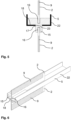
- the Figure 4 shows an alternative design of holding surfaces 10.
- the post 4 more precisely its upper holding section 8, is designed using an omega profile 12.
- the omega profile 12 has two flanges 11 which, unlike the tabs 13 in Figure 3 , run along the entire length of the Omega profile 12 and can be used advantageously as holding surfaces 10.
- the left bar 5 is simply inserted into the Omega profile 12, while the right bar 5 is guided through a through opening 14 which is formed in a side surface of the post 4.
- both bars 5 can be attached one above the other to the paired holding surfaces 10 of the Omega profile 12.
- the holding surfaces 10 designed in pairs grasp the latches 5 on both sides.
- a through-hole 14 either two bolts can be placed, as shown in Figure 3 illustrated, or just a bar, as the embodiment of the Figure 4 shows. How Figure 4 shows, can thus be another, to a first in a through-hole 14 placed bolt 5, adjacent bolts 5 can be mounted on a side of the post 4 opposite the through-hole 14, without using a through-hole 14, namely by means of retaining surfaces 10 formed on the post, which in Figure 4 formed by the flanges 11.
- Such a design is very useful, for example, to compensate for different heights in uneven terrain.
- the Figure 3 The embodiment shown can optionally be interpreted in such a way that the post 4, at least its holding section 8, is formed by a profile 12 with a C-shaped or U-shaped basic shape, whereby in the case of the U-shape the free ends of the profile 12 would be considered as flanges 11.
- flanges 11 are preferred which are intended to serve as holding surfaces 10, as in Figure 4 designed, ie the flanges 11 preferably run in the direction of the bars 5. This design enables the bars 5 to lie flat.
- the omega profile 12 of the post 4 shown can also be understood as a profile 12 with a C-shaped basic form, wherein the holding surfaces 10 shown are designed as flanges 11 at the ends of this profile 12.
- the PV modules 2 are preferably attached to the bars 5, whereby the Figure 2 shown holding elements 15 are provided.
- FIG. 5 shows a detailed cross-sectional view through a holding element 15 according to the invention.
- the holding element 15 is inserted into a through-opening 23 which is formed on an underside of the bolt 5, which is formed by a U-shaped profile 22.
- a contact surface 18 is formed on the holding element 15, with which the holding element 15 lies flat against the inside of the bolt 5.
- the cross-sectional tapering 17, which is formed at the level of the contact surface 18, ensures that the holding element 15 can be inserted into the through-opening 23 up to a defined insertion depth. This ensures, among other things, that the active surfaces 9 of the two PV modules 2 can be mounted at a defined distance from the bar 5, so that shading in particular can be efficiently avoided.
- the PV modules 2 are each inserted with their edges into the two opposing groove sections 16 of the holding element 15.
- the insertion depth is selected so that the active surfaces 9 of the PV modules 2 are not covered or shaded by the holding element 15 and/or the latch 5 up to a certain angle of incidence.
- the holding elements 15 preferably hold the PV modules 2 on both sides in order to ensure secure mounting.
- the holding elements 15 it is sufficient if the holding elements 15 only hold the PV modules on both sides along a certain edge section, as in Figure 6 shown.
- the Figures 7 and 8 illustrate another central aspect, namely arranging the active surfaces 9 of the PV modules 2 at a distance from the posts 4 and/or bars 5.
- the active surfaces 9 of the two PV modules 2 arranged to the left and right of the post 4 are spaced from the post 4 in such a way that sunlight can reach the active surface 9 up to a certain angle of incidence without being shaded by the post 4.
- the angle of incidence corresponds in Figure 7 just the angle that the two shown Sun rays each with the plumb line (horizontally running in Figure 7 ) of the active area 9 in question.
- the active surfaces 9 to the left and right of the post are not the same distance from the post 4. Rather, they are arranged asymmetrically. Due to the slightly larger distance of the active surface 9 of the Figure 7
- the PV module 2 arranged at the top ensures that sunlight from the south does not shade the active surface 9 for larger angles of incidence than is the case for the Figure 7
- the PV module 2 arranged below is designed for sunlight from northern directions. In other words, at the southern edge of a PV module 2, the distance between the PV module 2, more precisely its active surface 9, and the post 4 is chosen to be slightly larger than at its northern edge, as is the case for the two PV modules 2 in Figure 7 illustrate.
- the Figure 8 shows, however, how shading of the active surfaces 9 can be prevented by spacing the active surfaces 9 of the two PV modules 2 shown from the transverse bar 5. Since the Figure 8 represents a cross-section through a horizontally running bar 5, the sunbeam shown falls from above and usually from the side onto the lower PV module 2. By spacing the active surface 9 of the lower PV module 2 from the bar 5, as in Figure 8 shown, a maximum angle of incidence is defined up to which sunlight can hit the active surface 9 without shading. In the Figure 8 This angle of incidence would correspond exactly to the angle formed by the projection onto the vertical section plane of the Figure 8 The incident sunbeam shown in the figure is directed with a plumb line to the active surface 9 (running horizontally in Figure 8 ). It is therefore understood that that the actual angle of incidence between the sunbeam and the slot can usually be larger than the angle that the (in Figure 8 illustrated) projection of this ray in the plane of intersection with the perpendicular of incidence.
- the Figure 8 If the incident angle of the active surfaces of the PV modules shown were pointing straight towards the sun, the Figure 8 The angle of incidence illustrated by the sunbeam corresponds to the position of the sun, i.e. the height of the sun above the horizon measured in degrees. However, sunlight usually shines obliquely from the side onto the PV modules, so that the position of the sun and the angle of incidence differ from each other.
- the two Figure 7 The sun rays shown fall obliquely from the side onto the PV modules 2, whereby here too projections of these rays are made into the horizontal section plane of the Figure 7 are shown.
- an asymmetrical spacing of the PV modules from the bar 5 could be provided.
- shading of the upper active surface 9 by the bar 5 below can be ruled out, since sunlight always falls on the PV modules 2 from above at an angle.
- the upper PV module 2 could therefore move close to the bar 5 until the active surface 9 is just not covered by the bar 5.
- the Figure 9 finally explains further configurations of the photovoltaic system 1, in particular the spacing of the rows 20 of the PV system 1.
- the PV modules 2 with the supporting structure 3 essentially form a plane.
- the PV modules 2 of a row 20 thus also essentially form a plane, whereby this plane can be aligned in particular in a north-south direction, as shown in Figure 9
- the situation shown may occur, i.e. that a portion of a row 20 (here the lower PV modules of the right row 20) is shaded by an adjacent row 20 (here the left row 20).
- FIG. 9 As through the two rays of sun in Figure 9 As indicated, the shading increases the lower the sun is. Therefore, a Figure 9 shown embodiment is preferred, in which the distance designated B between the two rows 20 is more than three times the maximum height of an active area 9 of the PV system 1. This maximum height corresponds in Figure 9 exactly the vertical distance A, which defines the distance between a highest and a lowest point, each within the active areas 9 of the left row 20.
- the large horizontal distance B between the two rows 20 thus shows how the upper sunbeam in Figure 9 shows, ensures that even when the sun is low, only a portion of the right row 20 is shaded, so that at least the upper active surfaces 9 of the right row 20 in Figure 9 can still be used to generate electricity.
- a further advantage of the spacing of the rows 20 of the PV system 1 is the cultivation space 19 that is created between the rows, as this can be used for agricultural purposes, for example.
- the PV modules 2 are thus arranged at a height C above the ground (cf. Figure 9 )
- damage to the same caused by falling rocks can be avoided when the open space for management 19 is used for agricultural purposes.
- this design largely protects the lower active areas 9 of the PV system from being shaded by vegetation or plants in the open space for management 19.
- the open space 26 thus creates the necessary conditions for the agricultural use of the open space for management 19 without any significant loss in electricity production.
Landscapes
- Engineering & Computer Science (AREA)
- General Engineering & Computer Science (AREA)
- Mechanical Engineering (AREA)
- Photovoltaic Devices (AREA)
- Roof Covering Using Slabs Or Stiff Sheets (AREA)
- Connection Of Plates (AREA)
- Supports For Plants (AREA)
- Foundations (AREA)
- Optical Couplings Of Light Guides (AREA)
- Prostheses (AREA)
- Radar Systems Or Details Thereof (AREA)
Priority Applications (3)
| Application Number | Priority Date | Filing Date | Title |
|---|---|---|---|
| RS20241190A RS66145B1 (sr) | 2016-12-23 | 2017-12-20 | Fotonaponski sistem |
| HRP20241481TT HRP20241481T1 (hr) | 2016-12-23 | 2017-12-20 | Fotonaponski sustav |
| MA52668A MA52668B1 (fr) | 2016-12-23 | 2017-12-20 | Installation photovoltaïque |
Applications Claiming Priority (3)
| Application Number | Priority Date | Filing Date | Title |
|---|---|---|---|
| DE102016015436.5A DE102016015436A1 (de) | 2016-12-23 | 2016-12-23 | Photovoltaik-Anlage und zugehörige Verwendung |
| EP17822277.4A EP3560098B1 (de) | 2016-12-23 | 2017-12-20 | Photovoltaik-anlage und zugehörige verwendung |
| PCT/EP2017/083813 WO2018115120A2 (de) | 2016-12-23 | 2017-12-20 | Photovoltaik-anlage und zugehörige verwendung |
Related Parent Applications (2)
| Application Number | Title | Priority Date | Filing Date |
|---|---|---|---|
| EP17822277.4A Division EP3560098B1 (de) | 2016-12-23 | 2017-12-20 | Photovoltaik-anlage und zugehörige verwendung |
| EP17822277.4A Division-Into EP3560098B1 (de) | 2016-12-23 | 2017-12-20 | Photovoltaik-anlage und zugehörige verwendung |
Publications (3)
| Publication Number | Publication Date |
|---|---|
| EP3683960A1 EP3683960A1 (de) | 2020-07-22 |
| EP3683960B1 true EP3683960B1 (de) | 2024-07-31 |
| EP3683960C0 EP3683960C0 (de) | 2024-07-31 |
Family
ID=60857079
Family Applications (4)
| Application Number | Title | Priority Date | Filing Date |
|---|---|---|---|
| EP20157472.0A Active EP3683960B1 (de) | 2016-12-23 | 2017-12-20 | Photovoltaik-anlage |
| EP17822277.4A Active EP3560098B1 (de) | 2016-12-23 | 2017-12-20 | Photovoltaik-anlage und zugehörige verwendung |
| EP20157474.6A Active EP3687060B1 (de) | 2016-12-23 | 2017-12-20 | Photovoltaik-anlage |
| EP20179321.3A Active EP3742602B1 (de) | 2016-12-23 | 2017-12-20 | Photovoltaik-anlage und zugehörige verwendung |
Family Applications After (3)
| Application Number | Title | Priority Date | Filing Date |
|---|---|---|---|
| EP17822277.4A Active EP3560098B1 (de) | 2016-12-23 | 2017-12-20 | Photovoltaik-anlage und zugehörige verwendung |
| EP20157474.6A Active EP3687060B1 (de) | 2016-12-23 | 2017-12-20 | Photovoltaik-anlage |
| EP20179321.3A Active EP3742602B1 (de) | 2016-12-23 | 2017-12-20 | Photovoltaik-anlage und zugehörige verwendung |
Country Status (23)
| Country | Link |
|---|---|
| US (3) | US11411525B2 (enExample) |
| EP (4) | EP3683960B1 (enExample) |
| JP (4) | JP7104706B2 (enExample) |
| CN (1) | CN110214414B (enExample) |
| AU (3) | AU2017384503B2 (enExample) |
| CA (1) | CA3048086C (enExample) |
| CL (1) | CL2019001732A1 (enExample) |
| DE (1) | DE102016015436A1 (enExample) |
| DK (1) | DK3560098T3 (enExample) |
| EA (3) | EA202193201A2 (enExample) |
| ES (4) | ES2826860T3 (enExample) |
| HR (4) | HRP20250576T1 (enExample) |
| HU (4) | HUE050994T2 (enExample) |
| LT (1) | LT3560098T (enExample) |
| MA (3) | MA52668B1 (enExample) |
| MX (1) | MX2019006763A (enExample) |
| PL (4) | PL3683960T3 (enExample) |
| PT (1) | PT3560098T (enExample) |
| RS (4) | RS60950B1 (enExample) |
| SI (1) | SI3560098T1 (enExample) |
| UA (1) | UA124394C2 (enExample) |
| WO (1) | WO2018115120A2 (enExample) |
| ZA (1) | ZA201903333B (enExample) |
Families Citing this family (29)
| Publication number | Priority date | Publication date | Assignee | Title |
|---|---|---|---|---|
| US11165384B1 (en) * | 2018-05-18 | 2021-11-02 | Joseph McCABE | Method for hanging PV modules |
| US11601086B2 (en) | 2019-11-01 | 2023-03-07 | RBI Solar, Inc. | Solar canopy system with roll-formed structural components |
| WO2020198579A2 (en) * | 2019-03-27 | 2020-10-01 | Fcx Solar, Llc | Roll-formed solar canopy structures and foundation structures and methods |
| DE102019113016A1 (de) | 2019-05-17 | 2020-11-19 | Heliatek Gmbh | Säule mit mindestens einem photovoltaischen Element und Verwendung eines photovoltaischen Elements an einer Säule |
| US12119784B2 (en) * | 2019-06-18 | 2024-10-15 | Sunny Rich Agric. & Biotech Co., Ltd. | Array solar power generation device |
| DE202020104397U1 (de) | 2020-07-30 | 2021-11-03 | Rudolf Hörmann GmbH & Co.KG | Photovoltaikanlage |
| CN116134724A (zh) | 2020-08-04 | 2023-05-16 | 德国维康公司 | 具有线缆承载结构的光伏设备 |
| US11689147B2 (en) | 2020-08-20 | 2023-06-27 | Parasol Structures Inc. | Photovoltaic module mounting structure |
| CH717977A1 (de) | 2020-10-16 | 2022-04-29 | Enecolo Ag | Solarmodul mit freistehender Solarmodullamelle und Verfahren zu dessen Herstellung. |
| JP7061296B1 (ja) * | 2021-02-04 | 2022-04-28 | 株式会社アルシス | 発電フェンス及びその施工方法 |
| PL4068620T3 (pl) | 2021-03-30 | 2023-07-24 | Voestalpine Sadef Nv | Ramy dla pionowego układu solarnego |
| FR3132186B1 (fr) * | 2022-01-24 | 2024-05-10 | Engie | Système photovoltaïque vertical et procédé d’installation d’un tel système |
| IL292736B2 (en) | 2022-05-03 | 2023-05-01 | Sun Terra Ltd | A stand for a vertical solar system |
| EP4434154A1 (de) * | 2022-08-29 | 2024-09-25 | C.W.F. GmbH | Tragvorrichtung für ein solarsystem und verfahren zur montage eines solarsystems |
| FR3139379B1 (fr) * | 2022-09-06 | 2025-07-25 | Engie | Système photovoltaïque vertical et procédé d’installation d’un tel système |
| DE102022127018A1 (de) * | 2022-10-14 | 2024-04-25 | Next2Sun Technology GmbH | Modulhalterung und zugehörige Photovoltaik-Anlage |
| EP4358398A1 (en) | 2022-10-19 | 2024-04-24 | Solyco Technology GmbH | Mounting kit, photovoltaic module arrangement and assembly method |
| DE202022107183U1 (de) | 2022-12-22 | 2023-02-22 | Next2Sun Technology GmbH | Tragkonstruktion für eine Photovoltaik-Anlage |
| JP2025540491A (ja) | 2022-12-22 | 2025-12-11 | ネクスト2サン テクノロジー ゲーエムベーハー | 太陽光発電装置のための支持構造 |
| EP4390267B1 (de) | 2022-12-22 | 2025-10-01 | Next2Sun Technology GmbH | Tragkonstruktion für eine photovoltaik-anlage |
| EP4655873A1 (de) | 2023-01-24 | 2025-12-03 | Eco-Invention AG | Photovoltaikanlage für freiland |
| KR102566049B1 (ko) * | 2023-02-07 | 2023-08-11 | 김명수 | 레이저 용접을 이용한 태양전지 패널 지지대 제조 방법 |
| EP4472065A1 (en) * | 2023-05-29 | 2024-12-04 | Tecna Energy Srl | Field of bifacial photovoltaic solar panels |
| IT202300010878A1 (it) * | 2023-05-29 | 2024-11-29 | Tecna Energy Srl | Campo di pannelli solari fotovoltaici bifacciali |
| IL303637A (en) * | 2023-06-12 | 2025-01-01 | Sun Terra Ltd | Frame for a double-sided solar panel |
| DE102023206677B4 (de) | 2023-07-13 | 2025-11-06 | Hochschule für Technik und Wirtschaft Dresden, Körperschaft des öffentlichen Rechts | System bei dem mehrere nebeneinander in einem Abstand und parallel zueinander angeordnete Photovoltaikmodulreihen auf einer landwirtschaftlich genutzten Fläche installiert sind |
| CN117090238A (zh) * | 2023-08-21 | 2023-11-21 | 中电建宁夏工程有限公司 | 沙漠光伏支架基础phc管桩施工装置 |
| DE102023130403A1 (de) | 2023-11-03 | 2025-05-08 | Novo-Tech Gmbh & Co. Kg | Photovoltaik-Anlage und Verfahren zur Montage einer Photovoltaik-Anlage |
| CH721469A1 (fr) * | 2023-12-22 | 2025-06-30 | Lightswing Solar Sarl | Installation solaire basculante |
Family Cites Families (38)
| Publication number | Priority date | Publication date | Assignee | Title |
|---|---|---|---|---|
| JPS5426654Y2 (enExample) * | 1974-07-15 | 1979-09-03 | ||
| US3955801A (en) * | 1975-08-01 | 1976-05-11 | Vinylife Industries | Pre-fabricated fences |
| JPS5424509Y2 (enExample) * | 1977-03-25 | 1979-08-18 | ||
| JPS5542720A (en) | 1978-09-12 | 1980-03-26 | Kobe Steel Ltd | Rotary cutter |
| JPS5542720U (enExample) * | 1978-09-14 | 1980-03-19 | ||
| DE9314973U1 (de) * | 1993-10-02 | 1994-05-26 | Eisenschenk, Johann, 93491 Stamsried | Im Boden zu verankerndes Konstruktionselement sowie Bodenanker für ein solches Konstruktionselement |
| JPH08170790A (ja) | 1994-12-19 | 1996-07-02 | Central Res Inst Of Electric Power Ind | 太陽電池モジュール用架台 |
| US7267324B2 (en) * | 2000-01-13 | 2007-09-11 | Young Warren F | Ranch fence |
| JP2002076416A (ja) * | 2000-08-25 | 2002-03-15 | Hitachi Ltd | 両面受光型太陽電池アレイ |
| JP3958518B2 (ja) * | 2000-12-07 | 2007-08-15 | 積水樹脂株式会社 | 太陽光発電装置付き防雪柵 |
| JP4208421B2 (ja) * | 2001-02-08 | 2009-01-14 | 三洋電機株式会社 | 太陽電池アレイの設置方法 |
| DE10114586A1 (de) * | 2001-03-24 | 2002-10-02 | Guenter Pfeiffer | Anordnung und Verfahren zur Erzeugung von Solarstrom zur Nutzung in Heizungs- und/oder Warmwasseraufbereitungsanlagen |
| JP2003229591A (ja) * | 2002-02-06 | 2003-08-15 | Sekisui Jushi Co Ltd | 太陽電池の冠雪防止構造及びその冠雪防止構造を備えた太陽電池装置 |
| JP2004335903A (ja) * | 2003-05-12 | 2004-11-25 | Hitachi Ltd | 両面受光型太陽電池アレイ |
| JP3985837B2 (ja) * | 2005-12-01 | 2007-10-03 | 株式会社日立製作所 | 太陽光発電装置及びその設置方法 |
| FR2915345B1 (fr) * | 2007-04-20 | 2009-07-03 | Imphy Alloys Sa | Bati support d'un panneau electriquement actif tel qu'un panneau photovoltaique |
| JP3137716U (ja) * | 2007-09-25 | 2007-12-06 | グローベン株式会社 | ガラスフェンスの取付構造 |
| JP5451989B2 (ja) * | 2008-06-10 | 2014-03-26 | 三菱電機株式会社 | 太陽電池架台装置 |
| US9494343B2 (en) * | 2009-07-07 | 2016-11-15 | Rodney Harold Thomas | Solar capture mounting systems and methods |
| DE202010017184U1 (de) * | 2010-01-22 | 2011-04-07 | Kellner, Peter | Vorrichtung zur Befestigung eines Solarpaneels und/oder zur Befestigung einer Windkraftanlage |
| JP5263795B2 (ja) * | 2010-03-25 | 2013-08-14 | シャープ株式会社 | 太陽電池モジュールの取付構造 |
| WO2011156020A1 (en) * | 2010-06-10 | 2011-12-15 | Wolter James F | Solar panel system with monocoque supporting structure |
| US8782996B2 (en) * | 2010-06-11 | 2014-07-22 | Douglas Moyles | Systems and methods for ground mounted solar array |
| US9291369B2 (en) * | 2010-12-09 | 2016-03-22 | Solarcity Corporation | Skirt for photovoltaic arrays |
| US20130008485A1 (en) | 2011-07-08 | 2013-01-10 | Luo Chia Ching | Solar generator apparatus with sun-tracking function |
| US8671631B2 (en) | 2011-10-17 | 2014-03-18 | Pv Hardware Llc | Panel mounting system |
| JP2013143409A (ja) | 2012-01-10 | 2013-07-22 | Systec:Kk | 太陽光発電設置物 |
| DE102012002551A1 (de) | 2012-02-09 | 2013-08-14 | Fraunhofer-Gesellschaft zur Förderung der angewandten Forschung e.V. | Verfahren zur simultanen Kultivierung von Nutzpflanzen und energetischen Nutzung von Sonnenlicht |
| US9027248B2 (en) * | 2012-04-23 | 2015-05-12 | Eco Powerdeck, Inc. | Solar panel mounting apparatus and method |
| EP2848752A4 (en) * | 2012-04-26 | 2016-01-27 | Kyocera Corp | SOLAR CELL DEVICE |
| CH706583A1 (de) * | 2012-05-31 | 2013-12-13 | Le Light Energy Systems Ag | Solaranlage. |
| CN102881752A (zh) * | 2012-08-27 | 2013-01-16 | 友达光电股份有限公司 | 太阳能装置 |
| KR101460719B1 (ko) * | 2012-08-28 | 2014-11-13 | 엘지전자 주식회사 | 지지 프레임 및 이를 포함하는 태양광 발전 장치 |
| JP2014236199A (ja) * | 2013-06-05 | 2014-12-15 | ミライアル株式会社 | 太陽光発電システム |
| CN203514953U (zh) * | 2013-08-06 | 2014-04-02 | 南京汉能光伏有限公司 | 一种光伏围栏 |
| EP3095139B1 (en) * | 2014-01-13 | 2017-12-27 | SolarCity Corporation | High efficiency solar panel |
| DE202014105516U1 (de) | 2014-11-17 | 2014-12-23 | Solarworld Ag | Photovoltaik-Anlage, Modulhalter-System und Reflektor |
| CN206349960U (zh) * | 2016-08-20 | 2017-07-21 | 江苏尚特光伏科技有限公司 | 太阳能光伏支架 |
-
2016
- 2016-12-23 DE DE102016015436.5A patent/DE102016015436A1/de active Granted
-
2017
- 2017-12-20 CN CN201780078621.3A patent/CN110214414B/zh active Active
- 2017-12-20 RS RS20201257A patent/RS60950B1/sr unknown
- 2017-12-20 AU AU2017384503A patent/AU2017384503B2/en active Active
- 2017-12-20 HU HUE17822277A patent/HUE050994T2/hu unknown
- 2017-12-20 HU HUE20157474A patent/HUE069411T2/hu unknown
- 2017-12-20 HU HUE20179321A patent/HUE071316T2/hu unknown
- 2017-12-20 ES ES17822277T patent/ES2826860T3/es active Active
- 2017-12-20 EA EA202193201A patent/EA202193201A2/ru unknown
- 2017-12-20 MA MA52668A patent/MA52668B1/fr unknown
- 2017-12-20 EP EP20157472.0A patent/EP3683960B1/de active Active
- 2017-12-20 ES ES20157474T patent/ES3000162T3/es active Active
- 2017-12-20 EA EA202190002A patent/EA039661B1/ru unknown
- 2017-12-20 ES ES20157472T patent/ES2994069T3/es active Active
- 2017-12-20 WO PCT/EP2017/083813 patent/WO2018115120A2/de not_active Ceased
- 2017-12-20 US US16/471,924 patent/US11411525B2/en active Active
- 2017-12-20 PL PL20157472.0T patent/PL3683960T3/pl unknown
- 2017-12-20 JP JP2019534849A patent/JP7104706B2/ja active Active
- 2017-12-20 PT PT178222774T patent/PT3560098T/pt unknown
- 2017-12-20 HR HRP20250576TT patent/HRP20250576T1/hr unknown
- 2017-12-20 HR HRP20241481TT patent/HRP20241481T1/hr unknown
- 2017-12-20 SI SI201730470T patent/SI3560098T1/sl unknown
- 2017-12-20 RS RS20250453A patent/RS66838B1/sr unknown
- 2017-12-20 MX MX2019006763A patent/MX2019006763A/es unknown
- 2017-12-20 HU HUE20157472A patent/HUE068881T2/hu unknown
- 2017-12-20 HR HRP20201655TT patent/HRP20201655T1/hr unknown
- 2017-12-20 DK DK17822277.4T patent/DK3560098T3/da active
- 2017-12-20 EP EP17822277.4A patent/EP3560098B1/de active Active
- 2017-12-20 PL PL17822277T patent/PL3560098T3/pl unknown
- 2017-12-20 MA MA52652A patent/MA52652B1/fr unknown
- 2017-12-20 MA MA47224A patent/MA47224B1/fr unknown
- 2017-12-20 HR HRP20241556TT patent/HRP20241556T1/hr unknown
- 2017-12-20 CA CA3048086A patent/CA3048086C/en active Active
- 2017-12-20 PL PL20179321.3T patent/PL3742602T3/pl unknown
- 2017-12-20 ES ES20179321T patent/ES3028408T3/es active Active
- 2017-12-20 RS RS20241282A patent/RS66203B1/sr unknown
- 2017-12-20 UA UAA201907817A patent/UA124394C2/uk unknown
- 2017-12-20 LT LTEP17822277.4T patent/LT3560098T/lt unknown
- 2017-12-20 EP EP20157474.6A patent/EP3687060B1/de active Active
- 2017-12-20 PL PL20157474.6T patent/PL3687060T3/pl unknown
- 2017-12-20 RS RS20241190A patent/RS66145B1/sr unknown
- 2017-12-20 EP EP20179321.3A patent/EP3742602B1/de active Active
- 2017-12-20 EA EA201991298A patent/EA037282B1/ru unknown
-
2019
- 2019-05-27 ZA ZA2019/03333A patent/ZA201903333B/en unknown
- 2019-06-20 CL CL2019001732A patent/CL2019001732A1/es unknown
-
2022
- 2022-07-08 JP JP2022110400A patent/JP7500660B2/ja active Active
- 2022-07-11 US US17/861,381 patent/US20220345073A1/en not_active Abandoned
-
2023
- 2023-02-03 AU AU2023200555A patent/AU2023200555B2/en active Active
- 2023-11-17 US US18/512,378 patent/US20240088822A1/en active Pending
-
2024
- 2024-02-29 JP JP2024030059A patent/JP7717875B2/ja active Active
- 2024-02-29 JP JP2024030060A patent/JP7717876B2/ja active Active
- 2024-09-25 AU AU2024220040A patent/AU2024220040A1/en active Pending
Also Published As
Similar Documents
| Publication | Publication Date | Title |
|---|---|---|
| EP3683960B1 (de) | Photovoltaik-anlage | |
| AT524070B1 (de) | Photovoltaikanlage | |
| DE202007012570U1 (de) | Unterkonstruktion für Solarfreiflächenanlagen | |
| DE102007023177A1 (de) | Unterkonstruktion für PV-Anlage | |
| EP2296190A2 (de) | Anordnung, Unterkonstruktion und Photovoltaikanlage | |
| EP2398064A1 (de) | Photovoltaische Freiflächenanlage für die Landwirtschaft | |
| DE202014009173U1 (de) | Einteiliges Tragsystem zur Anordnung einer Vielzahl von Solarmodulen/Solarkollektoren auf Dachflächen oder Freiflächen | |
| DE202016008027U1 (de) | Photovoltaik-Anlage und zugehörige Verwendung | |
| DE102013216173A1 (de) | Anordnung und Verfahren zur Halterung mindestens eines Photovoltaikmoduls | |
| EP2526350B1 (de) | Fundamentsystem für solarpaneele mit vormontierbaren beschlagteilen | |
| WO2014029499A1 (de) | Giebeldachförmiger pv-generator auf bodenstützelementen | |
| DE102012016797B4 (de) | Dachunterbau in Zickzackform | |
| EP2037194B1 (de) | Unterkonstruktion für Solarfreiflächenanlagen | |
| EP2554925B1 (de) | Stützelement für ein Solarmodul | |
| DE202006009884U1 (de) | Unterkonstruktion für PV-Anlage | |
| DE102012016671A1 (de) | PV-Generator mit Traufenablauf | |
| DE202012005413U1 (de) | Ausrichtbares Fundamentsystem für Solarpaneele | |
| DE202013006006U1 (de) | Reihenverbinder für Solarmodule | |
| AT18252U1 (de) | Tragkonstruktionsmontagesystem für Photovoltaik-Module | |
| WO2016174272A1 (de) | Modularer solarkollektor | |
| WO2009033547A1 (de) | Unterkonstruktion für solarfreiflächenanlagen | |
| EP2808620A2 (de) | Trägervorrichtung für Photovoltaik- oder Solarkollektormodul | |
| DE102023132121A1 (de) | Photovoltaikgestell, Photovoltaikanlage | |
| DE102011052222B4 (de) | Photovoltaikanlage | |
| EP3961121A1 (de) | Unterkonstruktion zur montage von sich selbsttragenden photovoltaikmodulen |
Legal Events
| Date | Code | Title | Description |
|---|---|---|---|
| REG | Reference to a national code |
Ref country code: HR Ref legal event code: TUEP Ref document number: P20241481T Country of ref document: HR |
|
| PUAI | Public reference made under article 153(3) epc to a published international application that has entered the european phase |
Free format text: ORIGINAL CODE: 0009012 |
|
| STAA | Information on the status of an ep patent application or granted ep patent |
Free format text: STATUS: THE APPLICATION HAS BEEN PUBLISHED |
|
| AC | Divisional application: reference to earlier application |
Ref document number: 3560098 Country of ref document: EP Kind code of ref document: P |
|
| AK | Designated contracting states |
Kind code of ref document: A1 Designated state(s): AL AT BE BG CH CY CZ DE DK EE ES FI FR GB GR HR HU IE IS IT LI LT LU LV MC MK MT NL NO PL PT RO RS SE SI SK SM TR |
|
| STAA | Information on the status of an ep patent application or granted ep patent |
Free format text: STATUS: REQUEST FOR EXAMINATION WAS MADE |
|
| 17P | Request for examination filed |
Effective date: 20210108 |
|
| RAV | Requested validation state of the european patent: fee paid |
Extension state: MA Effective date: 20210108 Extension state: TN Effective date: 20210108 |
|
| RBV | Designated contracting states (corrected) |
Designated state(s): AL AT BE BG CH CY CZ DE DK EE ES FI FR GB GR HR HU IE IS IT LI LT LU LV MC MK MT NL NO PL PT RO RS SE SI SK SM TR |
|
| STAA | Information on the status of an ep patent application or granted ep patent |
Free format text: STATUS: EXAMINATION IS IN PROGRESS |
|
| 17Q | First examination report despatched |
Effective date: 20220407 |
|
| GRAP | Despatch of communication of intention to grant a patent |
Free format text: ORIGINAL CODE: EPIDOSNIGR1 |
|
| STAA | Information on the status of an ep patent application or granted ep patent |
Free format text: STATUS: GRANT OF PATENT IS INTENDED |
|
| INTG | Intention to grant announced |
Effective date: 20240223 |
|
| GRAS | Grant fee paid |
Free format text: ORIGINAL CODE: EPIDOSNIGR3 |
|
| GRAA | (expected) grant |
Free format text: ORIGINAL CODE: 0009210 |
|
| STAA | Information on the status of an ep patent application or granted ep patent |
Free format text: STATUS: THE PATENT HAS BEEN GRANTED |
|
| AC | Divisional application: reference to earlier application |
Ref document number: 3560098 Country of ref document: EP Kind code of ref document: P |
|
| AK | Designated contracting states |
Kind code of ref document: B1 Designated state(s): AL AT BE BG CH CY CZ DE DK EE ES FI FR GB GR HR HU IE IS IT LI LT LU LV MC MK MT NL NO PL PT RO RS SE SI SK SM TR |
|
| REG | Reference to a national code |
Ref country code: CH Ref legal event code: EP Ref country code: GB Ref legal event code: FG4D Free format text: NOT ENGLISH |
|
| REG | Reference to a national code |
Ref country code: DE Ref legal event code: R096 Ref document number: 502017016317 Country of ref document: DE |
|
| REG | Reference to a national code |
Ref country code: IE Ref legal event code: FG4D Free format text: LANGUAGE OF EP DOCUMENT: GERMAN |
|
| U01 | Request for unitary effect filed |
Effective date: 20240819 |
|
| U07 | Unitary effect registered |
Designated state(s): AT BE BG DE DK EE FI FR IT LT LU LV MT NL PT RO SE SI Effective date: 20240902 |
|
| REG | Reference to a national code |
Ref country code: MA Ref legal event code: VAGR Ref document number: 52668 Country of ref document: MA Kind code of ref document: B1 |
|
| REG | Reference to a national code |
Ref country code: SK Ref legal event code: T3 Ref document number: E 45242 Country of ref document: SK |
|
| REG | Reference to a national code |
Ref country code: GR Ref legal event code: EP Ref document number: 20240402520 Country of ref document: GR Effective date: 20241209 |
|
| REG | Reference to a national code |
Ref country code: HR Ref legal event code: T1PR Ref document number: P20241481 Country of ref document: HR |
|
| PGFP | Annual fee paid to national office [announced via postgrant information from national office to epo] |
Ref country code: NO Payment date: 20241216 Year of fee payment: 8 |
|
| U20 | Renewal fee for the european patent with unitary effect paid |
Year of fee payment: 8 Effective date: 20241211 |
|
| PGFP | Annual fee paid to national office [announced via postgrant information from national office to epo] |
Ref country code: PL Payment date: 20241213 Year of fee payment: 8 Ref country code: GR Payment date: 20241213 Year of fee payment: 8 |
|
| REG | Reference to a national code |
Ref country code: ES Ref legal event code: FG2A Ref document number: 2994069 Country of ref document: ES Kind code of ref document: T3 Effective date: 20250116 |
|
| PGFP | Annual fee paid to national office [announced via postgrant information from national office to epo] |
Ref country code: GB Payment date: 20241218 Year of fee payment: 8 |
|
| REG | Reference to a national code |
Ref country code: HR Ref legal event code: ODRP Ref document number: P20241481 Country of ref document: HR Payment date: 20241211 Year of fee payment: 8 |
|
| PGFP | Annual fee paid to national office [announced via postgrant information from national office to epo] |
Ref country code: HU Payment date: 20241214 Year of fee payment: 8 Ref country code: IS Payment date: 20241213 Year of fee payment: 8 |
|
| PGFP | Annual fee paid to national office [announced via postgrant information from national office to epo] |
Ref country code: HR Payment date: 20241211 Year of fee payment: 8 Ref country code: IE Payment date: 20241212 Year of fee payment: 8 |
|
| PGFP | Annual fee paid to national office [announced via postgrant information from national office to epo] |
Ref country code: SK Payment date: 20241212 Year of fee payment: 8 |
|
| PGFP | Annual fee paid to national office [announced via postgrant information from national office to epo] |
Ref country code: RS Payment date: 20241216 Year of fee payment: 8 |
|
| REG | Reference to a national code |
Ref country code: HU Ref legal event code: AG4A Ref document number: E068881 Country of ref document: HU |
|
| PG25 | Lapsed in a contracting state [announced via postgrant information from national office to epo] |
Ref country code: SM Free format text: LAPSE BECAUSE OF FAILURE TO SUBMIT A TRANSLATION OF THE DESCRIPTION OR TO PAY THE FEE WITHIN THE PRESCRIBED TIME-LIMIT Effective date: 20240731 |
|
| PGFP | Annual fee paid to national office [announced via postgrant information from national office to epo] |
Ref country code: ES Payment date: 20250117 Year of fee payment: 8 |
|
| PGFP | Annual fee paid to national office [announced via postgrant information from national office to epo] |
Ref country code: CH Payment date: 20250101 Year of fee payment: 8 |
|
| PGFP | Annual fee paid to national office [announced via postgrant information from national office to epo] |
Ref country code: CZ Payment date: 20241206 Year of fee payment: 8 |
|
| PGFP | Annual fee paid to national office [announced via postgrant information from national office to epo] |
Ref country code: TR Payment date: 20241212 Year of fee payment: 8 |
|
| PLBE | No opposition filed within time limit |
Free format text: ORIGINAL CODE: 0009261 |
|
| STAA | Information on the status of an ep patent application or granted ep patent |
Free format text: STATUS: NO OPPOSITION FILED WITHIN TIME LIMIT |
|
| PG25 | Lapsed in a contracting state [announced via postgrant information from national office to epo] |
Ref country code: MC Free format text: LAPSE BECAUSE OF FAILURE TO SUBMIT A TRANSLATION OF THE DESCRIPTION OR TO PAY THE FEE WITHIN THE PRESCRIBED TIME-LIMIT Effective date: 20240731 |
|
| 26N | No opposition filed |
Effective date: 20250501 |
|
| VSFP | Annual fee paid to validation state [announced via postgrant information from national office to epo] |
Ref country code: MA Payment date: 20241220 Year of fee payment: 8 |
|
| REG | Reference to a national code |
Ref country code: CH Ref legal event code: U11 Free format text: ST27 STATUS EVENT CODE: U-0-0-U10-U11 (AS PROVIDED BY THE NATIONAL OFFICE) Effective date: 20260101 |