EP3683490B1 - Hydrogen filling system and hydrogen filling method - Google Patents
Hydrogen filling system and hydrogen filling method Download PDFInfo
- Publication number
- EP3683490B1 EP3683490B1 EP20151037.7A EP20151037A EP3683490B1 EP 3683490 B1 EP3683490 B1 EP 3683490B1 EP 20151037 A EP20151037 A EP 20151037A EP 3683490 B1 EP3683490 B1 EP 3683490B1
- Authority
- EP
- European Patent Office
- Prior art keywords
- filling
- communication
- pressure
- hydrogen
- vehicle
- Prior art date
- Legal status (The legal status is an assumption and is not a legal conclusion. Google has not performed a legal analysis and makes no representation as to the accuracy of the status listed.)
- Active
Links
Images




Classifications
-
- B—PERFORMING OPERATIONS; TRANSPORTING
- B67—OPENING, CLOSING OR CLEANING BOTTLES, JARS OR SIMILAR CONTAINERS; LIQUID HANDLING
- B67D—DISPENSING, DELIVERING OR TRANSFERRING LIQUIDS, NOT OTHERWISE PROVIDED FOR
- B67D7/00—Apparatus or devices for transferring liquids from bulk storage containers or reservoirs into vehicles or into portable containers, e.g. for retail sale purposes
- B67D7/06—Details or accessories
- B67D7/32—Arrangements of safety or warning devices; Means for preventing unauthorised delivery of liquid
- B67D7/3245—Arrangements of safety or warning devices; Means for preventing unauthorised delivery of liquid relating to the transfer method
-
- F—MECHANICAL ENGINEERING; LIGHTING; HEATING; WEAPONS; BLASTING
- F17—STORING OR DISTRIBUTING GASES OR LIQUIDS
- F17C—VESSELS FOR CONTAINING OR STORING COMPRESSED, LIQUEFIED OR SOLIDIFIED GASES; FIXED-CAPACITY GAS-HOLDERS; FILLING VESSELS WITH, OR DISCHARGING FROM VESSELS, COMPRESSED, LIQUEFIED, OR SOLIDIFIED GASES
- F17C5/00—Methods or apparatus for filling containers with liquefied, solidified, or compressed gases under pressures
- F17C5/06—Methods or apparatus for filling containers with liquefied, solidified, or compressed gases under pressures for filling with compressed gases
-
- B—PERFORMING OPERATIONS; TRANSPORTING
- B60—VEHICLES IN GENERAL
- B60S—SERVICING, CLEANING, REPAIRING, SUPPORTING, LIFTING, OR MANOEUVRING OF VEHICLES, NOT OTHERWISE PROVIDED FOR
- B60S5/00—Servicing, maintaining, repairing, or refitting of vehicles
- B60S5/02—Supplying fuel to vehicles; General disposition of plant in filling stations
-
- B—PERFORMING OPERATIONS; TRANSPORTING
- B67—OPENING, CLOSING OR CLEANING BOTTLES, JARS OR SIMILAR CONTAINERS; LIQUID HANDLING
- B67D—DISPENSING, DELIVERING OR TRANSFERRING LIQUIDS, NOT OTHERWISE PROVIDED FOR
- B67D7/00—Apparatus or devices for transferring liquids from bulk storage containers or reservoirs into vehicles or into portable containers, e.g. for retail sale purposes
- B67D7/04—Apparatus or devices for transferring liquids from bulk storage containers or reservoirs into vehicles or into portable containers, e.g. for retail sale purposes for transferring fuels, lubricants or mixed fuels and lubricants
-
- F—MECHANICAL ENGINEERING; LIGHTING; HEATING; WEAPONS; BLASTING
- F17—STORING OR DISTRIBUTING GASES OR LIQUIDS
- F17C—VESSELS FOR CONTAINING OR STORING COMPRESSED, LIQUEFIED OR SOLIDIFIED GASES; FIXED-CAPACITY GAS-HOLDERS; FILLING VESSELS WITH, OR DISCHARGING FROM VESSELS, COMPRESSED, LIQUEFIED, OR SOLIDIFIED GASES
- F17C13/00—Details of vessels or of the filling or discharging of vessels
- F17C13/02—Special adaptations of indicating, measuring, or monitoring equipment
- F17C13/025—Special adaptations of indicating, measuring, or monitoring equipment having the pressure as the parameter
-
- F—MECHANICAL ENGINEERING; LIGHTING; HEATING; WEAPONS; BLASTING
- F17—STORING OR DISTRIBUTING GASES OR LIQUIDS
- F17C—VESSELS FOR CONTAINING OR STORING COMPRESSED, LIQUEFIED OR SOLIDIFIED GASES; FIXED-CAPACITY GAS-HOLDERS; FILLING VESSELS WITH, OR DISCHARGING FROM VESSELS, COMPRESSED, LIQUEFIED, OR SOLIDIFIED GASES
- F17C13/00—Details of vessels or of the filling or discharging of vessels
- F17C13/02—Special adaptations of indicating, measuring, or monitoring equipment
- F17C13/026—Special adaptations of indicating, measuring, or monitoring equipment having the temperature as the parameter
-
- F—MECHANICAL ENGINEERING; LIGHTING; HEATING; WEAPONS; BLASTING
- F17—STORING OR DISTRIBUTING GASES OR LIQUIDS
- F17C—VESSELS FOR CONTAINING OR STORING COMPRESSED, LIQUEFIED OR SOLIDIFIED GASES; FIXED-CAPACITY GAS-HOLDERS; FILLING VESSELS WITH, OR DISCHARGING FROM VESSELS, COMPRESSED, LIQUEFIED, OR SOLIDIFIED GASES
- F17C5/00—Methods or apparatus for filling containers with liquefied, solidified, or compressed gases under pressures
- F17C5/002—Automated filling apparatus
- F17C5/007—Automated filling apparatus for individual gas tanks or containers, e.g. in vehicles
-
- H—ELECTRICITY
- H04—ELECTRIC COMMUNICATION TECHNIQUE
- H04L—TRANSMISSION OF DIGITAL INFORMATION, e.g. TELEGRAPHIC COMMUNICATION
- H04L41/00—Arrangements for maintenance, administration or management of data switching networks, e.g. of packet switching networks
- H04L41/06—Management of faults, events, alarms or notifications
- H04L41/0654—Management of faults, events, alarms or notifications using network fault recovery
- H04L41/0663—Performing the actions predefined by failover planning, e.g. switching to standby network elements
-
- F—MECHANICAL ENGINEERING; LIGHTING; HEATING; WEAPONS; BLASTING
- F17—STORING OR DISTRIBUTING GASES OR LIQUIDS
- F17C—VESSELS FOR CONTAINING OR STORING COMPRESSED, LIQUEFIED OR SOLIDIFIED GASES; FIXED-CAPACITY GAS-HOLDERS; FILLING VESSELS WITH, OR DISCHARGING FROM VESSELS, COMPRESSED, LIQUEFIED, OR SOLIDIFIED GASES
- F17C2221/00—Handled fluid, in particular type of fluid
- F17C2221/01—Pure fluids
- F17C2221/012—Hydrogen
-
- F—MECHANICAL ENGINEERING; LIGHTING; HEATING; WEAPONS; BLASTING
- F17—STORING OR DISTRIBUTING GASES OR LIQUIDS
- F17C—VESSELS FOR CONTAINING OR STORING COMPRESSED, LIQUEFIED OR SOLIDIFIED GASES; FIXED-CAPACITY GAS-HOLDERS; FILLING VESSELS WITH, OR DISCHARGING FROM VESSELS, COMPRESSED, LIQUEFIED, OR SOLIDIFIED GASES
- F17C2223/00—Handled fluid before transfer, i.e. state of fluid when stored in the vessel or before transfer from the vessel
- F17C2223/01—Handled fluid before transfer, i.e. state of fluid when stored in the vessel or before transfer from the vessel characterised by the phase
- F17C2223/0107—Single phase
- F17C2223/0123—Single phase gaseous, e.g. CNG, GNC
-
- F—MECHANICAL ENGINEERING; LIGHTING; HEATING; WEAPONS; BLASTING
- F17—STORING OR DISTRIBUTING GASES OR LIQUIDS
- F17C—VESSELS FOR CONTAINING OR STORING COMPRESSED, LIQUEFIED OR SOLIDIFIED GASES; FIXED-CAPACITY GAS-HOLDERS; FILLING VESSELS WITH, OR DISCHARGING FROM VESSELS, COMPRESSED, LIQUEFIED, OR SOLIDIFIED GASES
- F17C2223/00—Handled fluid before transfer, i.e. state of fluid when stored in the vessel or before transfer from the vessel
- F17C2223/03—Handled fluid before transfer, i.e. state of fluid when stored in the vessel or before transfer from the vessel characterised by the pressure level
- F17C2223/036—Very high pressure (>80 bar)
-
- F—MECHANICAL ENGINEERING; LIGHTING; HEATING; WEAPONS; BLASTING
- F17—STORING OR DISTRIBUTING GASES OR LIQUIDS
- F17C—VESSELS FOR CONTAINING OR STORING COMPRESSED, LIQUEFIED OR SOLIDIFIED GASES; FIXED-CAPACITY GAS-HOLDERS; FILLING VESSELS WITH, OR DISCHARGING FROM VESSELS, COMPRESSED, LIQUEFIED, OR SOLIDIFIED GASES
- F17C2225/00—Handled fluid after transfer, i.e. state of fluid after transfer from the vessel
- F17C2225/01—Handled fluid after transfer, i.e. state of fluid after transfer from the vessel characterised by the phase
- F17C2225/0107—Single phase
- F17C2225/0123—Single phase gaseous, e.g. CNG, GNC
-
- F—MECHANICAL ENGINEERING; LIGHTING; HEATING; WEAPONS; BLASTING
- F17—STORING OR DISTRIBUTING GASES OR LIQUIDS
- F17C—VESSELS FOR CONTAINING OR STORING COMPRESSED, LIQUEFIED OR SOLIDIFIED GASES; FIXED-CAPACITY GAS-HOLDERS; FILLING VESSELS WITH, OR DISCHARGING FROM VESSELS, COMPRESSED, LIQUEFIED, OR SOLIDIFIED GASES
- F17C2225/00—Handled fluid after transfer, i.e. state of fluid after transfer from the vessel
- F17C2225/03—Handled fluid after transfer, i.e. state of fluid after transfer from the vessel characterised by the pressure level
- F17C2225/036—Very high pressure, i.e. above 80 bars
-
- F—MECHANICAL ENGINEERING; LIGHTING; HEATING; WEAPONS; BLASTING
- F17—STORING OR DISTRIBUTING GASES OR LIQUIDS
- F17C—VESSELS FOR CONTAINING OR STORING COMPRESSED, LIQUEFIED OR SOLIDIFIED GASES; FIXED-CAPACITY GAS-HOLDERS; FILLING VESSELS WITH, OR DISCHARGING FROM VESSELS, COMPRESSED, LIQUEFIED, OR SOLIDIFIED GASES
- F17C2227/00—Transfer of fluids, i.e. method or means for transferring the fluid; Heat exchange with the fluid
- F17C2227/04—Methods for emptying or filling
-
- F—MECHANICAL ENGINEERING; LIGHTING; HEATING; WEAPONS; BLASTING
- F17—STORING OR DISTRIBUTING GASES OR LIQUIDS
- F17C—VESSELS FOR CONTAINING OR STORING COMPRESSED, LIQUEFIED OR SOLIDIFIED GASES; FIXED-CAPACITY GAS-HOLDERS; FILLING VESSELS WITH, OR DISCHARGING FROM VESSELS, COMPRESSED, LIQUEFIED, OR SOLIDIFIED GASES
- F17C2250/00—Accessories; Control means; Indicating, measuring or monitoring of parameters
- F17C2250/03—Control means
-
- F—MECHANICAL ENGINEERING; LIGHTING; HEATING; WEAPONS; BLASTING
- F17—STORING OR DISTRIBUTING GASES OR LIQUIDS
- F17C—VESSELS FOR CONTAINING OR STORING COMPRESSED, LIQUEFIED OR SOLIDIFIED GASES; FIXED-CAPACITY GAS-HOLDERS; FILLING VESSELS WITH, OR DISCHARGING FROM VESSELS, COMPRESSED, LIQUEFIED, OR SOLIDIFIED GASES
- F17C2250/00—Accessories; Control means; Indicating, measuring or monitoring of parameters
- F17C2250/03—Control means
- F17C2250/032—Control means using computers
-
- F—MECHANICAL ENGINEERING; LIGHTING; HEATING; WEAPONS; BLASTING
- F17—STORING OR DISTRIBUTING GASES OR LIQUIDS
- F17C—VESSELS FOR CONTAINING OR STORING COMPRESSED, LIQUEFIED OR SOLIDIFIED GASES; FIXED-CAPACITY GAS-HOLDERS; FILLING VESSELS WITH, OR DISCHARGING FROM VESSELS, COMPRESSED, LIQUEFIED, OR SOLIDIFIED GASES
- F17C2250/00—Accessories; Control means; Indicating, measuring or monitoring of parameters
- F17C2250/03—Control means
- F17C2250/034—Control means using wireless transmissions
-
- F—MECHANICAL ENGINEERING; LIGHTING; HEATING; WEAPONS; BLASTING
- F17—STORING OR DISTRIBUTING GASES OR LIQUIDS
- F17C—VESSELS FOR CONTAINING OR STORING COMPRESSED, LIQUEFIED OR SOLIDIFIED GASES; FIXED-CAPACITY GAS-HOLDERS; FILLING VESSELS WITH, OR DISCHARGING FROM VESSELS, COMPRESSED, LIQUEFIED, OR SOLIDIFIED GASES
- F17C2250/00—Accessories; Control means; Indicating, measuring or monitoring of parameters
- F17C2250/04—Indicating or measuring of parameters as input values
- F17C2250/0404—Parameters indicated or measured
- F17C2250/043—Pressure
-
- F—MECHANICAL ENGINEERING; LIGHTING; HEATING; WEAPONS; BLASTING
- F17—STORING OR DISTRIBUTING GASES OR LIQUIDS
- F17C—VESSELS FOR CONTAINING OR STORING COMPRESSED, LIQUEFIED OR SOLIDIFIED GASES; FIXED-CAPACITY GAS-HOLDERS; FILLING VESSELS WITH, OR DISCHARGING FROM VESSELS, COMPRESSED, LIQUEFIED, OR SOLIDIFIED GASES
- F17C2250/00—Accessories; Control means; Indicating, measuring or monitoring of parameters
- F17C2250/04—Indicating or measuring of parameters as input values
- F17C2250/0404—Parameters indicated or measured
- F17C2250/043—Pressure
- F17C2250/0434—Pressure difference
-
- F—MECHANICAL ENGINEERING; LIGHTING; HEATING; WEAPONS; BLASTING
- F17—STORING OR DISTRIBUTING GASES OR LIQUIDS
- F17C—VESSELS FOR CONTAINING OR STORING COMPRESSED, LIQUEFIED OR SOLIDIFIED GASES; FIXED-CAPACITY GAS-HOLDERS; FILLING VESSELS WITH, OR DISCHARGING FROM VESSELS, COMPRESSED, LIQUEFIED, OR SOLIDIFIED GASES
- F17C2250/00—Accessories; Control means; Indicating, measuring or monitoring of parameters
- F17C2250/04—Indicating or measuring of parameters as input values
- F17C2250/0404—Parameters indicated or measured
- F17C2250/0439—Temperature
-
- F—MECHANICAL ENGINEERING; LIGHTING; HEATING; WEAPONS; BLASTING
- F17—STORING OR DISTRIBUTING GASES OR LIQUIDS
- F17C—VESSELS FOR CONTAINING OR STORING COMPRESSED, LIQUEFIED OR SOLIDIFIED GASES; FIXED-CAPACITY GAS-HOLDERS; FILLING VESSELS WITH, OR DISCHARGING FROM VESSELS, COMPRESSED, LIQUEFIED, OR SOLIDIFIED GASES
- F17C2250/00—Accessories; Control means; Indicating, measuring or monitoring of parameters
- F17C2250/06—Controlling or regulating of parameters as output values
- F17C2250/0605—Parameters
- F17C2250/0636—Flow or movement of content
-
- F—MECHANICAL ENGINEERING; LIGHTING; HEATING; WEAPONS; BLASTING
- F17—STORING OR DISTRIBUTING GASES OR LIQUIDS
- F17C—VESSELS FOR CONTAINING OR STORING COMPRESSED, LIQUEFIED OR SOLIDIFIED GASES; FIXED-CAPACITY GAS-HOLDERS; FILLING VESSELS WITH, OR DISCHARGING FROM VESSELS, COMPRESSED, LIQUEFIED, OR SOLIDIFIED GASES
- F17C2250/00—Accessories; Control means; Indicating, measuring or monitoring of parameters
- F17C2250/07—Actions triggered by measured parameters
-
- F—MECHANICAL ENGINEERING; LIGHTING; HEATING; WEAPONS; BLASTING
- F17—STORING OR DISTRIBUTING GASES OR LIQUIDS
- F17C—VESSELS FOR CONTAINING OR STORING COMPRESSED, LIQUEFIED OR SOLIDIFIED GASES; FIXED-CAPACITY GAS-HOLDERS; FILLING VESSELS WITH, OR DISCHARGING FROM VESSELS, COMPRESSED, LIQUEFIED, OR SOLIDIFIED GASES
- F17C2250/00—Accessories; Control means; Indicating, measuring or monitoring of parameters
- F17C2250/07—Actions triggered by measured parameters
- F17C2250/072—Action when predefined value is reached
-
- F—MECHANICAL ENGINEERING; LIGHTING; HEATING; WEAPONS; BLASTING
- F17—STORING OR DISTRIBUTING GASES OR LIQUIDS
- F17C—VESSELS FOR CONTAINING OR STORING COMPRESSED, LIQUEFIED OR SOLIDIFIED GASES; FIXED-CAPACITY GAS-HOLDERS; FILLING VESSELS WITH, OR DISCHARGING FROM VESSELS, COMPRESSED, LIQUEFIED, OR SOLIDIFIED GASES
- F17C2260/00—Purposes of gas storage and gas handling
- F17C2260/02—Improving properties related to fluid or fluid transfer
- F17C2260/022—Avoiding overfilling
-
- F—MECHANICAL ENGINEERING; LIGHTING; HEATING; WEAPONS; BLASTING
- F17—STORING OR DISTRIBUTING GASES OR LIQUIDS
- F17C—VESSELS FOR CONTAINING OR STORING COMPRESSED, LIQUEFIED OR SOLIDIFIED GASES; FIXED-CAPACITY GAS-HOLDERS; FILLING VESSELS WITH, OR DISCHARGING FROM VESSELS, COMPRESSED, LIQUEFIED, OR SOLIDIFIED GASES
- F17C2260/00—Purposes of gas storage and gas handling
- F17C2260/02—Improving properties related to fluid or fluid transfer
- F17C2260/024—Improving metering
-
- F—MECHANICAL ENGINEERING; LIGHTING; HEATING; WEAPONS; BLASTING
- F17—STORING OR DISTRIBUTING GASES OR LIQUIDS
- F17C—VESSELS FOR CONTAINING OR STORING COMPRESSED, LIQUEFIED OR SOLIDIFIED GASES; FIXED-CAPACITY GAS-HOLDERS; FILLING VESSELS WITH, OR DISCHARGING FROM VESSELS, COMPRESSED, LIQUEFIED, OR SOLIDIFIED GASES
- F17C2260/00—Purposes of gas storage and gas handling
- F17C2260/04—Reducing risks and environmental impact
- F17C2260/042—Reducing risk of explosion
-
- F—MECHANICAL ENGINEERING; LIGHTING; HEATING; WEAPONS; BLASTING
- F17—STORING OR DISTRIBUTING GASES OR LIQUIDS
- F17C—VESSELS FOR CONTAINING OR STORING COMPRESSED, LIQUEFIED OR SOLIDIFIED GASES; FIXED-CAPACITY GAS-HOLDERS; FILLING VESSELS WITH, OR DISCHARGING FROM VESSELS, COMPRESSED, LIQUEFIED, OR SOLIDIFIED GASES
- F17C2265/00—Effects achieved by gas storage or gas handling
- F17C2265/06—Fluid distribution
- F17C2265/065—Fluid distribution for refuelling vehicle fuel tanks
-
- F—MECHANICAL ENGINEERING; LIGHTING; HEATING; WEAPONS; BLASTING
- F17—STORING OR DISTRIBUTING GASES OR LIQUIDS
- F17C—VESSELS FOR CONTAINING OR STORING COMPRESSED, LIQUEFIED OR SOLIDIFIED GASES; FIXED-CAPACITY GAS-HOLDERS; FILLING VESSELS WITH, OR DISCHARGING FROM VESSELS, COMPRESSED, LIQUEFIED, OR SOLIDIFIED GASES
- F17C2270/00—Applications
- F17C2270/01—Applications for fluid transport or storage
- F17C2270/0134—Applications for fluid transport or storage placed above the ground
- F17C2270/0139—Fuel stations
-
- F—MECHANICAL ENGINEERING; LIGHTING; HEATING; WEAPONS; BLASTING
- F17—STORING OR DISTRIBUTING GASES OR LIQUIDS
- F17C—VESSELS FOR CONTAINING OR STORING COMPRESSED, LIQUEFIED OR SOLIDIFIED GASES; FIXED-CAPACITY GAS-HOLDERS; FILLING VESSELS WITH, OR DISCHARGING FROM VESSELS, COMPRESSED, LIQUEFIED, OR SOLIDIFIED GASES
- F17C2270/00—Applications
- F17C2270/01—Applications for fluid transport or storage
- F17C2270/0165—Applications for fluid transport or storage on the road
- F17C2270/0168—Applications for fluid transport or storage on the road by vehicles
-
- F—MECHANICAL ENGINEERING; LIGHTING; HEATING; WEAPONS; BLASTING
- F17—STORING OR DISTRIBUTING GASES OR LIQUIDS
- F17C—VESSELS FOR CONTAINING OR STORING COMPRESSED, LIQUEFIED OR SOLIDIFIED GASES; FIXED-CAPACITY GAS-HOLDERS; FILLING VESSELS WITH, OR DISCHARGING FROM VESSELS, COMPRESSED, LIQUEFIED, OR SOLIDIFIED GASES
- F17C2270/00—Applications
- F17C2270/01—Applications for fluid transport or storage
- F17C2270/0165—Applications for fluid transport or storage on the road
- F17C2270/0168—Applications for fluid transport or storage on the road by vehicles
- F17C2270/0178—Cars
-
- F—MECHANICAL ENGINEERING; LIGHTING; HEATING; WEAPONS; BLASTING
- F17—STORING OR DISTRIBUTING GASES OR LIQUIDS
- F17C—VESSELS FOR CONTAINING OR STORING COMPRESSED, LIQUEFIED OR SOLIDIFIED GASES; FIXED-CAPACITY GAS-HOLDERS; FILLING VESSELS WITH, OR DISCHARGING FROM VESSELS, COMPRESSED, LIQUEFIED, OR SOLIDIFIED GASES
- F17C2270/00—Applications
- F17C2270/01—Applications for fluid transport or storage
- F17C2270/0165—Applications for fluid transport or storage on the road
- F17C2270/0184—Fuel cells
-
- Y—GENERAL TAGGING OF NEW TECHNOLOGICAL DEVELOPMENTS; GENERAL TAGGING OF CROSS-SECTIONAL TECHNOLOGIES SPANNING OVER SEVERAL SECTIONS OF THE IPC; TECHNICAL SUBJECTS COVERED BY FORMER USPC CROSS-REFERENCE ART COLLECTIONS [XRACs] AND DIGESTS
- Y02—TECHNOLOGIES OR APPLICATIONS FOR MITIGATION OR ADAPTATION AGAINST CLIMATE CHANGE
- Y02E—REDUCTION OF GREENHOUSE GAS [GHG] EMISSIONS, RELATED TO ENERGY GENERATION, TRANSMISSION OR DISTRIBUTION
- Y02E60/00—Enabling technologies; Technologies with a potential or indirect contribution to GHG emissions mitigation
- Y02E60/30—Hydrogen technology
- Y02E60/32—Hydrogen storage
Definitions
- the present invention relates to a technique for filling hydrogen to hydrogen vehicles (FCVs) and so on.
- US 2012/267002 A1 and US 2017/074707 A1 relate to methods for filling hydrogen to vehicles.
- the present invention has been proposed in consideration of the problems in the above prior art, and the object of the present invention is to provide a hydrogen filling system and a hydrogen filling method capable of coping with an inconvenience that hydrogen is filled at high filling rate in the same manner as the communication filling in spite of a condition that pressure, temperature and so on in the in-vehicle tank are not precisely grasped.
- the hydrogen filling system (100) of the present invention is characterized by including a control unit (CU1, CU2 or CU3 for controlling hydrogen filling, sometimes comprehensively referred to as "CU"), and the control unit has a function of judging whether or not there is an abnormality in pressure or temperature data in an in-vehicle tank (IT) at communication filling and a function of stopping communication filling and converting to non-communication filling when there is an abnormality in the pressure or the temperature data.
- CU1, CU2 or CU3 for controlling hydrogen filling, sometimes comprehensively referred to as "CU”
- control unit has functions of comparing pressure or temperature data with previous pressure or temperature data (in a previous cycle), and judging as normal when increased amount is within predetermined values (positive values ⁇ 1, ⁇ 2), and as abnormal when increased amount is larger than the predetermined value (positive value ⁇ 1, ⁇ 2), that is, the amount rapidly increases; the increased amount is zero, that is, the pressure or the temperature does not change; or the increased amount in negative, that is, the pressure or the temperature decreases.
- control unit preferably has functions of judging whether or not, before starting communication filling, communication for transmitting data on pressure and temperature in an in-vehicle tank (IT) to a filling device (dispenser 1) is established, that is, whether or not vehicle communication is established, and selecting communication filling when the communication is established and selecting non-communication filling when the communication is not established.
- a hydrogen filling method is characterized by including a process for judging whether or not there is an abnormality in pressure or temperature data in an in-vehicle tank (IT) at communication filling and a process for stopping communication filling and converting to non-communication filling when there is an abnormality in the pressure or the temperature data.
- IT in-vehicle tank
- pressure or temperature data is compared with previous pressure or temperature data (in a previous cycle), and when increased amount is within a predetermined value (positive value ⁇ 1, ⁇ 2), it is judged as normal, and when increased amount is larger than the predetermined value (positive value ⁇ 1, ⁇ 2), that is, the amount rapidly increases; the increased amount is zero, that is, the pressure or the temperature does not change; or the increased amount in negative, that is, the pressure or the temperature decreases, it is judged as abnormal.
- a predetermined value positive value ⁇ 1, ⁇ 2
- the method of the present invention preferably has processes for judging whether or not, before starting communication filling, communication for transmitting data on pressure and temperature in an in-vehicle tank (IT) to a filling device (dispenser 1) is established, that is, whether or not vehicle communication is established, and selecting communication filling when the communication is established and selecting non-communication filling when the communication is not established.
- IT in-vehicle tank
- dispenser 1 filling device
- the communication filling information on the pressure and temperature in the in-vehicle tank (IT) is transmitted toward the hydrogen filling device (1) through infrared communication.
- infrared communication it is not limited to the infrared communication, but it is possible to transmit the pressure and temperature in the in-vehicle tank (IT) toward the hydrogen filling device (1) by using radio wave in a bandwidth that is used in an electronic toll collection system (ETC) for instance.
- ETC electronic toll collection system
- the fuel cell vehicle is not limited to a passenger vehicle.
- the words "fuel cell vehicle” or "FCV" is not used for a passenger vehicle only but is for a vehicle including a truck, a bus, a forklift and a two
- filling rate is set to be lower than that of communication filling, so that converting to the non-communication filling allows hydrogen filling to be performed at low filling rate, that is, on the safe side, which prevents hydrogen being filled up to the limit of the in-vehicle tank (IT), that is, full tank.
- in-communication filling when there is a fear that pressure or temperature in an in-vehicle tank (IT) is not accurately transmitted on the hydrogen filling device (1) side in communication filling, it is converted to non-communication filling, which is more space to spare on the in-vehicle tank (IT) side, that is, to a safety side, in such a case, hydrogen filling can be carried out in safety.
- a hydrogen filling system of the present invention whose overall construction is indicated with numeral 100 includes a hydrogen filling device 1 and a control unit CU1 for controlling hydrogen filling, and the control unit CU1 is installed in the hydrogen filling device 1.
- a filling hose 2 To the hydrogen filling device 1 is connected a filling hose 2, and to an end of the filling hose 2 is attached a filling nozzle 3.
- the filling nozzle 3 is connectable and disconnectable to a receptacle SR on an in-vehicle tank IT (fuel tank) of a vehicle S to which hydrogen is filled (for instance, a fuel cell vehicle FCV).
- the hydrogen filling device 1 includes a signal transmitting system 4 for transmitting information on the in-vehicle tank of the S such as pressure and temperature data.
- the signal transmitting system 4 connects the hydrogen filling device 1 and an optical communication receiver 3A mounted to the filling nozzle 3 with each other.
- hydrogen is filled from the hydrogen filling device 1 through the filling hose 2 and the filling nozzle 3 to the in-vehicle tank of the S.
- information on inside of the in-vehicle tank IT such as temperature and pressure are detected by a pressure sensor P, a temperature sensor T and so on, and they are transmitted to the control unit CU1 mounted to the hydrogen filling device 1 from an optical communication transmitter not shown on the vehicle side, which is built in the receptacle SR through the optical communication receiver 3A for optical communication, which is built in the filling nozzle 3, and the signal transmitting system 4.
- the control unit CU1 controls communication filling from the hydrogen filling device 1 to the inside of the in-vehicle tank IT based on the information on the inside of the in-vehicle tank IT, which is transmitted through the signal transmitting system 4, such as temperature and pressure.
- the communication from the in-vehicle tank IT to the hydrogen filling device 1 is not limited to optical communication but it is possible to use radio wave in a bandwidth that is used in an electronic toll collection system (ETC) for instance.
- ETC electronic toll collection system
- non-communication filling can be used.
- the control unit CU1 has functions of acquiring, in addition to the information on the inside of the in-vehicle tank IT such as temperature and pressure, inspection code for detecting appropriateness of the communication from the vehicle S side and judging whether or not vehicle communication is established.
- the control unit CU1 has a function of judging, during communication filling, the communication filling should be continued or stopped to convert to non-communication filling.
- hydrogen filling rate in the in-vehicle tank IT is set to be low.
- the control unit CU1 includes a communication filling establishment decision block 1A, an abnormality decision block 1B and a filling method decision block 1C.
- the communication filling establishment decision block 1A acquires, before starting hydrogen filling, from the pressure sensor P, temperature sensor T and others in the in-vehicle tank IT (refer to Fig. 1 ) of the vehicle S, pressure data, temperature data and so on for each control cycle through the signal line SL1 and acquires inspection code from the inspection code transmitter K of the vehicle through the signal line SL2.
- the communication filling establishment decision block 1A has a function of judging, based on the acquired inspection data, pressure data, temperature data and so on, whether or not communication of transmitting data such as pressure and temperature on the vehicle S side (in the in-vehicle tank IT), that is, vehicle communication, is established.
- that the vehicle communication is established is a precondition for communication filling.
- the result of the judgement by the communication filling establishment decision block 1A that is, whether vehicle communication is established or not, is transmitted to the filling method decision block 1C through the signal line SL3, and to the abnormality discrimination block 1B through the signal line SL4. Meanwhile, it is conventionally performed to judge establishment of the vehicle communication (or soundness of communication itself) by checking whether or not data transmitted from a vehicle side such as pressure and temperature are valid.
- the abnormality discrimination block 1B has functions of acquiring, during communication filling, from the pressure sensor P, temperature sensor T and others in the in-vehicle tank IT, pressure data, temperature data and so on through the signal line SL5 and acquiring the judgement result, that is, whether vehicle communication is established or not through the signal line SL4. Further, the abnormality discrimination block 1B has a function of judging whether or not the obtained pressure data, temperature data and so on are abnormal. Standard of abnormality judgment and work procedure in the abnormality discrimination block 1B are explained with reference to Figs. 3 and 5 in detail. The result of judgement (whether or not the obtained pressure data, temperature data and so on are abnormal) is transmitted to the filling method decision block 1C through the signal line SL6.
- the filling method decision block 1C has functions of acquiring judgment result (whether or not vehicle communication is established) of the communication filling establishment decision block 1A through the signal line SL3 and determining communication filling or non-communication filling.
- the filling method decision block 1C selects communication filling when vehicle communication is established before filling starts, and selects non-communication filling when vehicle communication is not established.
- the filling method decision block 1C has a function of acquiring judgement result (whether or not there is an abnormality in pressure data, temperature data and so on during communication filling) through the signal line SL6. Then, the filling method decision block 1C has a function of determining whether communication filling as a filling method is continuously performed or the communication filling is stopped to convert to non-communication filling.
- the filling method decision block 1C selects continuously performing communication filling when there is no abnormality in pressure data, temperature data and so on during communication filling, and selects stopping the communication filling and converting to non-communication filling when there is an abnormality in pressure data, temperature data and so on.
- the judgement result of the filling method decision block 1C is transmitted to a filling method switching means 5 of the hydrogen filling device 1 through the signal line SL7.
- the filling method switching means 5 selects, based on the determination result of the filling method decision block 1C, filling method. Then, communication filling or non-communication filling is selected, or communication filling is stopped and converted to non-communication filling.
- operation of converting communication filling to non-communication filling can be carried out by processing with software.
- the abnormality discrimination block 1B includes a branching block 1D, a delay block 1E, a comparison block 1F and a decision block 1G.
- the branching block 1D has functions of acquiring, from the pressure sensor P, temperature sensor T and others in the in-vehicle tank IT, pressure data, temperature data and so on for each control cycle during communication filling through the signal line SL5 and transmitting the acquired pressure data, temperature data and so on for each control cycle to the comparison block 1F though the signal line SL9. Further, the branching block 1D has a function of transmitting the pressure data, the temperature data and so on for each control cycle to the delay block 1E through the signal line SL10.
- the delay block 1E has functions of delaying pressure data, temperature data and others obtained from the branching block 1D for each operation cycle by one operation cycle, and transmitting the delayed data to the comparison block 1F through the signal line SL11.
- the pressure data and temperature data that are transmitted from the branching block 1D to the comparison block 1F and the delay block 1E are indicated to be symbols P(n) and T(n).
- pressure data and temperature data that are delayed by one control cycle against the pressure data P(n) and the temperature data T(n) by the delay block 1E are indicated to be P(n-1) and T(n-1) respectively.
- data transmitted from the branching block 1D to the comparison block 1F and the delay block 1E are P(n) and T(n)
- data transmitted from the delay block 1E to the comparison block 1F and before the P(n) and the T(n) by one control cycle are P(n-1) and T(n-1).
- the comparison block 1F has functions of comparing pressure data P(n) and temperature data T(n) obtained from the branching block 1D and pressure data P(n-1) and temperature data T(n-1) obtained from the delay block 1E with each other, and calculating their differences ⁇ P and ⁇ T.
- Results of the comparison by the comparison block 1F that is, the differences ⁇ P and ⁇ T are sent to the decision block 1G through the signal line SL12.
- the decision block 1G judges that it is abnormal when increased amounts are larger than predetermined values ⁇ 1, ⁇ 2 (rapidly increased) or the increased amounts are negative values (pressure or temperature is decreased). Conditions that the decision block 1G judges as abnormal are shown below.
- the judgement result of the decision block 1G (whether or not there is an abnormality in pressure or temperature data) is transmitted to the filling method decision block 1C (refer to Fig. 2 ) through the signal line SL6.
- the judgement whether or not there is an abnormality in pressure or temperature data by the decision block 1G is carried out at different intervals from those (for instance 500msec) in the judgement of vehicle communication establishment. For example, when pressure, temperature or the like is abnormal over longer intervals than the intervals (for instance 500msec) in the judgement of vehicle communication establishment, it is judged as abnormal.
- control cycle is 100msec
- the five times (or 500msec) is mere example, the times may not be five (the predetermined interval may not be 500msec).
- Step S1 the filling nozzle 3 (refer to Fig. 1 ) of the hydrogen filling device 1 is connected to the receptacle SR (refer to Fig. 1 ) on the in-vehicle tank IT side of the vehicle S (fuel cell vehicle, FCV). Then, in Step S2, command signal for starting filling from the hydrogen filling device 1 to the in-vehicle tank IT is transmitted. With this, hydrogen is filled in the in-vehicle tank.
- the communication filling establishment decision block 1A judges whether or not vehicle communication between the vehicle S (in-vehicle tank IT) and the hydrogen filling device 1 is established (Step S3). In Step S3, in case that the vehicle communication is established (Step S3; Yes), the process proceeds to Step S4, and in case that the vehicle communication is not established (Step S3; No), the process proceeds to Step S6.
- Step S4 vehicle communication is established
- the filling method decision block 1C determines that communication filling is performed. Then, data on the capacity of the in-vehicle tank IT is obtained from the vehicle S side, and pressure data, temperature data and so on in the in-vehicle tank IT are acquired to carry out communication filling.
- Step S6 vehicle communication is not established
- the filling method decision block 1C determines that non-communication filling is performed. Then, non-communication filling is carried out when hydrogen filling is started.
- Step S11 in Fig. 5 it is judged whether or not vehicle communication between the vehicle S (in-vehicle tank IT) and the hydrogen filling device 1 is established.
- the judgement in Step S11 is also, as described above with reference to Fig. 2 , carried out by the communication filling establishment decision block 1A, it is judged to be "vehicle communication is established" when valid data are continuously received from the vehicle S side (the pressure sensor P, the temperature sensor T and others in the in-vehicle tank IT) over predetermined intervals (for example 500msec).
- Step S11 in case that the vehicle communication is established (Step S11; Yes), the process proceeds to Step S12, and in case that the vehicle communication is not established (Step S11; No), the process proceeds to Step S13.
- Step S12 vehicle communication is established
- the filling method decision block 1C selects communication filling, and uninterruptedly acquires pressure data, temperature data and others in the in-vehicle tank IT to continue communication filling. Then, the process proceeds to Step S14.
- Step S13 vehicle communication is not established
- the filling method decision block 1C selects non-communication filling, and stops communication filling to convert to non-communication filling. And, hydrogen filling by non-communication filling continues.
- Step S14 it is judged whether or not pressure data obtained from the pressure sensor P in the in-vehicle tank IT is lower than a threshold value of pressure (for example 87.5 MPa), and temperature data obtained from the temperature sensor T is lower than a threshold value of temperature (for example 85°C).
- the threshold value of pressure (for example 87.5 MPa) and the threshold value of temperature (for example 85°C) for maintaining inside of the in-vehicle tank IT safe are determined based on a standard of hydrogen filling in Japan. Meanwhile, to the judgements whether or not the pressure and the temperature are lower than the safe threshold values can be applied conventionally known technique, so that they are omitted in the functional block diagrams in Figs. 2 and 3 .
- Step S14 when the pressure in the in-vehicle tank IT is lower than the threshold value of pressure, and the temperature in the in-vehicle tank IT is lower than the threshold value of temperature (Step S14; Yes), the process proceeds to Step S16.
- Step S14 when the pressure in the in-vehicle tank IT is equal to or higher than the threshold value of pressure, or the temperature in the in-vehicle tank IT is equal to or higher than the threshold value of temperature (Step S14; No), the process proceeds to Step S15.
- Step S15 in case that the pressure in the in-vehicle tank IT is equal to or higher than the threshold value of pressure or the temperature in the in-vehicle tank IT is equal to or higher than the threshold value of temperature, it is judged that safety hydrogen filling is not carried out, and the hydrogen filling is stopped.
- Step S16 pressure in the in-vehicle tank IT is lower than the threshold value of pressure, and temperature in the in-vehicle tank IT is lower than the threshold value of temperature
- Step S16 pressure in the in-vehicle tank IT is lower than the threshold value of pressure, and temperature in the in-vehicle tank IT is lower than the threshold value of temperature
- This judgement is, as stated with reference to Figs. 2 and 3 in detail), performed by the abnormality discrimination block 1B of control unit CU1, condition that the pressure and temperature data gradually increase is judged to be normal (no abnormality).
- the abnormality discrimination block 1B judges abnormality. On the judgement in Step S16, when no abnormality exists in the pressure data, the temperature data and so on in the in-vehicle tank IT (Step S16; Yes), the process proceeds to Step S17, and when an abnormality exists in the pressure data, the temperature data or others in the in-vehicle tank IT (Step S16; No), the process proceeds to Step S13.
- Step S17 no abnormality in the pressure data, the temperature data and so on in the in-vehicle tank IT
- communication filling continues, and the process returns to Step S11.
- Step S13 abnormality in the pressure data, the temperature data and so on in the in-vehicle tank IT
- the communication filling is stopped and is converted to the non-communication filling, and hydrogen is filled with non-communication filling.
- the hydrogen filling system 100 shown in Figs. 1 to 5 according to the first embodiment, at the communication filling, when the pressure data, the temperature data or the like in the in-vehicle tank IT rapidly increases, or an increased amount is zero or negative value, it is judged to be abnormal, and communication filling is converted to non-communication filling. Then, in the non-communication filling, filling rate is set to be lower than that of the communication filling, so that hydrogen filling is carried out safely. In addition, it is prevented that hydrogen is filled up to the limit of the in-vehicle tank IT, that is, full tank.
- the communication filling is converted to non-communication filling, in which there is some space (safer) on the in-vehicle tank IT side, hydrogen is safely filled.
- the communication filling is avoided, and non-communication filling can be selected.
- the control unit CU2 is mounted, not to each hydrogen filling device 1, but to a rear equipment 10.
- the "rear equipment” includes so-called “POS” also in this specification.
- the rear equipment is mounted in an office for instance in a gas station.
- the rear equipment 10 is installed in an office of a gas station with plurality of hydrogen filling devices (dispensers) 1, and the control unit CU2 is mounted in the rear equipment 10.
- the control unit CU2 of the rear equipment 10 is connected to a plurality (three in Fig.
- each hydrogen filling devices 1, 1-1, 1-2 is connectable to each in-vehicle tank IT, IT-1, IT-2 of each vehicle S, S-1, S-2 through a filling hose and a filling nozzle.
- the control unit CU2 of the rear equipment 10 has the same function as the control unit CU1 of the first embodiment, and information on pressure, temperature and others of the in-vehicle-tanks IT, IT-1, IT-2 of the vehicles S, S-1, S-2 are transmitted to the control unit CU2 of the rear equipment 10 through the signal transmitting systems 4, 4-1, 4-2 on the hydrogen filling device 1 side and the signal transmitting systems 11, 11-1, 11-2 on the rear equipment 10 side. Together with the information, control signals from the control unit CU2 are sent to each hydrogen filling device 1, 1-1, 1-2. With this, communication filling can be performed by the hydrogen filling device 1, 1-1, 1-2 to each vehicle S, S-1, S-2.
- Other constructions and action effects in the second embodiment shown in Fig. 6 are the same as those of the first embodiment shown in Figs. 1 to 5 .
- a plurality of (three for example) rear equipment are connected to a cloud computer CU3 in bidirectionally communicable way through internets or other information communication networks 12, 12-1, 12-2.
- the cloud computer CU3 has the same functions as those of the control units CU1, CU2 of the first and second embodiments.
- Each of the rear equipment 10, 10-1, 10-2, which is connected to the cloud computer CU3, of each hydrogen filling equipment is connected to plurality of or each hydrogen filling device in bidirectionally communicable way through signal transmitting systems 11, 11-1, 11-2.
- each hydrogen filling device 1, 1-1, 1-2 is connectable to an in-vehicle tank of a vehicle not shown to which hydrogen is filled.
- each of the rear equipment 10, 10-1, 10-2 of each hydrogen filling facility has a single hydrogen filling device 1, 1-1, 1-2.
- the cloud computer CU3 can be connected not only to the rear equipments 10, 10-1, 10-2, but also to the hydrogen filling devices 1, 1-1, 1-2 in bidirectionally communicable way.
- Other constructions and action effects of the third embodiment shown in Fig. 7 are the same as those of the first embodiment shown in Figs. 1 to 5 and the second embodiment shown in Fig. 6 .
Landscapes
- Engineering & Computer Science (AREA)
- Mechanical Engineering (AREA)
- General Engineering & Computer Science (AREA)
- Computer Networks & Wireless Communication (AREA)
- Signal Processing (AREA)
- Chemical & Material Sciences (AREA)
- Chemical Kinetics & Catalysis (AREA)
- General Chemical & Material Sciences (AREA)
- Oil, Petroleum & Natural Gas (AREA)
- Filling Or Discharging Of Gas Storage Vessels (AREA)
- Electric Propulsion And Braking For Vehicles (AREA)
- Fuel Cell (AREA)
Description
- The present invention relates to a technique for filling hydrogen to hydrogen vehicles (FCVs) and so on.
- In recent years, accompanied by development and spread of vehicles mounting fuel cell (fuel cell vehicles, FCVs), it has been placed high importance to increase installation places of hydrogen station as hydrogen supply facility (refer to
Patent document 1, for example). In the hydrogen station is mounted a hydrogen filling device (dispenser), which fills hydrogen to an in-vehicle tank of a vehicle arriving at the hydrogen station under the condition that pressure and temperature of the tank are maintained in predetermined ranges. At that time, there are cases when so-called "communication filling", which is a filling method with communication that hydrogen is filled while sending information on the in-vehicle tank such as pressure and temperature though infrared communication on the hydrogen filling device side. The communication filling enables hydrogen filling while confirming pressure and temperature in the in-vehicle tank, which makes it possible to safely fill hydrogen even high filling rate. - Here, due to various reasons, there are cases when pressure, temperature and the like in the in-vehicle tank cannot be transmitted on the hydrogen filling device during the communication filling (under the condition that hydrogen is being filled in the in-vehicle tank). In such cases, continuing communication filling may cause an inconvenience that hydrogen is filled at high filling rate in the same manner as the communication filling despite a condition that pressure, temperature and so on in the in-vehicle tank are not precisely grasped. But, no technique for dealing with the above inconvenience has not yet been proposed.
- The content of
Japanese Patent Publication No. 2000-166635 -
US 2012/267002 A1 andUS 2017/074707 A1 relate to methods for filling hydrogen to vehicles. - The present invention has been proposed in consideration of the problems in the above prior art, and the object of the present invention is to provide a hydrogen filling system and a hydrogen filling method capable of coping with an inconvenience that hydrogen is filled at high filling rate in the same manner as the communication filling in spite of a condition that pressure, temperature and so on in the in-vehicle tank are not precisely grasped.
- A hydrogen filling system according to
claim 1. The hydrogen filling system (100) of the present invention is characterized by including a control unit (CU1, CU2 or CU3 for controlling hydrogen filling, sometimes comprehensively referred to as "CU"), and the control unit has a function of judging whether or not there is an abnormality in pressure or temperature data in an in-vehicle tank (IT) at communication filling and a function of stopping communication filling and converting to non-communication filling when there is an abnormality in the pressure or the temperature data. - In the present invention, the control unit (CU) has functions of comparing pressure or temperature data with previous pressure or temperature data (in a previous cycle), and judging as normal when increased amount is within predetermined values (positive values δ1, δ2), and as abnormal when increased amount is larger than the predetermined value (positive value δ1, δ2), that is, the amount rapidly increases; the increased amount is zero, that is, the pressure or the temperature does not change; or the increased amount in negative, that is, the pressure or the temperature decreases.
- Then, in the present invention, the control unit (CU) preferably has functions of judging whether or not, before starting communication filling, communication for transmitting data on pressure and temperature in an in-vehicle tank (IT) to a filling device (dispenser 1) is established, that is, whether or not vehicle communication is established, and selecting communication filling when the communication is established and selecting non-communication filling when the communication is not established.
- A hydrogen filling method according to claim 3. The hydrogen filling method of the present invention is characterized by including a process for judging whether or not there is an abnormality in pressure or temperature data in an in-vehicle tank (IT) at communication filling and a process for stopping communication filling and converting to non-communication filling when there is an abnormality in the pressure or the temperature data.
- In the method according to the present invention, in the process for judging whether or not there is an abnormality, pressure or temperature data is compared with previous pressure or temperature data (in a previous cycle), and when increased amount is within a predetermined value (positive value δ1, δ2), it is judged as normal, and when increased amount is larger than the predetermined value (positive value δ1, δ2), that is, the amount rapidly increases; the increased amount is zero, that is, the pressure or the temperature does not change; or the increased amount in negative, that is, the pressure or the temperature decreases, it is judged as abnormal.
- Then, the method of the present invention preferably has processes for judging whether or not, before starting communication filling, communication for transmitting data on pressure and temperature in an in-vehicle tank (IT) to a filling device (dispenser 1) is established, that is, whether or not vehicle communication is established, and selecting communication filling when the communication is established and selecting non-communication filling when the communication is not established.
- Here, in the communication filling, information on the pressure and temperature in the in-vehicle tank (IT) is transmitted toward the hydrogen filling device (1) through infrared communication. However, it is not limited to the infrared communication, but it is possible to transmit the pressure and temperature in the in-vehicle tank (IT) toward the hydrogen filling device (1) by using radio wave in a bandwidth that is used in an electronic toll collection system (ETC) for instance. In addition, the fuel cell vehicle is not limited to a passenger vehicle. The words "fuel cell vehicle" or "FCV" is not used for a passenger vehicle only but is for a vehicle including a truck, a bus, a forklift and a two
- wheeled vehicle. In other words, the fuel cell vehicle (FCV) in the present specification is defined to be all machines with a fuel cell and capable of moving with people.
- With the present invention having the above construction, in communication filling, when there is an abnormality in measurement value of pressure or temperature in an in-vehicle tank (IT), communication filling is converted to non-communication filling. When there is an abnormality in measurement value of pressure or temperature in an in-vehicle tank (IT), it can be judged to be a state where pressure or temperature in an in-vehicle tank cannot be transmitted accurately on a hydrogen filling device side. Then, in case of non-communication filling, filling rate is set to be lower than that of communication filling, so that converting to the non-communication filling allows hydrogen filling to be performed at low filling rate, that is, on the safe side, which prevents hydrogen being filled up to the limit of the in-vehicle tank (IT), that is, full tank. In other words, when there is a fear that pressure or temperature in an in-vehicle tank (IT) is not accurately transmitted on the hydrogen filling device (1) side in communication filling, it is converted to non-communication filling, which is more space to spare on the in-vehicle tank (IT) side, that is, to a safety side, in such a case, hydrogen filling can be carried out in safety.
-
-
Figure 1 is an explanation drawing of a hydrogen filling system according to the first embodiment of the preset invention; -
Figure 2 is a functional block diagram of a control unit of the system according to the first embodiment; -
Figure 3 is a functional block diagram of an abnormality discrimination block shown inFig. 2 ; -
Figure 4 is a flowchart showing a control for determining filling method before filling in the first embodiment; -
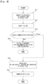
Figure 5 is a flowchart showing a control for determining filling method during filling in the first embodiment; -
Figure 6 is an explanation drawing of a hydrogen filling system according to the second embodiment of the preset invention; and -
Figure 7 is an explanation drawing of a hydrogen filling system according to the third embodiment of the preset invention. - Next, embodiments of the present invention will be explained with reference to the drawings. At first, the first embodiment of the present invention will be explained with reference to
Figs. 1 to 5 . InFig. 1 , a hydrogen filling system of the present invention whose overall construction is indicated withnumeral 100 includes ahydrogen filling device 1 and a control unit CU1 for controlling hydrogen filling, and the control unit CU1 is installed in thehydrogen filling device 1. To thehydrogen filling device 1 is connected afilling hose 2, and to an end of thefilling hose 2 is attached a filling nozzle 3. The filling nozzle 3 is connectable and disconnectable to a receptacle SR on an in-vehicle tank IT (fuel tank) of a vehicle S to which hydrogen is filled (for instance, a fuel cell vehicle FCV). In addition, thehydrogen filling device 1 includes a signal transmitting system 4 for transmitting information on the in-vehicle tank of the S such as pressure and temperature data. The signal transmitting system 4 connects thehydrogen filling device 1 and anoptical communication receiver 3A mounted to the filling nozzle 3 with each other. - During hydrogen filling, hydrogen is filled from the
hydrogen filling device 1 through thefilling hose 2 and the filling nozzle 3 to the in-vehicle tank of the S. In case of communication filling, during filling operation, information on inside of the in-vehicle tank IT such as temperature and pressure are detected by a pressure sensor P, a temperature sensor T and so on, and they are transmitted to the control unit CU1 mounted to thehydrogen filling device 1 from an optical communication transmitter not shown on the vehicle side, which is built in the receptacle SR through theoptical communication receiver 3A for optical communication, which is built in the filling nozzle 3, and the signal transmitting system 4. The control unit CU1 controls communication filling from thehydrogen filling device 1 to the inside of the in-vehicle tank IT based on the information on the inside of the in-vehicle tank IT, which is transmitted through the signal transmitting system 4, such as temperature and pressure. However, the communication from the in-vehicle tank IT to thehydrogen filling device 1 is not limited to optical communication but it is possible to use radio wave in a bandwidth that is used in an electronic toll collection system (ETC) for instance. Here in the hydrogen filling device 1 (hydrogen filling system 100), in place of the communication filling, non-communication filling can be used. - The control unit CU1 has functions of acquiring, in addition to the information on the inside of the in-vehicle tank IT such as temperature and pressure, inspection code for detecting appropriateness of the communication from the vehicle S side and judging whether or not vehicle communication is established. In addition, the control unit CU1 has a function of judging, during communication filling, the communication filling should be continued or stopped to convert to non-communication filling. In case of non-communication filling in which information on the in-vehicle tank IT of the vehicle S such as pressure and temperature are not transmitted to the
hydrogen filling device 1, in comparison to communication filling, hydrogen filling rate in the in-vehicle tank IT is set to be low. This is because, in case of non-communication filling, hydrogen is filled under the condition that status such as pressure and temperature in the in-vehicle tank IT of the vehicle S to which hydrogen is filled is not unknown, it is more dangerous in comparison to communication filling, so that hydrogen is filled in a less dangerous way (in a safer direction). In this connection, in case of non-communication filling, hydrogen is not filled up to the limit of the in-vehicle tank IT with high pressure, that is, full tank. The control unit CU1 according to the first embodiment will be explained with reference toFigs. 2 to 5 . - In
Fig. 2 showing functional blocks of the control unit CU1, the control unit CU1 includes a communication filling establishment decision block 1A, an abnormality decision block 1B and a fillingmethod decision block 1C. The communication filling establishment decision block 1A acquires, before starting hydrogen filling, from the pressure sensor P, temperature sensor T and others in the in-vehicle tank IT (refer toFig. 1 ) of the vehicle S, pressure data, temperature data and so on for each control cycle through the signal line SL1 and acquires inspection code from the inspection code transmitter K of the vehicle through the signal line SL2. The communication filling establishment decision block 1A has a function of judging, based on the acquired inspection data, pressure data, temperature data and so on, whether or not communication of transmitting data such as pressure and temperature on the vehicle S side (in the in-vehicle tank IT), that is, vehicle communication, is established. Here, that the vehicle communication is established is a precondition for communication filling. - The result of the judgement by the communication filling establishment decision block 1A, that is, whether vehicle communication is established or not, is transmitted to the filling
method decision block 1C through the signal line SL3, and to the abnormality discrimination block 1B through the signal line SL4. Meanwhile, it is conventionally performed to judge establishment of the vehicle communication (or soundness of communication itself) by checking whether or not data transmitted from a vehicle side such as pressure and temperature are valid. - In the judgement whether or not vehicle communication is established, when valid data are continuously received from the vehicle S side (the pressure sensor P, the temperature sensor T in the in-vehicle tank IT) over predetermined intervals (for example 500msec), it is judged to be "vehicle communication is established". In other words, even when invalid data are temporarily sent from the vehicle S side (the pressure sensor P, the temperature sensor T in the in-vehicle tank IT) at a predetermined interval (for example 500msec), it is not immediately judged to be "vehicle communication is not established". On the other hand, when invalid data are continuously sent from the vehicle S side over predetermined intervals (for example 500msec) or signals from the vehicle S are stopped, it is judged to be "vehicle communication is not established".
- The abnormality discrimination block 1B has functions of acquiring, during communication filling, from the pressure sensor P, temperature sensor T and others in the in-vehicle tank IT, pressure data, temperature data and so on through the signal line SL5 and acquiring the judgement result, that is, whether vehicle communication is established or not through the signal line SL4. Further, the abnormality discrimination block 1B has a function of judging whether or not the obtained pressure data, temperature data and so on are abnormal. Standard of abnormality judgment and work procedure in the abnormality discrimination block 1B are explained with reference to
Figs. 3 and5 in detail. The result of judgement (whether or not the obtained pressure data, temperature data and so on are abnormal) is transmitted to the filling method decision block 1C through the signal line SL6. - The filling
method decision block 1C has functions of acquiring judgment result (whether or not vehicle communication is established) of the communication filling establishment decision block 1A through the signal line SL3 and determining communication filling or non-communication filling. The fillingmethod decision block 1C selects communication filling when vehicle communication is established before filling starts, and selects non-communication filling when vehicle communication is not established. In addition, the fillingmethod decision block 1C has a function of acquiring judgement result (whether or not there is an abnormality in pressure data, temperature data and so on during communication filling) through the signal line SL6. Then, the fillingmethod decision block 1C has a function of determining whether communication filling as a filling method is continuously performed or the communication filling is stopped to convert to non-communication filling. The fillingmethod decision block 1C selects continuously performing communication filling when there is no abnormality in pressure data, temperature data and so on during communication filling, and selects stopping the communication filling and converting to non-communication filling when there is an abnormality in pressure data, temperature data and so on. - The judgement result of the filling
method decision block 1C is transmitted to a filling method switching means 5 of thehydrogen filling device 1 through the signal line SL7. The filling method switching means 5 selects, based on the determination result of the fillingmethod decision block 1C, filling method. Then, communication filling or non-communication filling is selected, or communication filling is stopped and converted to non-communication filling. Here, operation of converting communication filling to non-communication filling can be carried out by processing with software. - In
Fig. 3 showing each functional block in the abnormality discrimination block 1B shown inFig. 2 in detail, the abnormality discrimination block 1B includes a branching block 1D, a delay block 1E, a comparison block 1F and a decision block 1G. The branching block 1D has functions of acquiring, from the pressure sensor P, temperature sensor T and others in the in-vehicle tank IT, pressure data, temperature data and so on for each control cycle during communication filling through the signal line SL5 and transmitting the acquired pressure data, temperature data and so on for each control cycle to the comparison block 1F though the signal line SL9. Further, the branching block 1D has a function of transmitting the pressure data, the temperature data and so on for each control cycle to the delay block 1E through the signal line SL10. - The delay block 1E has functions of delaying pressure data, temperature data and others obtained from the branching block 1D for each operation cycle by one operation cycle, and transmitting the delayed data to the comparison block 1F through the signal line SL11. Here, among the pressure data, temperature data and so on that are transmitted from the delay block 1E to the comparison block 1F, the pressure data and temperature data that are transmitted from the branching block 1D to the comparison block 1F and the delay block 1E are indicated to be symbols P(n) and T(n). Then, pressure data and temperature data that are delayed by one control cycle against the pressure data P(n) and the temperature data T(n) by the delay block 1E are indicated to be P(n-1) and T(n-1) respectively. For example, data transmitted from the branching block 1D to the comparison block 1F and the delay block 1E are P(n) and T(n), and data transmitted from the delay block 1E to the comparison block 1F and before the P(n) and the T(n) by one control cycle are P(n-1) and T(n-1).
- The comparison block 1F has functions of comparing pressure data P(n) and temperature data T(n) obtained from the branching block 1D and pressure data P(n-1) and temperature data T(n-1) obtained from the delay block 1E with each other, and calculating their differences ΔP and ΔT. Here, the differences ΔP and ΔT are shown with the following formulas.

- Results of the comparison by the comparison block 1F, that is, the differences ΔP and ΔT are sent to the decision block 1G through the signal line SL12.
- The decision block 1G has a function of judging whether there is an abnormality in pressure or temperature data in the in-vehicle tank IT at communication filling based on the comparison result (the differences ΔP, ΔT). In the judgement, the decision block 1G judges a condition that pressure and temperature data in the in-vehicle tank IT at communication filling gradually increase as normal. Specifically, comparing the pressure and temperature data P(n) and T(n) with precedent (one control cycle before) pressure and temperature data P(n-1) and T(n-1), the decision block 1G judges that it is normal when increased amounts are within predetermined values δ1, δ2 (δ1, δ2 are positive values). Conditions that the decision block 1G judges as normal are shown below.

- On the other hand, comparing the pressure and temperature data P(n) and T(n) with precedent (one control cycle before) pressure and temperature data P(n-1) and T(n-1), the decision block 1G judges that it is abnormal when increased amounts are larger than predetermined values δ1, δ2 (rapidly increased) or the increased amounts are negative values (pressure or temperature is decreased). Conditions that the decision block 1G judges as abnormal are shown below.


- The judgement result of the decision block 1G (whether or not there is an abnormality in pressure or temperature data) is transmitted to the filling method decision block 1C (refer to
Fig. 2 ) through the signal line SL6. The judgement whether or not there is an abnormality in pressure or temperature data by the decision block 1G is carried out at different intervals from those (for instance 500msec) in the judgement of vehicle communication establishment. For example, when pressure, temperature or the like is abnormal over longer intervals than the intervals (for instance 500msec) in the judgement of vehicle communication establishment, it is judged as abnormal. Here, in case that control cycle is 100msec, when five consecutive abnormalities of pressure, temperature or the like occur for instance, it is judged as abnormal. However, the five times (or 500msec) is mere example, the times may not be five (the predetermined interval may not be 500msec). - Next, in the first embodiment, control in initial stage of hydrogen filling will be explained mainly with reference to
Fig. 4 . InFig. 4 , in Step S1, the filling nozzle 3 (refer toFig. 1 ) of thehydrogen filling device 1 is connected to the receptacle SR (refer toFig. 1 ) on the in-vehicle tank IT side of the vehicle S (fuel cell vehicle, FCV). Then, in Step S2, command signal for starting filling from thehydrogen filling device 1 to the in-vehicle tank IT is transmitted. With this, hydrogen is filled in the in-vehicle tank. Receiving the command signal, the communication filling establishment decision block 1A judges whether or not vehicle communication between the vehicle S (in-vehicle tank IT) and thehydrogen filling device 1 is established (Step S3). In Step S3, in case that the vehicle communication is established (Step S3; Yes), the process proceeds to Step S4, and in case that the vehicle communication is not established (Step S3; No), the process proceeds to Step S6. - In Step S4 (vehicle communication is established), the filling
method decision block 1C determines that communication filling is performed. Then, data on the capacity of the in-vehicle tank IT is obtained from the vehicle S side, and pressure data, temperature data and so on in the in-vehicle tank IT are acquired to carry out communication filling. On the other hand, in Step S6 (vehicle communication is not established), the fillingmethod decision block 1C determines that non-communication filling is performed. Then, non-communication filling is carried out when hydrogen filling is started. - Next, in the first embodiment, control for converting to non-communication filling when an abnormality is detected during communication filling will be explained mainly with reference to
Fig. 5 . In Step S11 inFig. 5 , it is judged whether or not vehicle communication between the vehicle S (in-vehicle tank IT) and thehydrogen filling device 1 is established. The judgement in Step S11 is also, as described above with reference toFig. 2 , carried out by the communication filling establishment decision block 1A, it is judged to be "vehicle communication is established" when valid data are continuously received from the vehicle S side (the pressure sensor P, the temperature sensor T and others in the in-vehicle tank IT) over predetermined intervals (for example 500msec). In Step S11, in case that the vehicle communication is established (Step S11; Yes), the process proceeds to Step S12, and in case that the vehicle communication is not established (Step S11; No), the process proceeds to Step S13. - In Step S12 (vehicle communication is established), the filling
method decision block 1C selects communication filling, and uninterruptedly acquires pressure data, temperature data and others in the in-vehicle tank IT to continue communication filling. Then, the process proceeds to Step S14. On the other hand, in Step S13 (vehicle communication is not established), the fillingmethod decision block 1C selects non-communication filling, and stops communication filling to convert to non-communication filling. And, hydrogen filling by non-communication filling continues. - In Step S14 (communication filling continues), it is judged whether or not pressure data obtained from the pressure sensor P in the in-vehicle tank IT is lower than a threshold value of pressure (for example 87.5 MPa), and temperature data obtained from the temperature sensor T is lower than a threshold value of temperature (for example 85°C). The threshold value of pressure (for example 87.5 MPa) and the threshold value of temperature (for example 85°C) for maintaining inside of the in-vehicle tank IT safe are determined based on a standard of hydrogen filling in Japan. Meanwhile, to the judgements whether or not the pressure and the temperature are lower than the safe threshold values can be applied conventionally known technique, so that they are omitted in the functional block diagrams in
Figs. 2 and 3 . On the judgement in Step S14, when the pressure in the in-vehicle tank IT is lower than the threshold value of pressure, and the temperature in the in-vehicle tank IT is lower than the threshold value of temperature (Step S14; Yes), the process proceeds to Step S16. On the other hand, when the pressure in the in-vehicle tank IT is equal to or higher than the threshold value of pressure, or the temperature in the in-vehicle tank IT is equal to or higher than the threshold value of temperature (Step S14; No), the process proceeds to Step S15. In Step S15 (in case that the pressure in the in-vehicle tank IT is equal to or higher than the threshold value of pressure or the temperature in the in-vehicle tank IT is equal to or higher than the threshold value of temperature), it is judged that safety hydrogen filling is not carried out, and the hydrogen filling is stopped. - In Step S16 (pressure in the in-vehicle tank IT is lower than the threshold value of pressure, and temperature in the in-vehicle tank IT is lower than the threshold value of temperature), it is judged whether there is an abnormality in pressure or temperature data in the in-vehicle tank IT during communication filling or not. This judgement is, as stated with reference to
Figs. 2 and 3 in detail), performed by the abnormality discrimination block 1B of control unit CU1, condition that the pressure and temperature data gradually increase is judged to be normal (no abnormality). As described above, when P(n), T(n) are pressure data and temperature data in the control cycle, P(n-1), T(n-1) are pressure data and temperature data in the precedent (one control cycle before) control cycle, and δ1, δ2 are positive values, in case that no abnormality exists in the pressure and temperature data, following formulas are established.
- In case that the above formulas are not established, the abnormality discrimination block 1B judges abnormality. On the judgement in Step S16, when no abnormality exists in the pressure data, the temperature data and so on in the in-vehicle tank IT (Step S16; Yes), the process proceeds to Step S17, and when an abnormality exists in the pressure data, the temperature data or others in the in-vehicle tank IT (Step S16; No), the process proceeds to Step S13.
- In Step S17 (no abnormality in the pressure data, the temperature data and so on in the in-vehicle tank IT), communication filling continues, and the process returns to Step S11. On the other hand, in Step S13 (abnormality in the pressure data, the temperature data and so on in the in-vehicle tank IT), the communication filling is stopped and is converted to the non-communication filling, and hydrogen is filled with non-communication filling.
- In the
hydrogen filling system 100 shown inFigs. 1 to 5 according to the first embodiment, at the communication filling, when the pressure data, the temperature data or the like in the in-vehicle tank IT rapidly increases, or an increased amount is zero or negative value, it is judged to be abnormal, and communication filling is converted to non-communication filling. Then, in the non-communication filling, filling rate is set to be lower than that of the communication filling, so that hydrogen filling is carried out safely. In addition, it is prevented that hydrogen is filled up to the limit of the in-vehicle tank IT, that is, full tank. Therefore, even when during the communication filling, a circumstance that cannot accurately transmit the pressure data, the temperature data and so on in the in-vehicle tank IT to thehydrogen filling device 1 side, the communication filling is converted to non-communication filling, in which there is some space (safer) on the in-vehicle tank IT side, hydrogen is safely filled. In addition, before the communication filling starts, in case that communication filling, which transmits the pressure data, the temperature data and so on in the in-vehicle tank IT to thehydrogen filling device 1 side, is not established, the communication filling is avoided, and non-communication filling can be selected. - Next, with reference to
Fig. 6 , the second embodiment of the present invention will be explained. In the hydrogen filling system 100-1 shown inFig. 6 , the control unit CU2 is mounted, not to eachhydrogen filling device 1, but to arear equipment 10. Here, the "rear equipment" includes so-called "POS" also in this specification. And, the rear equipment is mounted in an office for instance in a gas station. InFig. 6 , therear equipment 10 is installed in an office of a gas station with plurality of hydrogen filling devices (dispensers) 1, and the control unit CU2 is mounted in therear equipment 10. The control unit CU2 of therear equipment 10 is connected to a plurality (three inFig. 6 ) ofhydrogen filling devices 1, 1-1, 1-2 throughsignal transmitting systems 11, 11-1, 11-2 capable of bidirectional communication such as optical communication path, and eachhydrogen filling devices 1, 1-1, 1-2 is connectable to each in-vehicle tank IT, IT-1, IT-2 of each vehicle S, S-1, S-2 through a filling hose and a filling nozzle. - The control unit CU2 of the
rear equipment 10 has the same function as the control unit CU1 of the first embodiment, and information on pressure, temperature and others of the in-vehicle-tanks IT, IT-1, IT-2 of the vehicles S, S-1, S-2 are transmitted to the control unit CU2 of therear equipment 10 through the signal transmitting systems 4, 4-1, 4-2 on thehydrogen filling device 1 side and thesignal transmitting systems 11, 11-1, 11-2 on therear equipment 10 side. Together with the information, control signals from the control unit CU2 are sent to eachhydrogen filling device 1, 1-1, 1-2. With this, communication filling can be performed by thehydrogen filling device 1, 1-1, 1-2 to each vehicle S, S-1, S-2. Other constructions and action effects in the second embodiment shown inFig. 6 are the same as those of the first embodiment shown inFigs. 1 to 5 . - In a hydrogen filling system 100-2 according to the third embodiment shown in
Fig. 7 , a plurality of (three for example) rear equipment are connected to a cloud computer CU3 in bidirectionally communicable way through internets or otherinformation communication networks 12, 12-1, 12-2. Then, the cloud computer CU3 has the same functions as those of the control units CU1, CU2 of the first and second embodiments. Each of therear equipment 10, 10-1, 10-2, which is connected to the cloud computer CU3, of each hydrogen filling equipment is connected to plurality of or each hydrogen filling device in bidirectionally communicable way throughsignal transmitting systems 11, 11-1, 11-2. Then, eachhydrogen filling device 1, 1-1, 1-2 is connectable to an in-vehicle tank of a vehicle not shown to which hydrogen is filled. InFig. 7 , each of therear equipment 10, 10-1, 10-2 of each hydrogen filling facility has a singlehydrogen filling device 1, 1-1, 1-2. - Information on pressure, temperature and others of an in-vehicle tank of a vehicle not shown connected to the
hydrogen filling device 1, 1-1, 1-2 of each hydrogen filling facility is sent to the cloud computer CU3 through thehydrogen filling devices 1, 1-1, 1-2 and therear equipments 10, 10-1, 10-2, and control signals from the cloud computer CU3 are sent to thehydrogen filling devices 1, 1-1, 1-2 through therear equipments 10, 10-1, 10-2. With this, communication filling can be done from thehydrogen filling devices 1, 1-1, 1-2 to vehicles. In this connection, although illustration is omitted inFig. 7 , the cloud computer CU3 can be connected not only to therear equipments 10, 10-1, 10-2, but also to thehydrogen filling devices 1, 1-1, 1-2 in bidirectionally communicable way. Other constructions and action effects of the third embodiment shown inFig. 7 are the same as those of the first embodiment shown inFigs. 1 to 5 and the second embodiment shown inFig. 6 . - The embodiments shown in the drawings are mere examples, and technical scope of the present invention in not limited to those.
-
- 1 hydrogen filling device
- 100, 100-1, 100-2 hydrogen filling systems
- CU1, CU2, CU3 control units (cloud computer)
- IT in-vehicle tank
- S vehicle (fuel cell vehicle, FCV)
- δ1, δ2 predetermined values (positive values)
Claims (4)
- A hydrogen filling system (100) comprising a control unit (CU, CU1, CU2) for controlling hydrogen filling, wherein said control unit (CU, CU1, CU2) has a function of judging whether or not there is an abnormality in pressure or temperature data in an in-vehicle tank (IT) at communication filling and a function of stopping the communication filling and converting to non-communication filling when there is an abnormality in the pressure or the temperature data, wherein said control unit (CU, CU1, CU2) has a function of comparing the pressure or temperature data with precedent pressure or temperature data and judging as normal when increased amount of the pressure data or the temperature data is within a predetermined value, and as abnormal when the increased amount of the pressure data or the temperature data is larger than the predetermined value; zero; or negative, wherein a filling rate is in the non-communication filling set to be lower than that of the communication filling.
- The hydrogen filling system (100) as claimed in claim 1, wherein said control unit (CU, CU1, CU2) has functions of judging whether or not, before starting the communication filling, communication for transmitting data on the pressure and the temperature in the in-vehicle tank (IT) to a filling device is established, and selecting the communication filling when the communication is established and selecting the non-communication filling when the communication is not established.
- A hydrogen filling method comprising a process for judging whether or not there is an abnormality in pressure or temperature data in an in-vehicle tank (IT) at communication filling and a process for stopping communication filling and converting to non-communication filling when there is an abnormality in the pressure or the temperature data, wherein in said judging process the pressure or temperature data is compared with precedent pressure or temperature data and it is judged as normal when increased amount of the pressure data or the temperature data is within a predetermined value, and as abnormal when the increased amount of the pressure data or the temperature data is larger than the predetermined value; zero; or negative, wherein a filling rate is in the non-communication filling set to be lower than that of the communication filling.
- The hydrogen filling method as claimed in claim 3 further comprising a process for judging whether or not, before starting the communication filling, communication for transmitting data on the pressure and the temperature in the in-vehicle tank to a filling device is established, and a process for selecting the communication filling when the communication is established and selecting the non-communication filling when the communication is not established.
Applications Claiming Priority (1)
| Application Number | Priority Date | Filing Date | Title |
|---|---|---|---|
| JP2019004878A JP6737350B2 (en) | 2019-01-16 | 2019-01-16 | Hydrogen filling system and hydrogen filling method |
Publications (2)
| Publication Number | Publication Date |
|---|---|
| EP3683490A1 EP3683490A1 (en) | 2020-07-22 |
| EP3683490B1 true EP3683490B1 (en) | 2023-03-08 |
Family
ID=69157638
Family Applications (1)
| Application Number | Title | Priority Date | Filing Date |
|---|---|---|---|
| EP20151037.7A Active EP3683490B1 (en) | 2019-01-16 | 2020-01-09 | Hydrogen filling system and hydrogen filling method |
Country Status (5)
| Country | Link |
|---|---|
| US (1) | US11370651B2 (en) |
| EP (1) | EP3683490B1 (en) |
| JP (1) | JP6737350B2 (en) |
| KR (1) | KR102286862B1 (en) |
| CN (1) | CN111442185B (en) |
Families Citing this family (20)
| Publication number | Priority date | Publication date | Assignee | Title |
|---|---|---|---|---|
| US11649927B2 (en) * | 2020-01-30 | 2023-05-16 | Toyota Motor Engineering & Manufacturing North America, Inc. | Dual-inlet valve refilling of a single fuel cylinder |
| CN111993910B (en) * | 2020-09-02 | 2022-09-23 | 江苏集萃安泰创明先进能源材料研究院有限公司 | Hydrogen fuel cell assisted bicycle control system and control method thereof |
| WO2022108257A1 (en) * | 2020-11-17 | 2022-05-27 | (주)미래기준연구소 | Method for controlling real-time response hydrogen fueling, and device therefor |
| KR102489660B1 (en) * | 2021-02-22 | 2023-01-17 | 주식회사 현대케피코 | System and method for charger diagnosing of electric vehicle |
| KR102405399B1 (en) | 2021-06-02 | 2022-06-07 | (주)세양메카트로닉스 | Method And Apparatus For Defrosting For Hydrogen Charging Gun |
| US11598485B2 (en) * | 2021-07-20 | 2023-03-07 | FirstElement Fuel, Inc. | LH2 offloading with auto-purge and pre-cooling |
| DE102021209795A1 (en) * | 2021-09-06 | 2023-03-09 | Hyundai Motor Company | Alternative fuel vehicle refueling adapter and refueling method |
| JP7582926B2 (en) * | 2021-10-18 | 2024-11-13 | 本田技研工業株式会社 | Method for controlling hydrogen filling device and hydrogen filling device |
| DE102021211719A1 (en) * | 2021-10-18 | 2023-04-20 | Robert Bosch Gesellschaft mit beschränkter Haftung | Method and device for refueling a motor vehicle at a hydrogen refueling station |
| KR20230131335A (en) | 2022-03-03 | 2023-09-13 | 현대자동차주식회사 | Hydrogen storage system and method for controlling the same |
| CN114801896B (en) * | 2022-05-31 | 2024-08-20 | 重庆长安新能源汽车科技有限公司 | Hydrogenation control method for fuel cell automobile, FCCU controller and automobile |
| KR102709655B1 (en) | 2022-05-31 | 2024-09-25 | 주식회사 티티엑스 | System and method for self-refueling of hydrogen |
| WO2024102662A1 (en) * | 2022-11-08 | 2024-05-16 | Nikola Corporation | Systems and methods for monitoring hydrogen fuel |
| JP7620892B2 (en) | 2023-01-18 | 2025-01-24 | 株式会社タツノ | Fuel supply device and fuel supply method |
| JP7612951B2 (en) * | 2023-01-24 | 2025-01-15 | 株式会社タツノ | Calibration Equipment |
| KR20240136879A (en) * | 2023-03-07 | 2024-09-19 | 현대자동차주식회사 | Communication method and apparatus for hydrogen fueling handling error and emergency therefor |
| CN121693433A (en) | 2023-08-24 | 2026-03-17 | 东日本旅客铁道株式会社 | Hydrogen filling monitoring system and hydrogen filling method |
| WO2025150977A1 (en) * | 2024-01-12 | 2025-07-17 | 현대자동차주식회사 | Hydrogen fueling method optimized using predicted time cycle control of artificial neural network model and controller for same |
| US20250314353A1 (en) * | 2024-04-09 | 2025-10-09 | Caterpillar Inc. | Hydrogen defuel system for hydrogen tanks |
| CN120048941B (en) * | 2025-04-23 | 2025-07-04 | 北京星驰蓝氢科技有限公司 | A vehicle-mounted hydrogen system replacement method and system based on safe organic liquid |
Family Cites Families (23)
| Publication number | Priority date | Publication date | Assignee | Title |
|---|---|---|---|---|
| JP4056646B2 (en) | 1998-12-11 | 2008-03-05 | ホーユー株式会社 | Hair comb |
| KR100962896B1 (en) * | 2008-04-14 | 2010-06-10 | 현대자동차주식회사 | Hydrogen Safety Filling Methods for Hydrogen Storage Systems |
| JP5257206B2 (en) * | 2009-03-31 | 2013-08-07 | 株式会社デンソー | Fluid filling system, moving body, and supply equipment |
| JP5332933B2 (en) * | 2009-06-17 | 2013-11-06 | トヨタ自動車株式会社 | Hydrogen filling system |
| NO332687B1 (en) * | 2009-10-21 | 2012-12-10 | Nel Hydrogen As | Procedure for operation and control of gas filling |
| JP5489752B2 (en) * | 2010-01-29 | 2014-05-14 | トヨタ自動車株式会社 | Gas filling system and vehicle |
| JP5271389B2 (en) * | 2011-07-05 | 2013-08-21 | 本田技研工業株式会社 | Fuel gas utilization device |
| JP5591854B2 (en) * | 2012-03-19 | 2014-09-17 | 本田技研工業株式会社 | Mobile body and fuel filling system thereof |
| JP2013200019A (en) * | 2012-03-26 | 2013-10-03 | Honda Motor Co Ltd | Fuel gas filling method |
| JP6001315B2 (en) * | 2012-04-26 | 2016-10-05 | トヨタ自動車株式会社 | Gas filling system and vehicle |
| WO2014124102A1 (en) * | 2013-02-07 | 2014-08-14 | Canadian Standards Association Group | Hydrogen dispenser test apparatus and method |
| JP5901608B2 (en) * | 2013-12-26 | 2016-04-13 | 本田技研工業株式会社 | Fuel filling system |
| JP6375684B2 (en) * | 2014-05-07 | 2018-08-22 | 日産自動車株式会社 | Control device, fuel gas filling system, and fuel gas filling method |
| JP6369163B2 (en) * | 2014-06-25 | 2018-08-08 | 日産自動車株式会社 | Fuel gas filling system and fuel gas filling method |
| JP6150839B2 (en) * | 2015-04-14 | 2017-06-21 | 本田技研工業株式会社 | Fuel filling system and fuel filling method thereof |
| US10077998B2 (en) * | 2015-09-14 | 2018-09-18 | Honda Motor Co., Ltd. | Hydrogen fueling with integrity checks |
| JP2017125515A (en) * | 2016-01-12 | 2017-07-20 | 株式会社デンソー | Remaining fuel gas calculation device |
| JP2017206038A (en) * | 2016-05-16 | 2017-11-24 | 株式会社デンソー | Transmitter diagnostic device |
| JP6786353B2 (en) * | 2016-10-31 | 2020-11-18 | Eneos株式会社 | Hydrogen fuel supply method of hydrogen station and hydrogen fuel supply system of hydrogen station |
| JP6548093B2 (en) | 2017-06-16 | 2019-07-24 | 株式会社タツノ | Hydrogen filling device |
| JP6738561B2 (en) * | 2017-06-21 | 2020-08-12 | 株式会社タツノ | Filling device |
| JP6984251B2 (en) * | 2017-09-07 | 2021-12-17 | トヨタ自動車株式会社 | Fuel cell vehicle |
| CN108775506A (en) * | 2018-03-16 | 2018-11-09 | 浙江昊凡科技有限公司 | A kind of method and system that hydrogenation stations hydrogen energy source quickly fills |
-
2019
- 2019-01-16 JP JP2019004878A patent/JP6737350B2/en active Active
-
2020
- 2020-01-06 US US16/734,843 patent/US11370651B2/en active Active
- 2020-01-09 EP EP20151037.7A patent/EP3683490B1/en active Active
- 2020-01-14 KR KR1020200004665A patent/KR102286862B1/en active Active
- 2020-01-15 CN CN202010043041.4A patent/CN111442185B/en active Active
Also Published As
| Publication number | Publication date |
|---|---|
| CN111442185A (en) | 2020-07-24 |
| US11370651B2 (en) | 2022-06-28 |
| JP6737350B2 (en) | 2020-08-05 |
| EP3683490A1 (en) | 2020-07-22 |
| US20200223684A1 (en) | 2020-07-16 |
| KR102286862B1 (en) | 2021-08-09 |
| CN111442185B (en) | 2023-05-05 |
| JP2020112242A (en) | 2020-07-27 |
| KR20200089227A (en) | 2020-07-24 |
Similar Documents
| Publication | Publication Date | Title |
|---|---|---|
| EP3683490B1 (en) | Hydrogen filling system and hydrogen filling method | |
| CN108632347B (en) | Method of detecting vehicle collision at vehicle and vehicle telematics apparatus | |
| US9403663B2 (en) | Managing remote control of an elevator system | |
| AU2020269717B2 (en) | Vehicle control system | |
| US20080223482A1 (en) | Safety Device to Prevent Overfilling | |
| US10396832B2 (en) | Filling apparatus | |
| CN109240313A (en) | Barrier-avoiding method, the apparatus and system of unmanned fork truck | |
| US11010989B2 (en) | Electronic device and processing method for electronic device | |
| JP2011122657A (en) | Fuel gas station, fuel gas filling system, and fuel gas filling method | |
| JP6548093B2 (en) | Hydrogen filling device | |
| KR102349704B1 (en) | System and method for diagnosing main controller abnormal operation | |
| JP2008546257A (en) | Vehicle performance data communication link | |
| EP2624637B1 (en) | Wireless communication apparatus and wireless communication system | |
| EP2601620A1 (en) | Freight evaluation for an aircraft | |
| US10131231B2 (en) | Vehicle power transmitting and receiving control device that performs abnormality determination of bidirectional communication | |
| CN105607615A (en) | Fault diagnosis system | |
| US20240185654A1 (en) | Tire temperature prediction system, tire temperature prediction program, and tire temperature prediction method | |
| EP3171202B1 (en) | System and method of sharing vehicle location information | |
| CN109189567B (en) | Time delay calculation method, device, equipment and computer readable storage medium | |
| CN113139666A (en) | Charging pile reservation method and device, charging pile management platform and automobile | |
| JP2017032005A (en) | Fuel gas charging system | |
| US20040010370A1 (en) | Stolen vehicle tracking system and stolen vehicle tracking method | |
| US20070115103A1 (en) | Remote sensor network system with redundancy | |
| KR102344211B1 (en) | System and method for diagnosing main controller abnormal operation | |
| EP3686145B1 (en) | Remotely maintaining the connection status of a connection port of a passenger carrying system |
Legal Events
| Date | Code | Title | Description |
|---|---|---|---|
| PUAI | Public reference made under article 153(3) epc to a published international application that has entered the european phase |
Free format text: ORIGINAL CODE: 0009012 |
|
| STAA | Information on the status of an ep patent application or granted ep patent |
Free format text: STATUS: THE APPLICATION HAS BEEN PUBLISHED |
|
| AK | Designated contracting states |
Kind code of ref document: A1 Designated state(s): AL AT BE BG CH CY CZ DE DK EE ES FI FR GB GR HR HU IE IS IT LI LT LU LV MC MK MT NL NO PL PT RO RS SE SI SK SM TR |
|
| AX | Request for extension of the european patent |
Extension state: BA ME |
|
| STAA | Information on the status of an ep patent application or granted ep patent |
Free format text: STATUS: REQUEST FOR EXAMINATION WAS MADE |
|
| 17P | Request for examination filed |
Effective date: 20210122 |
|
| RBV | Designated contracting states (corrected) |
Designated state(s): AL AT BE BG CH CY CZ DE DK EE ES FI FR GB GR HR HU IE IS IT LI LT LU LV MC MK MT NL NO PL PT RO RS SE SI SK SM TR |
|
| GRAP | Despatch of communication of intention to grant a patent |
Free format text: ORIGINAL CODE: EPIDOSNIGR1 |
|
| STAA | Information on the status of an ep patent application or granted ep patent |
Free format text: STATUS: GRANT OF PATENT IS INTENDED |
|
| INTG | Intention to grant announced |
Effective date: 20221208 |
|
| GRAS | Grant fee paid |
Free format text: ORIGINAL CODE: EPIDOSNIGR3 |
|
| GRAA | (expected) grant |
Free format text: ORIGINAL CODE: 0009210 |
|
| STAA | Information on the status of an ep patent application or granted ep patent |
Free format text: STATUS: THE PATENT HAS BEEN GRANTED |
|
| AK | Designated contracting states |
Kind code of ref document: B1 Designated state(s): AL AT BE BG CH CY CZ DE DK EE ES FI FR GB GR HR HU IE IS IT LI LT LU LV MC MK MT NL NO PL PT RO RS SE SI SK SM TR |
|
| REG | Reference to a national code |
Ref country code: CH Ref legal event code: EP Ref country code: AT Ref legal event code: REF Ref document number: 1552783 Country of ref document: AT Kind code of ref document: T Effective date: 20230315 |
|
| REG | Reference to a national code |
Ref country code: IE Ref legal event code: FG4D |
|
| REG | Reference to a national code |
Ref country code: DE Ref legal event code: R096 Ref document number: 602020008593 Country of ref document: DE |
|
| REG | Reference to a national code |
Ref country code: SE Ref legal event code: TRGR |
|
| REG | Reference to a national code |
Ref country code: NO Ref legal event code: T2 Effective date: 20230308 |
|
| REG | Reference to a national code |
Ref country code: LT Ref legal event code: MG9D |
|
| REG | Reference to a national code |
Ref country code: NL Ref legal event code: MP Effective date: 20230308 |
|
| PG25 | Lapsed in a contracting state [announced via postgrant information from national office to epo] |
Ref country code: RS Free format text: LAPSE BECAUSE OF FAILURE TO SUBMIT A TRANSLATION OF THE DESCRIPTION OR TO PAY THE FEE WITHIN THE PRESCRIBED TIME-LIMIT Effective date: 20230308 Ref country code: LV Free format text: LAPSE BECAUSE OF FAILURE TO SUBMIT A TRANSLATION OF THE DESCRIPTION OR TO PAY THE FEE WITHIN THE PRESCRIBED TIME-LIMIT Effective date: 20230308 Ref country code: LT Free format text: LAPSE BECAUSE OF FAILURE TO SUBMIT A TRANSLATION OF THE DESCRIPTION OR TO PAY THE FEE WITHIN THE PRESCRIBED TIME-LIMIT Effective date: 20230308 Ref country code: HR Free format text: LAPSE BECAUSE OF FAILURE TO SUBMIT A TRANSLATION OF THE DESCRIPTION OR TO PAY THE FEE WITHIN THE PRESCRIBED TIME-LIMIT Effective date: 20230308 Ref country code: ES Free format text: LAPSE BECAUSE OF FAILURE TO SUBMIT A TRANSLATION OF THE DESCRIPTION OR TO PAY THE FEE WITHIN THE PRESCRIBED TIME-LIMIT Effective date: 20230308 |
|
| REG | Reference to a national code |
Ref country code: AT Ref legal event code: MK05 Ref document number: 1552783 Country of ref document: AT Kind code of ref document: T Effective date: 20230308 |
|
| PG25 | Lapsed in a contracting state [announced via postgrant information from national office to epo] |
Ref country code: NL Free format text: LAPSE BECAUSE OF FAILURE TO SUBMIT A TRANSLATION OF THE DESCRIPTION OR TO PAY THE FEE WITHIN THE PRESCRIBED TIME-LIMIT Effective date: 20230308 Ref country code: GR Free format text: LAPSE BECAUSE OF FAILURE TO SUBMIT A TRANSLATION OF THE DESCRIPTION OR TO PAY THE FEE WITHIN THE PRESCRIBED TIME-LIMIT Effective date: 20230609 Ref country code: FI Free format text: LAPSE BECAUSE OF FAILURE TO SUBMIT A TRANSLATION OF THE DESCRIPTION OR TO PAY THE FEE WITHIN THE PRESCRIBED TIME-LIMIT Effective date: 20230308 |
|
| PG25 | Lapsed in a contracting state [announced via postgrant information from national office to epo] |
Ref country code: SM Free format text: LAPSE BECAUSE OF FAILURE TO SUBMIT A TRANSLATION OF THE DESCRIPTION OR TO PAY THE FEE WITHIN THE PRESCRIBED TIME-LIMIT Effective date: 20230308 Ref country code: RO Free format text: LAPSE BECAUSE OF FAILURE TO SUBMIT A TRANSLATION OF THE DESCRIPTION OR TO PAY THE FEE WITHIN THE PRESCRIBED TIME-LIMIT Effective date: 20230308 Ref country code: PT Free format text: LAPSE BECAUSE OF FAILURE TO SUBMIT A TRANSLATION OF THE DESCRIPTION OR TO PAY THE FEE WITHIN THE PRESCRIBED TIME-LIMIT Effective date: 20230710 Ref country code: EE Free format text: LAPSE BECAUSE OF FAILURE TO SUBMIT A TRANSLATION OF THE DESCRIPTION OR TO PAY THE FEE WITHIN THE PRESCRIBED TIME-LIMIT Effective date: 20230308 Ref country code: AT Free format text: LAPSE BECAUSE OF FAILURE TO SUBMIT A TRANSLATION OF THE DESCRIPTION OR TO PAY THE FEE WITHIN THE PRESCRIBED TIME-LIMIT Effective date: 20230308 |
|
| PG25 | Lapsed in a contracting state [announced via postgrant information from national office to epo] |
Ref country code: SK Free format text: LAPSE BECAUSE OF FAILURE TO SUBMIT A TRANSLATION OF THE DESCRIPTION OR TO PAY THE FEE WITHIN THE PRESCRIBED TIME-LIMIT Effective date: 20230308 Ref country code: PL Free format text: LAPSE BECAUSE OF FAILURE TO SUBMIT A TRANSLATION OF THE DESCRIPTION OR TO PAY THE FEE WITHIN THE PRESCRIBED TIME-LIMIT Effective date: 20230308 Ref country code: IS Free format text: LAPSE BECAUSE OF FAILURE TO SUBMIT A TRANSLATION OF THE DESCRIPTION OR TO PAY THE FEE WITHIN THE PRESCRIBED TIME-LIMIT Effective date: 20230708 |
|
| REG | Reference to a national code |
Ref country code: DE Ref legal event code: R097 Ref document number: 602020008593 Country of ref document: DE |
|
| PLBE | No opposition filed within time limit |
Free format text: ORIGINAL CODE: 0009261 |
|
| STAA | Information on the status of an ep patent application or granted ep patent |
Free format text: STATUS: NO OPPOSITION FILED WITHIN TIME LIMIT |
|
| PG25 | Lapsed in a contracting state [announced via postgrant information from national office to epo] |
Ref country code: SI Free format text: LAPSE BECAUSE OF FAILURE TO SUBMIT A TRANSLATION OF THE DESCRIPTION OR TO PAY THE FEE WITHIN THE PRESCRIBED TIME-LIMIT Effective date: 20230308 Ref country code: DK Free format text: LAPSE BECAUSE OF FAILURE TO SUBMIT A TRANSLATION OF THE DESCRIPTION OR TO PAY THE FEE WITHIN THE PRESCRIBED TIME-LIMIT Effective date: 20230308 |
|
| 26N | No opposition filed |
Effective date: 20231211 |
|
| PG25 | Lapsed in a contracting state [announced via postgrant information from national office to epo] |
Ref country code: MC Free format text: LAPSE BECAUSE OF FAILURE TO SUBMIT A TRANSLATION OF THE DESCRIPTION OR TO PAY THE FEE WITHIN THE PRESCRIBED TIME-LIMIT Effective date: 20230308 |
|
| PG25 | Lapsed in a contracting state [announced via postgrant information from national office to epo] |
Ref country code: MC Free format text: LAPSE BECAUSE OF FAILURE TO SUBMIT A TRANSLATION OF THE DESCRIPTION OR TO PAY THE FEE WITHIN THE PRESCRIBED TIME-LIMIT Effective date: 20230308 |
|
| PG25 | Lapsed in a contracting state [announced via postgrant information from national office to epo] |
Ref country code: LU Free format text: LAPSE BECAUSE OF NON-PAYMENT OF DUE FEES Effective date: 20240109 |
|
| PG25 | Lapsed in a contracting state [announced via postgrant information from national office to epo] |
Ref country code: LU Free format text: LAPSE BECAUSE OF NON-PAYMENT OF DUE FEES Effective date: 20240109 |
|
| PG25 | Lapsed in a contracting state [announced via postgrant information from national office to epo] |
Ref country code: BE Free format text: LAPSE BECAUSE OF NON-PAYMENT OF DUE FEES Effective date: 20240131 |
|
| PG25 | Lapsed in a contracting state [announced via postgrant information from national office to epo] |
Ref country code: BE Free format text: LAPSE BECAUSE OF NON-PAYMENT OF DUE FEES Effective date: 20240131 |
|
| REG | Reference to a national code |
Ref country code: BE Ref legal event code: MM Effective date: 20240131 |
|
| PG25 | Lapsed in a contracting state [announced via postgrant information from national office to epo] |
Ref country code: BG Free format text: LAPSE BECAUSE OF FAILURE TO SUBMIT A TRANSLATION OF THE DESCRIPTION OR TO PAY THE FEE WITHIN THE PRESCRIBED TIME-LIMIT Effective date: 20230308 |
|
| PG25 | Lapsed in a contracting state [announced via postgrant information from national office to epo] |
Ref country code: BG Free format text: LAPSE BECAUSE OF FAILURE TO SUBMIT A TRANSLATION OF THE DESCRIPTION OR TO PAY THE FEE WITHIN THE PRESCRIBED TIME-LIMIT Effective date: 20230308 |
|
| PG25 | Lapsed in a contracting state [announced via postgrant information from national office to epo] |
Ref country code: IE Free format text: LAPSE BECAUSE OF NON-PAYMENT OF DUE FEES Effective date: 20240109 |
|
| PG25 | Lapsed in a contracting state [announced via postgrant information from national office to epo] |
Ref country code: IE Free format text: LAPSE BECAUSE OF NON-PAYMENT OF DUE FEES Effective date: 20240109 |
|
| PGFP | Annual fee paid to national office [announced via postgrant information from national office to epo] |
Ref country code: DE Payment date: 20250130 Year of fee payment: 6 |
|
| PGFP | Annual fee paid to national office [announced via postgrant information from national office to epo] |
Ref country code: SE Payment date: 20250121 Year of fee payment: 6 |
|
| PGFP | Annual fee paid to national office [announced via postgrant information from national office to epo] |
Ref country code: NO Payment date: 20250124 Year of fee payment: 6 |
|
| PGFP | Annual fee paid to national office [announced via postgrant information from national office to epo] |
Ref country code: CH Payment date: 20250201 Year of fee payment: 6 |
|
| PGFP | Annual fee paid to national office [announced via postgrant information from national office to epo] |
Ref country code: FR Payment date: 20250127 Year of fee payment: 6 Ref country code: CZ Payment date: 20241231 Year of fee payment: 6 |
|
| PGFP | Annual fee paid to national office [announced via postgrant information from national office to epo] |
Ref country code: GB Payment date: 20250128 Year of fee payment: 6 Ref country code: IT Payment date: 20250129 Year of fee payment: 6 |
|
| PG25 | Lapsed in a contracting state [announced via postgrant information from national office to epo] |
Ref country code: CY Free format text: LAPSE BECAUSE OF FAILURE TO SUBMIT A TRANSLATION OF THE DESCRIPTION OR TO PAY THE FEE WITHIN THE PRESCRIBED TIME-LIMIT; INVALID AB INITIO Effective date: 20200109 |
|
| PG25 | Lapsed in a contracting state [announced via postgrant information from national office to epo] |
Ref country code: HU Free format text: LAPSE BECAUSE OF FAILURE TO SUBMIT A TRANSLATION OF THE DESCRIPTION OR TO PAY THE FEE WITHIN THE PRESCRIBED TIME-LIMIT; INVALID AB INITIO Effective date: 20200109 |
|
| PG25 | Lapsed in a contracting state [announced via postgrant information from national office to epo] |
Ref country code: TR Free format text: LAPSE BECAUSE OF FAILURE TO SUBMIT A TRANSLATION OF THE DESCRIPTION OR TO PAY THE FEE WITHIN THE PRESCRIBED TIME-LIMIT Effective date: 20230308 |