JP5901608B2 - Fuel filling system - Google Patents
Fuel filling system Download PDFInfo
- Publication number
- JP5901608B2 JP5901608B2 JP2013269736A JP2013269736A JP5901608B2 JP 5901608 B2 JP5901608 B2 JP 5901608B2 JP 2013269736 A JP2013269736 A JP 2013269736A JP 2013269736 A JP2013269736 A JP 2013269736A JP 5901608 B2 JP5901608 B2 JP 5901608B2
- Authority
- JP
- Japan
- Prior art keywords
- filling
- fuel
- value
- tank
- hydrogen
- Prior art date
- Legal status (The legal status is an assumption and is not a legal conclusion. Google has not performed a legal analysis and makes no representation as to the accuracy of the status listed.)
- Active
Links
Images


Classifications
-
- F—MECHANICAL ENGINEERING; LIGHTING; HEATING; WEAPONS; BLASTING
- F17—STORING OR DISTRIBUTING GASES OR LIQUIDS
- F17C—VESSELS FOR CONTAINING OR STORING COMPRESSED, LIQUEFIED OR SOLIDIFIED GASES; FIXED-CAPACITY GAS-HOLDERS; FILLING VESSELS WITH, OR DISCHARGING FROM VESSELS, COMPRESSED, LIQUEFIED, OR SOLIDIFIED GASES
- F17C5/00—Methods or apparatus for filling containers with liquefied, solidified, or compressed gases under pressures
- F17C5/06—Methods or apparatus for filling containers with liquefied, solidified, or compressed gases under pressures for filling with compressed gases
-
- F—MECHANICAL ENGINEERING; LIGHTING; HEATING; WEAPONS; BLASTING
- F17—STORING OR DISTRIBUTING GASES OR LIQUIDS
- F17C—VESSELS FOR CONTAINING OR STORING COMPRESSED, LIQUEFIED OR SOLIDIFIED GASES; FIXED-CAPACITY GAS-HOLDERS; FILLING VESSELS WITH, OR DISCHARGING FROM VESSELS, COMPRESSED, LIQUEFIED, OR SOLIDIFIED GASES
- F17C13/00—Details of vessels or of the filling or discharging of vessels
- F17C13/02—Special adaptations of indicating, measuring, or monitoring equipment
- F17C13/026—Special adaptations of indicating, measuring, or monitoring equipment having the temperature as the parameter
-
- F—MECHANICAL ENGINEERING; LIGHTING; HEATING; WEAPONS; BLASTING
- F17—STORING OR DISTRIBUTING GASES OR LIQUIDS
- F17C—VESSELS FOR CONTAINING OR STORING COMPRESSED, LIQUEFIED OR SOLIDIFIED GASES; FIXED-CAPACITY GAS-HOLDERS; FILLING VESSELS WITH, OR DISCHARGING FROM VESSELS, COMPRESSED, LIQUEFIED, OR SOLIDIFIED GASES
- F17C13/00—Details of vessels or of the filling or discharging of vessels
- F17C13/02—Special adaptations of indicating, measuring, or monitoring equipment
- F17C13/028—Special adaptations of indicating, measuring, or monitoring equipment having the volume as the parameter
-
- F—MECHANICAL ENGINEERING; LIGHTING; HEATING; WEAPONS; BLASTING
- F17—STORING OR DISTRIBUTING GASES OR LIQUIDS
- F17C—VESSELS FOR CONTAINING OR STORING COMPRESSED, LIQUEFIED OR SOLIDIFIED GASES; FIXED-CAPACITY GAS-HOLDERS; FILLING VESSELS WITH, OR DISCHARGING FROM VESSELS, COMPRESSED, LIQUEFIED, OR SOLIDIFIED GASES
- F17C2203/00—Vessel construction, in particular walls or details thereof
- F17C2203/06—Materials for walls or layers thereof; Properties or structures of walls or their materials
- F17C2203/0602—Wall structures; Special features thereof
- F17C2203/0604—Liners
-
- F—MECHANICAL ENGINEERING; LIGHTING; HEATING; WEAPONS; BLASTING
- F17—STORING OR DISTRIBUTING GASES OR LIQUIDS
- F17C—VESSELS FOR CONTAINING OR STORING COMPRESSED, LIQUEFIED OR SOLIDIFIED GASES; FIXED-CAPACITY GAS-HOLDERS; FILLING VESSELS WITH, OR DISCHARGING FROM VESSELS, COMPRESSED, LIQUEFIED, OR SOLIDIFIED GASES
- F17C2203/00—Vessel construction, in particular walls or details thereof
- F17C2203/06—Materials for walls or layers thereof; Properties or structures of walls or their materials
- F17C2203/0634—Materials for walls or layers thereof
- F17C2203/0636—Metals
- F17C2203/0646—Aluminium
-
- F—MECHANICAL ENGINEERING; LIGHTING; HEATING; WEAPONS; BLASTING
- F17—STORING OR DISTRIBUTING GASES OR LIQUIDS
- F17C—VESSELS FOR CONTAINING OR STORING COMPRESSED, LIQUEFIED OR SOLIDIFIED GASES; FIXED-CAPACITY GAS-HOLDERS; FILLING VESSELS WITH, OR DISCHARGING FROM VESSELS, COMPRESSED, LIQUEFIED, OR SOLIDIFIED GASES
- F17C2205/00—Vessel construction, in particular mounting arrangements, attachments or identifications means
- F17C2205/01—Mounting arrangements
- F17C2205/0123—Mounting arrangements characterised by number of vessels
- F17C2205/013—Two or more vessels
-
- F—MECHANICAL ENGINEERING; LIGHTING; HEATING; WEAPONS; BLASTING
- F17—STORING OR DISTRIBUTING GASES OR LIQUIDS
- F17C—VESSELS FOR CONTAINING OR STORING COMPRESSED, LIQUEFIED OR SOLIDIFIED GASES; FIXED-CAPACITY GAS-HOLDERS; FILLING VESSELS WITH, OR DISCHARGING FROM VESSELS, COMPRESSED, LIQUEFIED, OR SOLIDIFIED GASES
- F17C2221/00—Handled fluid, in particular type of fluid
- F17C2221/01—Pure fluids
- F17C2221/012—Hydrogen
-
- F—MECHANICAL ENGINEERING; LIGHTING; HEATING; WEAPONS; BLASTING
- F17—STORING OR DISTRIBUTING GASES OR LIQUIDS
- F17C—VESSELS FOR CONTAINING OR STORING COMPRESSED, LIQUEFIED OR SOLIDIFIED GASES; FIXED-CAPACITY GAS-HOLDERS; FILLING VESSELS WITH, OR DISCHARGING FROM VESSELS, COMPRESSED, LIQUEFIED, OR SOLIDIFIED GASES
- F17C2223/00—Handled fluid before transfer, i.e. state of fluid when stored in the vessel or before transfer from the vessel
- F17C2223/01—Handled fluid before transfer, i.e. state of fluid when stored in the vessel or before transfer from the vessel characterised by the phase
- F17C2223/0107—Single phase
- F17C2223/0123—Single phase gaseous, e.g. CNG, GNC
-
- F—MECHANICAL ENGINEERING; LIGHTING; HEATING; WEAPONS; BLASTING
- F17—STORING OR DISTRIBUTING GASES OR LIQUIDS
- F17C—VESSELS FOR CONTAINING OR STORING COMPRESSED, LIQUEFIED OR SOLIDIFIED GASES; FIXED-CAPACITY GAS-HOLDERS; FILLING VESSELS WITH, OR DISCHARGING FROM VESSELS, COMPRESSED, LIQUEFIED, OR SOLIDIFIED GASES
- F17C2223/00—Handled fluid before transfer, i.e. state of fluid when stored in the vessel or before transfer from the vessel
- F17C2223/03—Handled fluid before transfer, i.e. state of fluid when stored in the vessel or before transfer from the vessel characterised by the pressure level
- F17C2223/036—Very high pressure (>80 bar)
-
- F—MECHANICAL ENGINEERING; LIGHTING; HEATING; WEAPONS; BLASTING
- F17—STORING OR DISTRIBUTING GASES OR LIQUIDS
- F17C—VESSELS FOR CONTAINING OR STORING COMPRESSED, LIQUEFIED OR SOLIDIFIED GASES; FIXED-CAPACITY GAS-HOLDERS; FILLING VESSELS WITH, OR DISCHARGING FROM VESSELS, COMPRESSED, LIQUEFIED, OR SOLIDIFIED GASES
- F17C2225/00—Handled fluid after transfer, i.e. state of fluid after transfer from the vessel
- F17C2225/01—Handled fluid after transfer, i.e. state of fluid after transfer from the vessel characterised by the phase
- F17C2225/0107—Single phase
- F17C2225/0123—Single phase gaseous, e.g. CNG, GNC
-
- F—MECHANICAL ENGINEERING; LIGHTING; HEATING; WEAPONS; BLASTING
- F17—STORING OR DISTRIBUTING GASES OR LIQUIDS
- F17C—VESSELS FOR CONTAINING OR STORING COMPRESSED, LIQUEFIED OR SOLIDIFIED GASES; FIXED-CAPACITY GAS-HOLDERS; FILLING VESSELS WITH, OR DISCHARGING FROM VESSELS, COMPRESSED, LIQUEFIED, OR SOLIDIFIED GASES
- F17C2225/00—Handled fluid after transfer, i.e. state of fluid after transfer from the vessel
- F17C2225/03—Handled fluid after transfer, i.e. state of fluid after transfer from the vessel characterised by the pressure level
- F17C2225/036—Very high pressure, i.e. above 80 bars
-
- F—MECHANICAL ENGINEERING; LIGHTING; HEATING; WEAPONS; BLASTING
- F17—STORING OR DISTRIBUTING GASES OR LIQUIDS
- F17C—VESSELS FOR CONTAINING OR STORING COMPRESSED, LIQUEFIED OR SOLIDIFIED GASES; FIXED-CAPACITY GAS-HOLDERS; FILLING VESSELS WITH, OR DISCHARGING FROM VESSELS, COMPRESSED, LIQUEFIED, OR SOLIDIFIED GASES
- F17C2227/00—Transfer of fluids, i.e. method or means for transferring the fluid; Heat exchange with the fluid
- F17C2227/03—Heat exchange with the fluid
- F17C2227/0337—Heat exchange with the fluid by cooling
-
- F—MECHANICAL ENGINEERING; LIGHTING; HEATING; WEAPONS; BLASTING
- F17—STORING OR DISTRIBUTING GASES OR LIQUIDS
- F17C—VESSELS FOR CONTAINING OR STORING COMPRESSED, LIQUEFIED OR SOLIDIFIED GASES; FIXED-CAPACITY GAS-HOLDERS; FILLING VESSELS WITH, OR DISCHARGING FROM VESSELS, COMPRESSED, LIQUEFIED, OR SOLIDIFIED GASES
- F17C2227/00—Transfer of fluids, i.e. method or means for transferring the fluid; Heat exchange with the fluid
- F17C2227/04—Methods for emptying or filling
-
- F—MECHANICAL ENGINEERING; LIGHTING; HEATING; WEAPONS; BLASTING
- F17—STORING OR DISTRIBUTING GASES OR LIQUIDS
- F17C—VESSELS FOR CONTAINING OR STORING COMPRESSED, LIQUEFIED OR SOLIDIFIED GASES; FIXED-CAPACITY GAS-HOLDERS; FILLING VESSELS WITH, OR DISCHARGING FROM VESSELS, COMPRESSED, LIQUEFIED, OR SOLIDIFIED GASES
- F17C2250/00—Accessories; Control means; Indicating, measuring or monitoring of parameters
- F17C2250/03—Control means
- F17C2250/032—Control means using computers
-
- F—MECHANICAL ENGINEERING; LIGHTING; HEATING; WEAPONS; BLASTING
- F17—STORING OR DISTRIBUTING GASES OR LIQUIDS
- F17C—VESSELS FOR CONTAINING OR STORING COMPRESSED, LIQUEFIED OR SOLIDIFIED GASES; FIXED-CAPACITY GAS-HOLDERS; FILLING VESSELS WITH, OR DISCHARGING FROM VESSELS, COMPRESSED, LIQUEFIED, OR SOLIDIFIED GASES
- F17C2250/00—Accessories; Control means; Indicating, measuring or monitoring of parameters
- F17C2250/03—Control means
- F17C2250/034—Control means using wireless transmissions
-
- F—MECHANICAL ENGINEERING; LIGHTING; HEATING; WEAPONS; BLASTING
- F17—STORING OR DISTRIBUTING GASES OR LIQUIDS
- F17C—VESSELS FOR CONTAINING OR STORING COMPRESSED, LIQUEFIED OR SOLIDIFIED GASES; FIXED-CAPACITY GAS-HOLDERS; FILLING VESSELS WITH, OR DISCHARGING FROM VESSELS, COMPRESSED, LIQUEFIED, OR SOLIDIFIED GASES
- F17C2250/00—Accessories; Control means; Indicating, measuring or monitoring of parameters
- F17C2250/04—Indicating or measuring of parameters as input values
- F17C2250/0404—Parameters indicated or measured
- F17C2250/043—Pressure
-
- F—MECHANICAL ENGINEERING; LIGHTING; HEATING; WEAPONS; BLASTING
- F17—STORING OR DISTRIBUTING GASES OR LIQUIDS
- F17C—VESSELS FOR CONTAINING OR STORING COMPRESSED, LIQUEFIED OR SOLIDIFIED GASES; FIXED-CAPACITY GAS-HOLDERS; FILLING VESSELS WITH, OR DISCHARGING FROM VESSELS, COMPRESSED, LIQUEFIED, OR SOLIDIFIED GASES
- F17C2250/00—Accessories; Control means; Indicating, measuring or monitoring of parameters
- F17C2250/04—Indicating or measuring of parameters as input values
- F17C2250/0404—Parameters indicated or measured
- F17C2250/0439—Temperature
-
- F—MECHANICAL ENGINEERING; LIGHTING; HEATING; WEAPONS; BLASTING
- F17—STORING OR DISTRIBUTING GASES OR LIQUIDS
- F17C—VESSELS FOR CONTAINING OR STORING COMPRESSED, LIQUEFIED OR SOLIDIFIED GASES; FIXED-CAPACITY GAS-HOLDERS; FILLING VESSELS WITH, OR DISCHARGING FROM VESSELS, COMPRESSED, LIQUEFIED, OR SOLIDIFIED GASES
- F17C2250/00—Accessories; Control means; Indicating, measuring or monitoring of parameters
- F17C2250/06—Controlling or regulating of parameters as output values
- F17C2250/0605—Parameters
- F17C2250/0621—Volume
-
- F—MECHANICAL ENGINEERING; LIGHTING; HEATING; WEAPONS; BLASTING
- F17—STORING OR DISTRIBUTING GASES OR LIQUIDS
- F17C—VESSELS FOR CONTAINING OR STORING COMPRESSED, LIQUEFIED OR SOLIDIFIED GASES; FIXED-CAPACITY GAS-HOLDERS; FILLING VESSELS WITH, OR DISCHARGING FROM VESSELS, COMPRESSED, LIQUEFIED, OR SOLIDIFIED GASES
- F17C2250/00—Accessories; Control means; Indicating, measuring or monitoring of parameters
- F17C2250/06—Controlling or regulating of parameters as output values
- F17C2250/0605—Parameters
- F17C2250/0631—Temperature
-
- F—MECHANICAL ENGINEERING; LIGHTING; HEATING; WEAPONS; BLASTING
- F17—STORING OR DISTRIBUTING GASES OR LIQUIDS
- F17C—VESSELS FOR CONTAINING OR STORING COMPRESSED, LIQUEFIED OR SOLIDIFIED GASES; FIXED-CAPACITY GAS-HOLDERS; FILLING VESSELS WITH, OR DISCHARGING FROM VESSELS, COMPRESSED, LIQUEFIED, OR SOLIDIFIED GASES
- F17C2250/00—Accessories; Control means; Indicating, measuring or monitoring of parameters
- F17C2250/06—Controlling or regulating of parameters as output values
- F17C2250/0605—Parameters
- F17C2250/0636—Flow or movement of content
-
- F—MECHANICAL ENGINEERING; LIGHTING; HEATING; WEAPONS; BLASTING
- F17—STORING OR DISTRIBUTING GASES OR LIQUIDS
- F17C—VESSELS FOR CONTAINING OR STORING COMPRESSED, LIQUEFIED OR SOLIDIFIED GASES; FIXED-CAPACITY GAS-HOLDERS; FILLING VESSELS WITH, OR DISCHARGING FROM VESSELS, COMPRESSED, LIQUEFIED, OR SOLIDIFIED GASES
- F17C2250/00—Accessories; Control means; Indicating, measuring or monitoring of parameters
- F17C2250/07—Actions triggered by measured parameters
- F17C2250/072—Action when predefined value is reached
- F17C2250/075—Action when predefined value is reached when full
-
- F—MECHANICAL ENGINEERING; LIGHTING; HEATING; WEAPONS; BLASTING
- F17—STORING OR DISTRIBUTING GASES OR LIQUIDS
- F17C—VESSELS FOR CONTAINING OR STORING COMPRESSED, LIQUEFIED OR SOLIDIFIED GASES; FIXED-CAPACITY GAS-HOLDERS; FILLING VESSELS WITH, OR DISCHARGING FROM VESSELS, COMPRESSED, LIQUEFIED, OR SOLIDIFIED GASES
- F17C2260/00—Purposes of gas storage and gas handling
- F17C2260/02—Improving properties related to fluid or fluid transfer
- F17C2260/022—Avoiding overfilling
-
- F—MECHANICAL ENGINEERING; LIGHTING; HEATING; WEAPONS; BLASTING
- F17—STORING OR DISTRIBUTING GASES OR LIQUIDS
- F17C—VESSELS FOR CONTAINING OR STORING COMPRESSED, LIQUEFIED OR SOLIDIFIED GASES; FIXED-CAPACITY GAS-HOLDERS; FILLING VESSELS WITH, OR DISCHARGING FROM VESSELS, COMPRESSED, LIQUEFIED, OR SOLIDIFIED GASES
- F17C2260/00—Purposes of gas storage and gas handling
- F17C2260/02—Improving properties related to fluid or fluid transfer
- F17C2260/023—Avoiding overheating
-
- F—MECHANICAL ENGINEERING; LIGHTING; HEATING; WEAPONS; BLASTING
- F17—STORING OR DISTRIBUTING GASES OR LIQUIDS
- F17C—VESSELS FOR CONTAINING OR STORING COMPRESSED, LIQUEFIED OR SOLIDIFIED GASES; FIXED-CAPACITY GAS-HOLDERS; FILLING VESSELS WITH, OR DISCHARGING FROM VESSELS, COMPRESSED, LIQUEFIED, OR SOLIDIFIED GASES
- F17C2265/00—Effects achieved by gas storage or gas handling
- F17C2265/06—Fluid distribution
- F17C2265/065—Fluid distribution for refueling vehicle fuel tanks
-
- F—MECHANICAL ENGINEERING; LIGHTING; HEATING; WEAPONS; BLASTING
- F17—STORING OR DISTRIBUTING GASES OR LIQUIDS
- F17C—VESSELS FOR CONTAINING OR STORING COMPRESSED, LIQUEFIED OR SOLIDIFIED GASES; FIXED-CAPACITY GAS-HOLDERS; FILLING VESSELS WITH, OR DISCHARGING FROM VESSELS, COMPRESSED, LIQUEFIED, OR SOLIDIFIED GASES
- F17C2270/00—Applications
- F17C2270/01—Applications for fluid transport or storage
- F17C2270/0165—Applications for fluid transport or storage on the road
- F17C2270/0168—Applications for fluid transport or storage on the road by vehicles
-
- F—MECHANICAL ENGINEERING; LIGHTING; HEATING; WEAPONS; BLASTING
- F17—STORING OR DISTRIBUTING GASES OR LIQUIDS
- F17C—VESSELS FOR CONTAINING OR STORING COMPRESSED, LIQUEFIED OR SOLIDIFIED GASES; FIXED-CAPACITY GAS-HOLDERS; FILLING VESSELS WITH, OR DISCHARGING FROM VESSELS, COMPRESSED, LIQUEFIED, OR SOLIDIFIED GASES
- F17C2270/00—Applications
- F17C2270/01—Applications for fluid transport or storage
- F17C2270/0165—Applications for fluid transport or storage on the road
- F17C2270/0184—Fuel cells
-
- Y—GENERAL TAGGING OF NEW TECHNOLOGICAL DEVELOPMENTS; GENERAL TAGGING OF CROSS-SECTIONAL TECHNOLOGIES SPANNING OVER SEVERAL SECTIONS OF THE IPC; TECHNICAL SUBJECTS COVERED BY FORMER USPC CROSS-REFERENCE ART COLLECTIONS [XRACs] AND DIGESTS
- Y02—TECHNOLOGIES OR APPLICATIONS FOR MITIGATION OR ADAPTATION AGAINST CLIMATE CHANGE
- Y02E—REDUCTION OF GREENHOUSE GAS [GHG] EMISSIONS, RELATED TO ENERGY GENERATION, TRANSMISSION OR DISTRIBUTION
- Y02E60/00—Enabling technologies; Technologies with a potential or indirect contribution to GHG emissions mitigation
- Y02E60/30—Hydrogen technology
- Y02E60/32—Hydrogen storage
Description
本発明は、燃料充填システムに関する。 The present invention relates to a fuel filling system.
燃料電池車両は、含酸素の空気と水素を燃料電池に供給し、これによって発電した電力を利用して電動機を駆動することにより走行する。近年、このような燃料電池を、動力を発生するためのエネルギー源として利用した燃料電池車両の実用化が進められている。燃料電池で発電するには水素が必要となるが、近年の燃料電池車両では、高圧タンクや吸蔵合金を備えた水素タンク内に予め十分な量の水素を貯蔵しておき、走行にはタンク内の水素を利用するものが主流となっている。また、これに合わせ、タンク内に必要な量の水素を速やかに充填するための、所謂通信充填と呼称される技術についても盛んに研究が進められている。 The fuel cell vehicle travels by supplying oxygen-containing air and hydrogen to the fuel cell and driving the electric motor using the electric power generated thereby. In recent years, a fuel cell vehicle using such a fuel cell as an energy source for generating power has been put into practical use. Hydrogen is required to generate electricity with a fuel cell. However, in recent fuel cell vehicles, a sufficient amount of hydrogen is stored in advance in a hydrogen tank equipped with a high-pressure tank or an occlusion alloy. Those that use hydrogen are the mainstream. Along with this, research is also being actively conducted on a so-called communication filling technique for quickly filling a tank with a necessary amount of hydrogen.
通信充填とは、車両側から何らかの通信手段を利用して水素タンクに関する情報をデータ信号としてステーションへ送信し、ステーションでは受信したデータ信号に基づいて充填制御を行う技術である。水素タンクには、水素タンク内の水素ガスの温度や圧力を検出するセンサが設けられている。車両側からは、これらセンサの出力に基づいて水素タンクの温度や圧力に関する情報(以下、これら水素タンクの温度や圧力等に関する情報を総称してタンク状態情報という)を含むデータ信号をステーション側へ送信する。ステーション側は、取得したタンク状態情報に基づいて、その時の水素タンクの状態に応じた適切な態様で水素を充填する。 Communication filling is a technique in which information relating to a hydrogen tank is transmitted as a data signal to a station using some communication means from the vehicle side, and the station performs filling control based on the received data signal. The hydrogen tank is provided with a sensor that detects the temperature and pressure of the hydrogen gas in the hydrogen tank. From the vehicle side, a data signal including information on the temperature and pressure of the hydrogen tank (hereinafter, information on the temperature and pressure of the hydrogen tank is collectively referred to as tank state information) based on the output of these sensors is sent to the station side. Send. The station side fills with hydrogen in an appropriate manner according to the state of the hydrogen tank based on the acquired tank state information.
特許文献1には、以上のような通信充填で用いられる水素タンクの各種センサ等の異常を判断する技術が記載されている。特許文献1の発明では、充填を開始してから所定時間が経過するまでの間は所定の一定流量で水素ガスを充填する。この発明では、初期充填時にステーションから車両へ放出された水素ガスの流量及び温度等に基づいて初期充填後の水素タンク内の温度を予測し、この予測値と初期充填後の温度センサの実際の検出値とを比較し、これらが大きく乖離している場合には、温度センサ等に異常が生じたと判断し、充填流量の低減、停止、異常の報知等の措置を講じている。 Patent Document 1 describes a technique for determining an abnormality of various sensors of a hydrogen tank used in communication filling as described above. In the invention of Patent Document 1, hydrogen gas is charged at a predetermined constant flow rate until a predetermined time elapses after the filling is started. In the present invention, the temperature in the hydrogen tank after the initial filling is predicted based on the flow rate and temperature of the hydrogen gas released from the station to the vehicle at the time of initial filling, and the predicted value and the actual temperature sensor after the initial filling. When the detected values are greatly deviated, it is determined that an abnormality has occurred in the temperature sensor or the like, and measures such as reducing the filling flow rate, stopping, and notifying the abnormality are taken.
このように特許文献1の発明は、充填中の水素タンク内の温度の予測値とセンサの検出値との比較に基づいて異常を判断する技術であるが、水素タンクからの放熱の影響を無視できる程度の短時間でしか異常を判断することはできない。これは、充填を開始してから暫くすると、エネルギー散逸が大きくなり、水素タンク内の温度の予測精度が低下するためである。また、このような充填開始直後の短時間では、予測値と検出値との比較に基づいて精度良く異常を判断できる程、水素タンク内の温度に有意な変動は生じないと考えられる。 As described above, the invention of Patent Document 1 is a technique for judging an abnormality based on a comparison between the predicted value of the temperature in the hydrogen tank being filled and the detected value of the sensor, but ignores the influence of heat dissipation from the hydrogen tank. Abnormalities can only be judged in as short a time as possible. This is because, after a while from the start of filling, the energy dissipation increases and the prediction accuracy of the temperature in the hydrogen tank decreases. In addition, in such a short period of time immediately after the start of filling, it is considered that the temperature in the hydrogen tank does not change significantly to the extent that an abnormality can be accurately determined based on the comparison between the predicted value and the detected value.
また特許文献1の発明では、水素タンク内の温度の予測精度をできるだけ高くし、ひいては異常の判別精度をできるだけ高くするため、初期充填時における充填流量を本充填時よりも1/10〜1/20程度まで減らさなければならない。このため、センサ等に異常がない場合であっても満充填にするためにかかる時間が長くなってしまう。 Further, in the invention of Patent Document 1, in order to make the prediction accuracy of the temperature in the hydrogen tank as high as possible, and thus to make the abnormality determination accuracy as high as possible, the filling flow rate at the initial filling is 1/10 to 1 / It must be reduced to about 20. For this reason, even if there is no abnormality in the sensor or the like, it takes a long time to fully fill the sensor.
本発明は、充填にかかる時間を必要以上に長くすることなく、精度良くセンサや水素タンク等に異常が生じたことを判別できる燃料充填システムを提供することを目的とする。 It is an object of the present invention to provide a fuel filling system that can accurately determine that an abnormality has occurred in a sensor, a hydrogen tank, or the like without increasing the time required for filling more than necessary.
(1)本発明の燃料充填システム(例えば、後述の水素充填システムS,Sa)は、燃料電池車両(例えば、後述の燃料電池車両V,Va)に搭載されている燃料タンク(例えば、後述の水素タンク31)へ燃料を充填するものであって、前記燃料タンク内の燃料の状態に関する所定の物理量の値を検出するセンサ(例えば、後述の温度センサ41、圧力センサ42)と、前記燃料タンクの固有情報(V,MC)と前記センサの検出値(T,P)に基づいて充填態様を決定し、当該決定した充填態様で前記燃料タンクへ燃料を充填する充填制御手段(例えば、後述のステーションECU95)と、燃料の充填中における前記物理量の値を前記固有情報に基づいて予測する予測手段(例えば、後述のステーションECU95)と、前記センサの検出値と前記予測手段の予測値とが一致しているか否かを、前記固有情報に基づいて決定した充填態様で燃料を充填している間、継続して確認する比較手段(例えば、後述のステーションECU95)と、を備え、前記充填制御手段は、前記比較手段によって検出値と予測値の不一致が確認された場合には、前記固有情報に基づいて決定した充填態様での燃料の充填を中止する。
(1) A fuel filling system of the present invention (for example, hydrogen filling systems S and Sa described later) is a fuel tank (for example, described later) mounted on a fuel cell vehicle (for example, fuel cell vehicles V and Va described later). A hydrogen tank 31) is filled with fuel, and detects a value of a predetermined physical quantity related to the state of fuel in the fuel tank (for example, a temperature sensor 41 and a
(2)この場合、前記固有情報は、燃料の充填中における前記燃料タンクの放熱特性に関するパラメータの値(V,MC)を含み、前記物理量は、前記燃料タンク内の燃料ガスの温度であることが好ましい。 (2) In this case, the unique information includes parameter values (V, MC) relating to heat dissipation characteristics of the fuel tank during fuel filling, and the physical quantity is the temperature of the fuel gas in the fuel tank. Is preferred.
(3)この場合、前記固有情報は、前記燃料タンクの容積値(V)を含み、前記物理量は、前記燃料タンク内の圧力であることが好ましい。 (3) In this case, it is preferable that the unique information includes a volume value (V) of the fuel tank, and the physical quantity is a pressure in the fuel tank.
(4)この場合、前記燃料充填システム(例えば、後述の水素充填システムS)は、前記燃料電池車両(例えば、後述の燃料電池車両V)と、当該燃料電池車両に燃料を充填する外部充填装置(例えば、後述のステーション9)と、に分けられ、前記燃料電池車両は、前記燃料タンクと、前記センサと、前記センサの検出値に関する情報及び前記固有情報を含むデータ信号を前記外部充填装置へ送信する送信手段(例えば、後述の通信充填ECU6、赤外線通信機5)を備え、前記外部充填装置は、前記充填制御手段と、前記予測手段と、前記比較手段とを備えることが好ましい。
(4) In this case, the fuel filling system (for example, a hydrogen filling system S described later) includes the fuel cell vehicle (for example, a fuel cell vehicle V described later) and an external filling device for filling the fuel cell vehicle with fuel. (For example,
(5)この場合、前記燃料充填システム(例えば、後述の水素充填システムSa)は、前記燃料電池車両(例えば、後述の燃料電池車両Va)と、当該燃料電池車両に燃料を充填する外部充填装置と、に分けられ、前記燃料電池車両は、前記燃料タンクと、前記センサと、前記予測手段と、前記比較手段とを備えることが好ましい。 (5) In this case, the fuel filling system (for example, a hydrogen filling system Sa described later) includes the fuel cell vehicle (for example, a fuel cell vehicle Va described later) and an external filling device for filling the fuel cell vehicle with fuel. The fuel cell vehicle preferably includes the fuel tank, the sensor, the prediction unit, and the comparison unit.
(1)本発明の燃料充填システムでは、センサによって検出された所定の物理量の検出値と燃料タンクの固有情報とに基づいて決定した充填態様で燃料を充填する。また、このように充填制御手段によって燃料を充填する間は、センサの検出対象である所定の物理量の値を固有情報に基づいて予測し、この予測値とセンサの検出値とが一致しているか否かを継続して確認し、検出値と予測値との不一致が確認された場合には固有情報に基づいて決定した充填態様での燃料の充填を中止する。このように本発明では、燃料タンクの固有情報を利用して物理量の予測値を算出するので、断熱的に近似できる初期充填時だけでなく、燃料タンクからの放熱をする必要がある初期充填後においても精度良く予測値を算出することができる。またこのように算出した予測値を用いることにより、燃料の充填中は継続してセンサや燃料タンク等の異常を精度よく判断できる。また本発明によれば、燃料タンクの固有情報に基づいて予測値を算出することにより、予測精度を上げるために充填流量を小さくする必要がないので、充填にかかる時間が必要以上に長くなることもない。 (1) In the fuel filling system of the present invention, the fuel is filled in a filling mode determined based on the detection value of the predetermined physical quantity detected by the sensor and the unique information of the fuel tank. In addition, while the fuel is filled by the filling control unit in this way, the value of the predetermined physical quantity that is the detection target of the sensor is predicted based on the unique information, and whether the predicted value and the detection value of the sensor match. Whether or not the detected value and the predicted value are inconsistent is confirmed, the fuel filling in the filling mode determined based on the specific information is stopped. As described above, in the present invention, the predicted value of the physical quantity is calculated by using the unique information of the fuel tank. Therefore, not only at the time of initial filling that can be approximated adiabatically, but also after the initial filling that requires heat dissipation from the fuel tank. The predicted value can be calculated with high accuracy. Further, by using the predicted value calculated in this way, it is possible to accurately determine abnormality of the sensor, the fuel tank, etc. continuously during the fuel filling. Further, according to the present invention, by calculating the predicted value based on the specific information of the fuel tank, it is not necessary to reduce the filling flow rate in order to increase the prediction accuracy, so that the time required for filling becomes longer than necessary. Nor.
(2)本発明では、充填態様を決定しさらに予測値を算出するための入力パラメータとしての固有情報に、燃料の充填中における燃料タンクの放熱特性に関するパラメータの値を含める。これにより、充填中の燃料タンク内の燃料の温度の予測値を精度良く算出することができ、ひいてはセンサや燃料タンク等の異常を精度良く判断できる。 (2) In the present invention, the specific information as an input parameter for determining the filling mode and calculating the predicted value includes the parameter value relating to the heat dissipation characteristic of the fuel tank during fuel filling. As a result, the predicted value of the temperature of the fuel in the fuel tank being filled can be calculated with high accuracy, and as a result, abnormalities in the sensor, the fuel tank, etc. can be determined with high accuracy.
(3)本発明では、充填態様を決定しさらに予測値を算出するための入力パラメータとしての固有情報に、燃料タンクの容積値を含める。これにより、燃料の充填中における燃料タンク内の圧力の予測値を精度良く算出することができ、ひいてはセンサや燃料タンク等の異常を精度良く判断できる。 (3) In the present invention, the volume value of the fuel tank is included in the unique information as an input parameter for determining the filling mode and calculating the predicted value. As a result, the predicted value of the pressure in the fuel tank during fuel filling can be calculated with high accuracy, and as a result, abnormalities in the sensor, the fuel tank, etc. can be determined with high accuracy.
(4)本発明では、燃料電池車両は、センサの検出値と燃料タンクの固有情報に相当するデータ信号を外部充填装置へ送信し、外部充填装置は、送信されたデータ信号を利用して予測値を算出し、さらに予測値と検出値とを比較する。このように比較的演算負荷の大きい予測値の算出機能等を外部充填装置側で担い、車両側は比較的演算負荷の小さいデータ信号の送信機能を担うことにより、車両の構成を簡易にできる。また、予測値の算出機能を外部充填装置側で担うことにより、予測値を算出する際には、外部充填装置から燃料タンクへ放出される燃料の温度や流量など、外部充填装置側で把握しやすい物理量をさらに利用できるので、予測精度をさらに向上できる。 (4) In the present invention, the fuel cell vehicle transmits a data signal corresponding to the detected value of the sensor and the specific information of the fuel tank to the external filling device, and the external filling device predicts using the transmitted data signal. A value is calculated, and the predicted value is compared with the detected value. Thus, the configuration of the vehicle can be simplified by assuming the function of calculating a predicted value with a relatively large calculation load on the external filling device side and the function of transmitting the data signal with a relatively small calculation load on the vehicle side. In addition, by assuming the function of calculating the predicted value on the external filling device side, when calculating the predicted value, the external filling device side knows the temperature and flow rate of the fuel released from the external filling device to the fuel tank. Since easy-to-use physical quantities can be further used, the prediction accuracy can be further improved.
(5)本発明では、燃料電池車両側で、予測値を算出し、さらに予測値と検出値とを比較する。このように予測値の算出機能等を燃料電池車両側で担うことにより、燃料電池車両と燃料充填装置との間の通信の影響を受けることなく、安定してセンサや燃料タンク等の異常を判断できる。 (5) In the present invention, the predicted value is calculated on the fuel cell vehicle side, and the predicted value is compared with the detected value. In this way, by assuming the function of calculating the predicted value on the fuel cell vehicle side, it is possible to stably determine abnormalities in the sensor, fuel tank, etc. without being affected by the communication between the fuel cell vehicle and the fuel filling device. it can.
以下、本発明の一実施形態を、図面を参照しながら説明する。
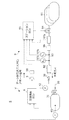
図1は、本実施形態に係る水素充填システムSの構成を示す図である。水素充填システムSは、水素を燃料ガスとして走行する燃料電池車両Vと、この車両Vの水素タンク31に水素ガスを供給する水素ステーション9と、を組み合わせて構成される。以下では、始めに水素ステーション9側の構成について説明し、次に燃料電池車両V側の構成について説明する。
Hereinafter, an embodiment of the present invention will be described with reference to the drawings.
FIG. 1 is a diagram illustrating a configuration of a hydrogen filling system S according to the present embodiment. The hydrogen filling system S is configured by combining a fuel cell vehicle V that travels using hydrogen as a fuel gas and a
水素ステーション9は、車両Vに供給するための水素ガスが高圧で貯蔵されている水素貯蔵タンク91と、水素貯蔵タンク91から作業者が直接操作する充填ノズル92に至る充填流路93と、充填流路93に設けられた流量制御弁94と、流量制御弁94を開閉するステーションECU95と、を備える。
The
ステーションECU95は、充填ノズル92が車両Vに設けられたレセプタクル38に接続されると、後に説明する手順に従って充填態様(充填中における充填流量の可変態様)を決定し、当該充填態様が実現するように流量制御弁94を開閉する。充填ノズル92から放出された水素ガスは、レセプタクル38を介して水素タンク31内に充填される。
When the filling
充填流路93のうち流量制御弁94と充填ノズル92の間には、水素ガスを冷却する冷却器96が設けられる。このような冷却器96によって、水素タンク31に充填される手前の位置で水素ガスを冷却することにより、水素タンク31内の水素ガスの温度上昇を抑制し、ひいては急速充填が可能となる。
A cooler 96 for cooling the hydrogen gas is provided between the
ステーションECU95には、水素タンク31に充填される手前の位置における水素ガスの状態を把握するため、各種センサ97a,97b,97cが接続されている。
流量計97aは、充填流路93のうち流量制御弁94と冷却器96との間に設けられ、流路93を流れる水素ガスの流量に対応した信号をステーションECU95に送信する。以下では、この流量計97aによって検出される水素ガスの流量を、充填流量といい、その値はdm/dtと表記する。また、水素タンク31に充填された水素ガスの量(以下、「総充填量」という)は、例えば充填流量dm/dtを積分することによって算出され、以下ではその値をmと表記する。
The
温度センサ97bは、充填流路93のうち冷却器96と充填ノズル92との間に設けられ、流路93内の水素ガスの温度に対応した信号をステーションECU95に送信する。以下では、この温度センサ97aによって検出される水素ガスの温度を充填ガス温度といい、その値はTSTと表記する。
The
圧力センサ97cは、充填流路93のうち冷却器96と充填ノズル92との間に設けられ、流路93内の水素ガスの圧力に対応した信号をステーションECU95に送信する。以下では、この圧力センサ97cによって検出される水素ガスの圧力を充填ガス圧力といい、その値はPSTと表記する。
The
充填ノズル92には、車両Vと通信するための赤外線通信機98が設けられている。赤外線通信機98は、充填ノズル92をレセプタクル38に接続すると、車両Vに設けられた後述の赤外線通信機5に対向し、これら通信機98,5間で赤外線を介したデータ信号の送受信が可能となる。以下では、これら通信機98,5間での赤外線を介した通信をIR通信という。
The filling
ステーションECU95は、車両Vへの水素ガスの充填にあたって、上記IR通信を利用した通信充填と呼称される充填方法と、IR通信を利用しない非通信充填と呼称される充填方法との2つの充填方法を選択的に実行できる。
The
通信充填とは、車両V及びステーション9間でIR通信を行いながら、車両Vに水素ガスを充填する充填方法である。通信充填では、ステーションECU95は、車両Vの水素タンク31に関する情報を含んだデータ信号を赤外線通信機95によって受信し、このデータ信号に基づいて定めた充填態様で水素タンク31に水素ガスを充填する。ステーションECU95は、通信充填中に受信したデータ信号に基づいて、既知の方法によって水素タンク31内の水素の充填率(以下、「水素SOC」ともいう)を逐次算出し、この水素SOCが所定の満充填閾値を超えた場合には、水素ガスの充填が完了したと判断し、水素ガスの充填を終了する。またステーションECU95は、水素タンク31内の温度が所定のフェール温度に達した場合、データ信号を受信できなくなった場合、又は通信充填中に後述のアボート信号を受信した場合には、水素SOCが満充填閾値に達していない場合であっても、データ信号を用いた水素ガスの充填を中止する。このため通信充填では、満充填に達するまでの間に水素タンク31内の温度がフェール温度を超えないように、かつできるだけ速やかに水素ガスが充填されるように充填態様を決定することが重要となっている。
The communication filling is a filling method in which the vehicle V is filled with hydrogen gas while performing IR communication between the vehicle V and the
またこの通信充填は、車両Vからステーション9へ送信するデータ信号に含まれる情報の種類、すなわちステーションECU95で実行される充填制御で用いられる情報の種類に応じて、一般通信充填と呼称される充填方法と、固有通信充填と呼称される充填方法に分けられる。
This communication filling is a filling called general communication filling according to the type of information included in the data signal transmitted from the vehicle V to the
一般通信充填では、車両V側からは、水素タンク31の温度や圧力等で構成されるタンク状態情報を含むデータ信号が送信される。なお本発明では、タンク状態情報とは、水素タンク31内の水素ガスの温度や圧力等、水素タンク31に設けられたセンサによって検出される物理量の値であると定義する。ステーションECU95は、車両Vから送信されるタンク状態情報を含むデータ信号を受信し、このデータ信号に基づいて決定した充填態様で水素ガスを充填する。
In the general communication filling, the vehicle V side transmits a data signal including tank state information including the temperature and pressure of the
固有通信充填では、車両V側からは、上記タンク状態情報に加えて、水素タンク31の固有情報を含むデータ信号が送信される。本発明では、水素タンク31の固有情報とは、例えば、熱容量値やMCパラメータ値(例えば、本願出願人による特表2013−527390号公報参照)等の水素タンク31の放熱特性を表す値、水素タンク31の容積値、水素タンク31のライナーの材質、及び水素タンク31の製造情報等であって、基本的には水素タンク31が製造された時点で実験を行うことによって特定できる値であると定義する。ステーションECU95は、車両Vから送信されるタンク状態情報及びタンク固有情報を含むデータ信号を受信し、このデータ信号に基づいて決定した充填態様で水素ガスを充填する。
In the unique communication filling, a data signal including unique information of the
ここで、固有通信充填と一般通信充填とを比較する。固有通信充填では、ステーション側へ一般通信充填では送信されない水素タンク31の固有情報が送信される。この固有情報は、上述のように放熱特性を表す値等が含まれていることから、固有通信充填では、車両に搭載されている水素タンク31の特性(熱引きの良し悪し等)を把握して、その時の水素タンク31内の物理状態だけでなく水素タンク31の特性に合わせて最適な充填態様を決定することができる。このため、固有通信充填と一般通信充填とを比較すれば、固有通信充填の方がより速やかに満充填にできる。一般通信充填では、ステーションは水素タンク31の特性を把握できないため、高速充填を行う上で最も熱特性の悪い水素タンクを想定して、充填中に温度が過剰に高くならないように充填流量等にマージンを設けざるを得ず、満充填にするためにかかる時間は固有通信充填よりも長くなってしまう。特に固有情報を用いると充填中における水素タンク31の表面からの放熱の影響を精度良く把握できるため、固有通信充填では充填中及び充填完了予定時における水素タンク31内の温度を精度良く予測することができる。このように固有通信充填では、ステーションECU95は、水素タンク31の将来の状態を精度良く予測しながら水素を充填できるため、充填中に水素タンク31の温度が上記フェール温度を上回らないようにしながら、上記一般通信充填と比較してより速やかに満充填にできる。
Here, the specific communication filling and the general communication filling are compared. In the specific communication filling, the unique information of the
ところで、本願出願人による特表2013−527390号公報には、MC手法なる固有通信充填の新規のアルゴリズムの具体的な手順が示されている。充填完了予定時における水素タンク31内の温度を予測するためには、充填中にタンク壁に吸収される熱量を推定する必要がある。また、このタンク壁に吸収される熱量を厳密に算出するには、充填中におけるタンク壁の温度分布解が必要となるが、これを得るのは非常に困難である。MC手法は、この演算を簡略化すべく質量と比熱容量の合成値MC[kJ/K](特表2013−527390号公報の図5等参照)を導入することによって、充填中の水素タンク31内の温度を、タンク壁からの放熱を考慮しながら予測する。本発明で定義する固有情報には、このようなMC手法に基づく固有通信充填において用いられるMCパラメータ値や、このMCパラメータ値を予め定められたアルゴリズムに従って算出するために必要となる水素タンク31固有の定数値等も含まれる。
By the way, in Japanese translations of PCT publication No. 2013-527390 by the applicant of the present application, a specific procedure of a new algorithm for filling unique communication which is an MC method is shown. In order to predict the temperature in the
非通信充填とは、車両V及びステーション9間でIR通信を行うことなく車両Vに水素を充填する充填方法である。非通信充填では、ステーションECU95は、予め定められた規定の充填態様で水素タンク31に水素ガスを充填する。ステーションECU95は、非通信充填時には水素タンク31の現在の状態を把握できないため、充填中に過充填や過昇温が発生しないように、通信充填と比較して低い圧力(すなわち、低充填率)で充填を終了する。したがって、上記2つの通信充填と非通信充填とを比較すると、通信充填の方が水素タンク31の状態を把握しながら充填するため、満充填又はその付近まで充填できる。
The non-communication filling is a filling method in which the vehicle V is filled with hydrogen without performing IR communication between the vehicle V and the
燃料電池車両Vは、ステーション9から供給された水素ガスを貯蔵する水素タンク31と、この水素タンク31に貯蔵された水素ガスによって発電し、発電した電力を利用して走行する燃料電池システム(図示せず)と、通信充填時に水素タンク31に関するデータ信号をステーション9の赤外線通信機95へ送信する赤外線通信機5と、この赤外線通信機5から送信するデータ信号を生成する充填演算ECU6と、を備える。
The fuel cell vehicle V stores a
水素タンク31は、水素導入管39によってレセプタクル38と接続されている。すなわち、レセプタクル38に接続された水素充填ノズル92から排出された水素ガスは、水素導入管39を介して水素タンク31に充填される。
The
通信演算ECU6には、上述の水素タンク31に関する情報を取得する手段として、温度センサ41と、圧力センサ42と、が接続されている。温度センサ41は、水素タンク31内の水素ガスの温度を検出し、検出値に対応した信号を通信演算ECU6に送信する。以下では、この温度センサ41によって検出される水素タンク31内の水素ガスの温度をタンク内温度といい、その値はTと表記する。圧力センサ42は、水素タンク31内の圧力を検出し、検出値に対応した信号を通信演算ECU6に送信する。以下では、この圧力センサ42によって検出される水素タンク31内の水素ガスの温度をタンク内圧力といい、その値はPと表記する。また以下では特に、充填開始直前のタンク内圧力の値をP0と表記し、充填によるタンク内圧力の上昇分をΔP(=P−P0)と表記する。
A temperature sensor 41 and a
通信演算ECU6は、マイクロコンピュータを含む計算機であり、CPU(中央処理装置)、ROM及びRAM等の記憶媒体、並びに各種インターフェース等の電子回路を含んで構成される。通信演算ECU6のROMには、車両Vが製造された時点で搭載されていた水素タンク31に関する固有情報が記録されている。通信演算ECU6は、水素タンク31に関する情報を赤外線通信機5を介してステーションECU95へ送信するため、タンク内温度の検出値T、タンク内圧力の検出値P、及び固有情報に応じたデータ信号を生成する。以下では、水素タンク31の容積値V及び上述のMCパラメータ値MCの2つのパラメータを固有情報として送信する場合について説明するが、固有情報の種類はこれらに限られない。なお、上述の上昇圧ΔPは、通信演算ECU6で算出し、上記検出値T,Pと併せてステーションECU95へ送信することもできるし、通信演算ECU6から送信される検出値Pに基づいてステーションECU95で算出することもできる。以下では、上昇圧ΔPをステーションECU95で算出する場合について説明する。
The
赤外線通信機5は、例えば赤外線LEDとそのドライバ等で構成される。ドライバは、通信演算ECU6によって生成されたデータ信号及びアボート信号に応じた態様で赤外線LEDを点滅させる。
The
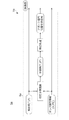
次に、図2を参照しながら、水素充填システムSにおける固有通信充填の具体的な手順について説明する。
図2は、水素充填システムSにおける固有通信充填の具体的な手順を示す機能ブロック図である。図2に示す機能は、車両に搭載される通信演算ECU6における演算、ステーションに搭載されるステーションECU95における演算、及びこれらECU6,95間のIR通信によって実現される。
Next, with reference to FIG. 2, a specific procedure of specific communication filling in the hydrogen filling system S will be described.
FIG. 2 is a functional block diagram showing a specific procedure of specific communication filling in the hydrogen filling system S. The functions shown in FIG. 2 are realized by calculation in the
通信演算ECU6は、固有通信充填を実行するのに必要となるタンク状態情報及びタンク固有情報を、IR通信を利用してステーションECU95へ送信する。車両側からステーション側へ送信される情報は、例えば、タンク内温度の検出値T、タンク内圧力の検出値P、水素タンクの容積値V、及びMCパラメータ値MCの4つである。
The
ステーションECU95は、車両側から送信された情報(T,P,V,MC等)、車両側から送信された情報に基づいてステーション側で算出される情報(ΔP等)、及びステーション側のセンサで取得される情報(例えば、充填ガス圧力の検出値PST、充填ガス温度の検出値TST、充填流量の検出値dm/dt、総充填量m等)を用いて、特性予測演算、検証処理、及び充填制御等の処理を行う。以下、ステーションECU95において実行されるこれら3つの処理の具体的な手順について説明する。
The
<特性予測演算>
特性予測演算では、ステーションECU95は、取得した情報(T,P,V,MC,ΔP,PST,TST,dm/dt,m等)を入力情報として用い、所定のアルゴリズムに従って充填中の水素タンクの状態に関する所定の物理量の予測値を充填中に逐次算出する。ここで「物理量の値を予測する」とは、演算を実行する時点においてステーションECU95で把握できる値に基づいて、対象とする物理量の将来の未知の値或いは値の推移を推定すること、又は対象とする物理量について、これを直接的に検出するセンサの出力以外のパラメータを用いて間接的に推定すること等を含む。特性予測演算において上記複数の入力情報(P,T,V,MC,ΔP,PST,TST,dm/dt,m等)に基づいて予測する物理量は、例えば、充填中のタンク内温度の予測値T´と、充填中のタンク内圧力の予測値P´と、充填によるタンク内圧力の上昇分の予測値ΔP´と、水素タンクの容積の予測値V´と、総充填量の予測値m´との5つである。
<Characteristic prediction calculation>
In the characteristic prediction calculation, the
充填中のタンク内温度の予測値T´は、例えば上記複数の入力情報のうち特に充填圧力検出値PST、充填温度検出値TST、充填流量検出値dm/dt、MCパラメータ値MC、及び容積値Vを予め定められた演算アルゴリズムに入力することによって、算出することができる。なお、MCパラメータ値MC等を用いて温度予測値T´を算出する具体的な演算アルゴリズムについては、本願出願人による特表2013−527390号公報に記載されているので、ここでは詳細な説明を省略する。 The predicted value T ′ of the tank internal temperature during filling is, for example, among the plurality of input information, in particular, the filling pressure detection value P ST , the filling temperature detection value T ST , the filling flow rate detection value dm / dt, the MC parameter value MC, and The volume value V can be calculated by inputting it into a predetermined calculation algorithm. In addition, since the specific calculation algorithm which calculates temperature predicted value T 'using MC parameter value MC etc. is described in the Japanese translations of PCT publication No. 2013-527390 by this applicant, detailed description is given here. Omitted.
充填中のタンク内圧力の予測値P´は、例えば上記複数の入力情報のうち特に充填圧力検出値PST、充填温度検出値TST、及び充填流量検出値dm/dtに基づいて算出することができる。より具体的には、予測値P´は、充填圧力検出値PSTから、圧損dP(例えば、充填圧力検出値PST、充填温度検出値TST、充填流量検出値dm/dtから推定される)を減算することによって算出される。充填によるタンク内圧力の上昇分の予測値ΔP´は、所定の状態方程式を利用し、例えば上記複数の入力情報のうち特に総充填量m、タンク内温度検出値T、及び容積値Vに基づいて算出できる。 The predicted value P ′ of the tank pressure during filling is calculated based on, for example, the filling pressure detection value P ST , the filling temperature detection value T ST , and the filling flow rate detection value dm / dt, among the plurality of input information. Can do. More specifically, the predicted value P ′ is estimated from the detected pressure value P ST from the pressure loss dP (for example, the detected pressure value P ST , the detected temperature value T ST , and the detected detected flow rate value dm / dt). ) Is subtracted. The predicted value ΔP ′ of the increase in the tank internal pressure due to filling is based on, for example, the total filling amount m, the tank temperature detection value T, and the volume value V among the plurality of input information, for example, using a predetermined equation of state. Can be calculated.
水素タンクの容積予測値V´は、所定の状態方程式を利用し、例えば上記複数の入力情報のうち特に総充填量m、タンク内温度検出値T、及びタンク内圧力の上昇分ΔPに基づいて算出できる。また総充填量予測値m´は、所定の状態方程式を利用し、例えば上記複数の入力情報のうち特にタンク内圧力の上昇分ΔP、容積値V、及び温度送信値Tに基づいて算出できる。 The predicted volume V ′ of the hydrogen tank uses a predetermined state equation, and is based on, for example, the total filling amount m, the tank temperature detection value T, and the tank pressure increase ΔP among the plurality of input information. It can be calculated. The predicted total filling amount m ′ can be calculated based on, for example, the increase ΔP in the tank pressure, the volume value V, and the temperature transmission value T among the plurality of input information using a predetermined state equation.
<検証処理>
検証処理では、ステーションECU95は、上記特性予測演算によって逐次算出される5つの予測値(T´,P´,V´,ΔP´,m´)と、充填中に車両側から逐次送信される実値(T,P,V)及びステーション側で取得される実値(ΔP,m)とを比較し、各予測値と実値とが一致しているか否かを判別する。
<Verification process>
In the verification process, the
より具体的には、検証処理では、ステーションECU95は、充填中に車両側から逐次送信されるタンク内温度T、タンク内圧力P及び容積値V並びにこれら送信値等に基づいて算出される圧力差ΔP及び充填流量mを取得し、これらを取得した時刻と対応する時刻における温度予測値T´圧力予測値P´、容積予測値V´、圧力差の予測値ΔP´及び充填流量の予測値m´とを比較し、これら予測値T´,P´,V´,ΔP´,m´がそれぞれ実値T,P,V,ΔP,mを中心とした所定の許容誤差範囲内であるか否かを、固有通信充填を行っている間、継続して判別し、範囲内であれば一致していると判別し、範囲外であれば一致していないと判別する。
More specifically, in the verification process, the
例えば、車両に搭載されている水素タンクに異常が生じた場合(より具体的には、例えば、車両に搭載される水素タンクが、車両製造時のものとは異なる種類のものに交換された場合)、車両側から送信されるMCパラメータ値MC及び容積値Vが、その時搭載されている水素タンクの本来の値からずれが生じる場合がある。この場合、予測値(T´,P´,ΔP´,V´,m´)と実値(T,P,ΔP,V,m)とがずれる場合がある。したがって、検証処理によって、上記予測値のうち何れかがそれぞれの実値と一致していないと判別された場合には、水素タンクに異常が生じたと判断できる。 For example, when an abnormality occurs in the hydrogen tank mounted on the vehicle (more specifically, for example, when the hydrogen tank mounted on the vehicle is replaced with a different type from that used when the vehicle is manufactured) ), The MC parameter value MC and the volume value V transmitted from the vehicle side may deviate from the original values of the hydrogen tank installed at that time. In this case, the predicted value (T ′, P ′, ΔP ′, V ′, m ′) may be different from the actual value (T, P, ΔP, V, m). Therefore, when it is determined by the verification process that any one of the predicted values does not match the actual value, it can be determined that an abnormality has occurred in the hydrogen tank.
例えば、車両に搭載されている温度センサ又は圧力センサに異常が生じた場合(より具体的には、例えば、各センサがドリフト故障した場合や、オフセット故障した場合等)、車両側から送信されるタンク内温度検出値T又はタンク内圧力検出値Pが、本来の値からずれる場合がある。この場合も、予測値(T´,P´,ΔP´,V´,m´)と実値(T,P,ΔP,V,m)とがずれる場合がある。したがって、検証処理によって、上記予測値のうち何れかがそれぞれの実値と一致していないと判別された場合には、温度センサ又は圧力センサに異常が生じたと判断できる。 For example, when an abnormality occurs in a temperature sensor or a pressure sensor mounted on the vehicle (more specifically, for example, when each sensor has a drift failure or an offset failure), it is transmitted from the vehicle side. The tank temperature detection value T or the tank pressure detection value P may deviate from the original value. Also in this case, the predicted values (T ′, P ′, ΔP ′, V ′, m ′) may be different from the actual values (T, P, ΔP, V, m). Therefore, when it is determined by the verification process that any one of the predicted values does not match the actual value, it can be determined that an abnormality has occurred in the temperature sensor or the pressure sensor.
また例えば、通信演算ECUに異常が生じた場合(より具体的には、例えば通信演算ECUが、車両製造時に搭載されていたものとは異なる種類のものに交換された場合、通信演算ECUが正常に作動しなかった場合、データ信号に化けが生じた場合等)、車両側から送信されるタンク内温度検出値T、タンク内圧力検出値P、容積値V及びMCパラメータ値MC等が、本来の値からずれてしまう場合がある。この場合も、予測値(T´,P´,ΔP´,V´,m´)と実値(T,P,ΔP,V,m)とがずれる場合がある。したがって、検証処理によって、上記予測値のうち何れかがそれぞれの実値と一致していないと判別された場合には、通信演算ECUに異常が生じたと判断できる。 Further, for example, when an abnormality occurs in the communication calculation ECU (more specifically, for example, when the communication calculation ECU is replaced with a different type from that installed at the time of vehicle manufacture, the communication calculation ECU is normal. In the case where the data signal is garbled, the tank temperature detection value T, the tank pressure detection value P, the volume value V, the MC parameter value MC, etc. transmitted from the vehicle side May deviate from this value. Also in this case, the predicted values (T ′, P ′, ΔP ′, V ′, m ′) may be different from the actual values (T, P, ΔP, V, m). Therefore, when it is determined by the verification process that any one of the predicted values does not match the actual value, it can be determined that an abnormality has occurred in the communication arithmetic ECU.
図3は、充填中に特性予測演算によって算出されるタンク内温度予測値T´と、車両から送信されるタンク内温度検出値Tとを比較した図である。図3には、予測値T´を破線で示し、検出値Tを実線で示す。 FIG. 3 is a diagram comparing the predicted tank temperature T ′ calculated by the characteristic prediction calculation during filling with the detected tank temperature T transmitted from the vehicle. In FIG. 3, the predicted value T ′ is indicated by a broken line, and the detected value T is indicated by a solid line.
上述のように、水素タンクやセンサ等に異常がない場合であれば、特性予測演算によって算出される予測値T´の推移と、充填中に車両から送信される検出値Tの推移とはほぼ一致する。特に、本発明では、予測値T´を算出するに当たり、水素タンクの放熱特性に関するMCパラメータ値MCを用いることから、図3の左側に示すように、充填開始直後から充填終了時までの間の温度を精度良く予測することができる。 As described above, if there is no abnormality in the hydrogen tank, the sensor, etc., the transition of the predicted value T ′ calculated by the characteristic prediction calculation and the transition of the detection value T transmitted from the vehicle during filling are almost the same. Match. In particular, in the present invention, since the MC parameter value MC related to the heat dissipation characteristics of the hydrogen tank is used in calculating the predicted value T ′, as shown on the left side of FIG. The temperature can be accurately predicted.
一方、水素タンクが交換された場合、水素タンクに搭載されるセンサが故障した場合、通信演算ECUに異常が生じた場合等には、特性予測演算によって算出される予測値T´の推移と充填中に車両から送信される検出値Tの推移とは一致しない(図3の右側参照)。また、故障が生じた場合の予測値T´と検出値Tとの乖離は、水素タンク内の温度の変化が大きくなるほど、換言すれば充填を開始してから経過した時間が長くなるほど大きくなると考えられる。したがって本発明によれば、充填初期時だけでなく充填中は継続して予測値と実値とを比較し、異常の有無を判断することにより、異常が生じていた場合にはこれを精度良く検出できる。 On the other hand, when the hydrogen tank is replaced, when a sensor mounted on the hydrogen tank breaks down, or when an abnormality occurs in the communication calculation ECU, the transition and filling of the predicted value T ′ calculated by the characteristic prediction calculation It does not coincide with the transition of the detection value T transmitted from the vehicle (see the right side of FIG. 3). In addition, the difference between the predicted value T ′ and the detected value T when a failure occurs is considered to increase as the temperature change in the hydrogen tank increases, in other words, as the time elapsed from the start of filling increases. It is done. Therefore, according to the present invention, not only at the initial stage of filling but also during filling, the predicted value is continuously compared with the actual value, and the presence or absence of abnormality is judged. It can be detected.
<充填制御>
図2に戻って、充填制御では、ステーションECU9は、車両Vから送信される水素タンクに関する情報(P,T,V,MC)と、ステーション側に設けられたセンサで取得した情報(PST,TST)と、特性予測演算によって算出された予測値(P´、T´)と、に基づいて充填態様を決定し、当該決定した充填態様が実現するように充填流量を制御する。より具体的には、ステーションECU9は、特性予測演算によって算出される充填終了予定時刻におけるタンク内温度の予測値T´が、上述のフェール温度を超えないように、充填態様を決定する。なお、充填中における充填流量は、充填開始から終了までの間で可変させてもよいし、一定としてもよい。
<Filling control>
Returning to FIG. 2, in the filling control, the
また、ステーションECU9は、水素タンクの固有情報(V,MC)を含む情報に基づいて決定した充填態様で水素ガスを充填している間に、上記検証処理によって各予測値(T´,P´,ΔP´,V´,m´)の何れかが実値(T,P,ΔP,V,m)と一致しないと判断された場合には、当初定めた充填態様での水素ガスの充填を中止する。なお、当初定めた充填態様での水素ガスの充填を中止した後は、上述のように車両側の水素タンクやセンサ等に異常が生じたことを考慮してより緩やかな充填態様に切り替えて水素ガスの充填を継続してもよいし、水素ガスの充填を終了(充填流量dm/dt=0)してもよい。なお、充填態様を切り替えて水素ガスの充填を継続する場合には、水素タンクやセンサ等に異常が存在することを考慮して、充填流量及び充填圧力は、切替前よりも切替後の方が小さくなるように新たな充填態様を決定することが好ましい。
In addition, the
以上、本発明の一実施形態について説明したが、本発明はこれらに限らない。例えば上記実施形態では、タンク内温度の予測値T´やタンク内圧力の予測値P´等を算出する特性予測演算と、これら予測値と実値との一致を判別する検証処理とを、ステーション側のステーションECUで実行する場合について説明したが、これら2つの処理は、車両Vに搭載される通信演算ECUで実行することもできる。 As mentioned above, although one Embodiment of this invention was described, this invention is not restricted to these. For example, in the above-described embodiment, the characteristic prediction calculation for calculating the predicted value T ′ of the tank internal temperature, the predicted value P ′ of the tank internal pressure, and the like, and the verification process for determining the coincidence between the predicted value and the actual value are performed by the station. Although the case where it is executed by the station ECU on the side has been described, these two processes can also be executed by the communication arithmetic ECU mounted on the vehicle V.
図4は、車両Vaからステーションへの一方向通信のみ可能な水素充填システムSaにおいて、車両Vaに搭載される通信演算ECU6aで上記特性予測演算及び検証処理を実行する場合における通信演算ECU6aの機能ブロック図である。
FIG. 4 shows a functional block of the
特性予測演算では、通信演算ECU6aは、ステーション側へ送信される状態情報(タンク内温度の検出値T及びタンク内圧力の検出値P)並びに固有情報(容積値V及びMCパラメータ値MC)に基づいて、所定のアルゴリズムに従って、タンク内温度の予測値T´やタンク内圧力の予測値P´等を算出する。
In the characteristic prediction calculation, the
検証処理では、通信演算ECU6aは、上記特性予測演算によって逐次算出される予測値(T´,P´)と、検出値(T,P)とを比較し、各予測値と検出値とが一致しているか否かを判別する。ここで、各予測値と検出値とが一致しないと判別した場合には、ステーションからの水素の充填中止を要求するアボート信号、又は当初ステーション側で定めた充填態様をより緩やかな充填態様に切り替えるよう要求する充填態様切替要求信号を送信する。
In the verification process, the
また上記実施形態では、車両とステーションとの間のIR通信は、車両側からステーション側へのデータ信号の送信のみが可能な一方向通信である場合について説明したが、本発明は、IR通信が双方向通信である場合にも適用できる。双方向通信が可能である場合には、図4に示すように車両側の通信演算ECUで算出した予測値と、図2に示すようにステーション側のステーションECUで算出した予測値とを突き合わせることができるので、検証処理の精度をさらに向上できる。 In the above embodiment, the IR communication between the vehicle and the station has been described as a one-way communication in which only a data signal can be transmitted from the vehicle side to the station side. The present invention can also be applied to bidirectional communication. When two-way communication is possible, the predicted value calculated by the vehicle-side communication calculation ECU as shown in FIG. 4 matches the predicted value calculated by the station-side station ECU as shown in FIG. Therefore, the accuracy of the verification process can be further improved.
また上記実施形態では、車両からステーション側へ、水素タンクの固有情報として容積値V及びMCパラメータ値MCを送信する場合について説明したが、水素タンクの固有情報はこれらに限るものではない。この車両から送信する固有情報は、水素タンクの熱容量に関する情報でもよい。また、固有情報は、この固有情報を受信するステーションで所定の規格に基づいて水素タンクの放熱特性を把握できる情報であれば、それ自身が物理的な意味を有する物理情報でなくても規格によって定められた形式情報(例えば、TYPE3(アルミライナーを用いた高圧水素タンクの総称)、TYPE4(樹脂製ライナーを用いた高圧水素タンクの総称)等のライナーの材質によって分類される形式番号)でもよい。 Moreover, although the said embodiment demonstrated the case where the volume value V and MC parameter value MC were transmitted as a unique information of a hydrogen tank from a vehicle to the station side, the unique information of a hydrogen tank is not restricted to these. The specific information transmitted from the vehicle may be information regarding the heat capacity of the hydrogen tank. In addition, if the unique information is information that allows the station that receives this unique information to grasp the heat dissipation characteristics of the hydrogen tank based on a predetermined standard, it does not depend on the physical information itself that has physical meaning. Defined format information (for example, TYPE3 (generic name of high-pressure hydrogen tank using an aluminum liner), TYPE4 (generic name of high-pressure hydrogen tank using a resin liner), etc.) may be used. .
S,Sa…水素充填システム(燃料充填システム)
V,Va…燃料電池車両
31…水素タンク(燃料タンク)
41…温度センサ(センサ)
42…圧力センサ(センサ)
6,6a…通信演算ECU(予測手段、比較手段)
9…水素ステーション(外部充填装置)
95…ステーションECU(充填制御手段、予測手段、比較手段)
S, Sa ... Hydrogen filling system (fuel filling system)
V, Va ...
41 ... Temperature sensor (sensor)
42 ... Pressure sensor (sensor)
6, 6a ... Communication calculation ECU (prediction means, comparison means)
9 ... Hydrogen station (external filling equipment)
95 ... Station ECU (filling control means, prediction means, comparison means)
Claims (6)
前記燃料タンク内の燃料の状態に関する所定の物理量の値を検出するセンサと、
前記燃料タンクの固有情報と前記センサの検出値に基づいて充填態様を決定し、当該決定した充填態様で前記燃料タンクへ燃料を充填する充填制御手段と、
燃料の充填中における前記物理量の値を前記固有情報に基づいて予測する予測手段と、
前記センサの検出値と前記予測手段の予測値とが一致しているか否かを、前記固有情報に基づいて決定した充填態様で燃料を充填している間、継続して確認する比較手段と、を備え、
前記充填制御手段は、前記比較手段によって検出値と予測値の不一致が確認された場合には、前記固有情報に基づいて決定した充填態様での燃料の充填を中止することを特徴とする燃料充填システム。 A fuel filling system for filling a fuel tank mounted on a fuel cell vehicle with fuel,
A sensor that detects a value of a predetermined physical quantity related to a state of fuel in the fuel tank;
A filling control means for determining a filling mode based on the specific information of the fuel tank and a detection value of the sensor, and filling the fuel tank with the determined filling mode;
Predicting means for predicting the value of the physical quantity during fuel filling based on the specific information;
Comparing means for continuously checking whether or not the detected value of the sensor and the predicted value of the predicting means coincide with each other while filling the fuel in the filling mode determined based on the specific information; With
The filling control means stops fuel filling in a filling mode determined based on the specific information when the comparison means confirms a mismatch between the detected value and the predicted value. system.
前記物理量は、前記燃料タンク内の燃料の温度であることを特徴とする請求項1に記載の燃料充填システム。 The specific information includes a value of a parameter related to heat dissipation characteristics of the fuel tank during fuel filling,
The fuel filling system according to claim 1, wherein the physical quantity is a temperature of fuel in the fuel tank.
前記物理量は、前記燃料タンク内の圧力であることを特徴とする請求項1に記載の燃料充填システム。 The unique information includes a volume value of the fuel tank,
The fuel filling system according to claim 1, wherein the physical quantity is a pressure in the fuel tank.
前記固有情報は、前記燃料タンクの容積値を含み、The unique information includes a volume value of the fuel tank,
前記物理量は、前記燃料タンク内に充填された総燃料量であり、The physical quantity is a total fuel amount filled in the fuel tank,
前記センサは、前記外部充填装置に設けられ前記総燃料量を検出する流量計を含むことを特徴とする請求項1に記載の燃料充填システム。The fuel filling system according to claim 1, wherein the sensor includes a flow meter provided in the external filling device to detect the total fuel amount.
前記燃料電池車両は、前記燃料タンクと、前記センサと、前記センサの検出値に関する情報及び前記固有情報を含むデータ信号を前記外部充填装置へ送信する送信手段を備え、
前記外部充填装置は、前記充填制御手段と、前記予測手段と、前記比較手段とを備えることを特徴とする請求項1から3の何れかに記載の燃料充填システム。 The fuel filling system is divided into the fuel cell vehicle and an external filling device for filling the fuel cell vehicle with fuel,
The fuel cell vehicle includes transmission means for transmitting the fuel tank, the sensor, and a data signal including information related to a detection value of the sensor and the unique information to the external filling device,
The fuel filling system according to any one of claims 1 to 3, wherein the external filling device includes the filling control means, the prediction means, and the comparison means.
前記燃料電池車両は、前記燃料タンクと、前記センサと、前記予測手段と、前記比較手段とを備えることを特徴とする請求項1から3の何れかに記載の燃料充填システム。 The fuel filling system is divided into the fuel cell vehicle and an external filling device for filling the fuel cell vehicle with fuel,
4. The fuel filling system according to claim 1, wherein the fuel cell vehicle includes the fuel tank, the sensor, the prediction unit, and the comparison unit. 5.
Priority Applications (3)
| Application Number | Priority Date | Filing Date | Title |
|---|---|---|---|
| JP2013269736A JP5901608B2 (en) | 2013-12-26 | 2013-12-26 | Fuel filling system |
| US14/580,481 US10295121B2 (en) | 2013-12-26 | 2014-12-23 | Control method for fuel filling system |
| DE102014226959.8A DE102014226959B4 (en) | 2013-12-26 | 2014-12-23 | Control method for a fuel filling system |
Applications Claiming Priority (1)
| Application Number | Priority Date | Filing Date | Title |
|---|---|---|---|
| JP2013269736A JP5901608B2 (en) | 2013-12-26 | 2013-12-26 | Fuel filling system |
Publications (3)
| Publication Number | Publication Date |
|---|---|
| JP2015124830A JP2015124830A (en) | 2015-07-06 |
| JP2015124830A5 JP2015124830A5 (en) | 2016-01-14 |
| JP5901608B2 true JP5901608B2 (en) | 2016-04-13 |
Family
ID=53372322
Family Applications (1)
| Application Number | Title | Priority Date | Filing Date |
|---|---|---|---|
| JP2013269736A Active JP5901608B2 (en) | 2013-12-26 | 2013-12-26 | Fuel filling system |
Country Status (3)
| Country | Link |
|---|---|
| US (1) | US10295121B2 (en) |
| JP (1) | JP5901608B2 (en) |
| DE (1) | DE102014226959B4 (en) |
Families Citing this family (28)
| Publication number | Priority date | Publication date | Assignee | Title |
|---|---|---|---|---|
| FR2978233B1 (en) * | 2011-07-22 | 2016-05-06 | Air Liquide | METHOD FOR FILLING A RESERVOIR WITH PRESSURIZED GAS |
| JP5901608B2 (en) | 2013-12-26 | 2016-04-13 | 本田技研工業株式会社 | Fuel filling system |
| JP6327341B2 (en) * | 2014-05-07 | 2018-05-23 | 日産自動車株式会社 | Fuel gas filling system and fuel gas filling method |
| JP6136022B2 (en) | 2014-11-12 | 2017-05-31 | トヨタ自動車株式会社 | Control method of fuel cell vehicle |
| DE102015218235A1 (en) * | 2015-09-23 | 2017-03-23 | Bayerische Motoren Werke Aktiengesellschaft | Service device for a pressure vessel system |
| JP6645796B2 (en) * | 2015-10-14 | 2020-02-14 | トキコシステムソリューションズ株式会社 | Gas filling equipment |
| US11499677B2 (en) | 2016-04-22 | 2022-11-15 | Tatsuno Corporation | Gas filling apparatus |
| FR3057644B1 (en) * | 2016-10-19 | 2018-10-19 | L'air Liquide, Societe Anonyme Pour L'etude Et L'exploitation Des Procedes Georges Claude | METHOD AND DEVICE FOR FILLING A PRESSURE GAS TANK |
| JP6602829B2 (en) * | 2017-11-22 | 2019-11-06 | 本田技研工業株式会社 | Gas filling method |
| FR3079907B1 (en) * | 2018-04-09 | 2021-01-08 | Air Liquide | TANK FILLING STATION (S) |
| FR3079908B1 (en) * | 2018-04-09 | 2021-02-19 | Air Liquide | TANK FILLING STATION (S) |
| JP7096062B2 (en) * | 2018-04-27 | 2022-07-05 | トキコシステムソリューションズ株式会社 | Gas filling device |
| JP6927925B2 (en) * | 2018-05-30 | 2021-09-01 | Eneos株式会社 | Flow meter failure diagnosis method of measuring machine and hydrogen filling device |
| JP6995989B2 (en) * | 2018-06-07 | 2022-01-17 | 本田技研工業株式会社 | Gas filling method |
| DE102018210961B4 (en) * | 2018-07-04 | 2021-12-09 | Audi Ag | Method for controlling a refueling process for filling a fuel tank device of a motor vehicle with a gaseous fuel, refueling process planning device, refueling device, and motor vehicle |
| US11339926B2 (en) * | 2018-12-05 | 2022-05-24 | Honda Motor Co., Ltd. | Methods and systems for improving hydrogen refueling |
| DE102018133199A1 (en) * | 2018-12-20 | 2020-06-25 | Hps Home Power Solutions Gmbh | Method for storing a medium in a pressure storage device |
| JP6737350B2 (en) * | 2019-01-16 | 2020-08-05 | 株式会社タツノ | Hydrogen filling system and hydrogen filling method |
| JP7134160B2 (en) * | 2019-12-18 | 2022-09-09 | 本田技研工業株式会社 | Gas control device and gas control method |
| JP7256735B2 (en) * | 2019-12-19 | 2023-04-12 | 大陽日酸株式会社 | Hydrogen filling method |
| DE102020115646A1 (en) * | 2020-06-12 | 2021-12-16 | Westenergie Ag | Method for checking an amount of hydrogen gas released to the vehicle when a vehicle is refueled at a hydrogen filling station, as well as a system comprising the vehicle and hydrogen filling station |
| CN115388317A (en) * | 2021-05-24 | 2022-11-25 | 卡明斯公司 | Multi-container fuel filling and storage systems and methods of using the same |
| WO2023080690A1 (en) * | 2021-11-03 | 2023-05-11 | 현대자동차주식회사 | Integrated control system, method, and device, for hydrogen fueling based on real-time control |
| KR102414036B1 (en) * | 2021-11-22 | 2022-06-29 | 주식회사 헥사 | Liquid hydrogen mobile charging station |
| DE102021132182A1 (en) | 2021-12-07 | 2023-06-07 | Deutsche Bahn Aktiengesellschaft | System and method for controlling the filling of a tank container of a vehicle with gaseous hydrogen from a storage container of a supply station |
| CN114216048B (en) * | 2021-12-21 | 2023-07-28 | 格林美(武汉)城市矿山产业集团有限公司 | Gas leakage device for safely discharging hydrogen from vehicle-mounted hydrogen storage cylinder and use method |
| CN116357882A (en) * | 2021-12-28 | 2023-06-30 | 本田技研工业株式会社 | Gas filling method |
| DE102022200234A1 (en) * | 2022-01-12 | 2023-07-13 | Robert Bosch Gesellschaft mit beschränkter Haftung | Method for modeling and/or optimizing a fueling process of a fuel cell system |
Family Cites Families (33)
| Publication number | Priority date | Publication date | Assignee | Title |
|---|---|---|---|---|
| US4731730A (en) * | 1985-04-30 | 1988-03-15 | Smiths Industries Aerospace & Defence Systems Inc. | Universal fuel quantity indicator apparatus |
| NZ229839A (en) * | 1988-08-15 | 1992-01-29 | Sulzer Ag | Cng refueller with temperature and pressure cut-offs |
| JPH0785883A (en) * | 1993-09-10 | 1995-03-31 | Toyota Motor Corp | Abnormality detecting device and control device for abnormal time |
| JP4000608B2 (en) * | 1996-11-07 | 2007-10-31 | トヨタ自動車株式会社 | Hydrogen production filling device and electric vehicle |
| JP4490557B2 (en) * | 2000-06-09 | 2010-06-30 | 本田技研工業株式会社 | Rapid hydrogen filling method |
| DE50113779D1 (en) * | 2000-11-08 | 2008-05-08 | Greenfield Ag | Method for filling a vehicle tank with gas |
| JP4317346B2 (en) * | 2002-03-15 | 2009-08-19 | 本田技研工業株式会社 | Fuel gas filling control device |
| US6889546B2 (en) * | 2002-09-25 | 2005-05-10 | Delphi Technologies, Inc. | Fuel tank interface assembly |
| JP3832413B2 (en) * | 2002-10-08 | 2006-10-11 | 株式会社タツノ・メカトロニクス | Gas fuel supply system |
| JP2005283127A (en) * | 2004-03-26 | 2005-10-13 | Nissan Motor Co Ltd | Fuel amount processor |
| US8122918B2 (en) * | 2005-08-31 | 2012-02-28 | Honda Motor Co. Ltd. | Pressure differential system for controlling high pressure refill gas flow into on board vehicle fuel tanks |
| JP5055883B2 (en) * | 2005-09-07 | 2012-10-24 | トヨタ自動車株式会社 | Hydrogen supply device |
| JP4753244B2 (en) * | 2005-11-15 | 2011-08-24 | 株式会社日本製鋼所 | Hydrogen filling method and hydrogen filling monitoring device for hydrogen storage container |
| JP2007303560A (en) * | 2006-05-11 | 2007-11-22 | Toho Gas Co Ltd | Gas supply device and gas supply method |
| JP5257206B2 (en) * | 2009-03-31 | 2013-08-07 | 株式会社デンソー | Fluid filling system, moving body, and supply equipment |
| JP5525188B2 (en) * | 2009-06-09 | 2014-06-18 | 本田技研工業株式会社 | Hydrogen filling apparatus and hydrogen filling method |
| US20120000574A1 (en) | 2009-07-29 | 2012-01-05 | Toyota Jidosha Kabushiki Kaisha | Gas filling ystem |
| JP5474436B2 (en) * | 2009-07-30 | 2014-04-16 | トヨタ自動車株式会社 | Gas filling system |
| JP5328617B2 (en) * | 2009-11-18 | 2013-10-30 | トヨタ自動車株式会社 | Gas filling system, gas filling method, vehicle |
| JP2011122657A (en) | 2009-12-10 | 2011-06-23 | Toyota Motor Corp | Fuel gas station, fuel gas filling system, and fuel gas filling method |
| JP5261408B2 (en) * | 2010-01-25 | 2013-08-14 | トヨタ自動車株式会社 | Fuel gas station, fuel gas filling system, and fuel gas supply method |
| JP2011153681A (en) * | 2010-01-28 | 2011-08-11 | Toyota Motor Corp | Gas station, gas filling system and gas filling method |
| JP5489752B2 (en) * | 2010-01-29 | 2014-05-14 | トヨタ自動車株式会社 | Gas filling system and vehicle |
| JP5115565B2 (en) * | 2010-02-15 | 2013-01-09 | トヨタ自動車株式会社 | vehicle |
| US20110200900A1 (en) * | 2010-02-17 | 2011-08-18 | Gm Global Technology Operations, Inc. | Feed forward fuel control algorithm to decrease fuel cell vehicle start up time |
| US9347614B2 (en) | 2010-04-21 | 2016-05-24 | Honda Motor Co., Ltd. | Method and system for tank refilling using active fueling speed control |
| US8783303B2 (en) * | 2010-04-21 | 2014-07-22 | Ryan HARTY | Method and system for tank refilling |
| JP5707727B2 (en) * | 2010-04-23 | 2015-04-30 | トヨタ自動車株式会社 | Gas filling method, gas filling system, gas station, and moving body |
| JP5252089B2 (en) * | 2010-04-30 | 2013-07-31 | トヨタ自動車株式会社 | Fuel leak detection device and detection method |
| JP2012013508A (en) * | 2010-06-30 | 2012-01-19 | Toyota Motor Corp | Calculating system for temperature inside fuel tank |
| KR101337908B1 (en) | 2011-12-01 | 2013-12-09 | 기아자동차주식회사 | Hydrogen safety charging system and method using real-time tank deformation data of fuel cell vehicle |
| JP5959463B2 (en) * | 2013-03-27 | 2016-08-02 | 本田技研工業株式会社 | Fuel cell vehicle and moving body |
| JP5901608B2 (en) | 2013-12-26 | 2016-04-13 | 本田技研工業株式会社 | Fuel filling system |
-
2013
- 2013-12-26 JP JP2013269736A patent/JP5901608B2/en active Active
-
2014
- 2014-12-23 DE DE102014226959.8A patent/DE102014226959B4/en active Active
- 2014-12-23 US US14/580,481 patent/US10295121B2/en active Active
Also Published As
| Publication number | Publication date |
|---|---|
| US20150184804A1 (en) | 2015-07-02 |
| US10295121B2 (en) | 2019-05-21 |
| DE102014226959A1 (en) | 2015-07-02 |
| DE102014226959B4 (en) | 2018-10-25 |
| JP2015124830A (en) | 2015-07-06 |
Similar Documents
| Publication | Publication Date | Title |
|---|---|---|
| JP5901608B2 (en) | Fuel filling system | |
| JP6150839B2 (en) | Fuel filling system and fuel filling method thereof | |
| JP6587737B2 (en) | Gas filling method | |
| US11193632B2 (en) | Gas filling method | |
| EP3550198B1 (en) | Gas filling method | |
| US9604535B2 (en) | Vehicle | |
| US10167999B2 (en) | Gas filling method | |
| US8534327B2 (en) | Gas charging apparatus and gas charging method | |
| JP5489752B2 (en) | Gas filling system and vehicle | |
| US11136951B2 (en) | Gas fueling method | |
| JP5271389B2 (en) | Fuel gas utilization device | |
| JP6984251B2 (en) | Fuel cell vehicle | |
| US11411234B2 (en) | Fuel cell system and method for detecting abnormality of fuel cell system | |
| JP2011122657A (en) | Fuel gas station, fuel gas filling system, and fuel gas filling method | |
| JP6083535B2 (en) | Hydrogen filling device | |
| US9923217B2 (en) | Method of controlling fuel cell system | |
| JP2012077858A (en) | Gas filling system, gas filling method, gas filling device and tank mounting device | |
| JP6561746B2 (en) | Gas filling system | |
| JP2017133624A (en) | Fuel gas charging apparatus and fuel gas charging method | |
| JP5299855B2 (en) | vehicle |
Legal Events
| Date | Code | Title | Description |
|---|---|---|---|
| A521 | Written amendment |
Free format text: JAPANESE INTERMEDIATE CODE: A523 Effective date: 20151117 |
|
| A621 | Written request for application examination |
Free format text: JAPANESE INTERMEDIATE CODE: A621 Effective date: 20151127 |
|
| A521 | Written amendment |
Free format text: JAPANESE INTERMEDIATE CODE: A523 Effective date: 20160112 |
|
| TRDD | Decision of grant or rejection written | ||
| A01 | Written decision to grant a patent or to grant a registration (utility model) |
Free format text: JAPANESE INTERMEDIATE CODE: A01 Effective date: 20160216 |
|
| A61 | First payment of annual fees (during grant procedure) |
Free format text: JAPANESE INTERMEDIATE CODE: A61 Effective date: 20160308 |
|
| R150 | Certificate of patent or registration of utility model |
Ref document number: 5901608 Country of ref document: JP Free format text: JAPANESE INTERMEDIATE CODE: R150 |