EP3683470A1 - Luftfeder mit einem kennzeichnungs- oder datenträger - Google Patents
Luftfeder mit einem kennzeichnungs- oder datenträger Download PDFInfo
- Publication number
- EP3683470A1 EP3683470A1 EP19203747.1A EP19203747A EP3683470A1 EP 3683470 A1 EP3683470 A1 EP 3683470A1 EP 19203747 A EP19203747 A EP 19203747A EP 3683470 A1 EP3683470 A1 EP 3683470A1
- Authority
- EP
- European Patent Office
- Prior art keywords
- identification
- bellows
- data carrier
- air spring
- cover
- Prior art date
- Legal status (The legal status is an assumption and is not a legal conclusion. Google has not performed a legal analysis and makes no representation as to the accuracy of the status listed.)
- Granted
Links
Images


Classifications
-
- F—MECHANICAL ENGINEERING; LIGHTING; HEATING; WEAPONS; BLASTING
- F16—ENGINEERING ELEMENTS AND UNITS; GENERAL MEASURES FOR PRODUCING AND MAINTAINING EFFECTIVE FUNCTIONING OF MACHINES OR INSTALLATIONS; THERMAL INSULATION IN GENERAL
- F16F—SPRINGS; SHOCK-ABSORBERS; MEANS FOR DAMPING VIBRATION
- F16F9/00—Springs, vibration-dampers, shock-absorbers, or similarly-constructed movement-dampers using a fluid or the equivalent as damping medium
- F16F9/02—Springs, vibration-dampers, shock-absorbers, or similarly-constructed movement-dampers using a fluid or the equivalent as damping medium using gas only or vacuum
- F16F9/04—Springs, vibration-dampers, shock-absorbers, or similarly-constructed movement-dampers using a fluid or the equivalent as damping medium using gas only or vacuum in a chamber with a flexible wall
-
- G—PHYSICS
- G09—EDUCATION; CRYPTOGRAPHY; DISPLAY; ADVERTISING; SEALS
- G09F—DISPLAYING; ADVERTISING; SIGNS; LABELS OR NAME-PLATES; SEALS
- G09F3/00—Labels, tag tickets, or similar identification or indication means; Seals; Postage or like stamps
- G09F3/02—Forms or constructions
- G09F3/0297—Forms or constructions including a machine-readable marking, e.g. a bar code
-
- F—MECHANICAL ENGINEERING; LIGHTING; HEATING; WEAPONS; BLASTING
- F16—ENGINEERING ELEMENTS AND UNITS; GENERAL MEASURES FOR PRODUCING AND MAINTAINING EFFECTIVE FUNCTIONING OF MACHINES OR INSTALLATIONS; THERMAL INSULATION IN GENERAL
- F16F—SPRINGS; SHOCK-ABSORBERS; MEANS FOR DAMPING VIBRATION
- F16F2230/00—Purpose; Design features
- F16F2230/0047—Measuring, indicating
-
- G—PHYSICS
- G09—EDUCATION; CRYPTOGRAPHY; DISPLAY; ADVERTISING; SEALS
- G09F—DISPLAYING; ADVERTISING; SIGNS; LABELS OR NAME-PLATES; SEALS
- G09F21/00—Mobile visual advertising
- G09F21/04—Mobile visual advertising by land vehicles
Definitions
- the invention relates to an air spring, arranged between a sprung and an unsprung mass, the air spring having an air bellows, which is attached at both ends of the bellows in an airtight manner to a cover or a connecting plate and cover or connecting plates as connecting elements to the sprung or unsprung mass are formed, wherein in the connection area between the bellows and the sprung or unsprung mass there is provided an identification or data carrier provided with a marking or a date, preferably in the form of a film having an identification marking.
- date or “identification” is to be understood here to mean any form of information which contains data, numerical or alphanumeric characters, codes or color codes, including in the form of barcodes, QR codes, signatures, etc.
- Air springs are used today for e.g. Trucks or rail vehicles between sprung body and unsprung chassis part or for industrial applications, such as for air-sprung machine bearings.
- the air bellows is under internal pressure, usually air pressure, between the connecting parts.
- Corresponding pressure lines for the air supply and discharge as well as valve arrangements and controls and associated sensors and controls are known in the prior art.
- the air bellows can be designed as a rolling bellows and roll when deflected on the contours or pistons provided, as is customary for example in trucks, it can also be designed as a half-bellows or multi-bellows, as is often the case with rail vehicles.
- the associated air spring bellows usually have at their ends a bead-like circumferential thickening with an embedded core, ie an edge reinforced with a metallic core ring.
- This reinforced edge is clamped to the respective connection part, ie to the air spring cover or that of a connection plate or to the air spring rim, with a further and generally metallic fastening part.
- the metal fastening part has a cross-section around the reinforced edge of the air bellows from the outside and is fastened to the connection part or cover with screws or threaded bolts / stud bolts. This also clamps the edge of the air bellows so that an airtight connection is created between the air bellows and the connector.
- Air springs for rail vehicles are also usually designed with a bead ring at both ends, with which the bellows is securely fastened and sealed airtight.
- the bellows end is fixed e.g. in the case of a half-bellows, usually also via a separately screwed, ring-shaped fastening element, with which the bellows flange with integrated core or bead ring is pressed against a plate or surface in a positive and non-positive manner.
- a similar connection to the cover or connection plate is provided by multi-bellows, the individual folds of which are separated and contoured by inextensible, often metallic rings which surround the air bellows over its height and are distributed outside at the fold spacing.
- the walls of air suspension bellows are usually provided with reinforcing elements, namely strength members such as cords, thread layers or fabrics.
- air springs are assembled in finished sub-groups and supplied for further processing.
- Such manufacturing in assemblies or components is common today in all areas. With the various applications of air springs and with the significantly different load levels, it is extremely important that the components with a are clearly marked, which enables an error-free and safe allocation to the respective application.
- an air spring with such a marking discloses the US 2006/0043196 A1 .
- the marking is located on a label (label tag) which is clamped at least on one side between the bellows end of the air spring bellows and the respective air spring cover.
- the marking carrier disadvantageously protrudes relatively far from the clamping areas, so that it is constantly exposed to all environmental influences and loads.
- the object of the invention was therefore to provide an air spring, preferably as an assembly consisting of air bellows and mounted end covers or connecting plates, which has a secure, mechanically stable marking or marking that is insensitive to external loads, and its arrangement on or connection to the connecting parts is as simple as possible is designed, whereby the labeling is not permanently exposed to all environmental influences and can only be made visible when it is needed and which can be easily fitted within the usual components without changing the previous design.
- the identification or data carrier is designed to be displaceable between at least a first and a second position, the identification or the date being covered in the first position of the identification or data carrier and invisible or illegible from outside the air spring and uncovered in the second position and is visible or legible
- marking or marking and thus also the marking or data carrier can only emerge or be brought into the second position if the marking or marking is actually used for identification, for example after delivery of the air spring as an assembly for assembly to the truck manufacturing plant.
- the marking or marking need not be noticed during the preliminary transport, during later operation and, for example, also during cleaning measures, so that the marking or data carrier can then remain in its first position or be returned to it.
- Moving the identification or data carrier can of course also involve a further functional action, for example in that, when moving from position 1 to position 2, certain parts of the identification are destroyed or changed by the identification or data carrier or by the identification, so that this can be an indication of a control or data reading that has already been carried out.
- a further advantageous embodiment consists in that the bellows for attachment to the cover or connection plate has at least one bell-shaped end with a bead-like, annular circumferential thickening, optionally provided with a metallic core, and the fastening elements take up or embrace the annular thickening and connect it airtight to the connection plate or cover , and in which the identification or data carrier is arranged between an annular circumferential thickening and connection plate or cover.
- the identification or data carrier is arranged between the fastening element and the connection plate, there is a particularly simple possibility of fastening, which in particular can also be carried out during component manufacture.
- a further advantageous embodiment consists in that a support ring surrounding the respective bellows or fastening element is provided on the connection plate or cover for contacting the air bellows during rolling or walking movements, and the identification or data carrier is arranged between the support ring on the one hand and the cover or connection plate on the other. This also opens up another very simple possibility of fastening the identification or data carrier to the "air spring" assembly.
- a further advantageous embodiment consists in that the identification or data carrier is slidably received in a sleeve or in a guide, preferably in a guide frame, and the sleeve or guide is arranged in the connection area between the bellows and the sprung or unsprung mass.
- Another advantageous embodiment consists in that the identification or data carrier or its cover or guide is clamped or glued in the connection area. As already shown above, these are particularly simple ways of connecting the identification or data carrier or its casing or guide to the other components.
- a further advantageous embodiment consists in the fact that the identification or the date or the identification or data carrier in the first position of the identification or data carrier is covered by components located in the connection area and protrudes uncovered from the components in the second position. In this way it can be achieved in a constructively elegant manner that the external appearance of the air spring is completely unaffected.
- Fig. 1 only shows in principle and in section the upper part of an air spring 1 according to the invention, which is arranged between masses or components not shown here, namely a sprung and an unsprung mass.
- the air spring shown here is used as a secondary spring between a body and a chassis of a railroad car.
- the air spring 1 has an air bellows designed as a bellows 2, which is fastened in an airtight manner at its two bellows ends to a cover or a connecting plate 3, respectively.
- a cover or a connecting plate 3 respectively.
- the bellows 2 For fastening the bellows 2 to the connection plate 3, the bellows 2 has a bead-like, ring-shaped thickening 4 at the upper bell end.
- a likewise annular fastening element 5 encompasses the annular thickening with the aid of a flange located on its edge. The crimping between the fastening element 5 and the annular thickening 4 is carried out in an airtight manner.
- the fastening element 5 is connected to the connecting plate 3 in an airtight manner using screws 6.
- the bellows is connected with its upper end airtight to the connection plate 3.
- connection plate 3 which is provided for supporting or for supporting the bellows 2 during suspension, rolling or flexing movements.
- Fig. 2 shows the support ring 7 again as a single element in cross section.
- Figure 3 shows the support ring 7 in plan view.
- a marking carrier 8 is arranged between the support ring 7 on the one hand and the connecting plate 3 on the other.
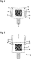
- the identification carrier 8 essentially consists of a trapezoidally cut, stable film 9, which is printed with a machine-readable QR code 10 (Quick Response Code), as can be seen in particular from the overview of the Figures 3 to 5 results.
- the identification carrier 8 is slidably received in a guide frame 11.
- the guide frame 11 is in turn clamped between the support ring 7 on the one hand and the connecting plate 3 on the other and additionally glued in for securing.
- the identification carrier 8 is movably received and guided in the guide frame 11, so that the identification carrier 8 or the trapezoidal film 9 between the in the Figure 4 position shown and in the Figure 5 shown position can be pushed back and forth, possibly against a slight resistance generated by a corresponding fit.
- the identification in this case the QR code, is hidden in the first position of the identification carrier and is invisible or illegible from outside the air spring and uncovered and visible or legible in the second position.
- the label carrier 8 and the guide frame 11 are provided with complementary stops 12 and 13, which prevent the label carrier from being completely removed from the guide frame.
- the label carrier 8 is in this way in the Figure 4
- the first position shown is hidden by components located in the connection area, namely by the support ring 7 and the connecting plate 3, as is also shown in FIGS Fig. 1 and 3rd becomes clear.
- the second position shown protrudes uncovered from these components.
Landscapes
- Engineering & Computer Science (AREA)
- General Engineering & Computer Science (AREA)
- Mechanical Engineering (AREA)
- Physics & Mathematics (AREA)
- General Physics & Mathematics (AREA)
- Theoretical Computer Science (AREA)
- Fluid-Damping Devices (AREA)
- Vehicle Body Suspensions (AREA)
Abstract
Description
- Die Erfindung betrifft eine Luftfeder, angeordnet zwischen einer gefederten und einer ungefederten Masse, wobei die Luftfeder einen Luftfederbalg aufweist, der an seinen beiden Balgenden an jeweils einem Deckel bzw. einer Anschlussplatte luftdicht befestigt ist und Deckel bzw. Anschlussplatten als Verbindungselemente zur gefederten oder ungefederten Masse ausgebildet sind, wobei im Verbindungsbereich zwischen Balgende und gefederter oder ungefederter Masse ein mit einer Kennzeichnung oder einem Datum versehener Kennzeichnungs- oder Datenträger vorgesehen ist, vorzugsweise in Form einer eine Identifizierungskennzeichnung aufweisende Folie. Unter dem Begriff "Datum" oder "Kennzeichnung" ist hier jedwede Form von Information zu verstehen, die Daten, numerische oder alphanumerische Zeichen, Kodierungen oder Farbkennzeichnungen enthält, auch in Form von Barcodes, QR-Codes, Signierungen etc.
- Luftfedern werden heute eingesetzt für z.B. LKW oder Schienenfahrzeuge zwischen gefederter Karosserie und ungefedertem Fahrwerksteil oder für industrielle Anwendungen, wie etwa für luftgefederte Maschinenlagerungen. Zwischen den Anschlussteilen steht der Luftfederbalg unter Innendruck, üblicherweise Luftdruck. Entsprechende Druckleitungen für die Luftzufuhr und Abfuhr sowie Ventilanordnungen und - regelungen und Zugehörige Sensorik und Steuerungen sind im Stand der Technik bekannt. Der Luftfederbalg kann dabei als Rollbalg ausgebildet sein und beim Einfedern an vorgesehenen Konturen oder Kolben abrollen, wie beispielsweise bei LKW üblich, er kann auch als Halbbalg oder Mehrfaltenbalg ausgebildet sein, wie oft bei Schienenfahrzeugen ausgeführt.
- Zur Befestigung der Luftfeder an den Anschlussteilen gibt es unterschiedliche Möglichkeiten. Bei industrieller Anwendung, also etwa bei der Federung von Maschinen, weisen die zugehörigen Luftfederbälge üblicherweise an ihren Enden eine wulstartig umlaufende Verdickung mit einem eingebetteten Kern auf, d.h. einen mit einem metallischen Kernring verstärkten Rand. Dieser verstärkte Rand wird mit einem weiteren und in der Regel metallischen Befestigungsteil an dem jeweiligen Anschlussteil, d.h. am Luftfederdeckel bzw. der einer Anschlussplatte oder an der Luftfederfelge festgeklemmt. Das metallische Befestigungsteil besitzt eine im Querschnitt den verstärkten Rand des Luftfederbalgs von außen umgreifende Form und wird am Anschlussteil oder Deckel mit Schrauben oder Gewindebolzen/Stehbolzen befestigt. Damit wird auch der Rand des Luftfederbalgs so festgeklemmt, dass eine luftdichte Verbindung zwischen Luftfederbalg und Anschlussteil hergestellt ist.
- Auch Luftfedern für Schienenfahrzeuge werden üblicherweise mit jeweils einem Wulstring n beiden Enden ausgeführt, mit denen der Balg sicher befestigt und luftdicht abgedichtet wird. Die Fixierung eines Balgendes erfolgt z.B. bei einem Halbbalg in der Regel ebenfalls über ein separat verschraubtes, ringförmiges Befestigungselement, mit dem der Balgflansch mit integriertem Kern oder Wulstring form- und kraftschlüssig gegen eine Platte bzw. Fläche gepresst wird.
- Eine ähnliche Anbindung an Deckel bzw. Anschlussplatte weisen Mehrfaltenbälge auf, deren einzelne Falten durch nicht dehnbare, oft metallische Ringe getrennt und konturiert werden, welche den Luftfederbalg über seine Höhe verteilt außen im Faltenabstand umgeben.
- Die Wände von Luftfederbälgen sind üblicherweise mit Verstärkungselementen versehen, nämlich Festigkeitsträgern wie Corden, Fadenlagen oder Geweben.
- Um die Montage der Einzelteile zu erleichtern, werden Luftfedern in fertigen Untergruppen zusammengebaut und der Weiterverarbeitung zugeliefert. Solch eine Fertigung in Baugruppen oder Komponenten ist heutzutage in allen Bereichen üblich. Bei den vielfältigen Anwendungen von Luftfedern und bei den erheblich unterschiedlichen Belastungsstufen ist es enorm wichtig, dass insbesondere die Komponenten mit einer deutlichen Kennzeichnung versehen sind, die eine fehlerfreien und sichere Zuordnung zum jeweiligen Anwendungsfall ermöglicht.
- Eine Luftfeder mit einer solchen Kennzeichnung offenbart die
US 2006/0043196 A1 . Bei der dort offenbarten Luftfeder befindet sich die Kennzeichnung auf einem Kennzeichnungsträger (label tag) der mindestens einseitig zwischen dem Balgende des Luftfederbalgs und dem jeweiligen Luftfederdeckel festgeklemmt ist. Nachteiligerweise tritt der Kennzeichnungsträger relativ weit aus dem Klemmbereiche hervor, so dass er allen Umgebungseinflüssen und Belastungen ständig ausgesetzt ist. - Eine solche Luftfeder, als Komponente oder Bauteil während des Transports oder im Einsatz am Fahrzeug, muss oft relativ raue Behandlungen und lange Transportwege überstehen und dennoch jederzeit klar und deutlich identifizierbar sein. Darüber hinaus ist die Befestigung der Kennzeichnung am Bauteil starken mechanische Beanspruchungen unterworfen, die die Kennzeichnung als solche unkenntlich machen oder einen Kennzeichnungsträger zerstören oder ablösen können.
- Zudem muss eine solche Kennzeichnung es auch ermöglichen, eine elektronische oder elektronisch verarbeitbare Identifizierung von Baugruppen oder Komponenten durchzuführen.
- Für die Erfindung bestand daher die Aufgabe, eine Luftfeder bereitzustellen, vorzugsweise als Baugruppe aus Luftfederbalg und montierten endseitigen Deckeln oder Anschlussplatten, die eine sichere, mechanisch stabile und gegen äußere Belastungen unempfindliche Kennzeichnung oder Markierung aufweist, deren Anordnung an oder Verbindung mit den Anschlussteilen möglichst einfach gestaltet ist, wobei die Kennzeichnung zudem nicht dauerhaft allen Umgebungseinflüsse ausgesetzt ist und nur dann sichtbar gemacht werden kann, wenn sie gebraucht wird und die sich ohne Veränderung der bisherigen Konstruktion innerhalb der üblichen Bauteile leicht einpassen lässt.
- Gelöst wird diese Aufgabe durch die Merkmale des Hauptanspruchs. Weitere vorteilhafte Ausbildungen sind in den Unteransprüchen offenbart.
- Dabei ist der Kennzeichnungs- oder Datenträger zwischen mindestens einer ersten und eine zweite Position verschiebbar ausgebildet ist, wobei die Kennzeichnung oder das Datum in der ersten Position des Kennzeichnungs- oder Datenträgers verdeckt und von außerhalb der Luftfeder unsichtbar oder unlesbar und in der zweiten Position unverdeckt und sichtbar oder lesbar angeordnet ist
- Dadurch wird erreicht, dass die Kennzeichnung oder Markierung und damit auch der Kennzeichnungs- oder Datenträger nur dann in die zweite Position hervortritt bzw. hervorgeholt werden kann, wenn die Kennzeichnung oder Markierung tatsächlich zur Identifikation gebraucht wird, beispielsweise nach Anlieferung der Luftfeder als Baugruppe zur Montage an das Lkw-Herstellerwerk. Während des vorlaufenden Transports, während des späteren Betriebs und zum Beispiel auch bei Reinigungsmaßnahmen braucht die Kennzeichnung oder Markierung nicht aufzufallen, so dass der Kennzeichnungs- oder Datenträger dann in seiner erste Position verbleiben kann oder in diese zurückgeführt wird.
- Mit dem Verschieben des Kennzeichnungs- oder Datenträgers kann natürlich auch eine weitere funktionale Handlung verbunden sein, beispielsweise dadurch, dass beim Verschieben von Position 1 in Position 2 bestimmte Kennzeichnungsteile vom der Kennzeichnungs- oder Datenträger oder von der Kennzeichnung zerstört oder verändert werden, so dass dies ein Hinweis auf eine bereits durchgeführte Kontrolle oder Datenauslesung sein kann.
- Eine vorteilhafte Weiterbildung besteht darin, dass Befestigungselemente vorgesehen sind, mit denen das jeweilige Balgende an Deckel bzw. Anschlussplatte luftdicht anschließbar ist, vorzugsweise ausgebildet als Klemm-, Spann- oder Schraubringe. Damit erweitert man die Möglichkeiten der Befestigung auch des Kennzeichnungs- oder Datenträgers, der ja die Kennzeichnung bzw, das Datum trägt und im Verbindungsbereich zwischen Balgende und gefederter oder ungefederter Masse vorgesehen ist. Neben einem Kleben oder einer stoffschlüssigen Verbindung ist damit der Weg eröffnet, auch eine Klemmung des Kennzeichnungs- oder Datenträgers vorzusehen, die auch während der Herstellung der Baugruppe bzw. Komponente bereits auf einfachste Weise erfolgen kann.
- Eine weitere vorteilhafte Ausbildung besteht darin, dass der Balg zur Befestigung an Deckel bzw. Anschlussplatte mindestens an einem Balgende eine gegebenenfalls mit einem metallischen Kern versehene wulstartige, ringförmig umlaufende Verdickung aufweist und die Befestigungselemente die ringförmige Verdickung aufnehmen oder umgreifen und mit Anschlussplatte oder Deckel luftdicht verbinden, und bei der der Kennzeichnungs- oder Datenträger zwischen ringförmig umlaufender Verdickung und Anschlussplatte oder Deckel angeordnet ist. Insbesondere dann, wenn der Kennzeichnungs- oder Datenträger zwischen Befestigungselement und Anschlussplatte angeordnet ist ergibt sich eine besonders einfache Möglichkeit der Befestigung, die insbesondere auch während der Komponentenherstellung bereits ausgeführt werden kann.
- Eine weitere vorteilhafte Ausbildung besteht darin, dass ein das jeweilige Balgende bzw. Befestigungselement umgebender Stützring an Anschlussplatte oder Deckel zur Anlage des Luftfederbalgs bei Roll- oder Walkbewegungen vorgesehen ist und der Kennzeichnungs- oder Datenträger zwischen Stützring einerseits und Deckel bzw. Anschlussplatte andererseits angeordnet ist. Auch damit eröffnet man eine weitere sehr einfache Möglichkeit der Befestigung des Kennzeichnungs- oder Datenträgers an der Baugruppe "Luftfeder".
- Eine weitere vorteilhafte Ausbildung besteht darin, dass der Kennzeichnungs- oder Datenträger in einer Hülle oder in einer Führung, vorzugsweise in einem Führungsrahmen verschiebbar aufgenommen ist und die Hülle oder Führung im Verbindungsbereich zwischen Balgende und gefederter oder ungefederter Masse angeordnet ist. Durch einen solchen Führungsrahmen vermeidet man zum einen, dass in unerwünschter Weise Kräfte auf dem Kennzeichnungsträger als solchen wirken und man erreicht zum anderen ein relativ leichtes Verschieben zwischen den beiden Positionen.
- Eine weitere vorteilhafte Ausbildung besteht darin, dass der Kennzeichnungs- oder Datenträger bzw. dessen Hülle oder Führung im Verbindungsbereich eingeklemmt oder eingeklebt ist. Wie oben bereits dargestellt, sind dies besonders einfache Möglichkeiten, den Kennzeichnungs- oder Datenträger bzw. dessen Hülle oder Führung mit den übrigen Bauteilen zu verbinden.
- Eine weitere vorteilhafte Ausbildung besteht darin, dass die Kennzeichnung oder das Datum bzw. der Kennzeichnungs- oder Datenträger in der ersten Position des Kennzeichnungs- oder Datenträgers durch im Verbindungsbereich befindliche Bauteile verdeckt ist und in der zweiten Position aus den Bauteilen unverdeckt herausragt. Damit lässt sich auf konstruktiv elegante Weise erreichen, dass das äußere Erscheinungsbild der Luftfeder völlig unbeeinflusst ist.
- Anhand eines Ausführungsbeispiels soll die Erfindung näher erläutert werden. Es zeigen
- Fig. 1
- Eine erfindungsgemäße Luftfeder mit einem Kennzeichnungsträger,
- Fig. 2, 3
- den zugehörigen Stützring als einzelnes Element im Querschnitt und in der Draufsicht,
- Fig. 4, 5
- den verschiebbaren Kennzeichnungsträger in seinen beiden Positionen.
-
Fig. 1 zeigt lediglich prinzipiell und im Schnitt den oberen Teil einer erfindungsgemäßen Luftfeder 1, die zwischen hier nicht näher dargestellten Massen bzw. Bauteilen angeordnet ist, nämlich einer gefederten und einer ungefederten Masse. Die hier dargestellte Luftfeder wird als Sekundärfeder zwischen einer Karosserie und einem Fahrwerk eines Eisenbahnwaggons benutzt. - Die Luftfeder 1 weist einen als Faltenbalg 2 ausgebildeten Luftfederbalg auf, der an seinen beiden Balgenden an jeweils einem Deckel bzw. einer Anschlussplatte 3 luftdicht befestigt ist. In der
Fig. 1 ist dabei nur der obere Deckel bzw. die oberer Anschlussplatte dargestellt. - Zur Befestigung des Faltenbalgs 2 an der Anschlussplatte 3 weist der Balg 2 am oberen Balgende eine wulstartige, ringförmig umlaufende Verdickung 4 auf. Ein ebenfalls ringförmiges Befestigungselement 5 umgreift die ringförmige Verdickung mithilfe einer an ihrem Rand befindlichen Bördelung. Die Bördelung zwischen Befestigungselement 5 und ringförmiger Verdickung 4 ist luftdicht ausgeführt. Das Befestigungselement 5 ist mithilfe von Schrauben 6 mit der Anschlussplatte 3 luftdicht verbunden. Der Faltenbalg ist so mit seinem oberen Ende luftdicht an die Anschlussplatte 3 angeschlossen.
- Nicht weiter dargestellt, weil nicht erfindungswesentlich, sind hier die zugehörigen Luftleitungen, Steuerungseinrichtungen und Schaltventile.
- In der
Figur 1 erkennt man weiterhin, dass ein das obere Balgende bzw. Befestigungselement 5 umgebender Stützring 7 an der Anschlussplatte 3 vorgesehen ist, der zur Abstützung bzw. zur Anlage des Faltenbalgs 2 bei Federungs-, Roll- oder Walkbewegungen vorgesehen ist. -
Fig. 2 zeigt den Stützring 7 noch einmal als einzelnes Element im Querschnitt.Figur 3 zeigt den Stützring 7 in der Draufsicht. - In der Zusammenschau der
Figuren 1 bis 3 erkennt man nun, dass zwischen Stützring 7 einerseits und Anschlussplatte 3 andererseits ein Kennzeichnungsträger 8 angeordnet ist. Der Kennzeichnungsträger 8 besteht hierbei im Wesentlichen aus einer trapezförmig geschnittenen, stabilen Folie 9, die mit einem maschinenlesbarem QR-Code 10 (Quick Response Code) bedruckt ist, wie sich insbesondere aus der Zusammenschau derFiguren 3 bis 5 ergibt. - Wie am deutlichsten in den
Figuren 4 und 5 dargestellt, ist der Kennzeichnungsträger 8 in einem Führungsrahmen 11 verschiebbar aufgenommen. Der Führungsrahmen 11 wiederum ist zwischen Stützring 7 einerseits und Anschlussplatte 3 andererseits eingeklemmt und zur Sicherung zusätzlich eingeklebt. - Dabei ist der Kennzeichnungsträger 8 im Führungsrahmen 11 beweglich aufgenommen und geführt, so dass der Kennzeichnungsträger 8 bzw. die trapezförmige Folie 9 zwischen der in der
Figur 4 dargestellten Position und der in derFigur 5 dargestellten Position hin und her geschoben werden kann, gegebenenfalls gegen einen leichten, durch eine entsprechenden Passung erzeugten Widerstand. Die Kennzeichnung, hier also der QR-Code, ist in der ersten Position des Kennzeichnungsträgers verdeckt und von außerhalb der Luftfeder unsichtbar oder unlesbar und in der zweiten Position unverdeckt und sichtbar oder lesbar angeordnet ist. - Der Kennzeichnungsträger 8 und der Führungsrahmen 11 sind dabei mit komplementär wirkenden Anschlägen 12 und 13 versehen, die verhindern, dass der Kennzeichnungsträger komplett aus den Führungsrahmen entfernt werden kann.
- Der Kennzeichnungsträger 8 ist auf diese Weise in der in der
Figur 4 gezeigten ersten Position durch im Verbindungsbereich befindliche Bauteile verdeckt, nämlich durch den Stützring 7 und die Anschlussplatte 3, wie dies auch in denFig.1 und3 deutlich wird. In der zweiten und in derFigur 5 dargestellten zweiten Position ragt der Kennzeichnungsträger aus diesen Bauteilen unverdeckt heraus. -
- 1
- Luftfeder
- 2
- Faltenbalg
- 3
- Anschlussplatte
- 4
- ringförmig umlaufende Verdickung
- 5
- Befestigungselement
- 6
- Schraube
- 7
- Stützring
- 8
- Kennzeichnungsträger
- 9
- trapezförmige Folie
- 10
- QR-Code
- 11
- Führungsrahmen
- 12
- Anschlag
- 13
- Anschlag
Claims (7)
- Luftfeder (1), angeordnet zwischen einer gefederten und einer ungefederten Masse, wobei die Luftfeder einen Luftfederbalg (2) aufweist, der an seinen beiden Balgenden an jeweils einem Deckel bzw. einer Anschlussplatte (3) luftdicht befestigt ist und Deckel bzw. Anschlussplatten als Verbindungselemente zur gefederten oder ungefederten Masse ausgebildet sind, wobei im Verbindungsbereich zwischen Balgende und gefederter oder ungefederter Masse ein mit einer Kennzeichnung oder einem Datum (10) versehener Kennzeichnungs- oder Datenträger (8) vorgesehen ist, vorzugsweise in Form einer eine Identifizierungskennzeichnung aufweisende Folie (9), dadurch gekennzeichnet, dass der Kennzeichnungs- oder Datenträger (8) zwischen mindestens einer ersten und einer zweiten Position verschiebbar ausgebildet ist, wobei die Kennzeichnung oder das Datum (10) in der ersten Position des Kennzeichnungs- oder Datenträgers (8) verdeckt und von außerhalb der Luftfeder (1) unsichtbar oder unlesbar und in der zweiten Position unverdeckt und sichtbar oder lesbar angeordnet ist.
- Luftfeder nach Anspruch 1, bei der mindestens ein Befestigungselement (5) vorgesehen ist, mit denen das jeweilige Balgende an Deckel bzw. Anschlussplatte (3) luftdicht anschließbar ist, vorzugsweise ausgebildet als Klemm-, Spann- oder Schraubringe, und wobei der Kennzeichnungs- oder Datenträgers (8) im Zusammenwirken mit dem Befestigungselement (5) im Verbindungsbereich angeordnet ist.
- Luftfeder nach Anspruch 1 oder 2, bei der der Balg (2) zur Befestigung an Deckel bzw. Anschlussplatte mindestens an einem Balgende eine gegebenenfalls mit einem metallischen Kern versehene wulstartige, ringförmig umlaufende Verdickung (4) aufweist und die Befestigungselemente (5) die ringförmige Verdickung aufnehmen oder umgreifen und mit Anschlussplatte oder Deckel (3) luftdicht verbinden, und bei der der Kennzeichnungs- oder Datenträger (8, 9) zwischen ringförmig umlaufender Verdickung (4) und Anschlussplatte oder Deckel angeordnet ist, vorzugsweise zwischen Befestigungselement (5) und Anschlussplatte (3).
- Luftfeder nach einem der Ansprüche 1 bis 3, bei der ein das jeweilige Balgende bzw. Befestigungselement umgebender Stützring (7) an Anschlussplatte oder Deckel zur Anlage des Luftfederbalgs (2) bei Federungs-, Roll- oder Walkbewegungen vorgesehen ist und der Kennzeichnungs- oder Datenträger (8) zwischen Stützring (7) einerseits und Deckel bzw. Anschlussplatte (3) andererseits angeordnet ist.
- Luftfeder nach einem der Ansprüche 1 bis 4, bei der der Kennzeichnungs- oder Datenträger in einer Hülle oder in einer Führung, vorzugsweise in einem Führungsrahmen (11) verschiebbar aufgenommen ist und die Hülle oder Führung im Verbindungsbereich zwischen Balgende und gefederter oder ungefederter Masse angeordnet ist.
- Luftfeder nach einem der Ansprüche 1 bis 5, bei der der Kennzeichnungs- oder Datenträger (8) bzw. dessen Hülle oder Führung (11) im Verbindungsbereich eingeklemmt oder eingeklebt ist.
- Luftfeder nach einem der Ansprüche 1 bis 6, bei der die Kennzeichnung oder das Datum (10) bzw. der Kennzeichnungs- oder Datenträger (8) in der ersten Position des Kennzeichnungs- oder Datenträgers durch im Verbindungsbereich befindliche Bauteile verdeckt ist und in der zweiten Position aus den Bauteilen unverdeckt herausragt.
Applications Claiming Priority (1)
| Application Number | Priority Date | Filing Date | Title |
|---|---|---|---|
| DE102018222462.5A DE102018222462A1 (de) | 2018-12-20 | 2018-12-20 | Luftfeder mit einem Kennzeichnungs- oder Datenträger |
Publications (2)
| Publication Number | Publication Date |
|---|---|
| EP3683470A1 true EP3683470A1 (de) | 2020-07-22 |
| EP3683470B1 EP3683470B1 (de) | 2024-01-03 |
Family
ID=68281273
Family Applications (1)
| Application Number | Title | Priority Date | Filing Date |
|---|---|---|---|
| EP19203747.1A Active EP3683470B1 (de) | 2018-12-20 | 2019-10-17 | Luftfeder mit einem kennzeichnungs- oder datenträger |
Country Status (2)
| Country | Link |
|---|---|
| EP (1) | EP3683470B1 (de) |
| DE (1) | DE102018222462A1 (de) |
Citations (3)
| Publication number | Priority date | Publication date | Assignee | Title |
|---|---|---|---|---|
| WO2001027905A1 (en) * | 1999-10-14 | 2001-04-19 | The Goodyear Tire & Rubber Company | Part number identification tag |
| US20060043196A1 (en) | 2004-08-27 | 2006-03-02 | Goodyear Tire And Rubber Company | Air spring mount assembly with identification tag |
| US20060169386A1 (en) * | 2005-02-01 | 2006-08-03 | Bfs Diversified Products, Llc | Air spring and hanging label assembly and method of assembling same |
-
2018
- 2018-12-20 DE DE102018222462.5A patent/DE102018222462A1/de not_active Withdrawn
-
2019
- 2019-10-17 EP EP19203747.1A patent/EP3683470B1/de active Active
Patent Citations (3)
| Publication number | Priority date | Publication date | Assignee | Title |
|---|---|---|---|---|
| WO2001027905A1 (en) * | 1999-10-14 | 2001-04-19 | The Goodyear Tire & Rubber Company | Part number identification tag |
| US20060043196A1 (en) | 2004-08-27 | 2006-03-02 | Goodyear Tire And Rubber Company | Air spring mount assembly with identification tag |
| US20060169386A1 (en) * | 2005-02-01 | 2006-08-03 | Bfs Diversified Products, Llc | Air spring and hanging label assembly and method of assembling same |
Also Published As
| Publication number | Publication date |
|---|---|
| DE102018222462A1 (de) | 2020-06-25 |
| EP3683470B1 (de) | 2024-01-03 |
Similar Documents
| Publication | Publication Date | Title |
|---|---|---|
| DE102010015712A1 (de) | Federbeinlager und Herstellungsverfahren für ein Bauteil eines Federbeinlagers | |
| DE2658835C3 (de) | Federbeinlagerung mit Wälzlager | |
| DE19543690C2 (de) | Verbindung eines Stabilisators mit der Radaufhängung eines Kraftfahrzeuges | |
| DE102009016139A1 (de) | Elastomergelenk | |
| DE102018221463B4 (de) | Luftfederanordnung mit einem Stützring aus Kunststoffmaterial und Verfahren zum Befestigen eines Balgs an eine obere Kappe mit solch einem Stützring | |
| EP0405109B1 (de) | Torsionsstab | |
| DE102017207797A1 (de) | Klima-service-gerät für eine fahrzeugklimaanlage | |
| DE102008041634A1 (de) | Nulllagenpositionierung für Sensor | |
| DE3346666C2 (de) | ||
| DE102016200307A1 (de) | Federteller für einen Schwingungsdämpfer | |
| DE2804556C2 (de) | Abnehmbare Kanalabdeckung von Zylinderkanälen bei Druckmaschinen | |
| DE102010035188A1 (de) | Federbeingleitlager | |
| EP1285180A1 (de) | Luftfederanordnung | |
| EP3574230B1 (de) | Luftfederbalg | |
| EP3683470B1 (de) | Luftfeder mit einem kennzeichnungs- oder datenträger | |
| EP0327810A2 (de) | Gummilager für Federn, Achsen und ähnliche Teile an Kraftfahrzeugen | |
| DE102021118344A1 (de) | Gelenklager für die Abstützung eines Fahrzeug-Lenkerarms | |
| DE10359638B3 (de) | Lagerung für einen Schwingungsdämpfer | |
| DE102016218302A1 (de) | Lagereinrichtung für eine Blattfederanordnung einer Radaufhängung | |
| DE102010000620A1 (de) | Achslenker für eine luftgefederte Fahrzeugachse | |
| DE202015008448U1 (de) | Balgluftfeder mit versenkten Wulstringschrauben | |
| DE29711143U1 (de) | Lager, insbesondere für eine Spannvorrichtung | |
| DE102010026854A1 (de) | Federbeingleitlager und Herstellungsverfahren für einen Führungsring eines Federbeingleitlagers | |
| DE102019120902A1 (de) | Befestigungssystem eines Sitzes und zugeordnetes Fluggerät | |
| DE69910086T2 (de) | Teilnummeridentifizierungsetikett |
Legal Events
| Date | Code | Title | Description |
|---|---|---|---|
| PUAI | Public reference made under article 153(3) epc to a published international application that has entered the european phase |
Free format text: ORIGINAL CODE: 0009012 |
|
| STAA | Information on the status of an ep patent application or granted ep patent |
Free format text: STATUS: THE APPLICATION HAS BEEN PUBLISHED |
|
| AK | Designated contracting states |
Kind code of ref document: A1 Designated state(s): AL AT BE BG CH CY CZ DE DK EE ES FI FR GB GR HR HU IE IS IT LI LT LU LV MC MK MT NL NO PL PT RO RS SE SI SK SM TR |
|
| AX | Request for extension of the european patent |
Extension state: BA ME |
|
| RAP1 | Party data changed (applicant data changed or rights of an application transferred) |
Owner name: CONTITECH LUFTFEDERSYSTEME GMBH |
|
| STAA | Information on the status of an ep patent application or granted ep patent |
Free format text: STATUS: REQUEST FOR EXAMINATION WAS MADE |
|
| 17P | Request for examination filed |
Effective date: 20210122 |
|
| RBV | Designated contracting states (corrected) |
Designated state(s): AL AT BE BG CH CY CZ DE DK EE ES FI FR GB GR HR HU IE IS IT LI LT LU LV MC MK MT NL NO PL PT RO RS SE SI SK SM TR |
|
| GRAP | Despatch of communication of intention to grant a patent |
Free format text: ORIGINAL CODE: EPIDOSNIGR1 |
|
| STAA | Information on the status of an ep patent application or granted ep patent |
Free format text: STATUS: GRANT OF PATENT IS INTENDED |
|
| INTG | Intention to grant announced |
Effective date: 20230817 |
|
| GRAS | Grant fee paid |
Free format text: ORIGINAL CODE: EPIDOSNIGR3 |
|
| GRAA | (expected) grant |
Free format text: ORIGINAL CODE: 0009210 |
|
| STAA | Information on the status of an ep patent application or granted ep patent |
Free format text: STATUS: THE PATENT HAS BEEN GRANTED |
|
| P01 | Opt-out of the competence of the unified patent court (upc) registered |
Effective date: 20231026 |
|
| AK | Designated contracting states |
Kind code of ref document: B1 Designated state(s): AL AT BE BG CH CY CZ DE DK EE ES FI FR GB GR HR HU IE IS IT LI LT LU LV MC MK MT NL NO PL PT RO RS SE SI SK SM TR |
|
| REG | Reference to a national code |
Ref country code: GB Ref legal event code: FG4D Free format text: NOT ENGLISH |
|
| REG | Reference to a national code |
Ref country code: CH Ref legal event code: EP |
|
| REG | Reference to a national code |
Ref country code: DE Ref legal event code: R096 Ref document number: 502019010268 Country of ref document: DE |
|
| REG | Reference to a national code |
Ref country code: IE Ref legal event code: FG4D Free format text: LANGUAGE OF EP DOCUMENT: GERMAN |
|
| REG | Reference to a national code |
Ref country code: LT Ref legal event code: MG9D |
|
| PG25 | Lapsed in a contracting state [announced via postgrant information from national office to epo] |
Ref country code: ES Free format text: LAPSE BECAUSE OF FAILURE TO SUBMIT A TRANSLATION OF THE DESCRIPTION OR TO PAY THE FEE WITHIN THE PRESCRIBED TIME-LIMIT Effective date: 20240103 |
|
| PG25 | Lapsed in a contracting state [announced via postgrant information from national office to epo] |
Ref country code: ES Free format text: LAPSE BECAUSE OF FAILURE TO SUBMIT A TRANSLATION OF THE DESCRIPTION OR TO PAY THE FEE WITHIN THE PRESCRIBED TIME-LIMIT Effective date: 20240103 |
|
| REG | Reference to a national code |
Ref country code: NL Ref legal event code: MP Effective date: 20240103 |
|
| PG25 | Lapsed in a contracting state [announced via postgrant information from national office to epo] |
Ref country code: NL Free format text: LAPSE BECAUSE OF FAILURE TO SUBMIT A TRANSLATION OF THE DESCRIPTION OR TO PAY THE FEE WITHIN THE PRESCRIBED TIME-LIMIT Effective date: 20240103 |
|
| PG25 | Lapsed in a contracting state [announced via postgrant information from national office to epo] |
Ref country code: NL Free format text: LAPSE BECAUSE OF FAILURE TO SUBMIT A TRANSLATION OF THE DESCRIPTION OR TO PAY THE FEE WITHIN THE PRESCRIBED TIME-LIMIT Effective date: 20240103 |
|
| PG25 | Lapsed in a contracting state [announced via postgrant information from national office to epo] |
Ref country code: IS Free format text: LAPSE BECAUSE OF FAILURE TO SUBMIT A TRANSLATION OF THE DESCRIPTION OR TO PAY THE FEE WITHIN THE PRESCRIBED TIME-LIMIT Effective date: 20240503 |
|
| PG25 | Lapsed in a contracting state [announced via postgrant information from national office to epo] |
Ref country code: LT Free format text: LAPSE BECAUSE OF FAILURE TO SUBMIT A TRANSLATION OF THE DESCRIPTION OR TO PAY THE FEE WITHIN THE PRESCRIBED TIME-LIMIT Effective date: 20240103 |
|
| PG25 | Lapsed in a contracting state [announced via postgrant information from national office to epo] |
Ref country code: GR Free format text: LAPSE BECAUSE OF FAILURE TO SUBMIT A TRANSLATION OF THE DESCRIPTION OR TO PAY THE FEE WITHIN THE PRESCRIBED TIME-LIMIT Effective date: 20240404 |
|
| PG25 | Lapsed in a contracting state [announced via postgrant information from national office to epo] |
Ref country code: RS Free format text: LAPSE BECAUSE OF FAILURE TO SUBMIT A TRANSLATION OF THE DESCRIPTION OR TO PAY THE FEE WITHIN THE PRESCRIBED TIME-LIMIT Effective date: 20240403 Ref country code: HR Free format text: LAPSE BECAUSE OF FAILURE TO SUBMIT A TRANSLATION OF THE DESCRIPTION OR TO PAY THE FEE WITHIN THE PRESCRIBED TIME-LIMIT Effective date: 20240103 |
|
| PG25 | Lapsed in a contracting state [announced via postgrant information from national office to epo] |
Ref country code: CZ Free format text: LAPSE BECAUSE OF FAILURE TO SUBMIT A TRANSLATION OF THE DESCRIPTION OR TO PAY THE FEE WITHIN THE PRESCRIBED TIME-LIMIT Effective date: 20240103 |
|
| PG25 | Lapsed in a contracting state [announced via postgrant information from national office to epo] |
Ref country code: RS Free format text: LAPSE BECAUSE OF FAILURE TO SUBMIT A TRANSLATION OF THE DESCRIPTION OR TO PAY THE FEE WITHIN THE PRESCRIBED TIME-LIMIT Effective date: 20240403 Ref country code: NO Free format text: LAPSE BECAUSE OF FAILURE TO SUBMIT A TRANSLATION OF THE DESCRIPTION OR TO PAY THE FEE WITHIN THE PRESCRIBED TIME-LIMIT Effective date: 20240403 Ref country code: LT Free format text: LAPSE BECAUSE OF FAILURE TO SUBMIT A TRANSLATION OF THE DESCRIPTION OR TO PAY THE FEE WITHIN THE PRESCRIBED TIME-LIMIT Effective date: 20240103 Ref country code: IS Free format text: LAPSE BECAUSE OF FAILURE TO SUBMIT A TRANSLATION OF THE DESCRIPTION OR TO PAY THE FEE WITHIN THE PRESCRIBED TIME-LIMIT Effective date: 20240503 Ref country code: HR Free format text: LAPSE BECAUSE OF FAILURE TO SUBMIT A TRANSLATION OF THE DESCRIPTION OR TO PAY THE FEE WITHIN THE PRESCRIBED TIME-LIMIT Effective date: 20240103 Ref country code: GR Free format text: LAPSE BECAUSE OF FAILURE TO SUBMIT A TRANSLATION OF THE DESCRIPTION OR TO PAY THE FEE WITHIN THE PRESCRIBED TIME-LIMIT Effective date: 20240404 Ref country code: CZ Free format text: LAPSE BECAUSE OF FAILURE TO SUBMIT A TRANSLATION OF THE DESCRIPTION OR TO PAY THE FEE WITHIN THE PRESCRIBED TIME-LIMIT Effective date: 20240103 Ref country code: BG Free format text: LAPSE BECAUSE OF FAILURE TO SUBMIT A TRANSLATION OF THE DESCRIPTION OR TO PAY THE FEE WITHIN THE PRESCRIBED TIME-LIMIT Effective date: 20240103 |
|
| PG25 | Lapsed in a contracting state [announced via postgrant information from national office to epo] |
Ref country code: PL Free format text: LAPSE BECAUSE OF FAILURE TO SUBMIT A TRANSLATION OF THE DESCRIPTION OR TO PAY THE FEE WITHIN THE PRESCRIBED TIME-LIMIT Effective date: 20240103 Ref country code: PT Free format text: LAPSE BECAUSE OF FAILURE TO SUBMIT A TRANSLATION OF THE DESCRIPTION OR TO PAY THE FEE WITHIN THE PRESCRIBED TIME-LIMIT Effective date: 20240503 |
|
| PG25 | Lapsed in a contracting state [announced via postgrant information from national office to epo] |
Ref country code: SE Free format text: LAPSE BECAUSE OF FAILURE TO SUBMIT A TRANSLATION OF THE DESCRIPTION OR TO PAY THE FEE WITHIN THE PRESCRIBED TIME-LIMIT Effective date: 20240103 Ref country code: PT Free format text: LAPSE BECAUSE OF FAILURE TO SUBMIT A TRANSLATION OF THE DESCRIPTION OR TO PAY THE FEE WITHIN THE PRESCRIBED TIME-LIMIT Effective date: 20240503 Ref country code: PL Free format text: LAPSE BECAUSE OF FAILURE TO SUBMIT A TRANSLATION OF THE DESCRIPTION OR TO PAY THE FEE WITHIN THE PRESCRIBED TIME-LIMIT Effective date: 20240103 Ref country code: LV Free format text: LAPSE BECAUSE OF FAILURE TO SUBMIT A TRANSLATION OF THE DESCRIPTION OR TO PAY THE FEE WITHIN THE PRESCRIBED TIME-LIMIT Effective date: 20240103 |
|
| REG | Reference to a national code |
Ref country code: DE Ref legal event code: R097 Ref document number: 502019010268 Country of ref document: DE |
|
| PG25 | Lapsed in a contracting state [announced via postgrant information from national office to epo] |
Ref country code: DK Free format text: LAPSE BECAUSE OF FAILURE TO SUBMIT A TRANSLATION OF THE DESCRIPTION OR TO PAY THE FEE WITHIN THE PRESCRIBED TIME-LIMIT Effective date: 20240103 |
|
| PG25 | Lapsed in a contracting state [announced via postgrant information from national office to epo] |
Ref country code: SM Free format text: LAPSE BECAUSE OF FAILURE TO SUBMIT A TRANSLATION OF THE DESCRIPTION OR TO PAY THE FEE WITHIN THE PRESCRIBED TIME-LIMIT Effective date: 20240103 |
|
| PG25 | Lapsed in a contracting state [announced via postgrant information from national office to epo] |
Ref country code: EE Free format text: LAPSE BECAUSE OF FAILURE TO SUBMIT A TRANSLATION OF THE DESCRIPTION OR TO PAY THE FEE WITHIN THE PRESCRIBED TIME-LIMIT Effective date: 20240103 |
|
| PG25 | Lapsed in a contracting state [announced via postgrant information from national office to epo] |
Ref country code: SK Free format text: LAPSE BECAUSE OF FAILURE TO SUBMIT A TRANSLATION OF THE DESCRIPTION OR TO PAY THE FEE WITHIN THE PRESCRIBED TIME-LIMIT Effective date: 20240103 |
|
| PG25 | Lapsed in a contracting state [announced via postgrant information from national office to epo] |
Ref country code: SM Free format text: LAPSE BECAUSE OF FAILURE TO SUBMIT A TRANSLATION OF THE DESCRIPTION OR TO PAY THE FEE WITHIN THE PRESCRIBED TIME-LIMIT Effective date: 20240103 Ref country code: SK Free format text: LAPSE BECAUSE OF FAILURE TO SUBMIT A TRANSLATION OF THE DESCRIPTION OR TO PAY THE FEE WITHIN THE PRESCRIBED TIME-LIMIT Effective date: 20240103 Ref country code: RO Free format text: LAPSE BECAUSE OF FAILURE TO SUBMIT A TRANSLATION OF THE DESCRIPTION OR TO PAY THE FEE WITHIN THE PRESCRIBED TIME-LIMIT Effective date: 20240103 Ref country code: EE Free format text: LAPSE BECAUSE OF FAILURE TO SUBMIT A TRANSLATION OF THE DESCRIPTION OR TO PAY THE FEE WITHIN THE PRESCRIBED TIME-LIMIT Effective date: 20240103 Ref country code: DK Free format text: LAPSE BECAUSE OF FAILURE TO SUBMIT A TRANSLATION OF THE DESCRIPTION OR TO PAY THE FEE WITHIN THE PRESCRIBED TIME-LIMIT Effective date: 20240103 |
|
| PLBE | No opposition filed within time limit |
Free format text: ORIGINAL CODE: 0009261 |
|
| STAA | Information on the status of an ep patent application or granted ep patent |
Free format text: STATUS: NO OPPOSITION FILED WITHIN TIME LIMIT |
|
| PG25 | Lapsed in a contracting state [announced via postgrant information from national office to epo] |
Ref country code: IT Free format text: LAPSE BECAUSE OF FAILURE TO SUBMIT A TRANSLATION OF THE DESCRIPTION OR TO PAY THE FEE WITHIN THE PRESCRIBED TIME-LIMIT Effective date: 20240103 |
|
| 26N | No opposition filed |
Effective date: 20241007 |
|
| PG25 | Lapsed in a contracting state [announced via postgrant information from national office to epo] |
Ref country code: IT Free format text: LAPSE BECAUSE OF FAILURE TO SUBMIT A TRANSLATION OF THE DESCRIPTION OR TO PAY THE FEE WITHIN THE PRESCRIBED TIME-LIMIT Effective date: 20240103 |
|
| PG25 | Lapsed in a contracting state [announced via postgrant information from national office to epo] |
Ref country code: SI Free format text: LAPSE BECAUSE OF FAILURE TO SUBMIT A TRANSLATION OF THE DESCRIPTION OR TO PAY THE FEE WITHIN THE PRESCRIBED TIME-LIMIT Effective date: 20240103 |
|
| REG | Reference to a national code |
Ref country code: CH Ref legal event code: PL |
|
| PG25 | Lapsed in a contracting state [announced via postgrant information from national office to epo] |
Ref country code: MC Free format text: LAPSE BECAUSE OF FAILURE TO SUBMIT A TRANSLATION OF THE DESCRIPTION OR TO PAY THE FEE WITHIN THE PRESCRIBED TIME-LIMIT Effective date: 20240103 |
|
| PG25 | Lapsed in a contracting state [announced via postgrant information from national office to epo] |
Ref country code: BE Free format text: LAPSE BECAUSE OF NON-PAYMENT OF DUE FEES Effective date: 20241031 Ref country code: LU Free format text: LAPSE BECAUSE OF NON-PAYMENT OF DUE FEES Effective date: 20241017 |
|
| PG25 | Lapsed in a contracting state [announced via postgrant information from national office to epo] |
Ref country code: CH Free format text: LAPSE BECAUSE OF NON-PAYMENT OF DUE FEES Effective date: 20241031 |
|
| REG | Reference to a national code |
Ref country code: BE Ref legal event code: MM Effective date: 20241031 |
|
| PG25 | Lapsed in a contracting state [announced via postgrant information from national office to epo] |
Ref country code: FI Free format text: LAPSE BECAUSE OF FAILURE TO SUBMIT A TRANSLATION OF THE DESCRIPTION OR TO PAY THE FEE WITHIN THE PRESCRIBED TIME-LIMIT Effective date: 20240103 |
|
| PG25 | Lapsed in a contracting state [announced via postgrant information from national office to epo] |
Ref country code: IE Free format text: LAPSE BECAUSE OF NON-PAYMENT OF DUE FEES Effective date: 20241017 |
|
| REG | Reference to a national code |
Ref country code: AT Ref legal event code: MM01 Ref document number: 1647090 Country of ref document: AT Kind code of ref document: T Effective date: 20241017 |
|
| PGFP | Annual fee paid to national office [announced via postgrant information from national office to epo] |
Ref country code: DE Payment date: 20251031 Year of fee payment: 7 |
|
| PGFP | Annual fee paid to national office [announced via postgrant information from national office to epo] |
Ref country code: GB Payment date: 20251022 Year of fee payment: 7 |
|
| PG25 | Lapsed in a contracting state [announced via postgrant information from national office to epo] |
Ref country code: AT Free format text: LAPSE BECAUSE OF NON-PAYMENT OF DUE FEES Effective date: 20241017 |
|
| PGFP | Annual fee paid to national office [announced via postgrant information from national office to epo] |
Ref country code: FR Payment date: 20251030 Year of fee payment: 7 |
|
| PG25 | Lapsed in a contracting state [announced via postgrant information from national office to epo] |
Ref country code: CY Free format text: LAPSE BECAUSE OF FAILURE TO SUBMIT A TRANSLATION OF THE DESCRIPTION OR TO PAY THE FEE WITHIN THE PRESCRIBED TIME-LIMIT; INVALID AB INITIO Effective date: 20191017 |
|
| PG25 | Lapsed in a contracting state [announced via postgrant information from national office to epo] |
Ref country code: HU Free format text: LAPSE BECAUSE OF FAILURE TO SUBMIT A TRANSLATION OF THE DESCRIPTION OR TO PAY THE FEE WITHIN THE PRESCRIBED TIME-LIMIT; INVALID AB INITIO Effective date: 20191017 |
|
| PG25 | Lapsed in a contracting state [announced via postgrant information from national office to epo] |
Ref country code: TR Free format text: LAPSE BECAUSE OF FAILURE TO SUBMIT A TRANSLATION OF THE DESCRIPTION OR TO PAY THE FEE WITHIN THE PRESCRIBED TIME-LIMIT Effective date: 20240103 |
|
| REG | Reference to a national code |
Ref country code: DE Ref legal event code: R081 Ref document number: 502019010268 Country of ref document: DE Owner name: CONTITECH DEUTSCHLAND GMBH, DE Free format text: FORMER OWNER: CONTITECH LUFTFEDERSYSTEME GMBH, 30165 HANNOVER, DE |