EP3683065A1 - Imprimante à jet d'encre avec unité de nettoyage - Google Patents
Imprimante à jet d'encre avec unité de nettoyage Download PDFInfo
- Publication number
- EP3683065A1 EP3683065A1 EP20152948.4A EP20152948A EP3683065A1 EP 3683065 A1 EP3683065 A1 EP 3683065A1 EP 20152948 A EP20152948 A EP 20152948A EP 3683065 A1 EP3683065 A1 EP 3683065A1
- Authority
- EP
- European Patent Office
- Prior art keywords
- cleaning liquid
- liquid tank
- cleaning
- brush
- inkjet printer
- Prior art date
- Legal status (The legal status is an assumption and is not a legal conclusion. Google has not performed a legal analysis and makes no representation as to the accuracy of the status listed.)
- Granted
Links
- 238000004140 cleaning Methods 0.000 title claims abstract description 388
- 239000007788 liquid Substances 0.000 claims abstract description 323
- 238000005192 partition Methods 0.000 claims description 8
- 238000007599 discharging Methods 0.000 claims description 6
- 238000000638 solvent extraction Methods 0.000 claims description 4
- 230000032258 transport Effects 0.000 abstract description 27
- 238000007639 printing Methods 0.000 description 9
- 239000000463 material Substances 0.000 description 8
- 238000001035 drying Methods 0.000 description 7
- 239000004744 fabric Substances 0.000 description 6
- 239000004753 textile Substances 0.000 description 6
- 239000000835 fiber Substances 0.000 description 5
- 230000007246 mechanism Effects 0.000 description 4
- 239000000853 adhesive Substances 0.000 description 3
- 230000001070 adhesive effect Effects 0.000 description 3
- -1 polyethylene terephthalate Polymers 0.000 description 3
- 238000010586 diagram Methods 0.000 description 2
- 230000005484 gravity Effects 0.000 description 2
- 238000007641 inkjet printing Methods 0.000 description 2
- 230000004048 modification Effects 0.000 description 2
- 238000012986 modification Methods 0.000 description 2
- 239000004033 plastic Substances 0.000 description 2
- 229920003023 plastic Polymers 0.000 description 2
- 239000002985 plastic film Substances 0.000 description 2
- 229920006255 plastic film Polymers 0.000 description 2
- 239000004417 polycarbonate Substances 0.000 description 2
- 239000000126 substance Substances 0.000 description 2
- 238000011144 upstream manufacturing Methods 0.000 description 2
- 229920000742 Cotton Polymers 0.000 description 1
- 239000004677 Nylon Substances 0.000 description 1
- 239000004698 Polyethylene Substances 0.000 description 1
- 239000004743 Polypropylene Substances 0.000 description 1
- 239000004793 Polystyrene Substances 0.000 description 1
- 238000010521 absorption reaction Methods 0.000 description 1
- 230000008859 change Effects 0.000 description 1
- 239000002131 composite material Substances 0.000 description 1
- 230000007423 decrease Effects 0.000 description 1
- 229920001778 nylon Polymers 0.000 description 1
- 229920000515 polycarbonate Polymers 0.000 description 1
- 229920000573 polyethylene Polymers 0.000 description 1
- 229920000139 polyethylene terephthalate Polymers 0.000 description 1
- 239000005020 polyethylene terephthalate Substances 0.000 description 1
- 229920001155 polypropylene Polymers 0.000 description 1
- 229920002223 polystyrene Polymers 0.000 description 1
- 239000004814 polyurethane Substances 0.000 description 1
- 229920002635 polyurethane Polymers 0.000 description 1
- 239000004800 polyvinyl chloride Substances 0.000 description 1
- 229920000915 polyvinyl chloride Polymers 0.000 description 1
- 238000009958 sewing Methods 0.000 description 1
- 239000000758 substrate Substances 0.000 description 1
- XLYOFNOQVPJJNP-UHFFFAOYSA-N water Substances O XLYOFNOQVPJJNP-UHFFFAOYSA-N 0.000 description 1
- 238000004804 winding Methods 0.000 description 1
- 210000002268 wool Anatomy 0.000 description 1
- 230000037303 wrinkles Effects 0.000 description 1
Images


Classifications
-
- B—PERFORMING OPERATIONS; TRANSPORTING
- B41—PRINTING; LINING MACHINES; TYPEWRITERS; STAMPS
- B41J—TYPEWRITERS; SELECTIVE PRINTING MECHANISMS, i.e. MECHANISMS PRINTING OTHERWISE THAN FROM A FORME; CORRECTION OF TYPOGRAPHICAL ERRORS
- B41J2/00—Typewriters or selective printing mechanisms characterised by the printing or marking process for which they are designed
- B41J2/005—Typewriters or selective printing mechanisms characterised by the printing or marking process for which they are designed characterised by bringing liquid or particles selectively into contact with a printing material
- B41J2/01—Ink jet
- B41J2/135—Nozzles
- B41J2/165—Prevention or detection of nozzle clogging, e.g. cleaning, capping or moistening for nozzles
- B41J2/16517—Cleaning of print head nozzles
- B41J2/16552—Cleaning of print head nozzles using cleaning fluids
-
- B—PERFORMING OPERATIONS; TRANSPORTING
- B41—PRINTING; LINING MACHINES; TYPEWRITERS; STAMPS
- B41J—TYPEWRITERS; SELECTIVE PRINTING MECHANISMS, i.e. MECHANISMS PRINTING OTHERWISE THAN FROM A FORME; CORRECTION OF TYPOGRAPHICAL ERRORS
- B41J2/00—Typewriters or selective printing mechanisms characterised by the printing or marking process for which they are designed
- B41J2/005—Typewriters or selective printing mechanisms characterised by the printing or marking process for which they are designed characterised by bringing liquid or particles selectively into contact with a printing material
- B41J2/01—Ink jet
- B41J2/135—Nozzles
- B41J2/165—Prevention or detection of nozzle clogging, e.g. cleaning, capping or moistening for nozzles
- B41J2/16517—Cleaning of print head nozzles
- B41J2/16535—Cleaning of print head nozzles using wiping constructions
- B41J2/16538—Cleaning of print head nozzles using wiping constructions with brushes or wiper blades perpendicular to the nozzle plate
-
- B—PERFORMING OPERATIONS; TRANSPORTING
- B41—PRINTING; LINING MACHINES; TYPEWRITERS; STAMPS
- B41J—TYPEWRITERS; SELECTIVE PRINTING MECHANISMS, i.e. MECHANISMS PRINTING OTHERWISE THAN FROM A FORME; CORRECTION OF TYPOGRAPHICAL ERRORS
- B41J29/00—Details of, or accessories for, typewriters or selective printing mechanisms not otherwise provided for
- B41J29/17—Cleaning arrangements
-
- B—PERFORMING OPERATIONS; TRANSPORTING
- B41—PRINTING; LINING MACHINES; TYPEWRITERS; STAMPS
- B41J—TYPEWRITERS; SELECTIVE PRINTING MECHANISMS, i.e. MECHANISMS PRINTING OTHERWISE THAN FROM A FORME; CORRECTION OF TYPOGRAPHICAL ERRORS
- B41J2/00—Typewriters or selective printing mechanisms characterised by the printing or marking process for which they are designed
- B41J2/005—Typewriters or selective printing mechanisms characterised by the printing or marking process for which they are designed characterised by bringing liquid or particles selectively into contact with a printing material
- B41J2/01—Ink jet
- B41J2/135—Nozzles
- B41J2/165—Prevention or detection of nozzle clogging, e.g. cleaning, capping or moistening for nozzles
- B41J2/16517—Cleaning of print head nozzles
- B41J2/16552—Cleaning of print head nozzles using cleaning fluids
- B41J2002/16558—Using cleaning liquid for wet wiping
Definitions
- the present disclosure relates to an inkjet printer.
- JP-A-2006-272834 discloses an inkjet recording device that is provided with a transporting belt, a recording head that ejects ink onto a medium being transported, and two transporting belt cleaning devices provided at different positions in the vertical direction.
- the supply path for the cleaning liquid is individually provided from a supply source of the cleaning liquid, such as a tap, to each of the cleaning liquid tanks, it is necessary to branch the supply path extending from the supply source into a plurality of the supply paths that are allocated to each of the cleaning liquid tanks. Therefore, there is a risk that the flow path configuration for the cleaning liquid may become complex.
- An inkjet printer for solving the above-described problem includes an endless transporting belt configured to transport a medium in a transport direction by supporting the medium and rotating, an ejecting unit configured to eject ink onto the medium supported by the transporting belt, and a cleaning unit including a first brush for cleaning the transporting belt, a first cleaning liquid tank that stores cleaning liquid with which the first brush is impregnated, a second brush for cleaning the transporting belt, and a second cleaning liquid tank that stores the cleaning liquid with which the second brush is impregnated.
- the second cleaning liquid tank is disposed at a position lower than the second cleaning liquid tank in a vertical direction, and the cleaning unit is configured so that the cleaning liquid discharged from the first cleaning liquid tank is supplied to the second cleaning liquid tank.
- An inkjet printer of a first aspect for solving the above-described problem includes an endless transporting belt configured to transport a medium in a transport direction by supporting the medium and rotating, an ejecting unit configured to eject ink onto the medium supported by the transporting belt, and a cleaning unit including a first brush for cleaning the transporting belt, a first cleaning liquid tank that stores cleaning liquid with which the first brush is impregnated, a second brush for cleaning the transporting belt, and a second cleaning liquid tank that stores the cleaning liquid with which the second brush is impregnated.
- the second cleaning liquid tank is disposed at a position lower than the second cleaning liquid tank in a vertical direction, and the cleaning unit is configured so that the cleaning liquid discharged from the first cleaning liquid tank is supplied to the second cleaning liquid tank.
- the second cleaning liquid tank is disposed at a position lower than the first cleaning liquid tank in the vertical direction, and the cleaning unit is configured so that the cleaning liquid discharged from the first cleaning liquid tank is supplied to the second cleaning liquid tank.
- the cleaning liquid can be supplied from the first cleaning liquid tank to the second cleaning liquid tank using gravity.
- a configuration for a flow path of the cleaning liquid can be simplified compared to a case in which a supply path of the cleaning liquid is individually provided from a supply source of the cleaning liquid to each of the cleaning liquid tanks.
- the first cleaning liquid tank and the second cleaning liquid tank are configured respectively by individual tanks separated from each other, and the cleaning unit includes a cleaning liquid flow path for supplying the cleaning liquid discharged from the first cleaning liquid tank to the second cleaning liquid tank.
- the position, size, and the like of each of the first cleaning liquid tank and the second cleaning liquid tank can be optimized.
- the first cleaning liquid tank and the second cleaning liquid tank are configured to be movable independently of each other.
- the first cleaning liquid tank and the second cleaning liquid tank are movable independently of each other, the position of each of the first cleaning liquid tank and the second cleaning liquid tank relative to the transporting belt can be easily optimized.
- the first cleaning liquid tank and the second cleaning liquid tank are formed by partitioning a single tank into a plurality of compartments.
- the first cleaning liquid tank and the second cleaning liquid tank are configured to be movable integrally.
- the positions of the first cleaning liquid tank and the second cleaning liquid tank relative to the transporting belt can be adjusted integrally.
- the first cleaning liquid tank includes a first discharge path for discharging the cleaning liquid stored in the first cleaning liquid tank to the second cleaning liquid tank and a first opening/closing portion that opens and closes the first discharge path
- the second cleaning liquid tank includes a second discharge path for discharging the cleaning liquid stored in the second cleaning liquid tank and a second opening/closing portion that opens and closes the second discharge path.
- the cleaning liquid can be easily stored in the first cleaning liquid tank and the second cleaning liquid tank when the inkjet printer is used, and the cleaning liquid can be easily discharged from the first cleaning liquid tank and the second cleaning liquid tank when the inkjet printer is not used.
- Example 1 (FIG. 1 to FIG. 3)
- Example 1 of the present disclosure First, an outline of an inkjet printer 1 according to Example 1 of the present disclosure will be described with reference to FIG. 1 .
- the inkjet printer 1 of this example is provided with a setting unit 2 on which a roll-type medium M is set.
- the inkjet printer 1 is provided with a transport device 20 capable of transporting the medium M, which is fed from the setting unit 2, in a transport direction A.
- the transport device 20 is provided with a driven roller 3 located upstream in the transport direction A, a driving roller 4 located downstream in the transport direction A, a transporting belt 5 that is an endless belt stretched across the driven roller 3 and the driving roller 4, and an adjustment roller 6 that adjusts various parameters of the transporting belt 5.
- the parameters that can be adjusted by the adjustment roller 6 are specifically the circumferential length of the transporting belt 5 and the tension of the transporting belt 5.
- the inkjet printer 1 is provided with a cleaning unit 10 for cleaning the transporting belt 5, and a drying unit 19 that is a heater for drying the transporting belt 5.
- a cleaning unit 10 for cleaning the transporting belt 5
- a drying unit 19 that is a heater for drying the transporting belt 5.
- the transporting belt 5 is an adhesive belt coated with an adhesive on a support surface 5a, which is a surface on the outer side of the transporting belt 5.
- the medium M is supported and transported by the transporting belt 5 in a state in which the medium M is adhered to the support surface 5a coated with the adhesive.
- the transporting belt 5 is a support portion for the medium M.
- a support region over which the transporting belt 5 supports the medium M is an upper-side region of the transporting belt 5 stretched across the driven roller 3 and the driving roller 4.
- the driving roller 4 is a roller that rotates as a result of a driving force of a motor (not illustrated), and the driven roller 3 is a roller that rotates as a result of being driven by the rotation of the transporting belt 5 in accordance with the driving roller 4 being rotated.
- the adjustment roller 6 is also a roller that rotates as a result of being driven by the rotation of the transporting belt 5 in accordance with the driving roller 4 being rotated.
- the adjustment roller 6 is configured so that an end portion on a first side and an end portion on a second side in a width direction B are each independently movable in a vertical direction E.
- the circumferential length on the first side in the width direction B of the transporting belt 5 and the circumferential length on the second side in the width direction B of the transporting belt 5 can be individually changed.
- the circumferential length of the transporting belt 5 differs between the first side and the second side in the width direction B, there is a risk that the medium M may meander when the medium M is transported.
- the difference in the circumferential lengths between the first side and the second side in the width direction B be as small as possible.
- the circumferential length of the first side in the width direction B of the transporting belt 5 is longer than the circumferential length on the second side in the width direction B of the transporting belt 5, by moving the end portion on the first side in the width direction B of the adjustment roller 6 upward in the vertical direction E, the circumferential length of the transporting belt 5 on the first side in the width direction B is shortened, and the difference in the circumferential lengths between the first side and the second side in the width direction B of the transporting belt 5 can thus be reduced.
- the circumferential length of the transporting belt 5 on the second side in the width direction B is increased, and the difference in the circumferential lengths between the first side and the second side in the width direction B of the transporting belt 5 can thus be reduced.
- the difference in the circumferential lengths is ideally zero, there may be some difference in the circumferential lengths as long as it is to an extent at which the medium M does not meander.
- the adjustment roller 6 can also be used to adjust the tension of the transporting belt 5.
- the tension of the transporting belt 5 can be adjusted without changing the difference in the circumferential lengths between the first side and the second side in the width direction B of the transporting belt 5.
- the tension of the transporting belt 5 is weakened.
- the tension of the transporting belt 5 is increased.
- the support surface 5a of the transporting belt 5 at a position facing the cleaning unit 10 is an inclined surface.
- the "inclined surface” refers to a surface having a predetermined angle with respect to both the vertical direction E and a horizontal direction D, in a side view.
- the predetermined angle of the inclined surface with respect to the horizontal direction D is defined as an inclination angle of the inclined surface.
- the inkjet printer 1 is provided with a carriage 7 capable of reciprocating in the width direction B intersecting the transport direction A, and a head 8 attached to the carriage 7.
- the head 8 functions as an ejecting unit capable of ejecting ink onto, and forming an image on, the medium M transported in the transport direction A.
- the head 8 is provided in a position facing the support region of the medium M on the transporting belt 5, and is capable of ejecting ink. At this time, the support region of the medium M on the transporting belt 5 can be said to be an opposing region facing the head 8.
- the inkjet printer 1 of this example is capable of printing the image by ejecting ink from the head 8 onto the transported medium M, while causing the carriage 7 to reciprocate in the width direction B intersecting the transport direction A.
- the inkjet printer 1 of this example can form a desired image on the medium M by repeating the transport of the medium M in the transport direction A by a predetermined transport amount, and the ejection of the ink while moving the carriage 7 in the width direction B in a state in which the medium M is stopped.
- the inkjet printer 1 is a so-called serial printer that performs the printing by alternately repeating the transport of the medium M by the predetermined transport amount and the reciprocating movement of the carriage 7.
- the inkjet printer 1 may be a so-called line printer, which uses a line head in which nozzles are formed in a line shape along the width direction B of the medium M, and which continuously performs printing while continuously transporting the medium M.
- a medium affixing portion 9 is formed at a position facing the transporting belt 5, further upstream in the transport direction A than the carriage 7.
- the medium affixing portion 9 affixes the medium M to the transporting belt 5 in a state in which the generation of wrinkles and the like is suppressed, by pressing the medium M against the transporting belt 5 across the width direction B.
- the medium M on which the image has been formed is fed to a drying device that volatilizes components of the ink ejected onto the medium M, a winding device that takes up the medium M on which the image has been formed, and the like, which are provided at subsequent stages following the inkjet printer 1 of this example.
- a material for textile printing can be preferably used as the medium M.
- the term "material for textile printing” refers to a fabric, a garment, other clothing products and the like that are subject to textile printing.
- Fabrics include woven cloths, knit fabrics, nonwoven cloths, and the like made of natural fibers such as cotton, silk, wool, and the like, chemical fibers such as nylon and the like, or composite fibers of natural fibers and chemical fibers.
- the garments and other clothing products include sewn products, such as T-shirts, handkerchiefs, scarfs, towels, handbags, and fabric bags, furniture-related products such as curtains, sheets, and bed covers, as well as fabrics and the like before and after cutting that serve as pieces of cloth before sewing.
- dedicated inkjet printing paper such as plain paper, high quality paper, glossy paper, and the like
- a plastic film whose surface has not been treated for inkjet printing, that is, on which an inkjet absorption layer is not formed, as well as a material in which plastic is coated on a substrate of paper or the like, and a material to which a plastic film has been adhered can also be used as the medium M.
- plastic materials include, but are not limited to, for example, polyvinyl chloride, polyethylene terephthalate, polycarbonate, polystyrene, polyurethane, polyethylene, and polypropylene.
- the material for textile printing is used as the medium M
- the material for textile printing is susceptible to strike-through of the ink, in which the ink ejected onto the medium M seeps through to a surface on the reverse side of the medium M, and there are cases in which the transport belt 5 is stained by the ink.
- the inkjet printer 1 of this example is provided with the cleaning unit 10 for cleaning up the ink that has adhered to the transporting belt 5 as a result of the strike-through.
- the cleaning unit 10 of this example is provided with a first cleaning liquid tank 12A that stores a cleaning liquid L (refer to FIG.
- a second cleaning liquid tank 12B that stores the cleaning liquid L and a second brush 11B that is impregnated with the cleaning liquid L of the second cleaning liquid tank 12B and comes into contact with the transporting belt 5.
- water is used as the cleaning liquid L.
- other types of liquid may be used as the cleaning liquid L.
- liquid containing a predetermined cleaning component may be used as the cleaning liquid L.
- the cleaning unit 10 is configured so that a set of the first brush 11A and the first cleaning liquid tank 12A and a set of the second brush 11B and the second cleaning liquid tank 12B are each individually movable in the horizontal direction D and the vertical direction E.
- the first brush 11A and the second brush 11B are configured to be able to suitably come into contact with the inclined support surface 5a of the transporting belt 5.
- the inclination angle of the inclined support surface 5a changes.
- the inclination angle decreases.
- the transporting belt 5 is caused to move inward, the inclined support surface 5a may become separated from the first brush 11A and the second brush 11B.
- the set of the first brush 11A and the first cleaning liquid tank 12A and the set of the second brush 11B and the second cleaning liquid tank 12B are moved so as to be individually closer to the inclined support surface 5a.
- the adjustment roller 6 is moved downward in the vertical direction E, the inclination angle increases.
- the inclined support surface 5a may intrude excessively with respect to the first brush 11A and the second brush 11B.
- the set of the first brush 11A and the first cleaning liquid tank 12A and the set of the second brush 11B and the second cleaning liquid tank 12B are moved so as to be individually separated from the inclined support surface 5a.
- first brush 11A and the second brush 11B By individually moving the first brush 11A and the second brush 11B as described above, positions of the first brush 11A and the second brush 11B relative to the transporting belt 5 can be adjusted in a detailed manner.
- the first brush 11A and the second brush 11B may be configured to integrally move in the horizontal direction D and the vertical direction E.
- the cleaning unit 10 may be configured to move integrally. With such a configuration, the positions of the first brush 11A and the second brush 11B relative to the transporting belt 5 can be adjusted integrally.
- first brush 11A and the second brush 11B may have a configuration in which the first brush 11A and the second brush 11B can move both individually and integrally.
- a configuration can be achieved by providing both a movement mechanism that moves the cleaning unit 10 integrally and a movement mechanism that moves the first brush 11A and the second brush 11B individually.
- a rough positional adjustment may be performed by moving the entire cleaning unit 10
- a fine positional adjustment may be performed by moving the first brush 11A and the second brush 11B individually.
- a direction in which the cleaning unit 10 is moved integrally and a direction in which the first brush 11A and the second brush 11B are moved individually may be one of the horizontal direction D and the vertical direction E, or may be another direction.
- the first cleaning liquid tank 12A is configured to move as a set with the first brush 11A
- the second cleaning liquid tank 12B is configured to move as a set with the second brush 11B.
- the inkjet printer 1 of this example is provided with a blade portion 13 that wipes off the cleaning liquid L that has adhered to the transporting belt 5 as a result of bringing the first brush 11A and the second brush 11B into contact with the transporting belt 5.
- the blade portion 13 is also configured to be movable in the horizontal direction D and the vertical direction E, in the same manner as the first brush 11A and the second brush 11B.
- a position of the blade portion 13 can be adjusted in accordance with the change in the inclination angle of the inclined support surface 5a.
- a direction in which the blade portion 13 is moved may be one of the horizontal direction D and the vertical direction E, or may be another direction.
- the blade portion 13 may be configured to move as a set with the cleaning unit 10.
- the inkjet printer 1 of this example is provided with a drying unit 19 capable of drying the cleaning liquid L that has not been completely wiped off by the blade portion 13.
- the inkjet printer 1 of this example is capable of transporting the medium M in the transport direction A by rotating the driving roller 4 in a rotation direction C1. Further, the inkjet printer 1 is also capable of transporting the medium M in the direction opposite from the transport direction A, by rotating the driving roller 4 in a rotation direction C2, which is the opposite direction from the rotation direction C1. Note that when the driving roller 4 is rotated in the rotation direction C1, the transporting belt 5 also rotates in the rotation direction C1, but at this time, the first brush 11A and the second brush 11B can be rotated in the rotation direction C2.
- the inkjet printer 1 of this example is provided with a control unit 30.
- the control unit 30 is provided with a CPU 21 that controls the entire inkjet printer 1.
- the CPU 21 is connected, via a system bus 22, to a ROM 23 that stores various types of control programs to be executed by the CPU 21, and the like, and a RAM 24 that can temporarily store data.
- the CPU 21 is connected, via the system bus 22, to a head driving unit 25 for driving the head 8, that is, for ejecting ink.
- the CPU 21 is connected, via the system bus 22, to a motor driving unit 26 that is connected to a carriage motor 27, a transporting motor 28, a feeding motor 29, and a cleaning unit driving motor 31.
- the carriage motor 27 is a motor for causing the carriage 7, on which the head 8 is mounted, to reciprocate in the width direction B.
- the transporting motor 28 is a motor for driving the driving roller 4.
- the feeding motor 29 is a rotary mechanism for the setting unit 2, and is a motor for driving the setting unit 2 in order to feed the medium M onto the transporting belt 5.
- the cleaning unit driving motor 31 is a motor for driving the first brush 11A and the second brush 11B.
- the CPU 21 is connected, via the system bus 22, to a drying unit driving unit 32 that drives the drying unit 19.
- the CPU 21 is connected, via the system bus 22, to an input/output unit 33 connected to a PC 34 for receiving and transmitting data, such as image data and signals.
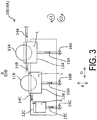
- FIG. 3 a detailed configuration of the cleaning unit 10, which is a main component of the inkjet printer 1 of this example, will be described in detail with reference to FIG. 3 .
- arrows in FIG. 3 indicate directions in which the cleaning liquid L flows.
- a cleaning unit 10A of this example is provided with the first brush 11A for cleaning the transporting belt 5 and the first cleaning liquid tank 12A that stores the cleaning liquid L with which the first brush 11A is impregnated.
- the cleaning unit 10A is provided with the second brush 11B for cleaning the transporting belt 5 and the second cleaning liquid tank 12B that stores the cleaning liquid L with which the second brush 11B is impregnated.
- a cleaning liquid flow path 14A is connected to a supply source of the cleaning liquid L, such as a tap, and is a supply path for supplying the cleaning liquid L from the supply source to the cleaning unit 10A. Then, the first cleaning liquid tank 12A is configured to be able to receive the supply of the cleaning liquid L from the cleaning liquid flow path 14A. Further, the first cleaning liquid tank 12A is configured to be able to discharge the cleaning liquid L from a cleaning liquid flow path 14B and from a discharge path 15A provided with an opening/closing portion 16A.
- the second cleaning liquid tank 12B is provided at a position that is displaced from the first cleaning liquid tank 12A in the horizontal direction D and that is lower than the first cleaning liquid tank 12A in the vertical direction E. Then, the second cleaning liquid tank 12B is configured to be able to receive the supply of the cleaning liquid L from the cleaning liquid flow path 14B. Further, the second cleaning liquid tank 12B is configured to be able to discharge the cleaning liquid L from a cleaning liquid flow path 14C and from a discharge path 15B provided with an opening/closing portion 16B.
- a third cleaning liquid tank 12C is provided at a position that is displaced from the second cleaning liquid tank 12B in the horizontal direction D and that is lower than the second cleaning liquid tank 1 B in the vertical direction E. Then, the third cleaning liquid tank 12C is configured to be able to receive the supply of the cleaning liquid L from the cleaning liquid flow path 14C. Further, the third cleaning liquid tank 12C is configured to be able to discharge the cleaning liquid L from a discharge path 15C provided with an opening/closing portion 16C. The opening/closing portion 16C is specifically a valve.
- the third cleaning liquid tank 12C serves as a buffer region that prevents the cleaning liquid L from overflowing from the cleaning unit 10.
- the supply source of the cleaning liquid L basically stops supplying the cleaning liquid L once a sufficient amount of the cleaning liquid L has been stored in the first cleaning liquid tank 12A and the second cleaning liquid tank 12B. However, if the cleaning liquid L overflows from the second cleaning liquid tank 12B for whatever reason, the cleaning liquid L is stored in the third cleaning liquid tank 12C that serves as the buffer region. In the inkjet printer 1, normally, the opening/closing portion 16C is closed, and the discharge path 15C is in a closed state. In this way, the cleaning liquid L overflowing from the second cleaning liquid tank 12B is stored in the third cleaning liquid tank 12C.
- the discharge path 15C is caused to be in an open state, and the cleaning liquid L stored in the third cleaning liquid tank 12C is discharged from the discharge path 15C.
- a user may be notified when the cleaning liquid L stored in the third cleaning liquid tank 12C exceeds a predetermined amount, and may be prompted to discharge the cleaning liquid L stored in the third cleaning liquid tank 12C.
- a configuration may be adopted in which the third cleaning liquid tank 12C serving as the buffer region is not provided.
- the inkjet printer 1 of this example is provided with the endless transporting belt 5 that transports the medium M in the transport direction A by supporting the medium M and rotating, the head 8 that ejects ink onto the medium M supported by the transporting belt 5, and the cleaning unit 10.
- the cleaning unit 10 includes the first brush 11A for cleaning the transporting belt 5, the first cleaning liquid tank 12A that stores the cleaning liquid L with which the first brush 11A is impregnated, the second brush 11B for cleaning the transporting belt 5, and the second cleaning liquid tank 12B that stores the cleaning liquid L with which the second brush 11B is impregnated.
- the second cleaning liquid tank 12B is disposed at a position that is lower than the first cleaning liquid tank 12A in the vertical direction E.
- the cleaning unit 10 has a configuration in which the cleaning liquid L discharged from the first cleaning liquid tank 12A is supplied to the second cleaning liquid tank 12B. Since the inkjet printer 1 of this example has such a configuration, the inkjet printer 1 is configured to be able to supply the cleaning liquid L from the first cleaning liquid tank 12A to the second cleaning liquid tank 12B using gravity. In other words, it is not necessary to extend the supply path from the supply source of the cleaning liquid L to the second cleaning liquid tank 12B. Thus, the configuration of the flow path of the cleaning liquid L is simplified compared to a case in which supply paths for the cleaning liquid are individually provided from the supply source of the cleaning liquid L to each of the cleaning liquid tanks.
- the first cleaning liquid tank 12A and the second cleaning liquid tank 12B are configured respectively by individual tanks separated from each other.
- the cleaning unit 10A of this example has the cleaning liquid flow path 14B that supplies the cleaning liquid L discharged from the first cleaning liquid tank 12A to the second cleaning liquid tank 12B.
- the position, size, and the like of each of the first cleaning liquid tank 12A and the second cleaning liquid tank 12B can be optimized.
- the cleaning liquid L can be supplied from the first cleaning liquid tank 12A to the second cleaning liquid tank 12B without spillage of the cleaning liquid L.
- the configuration is not limited to such a configuration, and may be a configuration in which the cleaning liquid flow path 14B is not provided, and the cleaning liquid L flows directly from the first cleaning liquid tank 12A down to the second cleaning liquid tank 12B.
- the cleaning unit 10 is configured so that the set of the first brush 11A and the first cleaning liquid tank 12A and the set of the second brush 11B and the second cleaning liquid tank 12B are each configured to be individually movable in the horizontal direction D and the vertical direction E.
- the first cleaning liquid tank 12A and the second cleaning liquid tank 12B are configured to be movable independently of each other.
- the inkjet printer 1 of this example is configured to be able to easily optimize the position of each of the first cleaning liquid tank 12A and the second cleaning liquid tank 12B relative to the transporting belt 5, for example, even when the inclination angle of the support surface 5a of the inclined transporting belt 5 changes as a result of changing the position of the adjustment roller 6.
- the first cleaning liquid tank 12A includes the discharge path 15A that serves as a first discharge path for discharging the cleaning liquid L stored in the first cleaning liquid tank 12A without supplying the cleaning liquid L to the second cleaning liquid tank 12B, and the opening/closing portion 16A that serves as a first opening/closing portion for opening and closing the discharge path 15A.
- the second cleaning liquid tank 12B includes the discharge path 15B as a second discharge path for discharging the cleaning liquid L stored in the second cleaning liquid tank 12B, and the opening/closing portion 16B that serves as a second opening/closing portion for opening and closing the discharge path 15B.
- the opening/closing portion 16A and the opening/closing portion 16B are specifically valves.
- the opening/closing portion 16A is closed to cause the discharge path 15A to be in a closed state
- the opening/closing portion 16B is closed to cause the discharge path 15B to be in a closed state.
- the cleaning liquid L can be suitably stored in the first cleaning liquid tank 12A and the second cleaning liquid tank 12B.
- the opening/closing portion 16A is opened to cause the discharge path 15A to be in an open state
- the opening/closing portion 16B is opened to cause the discharge path 15B to be in an open state.
- the cleaning liquid L can be suitably discharged from the first cleaning liquid tank 12A and the second cleaning liquid tank 12B.
- the inkjet printer 1 of this example can easily store the cleaning liquid L in the first cleaning liquid tank 12A and the second cleaning liquid tank 12B when the inkjet printer 1 is used, and can easily discharge the cleaning liquid L from the first cleaning liquid tank 12A and the second cleaning liquid tank 12B when the inkjet printer 1 is not used.
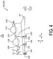
- FIG. 4 is a schematic side view illustrating the cleaning unit 10 in the inkjet printer 1 of this example, and is a diagram corresponding to FIG. 3 illustrating the inkjet printer 1 according to Example 1.
- the inkjet printer 1 of this example has the same configuration as that of the inkjet printer 1 of Example 1 apart from the cleaning unit 10, and a description of common portions of the configuration, such as portions other than the cleaning unit 10, is therefore omitted here.
- the structural members common to those in Example 1 described above are denoted by the same reference numerals, and a detailed description thereof is omitted.
- a cleaning unit 10B of this example is provided with the first brush 11A for cleaning the transporting belt 5, and the first cleaning liquid tank 12A that stores the cleaning liquid L with which the first brush 11A is impregnated.
- the cleaning unit 10A is provided with the second brush 11B for cleaning the transporting belt 5 and the second cleaning liquid tank 12B that stores the cleaning liquid L with which the second brush 11B is impregnated.
- the first cleaning liquid tank 12A and the second cleaning liquid tank 12B are simply separated by a partition 17 and are integrally formed.
- the first cleaning liquid tank 12A and the second cleaning liquid tank 12B are formed so as to be adjacent to each other while sharing the partition 17.
- the first cleaning liquid tank 12A is configured to be able to receive the supply of the cleaning liquid L from a cleaning liquid flow path 14D. Further, the first cleaning liquid tank 12A is configured so as to be able to discharge the cleaning liquid L from an edge thereof closer to the partition 17, that is, from the edge thereof located downstream in the direction in which the cleaning liquid L flows. Furthermore, the first cleaning liquid tank 12A is configured to be able to discharge the cleaning liquid L from a discharge path 15D that serves as the first discharge path and that is provided with an opening/closing portion 16D that serves as the first opening/closing portion.
- the second cleaning liquid tank 12B is provided at a position that is adjacent to the first cleaning liquid tank 12A in the horizontal direction D and that is lower than the first cleaning liquid tank 12A in the vertical direction E. Then, the second cleaning liquid tank 12B is configured to be able to receive the supply of the cleaning liquid L from the edge of the first cleaning liquid tank 12A closer to the partition 17. Further, the second cleaning liquid tank 12B is configured to be able to discharge the cleaning liquid L from an edge thereof located opposite to the partition part 17, that is, from the edge thereof located downstream in the direction in which the cleaning liquid L flows. Furthermore, the second cleaning liquid tank 12B is configured to be able to discharge the cleaning liquid L from a discharge path 15E that serves as the second discharge path and that is provided with an opening/closing portion 16E that serves as the second opening/closing portion.
- the opening/closing portion 16D and the opening/closing portion 16E are specifically valves.
- the opening/closing portion 16D is closed so as to cause the discharge path 15D to be in a closed state
- the opening/closing portion 16E is closed so as to cause the discharge path 15E to be in a closed state.
- the cleaning liquid L can be suitably stored in the first cleaning liquid tank 12A and the second cleaning liquid tank 12B.
- the opening/closing portion 16D is opened to cause the discharge path 15D to be in an open state
- the opening/closing portion 16E is opened to cause the discharge path 15E to be in an open state.
- the cleaning liquid L can be suitably discharged from the first cleaning liquid tank 12A and the second cleaning liquid tank 12B.
- the buffer region is provided at a position located further downstream than the second cleaning liquid tank 12B in the direction in which the cleaning liquid L flows.
- a discharge path 15F provided with an opening/closing portion 16F is provided in the buffer region, and the cleaning liquid L can be discharged from the discharge path 15F.
- the opening/closing portion 16F is specifically a valve.
- the supply source of the cleaning liquid L such as the tap, basically stops supplying the cleaning liquid L once a sufficient amount of the cleaning liquid L has been stored in the first cleaning liquid tank 12A and the second cleaning liquid tank 12B. However, if the cleaning liquid L overflows from the second cleaning liquid tank 12B for whatever reason, the cleaning liquid L is stored in the buffer region.
- the opening/closing portion 16F is closed, and the discharge path 15F is in a closed state. In this way, the cleaning liquid L overflowing from the second cleaning liquid tank 12B is stored in the buffer region. Then, by opening the opening/closing portion 16F at any given timing, the discharge path 15F is caused to be in an open state, and the cleaning liquid L stored in the buffer region is discharged from the discharge path 15F. For example, by providing a liquid level sensor or the like in the buffer region, the user may be notified when the cleaning liquid L stored in the buffer region exceeds a predetermined amount and may be prompted to discharge the cleaning liquid L stored in the buffer region. Note that a configuration may be adopted in which the buffer region is not provided.
- the cleaning unit 10B of this example is provided with the blade portion 13 that wipes off the cleaning liquid L attached to the transporting belt 5 as a result of bringing the first brush 11A and the second brush 11B into contact with the transporting belt 5.
- the set of the first brush 11A and the first cleaning liquid tank 12A, and the set of the second brush 11B and the second cleaning liquid tank 12B are not respectively configured to be individually movable in the horizontal direction D and the vertical direction E.
- the cleaning unit 10B of this example includes a rotating shaft 18 and is configured to be able to rotate integrally in the rotation direction C1 and the rotation direction C2 around the rotating shaft 18.
- the first cleaning liquid tank 12A and the second cleaning liquid tank 12B are formed by being partitioned by the partition 17, which partitions a single tank into a plurality of compartments. In this way, the inkjet printer 1 of this example easily forms the first cleaning liquid tank 12A and the second cleaning liquid tank 12B by partitioning the single tank.
- the first cleaning liquid tank 12A and the second cleaning liquid tank 12B are configured to be movable integrally. In this way, in the inkjet printer 1 of this example, since the first cleaning liquid tank 12A and the second cleaning liquid tank 12B are movable integrally, the positions of the first cleaning liquid tank 12A and the second cleaning liquid tank 12B relative to the transporting belt 5 can be adjusted integrally.
Landscapes
- Ink Jet (AREA)
- Handling Of Sheets (AREA)
- Feeding Of Articles By Means Other Than Belts Or Rollers (AREA)
Applications Claiming Priority (1)
| Application Number | Priority Date | Filing Date | Title |
|---|---|---|---|
| JP2019007738A JP7310147B2 (ja) | 2019-01-21 | 2019-01-21 | インクジェットプリンター |
Publications (2)
| Publication Number | Publication Date |
|---|---|
| EP3683065A1 true EP3683065A1 (fr) | 2020-07-22 |
| EP3683065B1 EP3683065B1 (fr) | 2022-11-16 |
Family
ID=69187560
Family Applications (1)
| Application Number | Title | Priority Date | Filing Date |
|---|---|---|---|
| EP20152948.4A Active EP3683065B1 (fr) | 2019-01-21 | 2020-01-21 | Imprimante à jet d'encre avec unité de nettoyage |
Country Status (5)
| Country | Link |
|---|---|
| US (1) | US11040542B2 (fr) |
| EP (1) | EP3683065B1 (fr) |
| JP (1) | JP7310147B2 (fr) |
| CN (1) | CN111452504B (fr) |
| ES (1) | ES2934511T3 (fr) |
Families Citing this family (1)
| Publication number | Priority date | Publication date | Assignee | Title |
|---|---|---|---|---|
| US20220242044A1 (en) * | 2019-05-23 | 2022-08-04 | General Electric Company | Cleaning systems for additive manufacturing apparatuses and methods for using the same |
Citations (6)
| Publication number | Priority date | Publication date | Assignee | Title |
|---|---|---|---|---|
| US20050110856A1 (en) * | 2003-11-20 | 2005-05-26 | Canon Kabushiki Kaisha | Ink-jet recording method and ink-jet recording apparatus |
| JP2006272834A (ja) | 2005-03-30 | 2006-10-12 | Konica Minolta Holdings Inc | インクジェット記録装置 |
| US20080218550A1 (en) * | 2007-03-07 | 2008-09-11 | Kyocera Mita Corporation | Inkjet recording apparatus |
| US20160355037A1 (en) * | 2014-02-21 | 2016-12-08 | Seiko Epson Corporation | Recording apparatus, and cleaning method of recording apparatus |
| EP3213924A1 (fr) * | 2016-03-01 | 2017-09-06 | Seiko Epson Corporation | Imprimante |
| JP2019007738A (ja) | 2017-06-20 | 2019-01-17 | 株式会社東芝 | 使用済み燃料貯蔵ラック |
Family Cites Families (6)
| Publication number | Priority date | Publication date | Assignee | Title |
|---|---|---|---|---|
| JPS4719267U (fr) * | 1971-04-07 | 1972-11-04 | ||
| JP3655421B2 (ja) * | 1997-03-27 | 2005-06-02 | 富士写真フイルム株式会社 | 洗浄装置及び現像処理装置用洗浄装置 |
| JP4293034B2 (ja) * | 2004-03-30 | 2009-07-08 | コニカミノルタホールディングス株式会社 | ベルト式搬送装置及び画像記録装置 |
| JP2013046981A (ja) | 2011-08-29 | 2013-03-07 | Fujifilm Corp | ドラム清掃装置、塗布装置及びインクジェット記録装置 |
| JP6331249B2 (ja) * | 2013-01-16 | 2018-05-30 | セイコーエプソン株式会社 | ベルト洗浄装置及び記録装置 |
| EP2756958B1 (fr) * | 2013-01-16 | 2019-05-15 | Seiko Epson Corporation | Appareil de nettoyage de courroie et appareil d'enregistrement |
-
2019
- 2019-01-21 JP JP2019007738A patent/JP7310147B2/ja active Active
-
2020
- 2020-01-17 US US16/745,745 patent/US11040542B2/en active Active
- 2020-01-17 CN CN202010055583.3A patent/CN111452504B/zh active Active
- 2020-01-21 EP EP20152948.4A patent/EP3683065B1/fr active Active
- 2020-01-21 ES ES20152948T patent/ES2934511T3/es active Active
Patent Citations (6)
| Publication number | Priority date | Publication date | Assignee | Title |
|---|---|---|---|---|
| US20050110856A1 (en) * | 2003-11-20 | 2005-05-26 | Canon Kabushiki Kaisha | Ink-jet recording method and ink-jet recording apparatus |
| JP2006272834A (ja) | 2005-03-30 | 2006-10-12 | Konica Minolta Holdings Inc | インクジェット記録装置 |
| US20080218550A1 (en) * | 2007-03-07 | 2008-09-11 | Kyocera Mita Corporation | Inkjet recording apparatus |
| US20160355037A1 (en) * | 2014-02-21 | 2016-12-08 | Seiko Epson Corporation | Recording apparatus, and cleaning method of recording apparatus |
| EP3213924A1 (fr) * | 2016-03-01 | 2017-09-06 | Seiko Epson Corporation | Imprimante |
| JP2019007738A (ja) | 2017-06-20 | 2019-01-17 | 株式会社東芝 | 使用済み燃料貯蔵ラック |
Also Published As
| Publication number | Publication date |
|---|---|
| EP3683065B1 (fr) | 2022-11-16 |
| CN111452504B (zh) | 2023-02-28 |
| ES2934511T3 (es) | 2023-02-22 |
| JP2020117324A (ja) | 2020-08-06 |
| JP7310147B2 (ja) | 2023-07-19 |
| US11040542B2 (en) | 2021-06-22 |
| CN111452504A (zh) | 2020-07-28 |
| US20200230962A1 (en) | 2020-07-23 |
Similar Documents
| Publication | Publication Date | Title |
|---|---|---|
| JP7114961B2 (ja) | 印刷装置及び媒体の搬送方法 | |
| EP3683065B1 (fr) | Imprimante à jet d'encre avec unité de nettoyage | |
| JP2018001443A (ja) | 印刷装置および印刷方法 | |
| US10730325B2 (en) | Liquid ejecting apparatus and adjustment part | |
| US11648786B2 (en) | Recording device and method for reversely transporting recording medium | |
| EP3363640B1 (fr) | Appareil de décharge de liquide et procédé de nettoyage de filtres | |
| US9868307B2 (en) | Printing apparatus and printing method | |
| US11376870B2 (en) | Liquid ejecting device having recesses and protrusions on contact surface between transport belt and rollers of liquid ejecting device | |
| EP3196039B1 (fr) | Appareil d'impression et procédé d'impression | |
| JP7404757B2 (ja) | 液体吐出装置 | |
| EP3686137B1 (fr) | Dispositif de transport, appareil d'impression et procédé de réglage d'unité d'alimentation | |
| EP3208090B1 (fr) | Appareil d'impression et procédé d'impression | |
| EP4375078A1 (fr) | Dispositif de transport et appareil d'éjection de liquide | |
| JP6988163B2 (ja) | キャリッジ及び液体吐出装置 | |
| EP3263346B1 (fr) | Unité d'électrovanne, imprimante et procédé d'impression | |
| JP2018176502A (ja) | 液体吐出装置及び液体の供給方法 | |
| JP2020090356A (ja) | 液体吐出装置 |
Legal Events
| Date | Code | Title | Description |
|---|---|---|---|
| PUAI | Public reference made under article 153(3) epc to a published international application that has entered the european phase |
Free format text: ORIGINAL CODE: 0009012 |
|
| STAA | Information on the status of an ep patent application or granted ep patent |
Free format text: STATUS: THE APPLICATION HAS BEEN PUBLISHED |
|
| AK | Designated contracting states |
Kind code of ref document: A1 Designated state(s): AL AT BE BG CH CY CZ DE DK EE ES FI FR GB GR HR HU IE IS IT LI LT LU LV MC MK MT NL NO PL PT RO RS SE SI SK SM TR |
|
| AX | Request for extension of the european patent |
Extension state: BA ME |
|
| STAA | Information on the status of an ep patent application or granted ep patent |
Free format text: STATUS: REQUEST FOR EXAMINATION WAS MADE |
|
| 17P | Request for examination filed |
Effective date: 20201123 |
|
| RBV | Designated contracting states (corrected) |
Designated state(s): AL AT BE BG CH CY CZ DE DK EE ES FI FR GB GR HR HU IE IS IT LI LT LU LV MC MK MT NL NO PL PT RO RS SE SI SK SM TR |
|
| GRAP | Despatch of communication of intention to grant a patent |
Free format text: ORIGINAL CODE: EPIDOSNIGR1 |
|
| STAA | Information on the status of an ep patent application or granted ep patent |
Free format text: STATUS: GRANT OF PATENT IS INTENDED |
|
| INTG | Intention to grant announced |
Effective date: 20220613 |
|
| GRAS | Grant fee paid |
Free format text: ORIGINAL CODE: EPIDOSNIGR3 |
|
| GRAA | (expected) grant |
Free format text: ORIGINAL CODE: 0009210 |
|
| STAA | Information on the status of an ep patent application or granted ep patent |
Free format text: STATUS: THE PATENT HAS BEEN GRANTED |
|
| AK | Designated contracting states |
Kind code of ref document: B1 Designated state(s): AL AT BE BG CH CY CZ DE DK EE ES FI FR GB GR HR HU IE IS IT LI LT LU LV MC MK MT NL NO PL PT RO RS SE SI SK SM TR |
|
| REG | Reference to a national code |
Ref country code: GB Ref legal event code: FG4D |
|
| REG | Reference to a national code |
Ref country code: CH Ref legal event code: EP |
|
| REG | Reference to a national code |
Ref country code: IE Ref legal event code: FG4D |
|
| REG | Reference to a national code |
Ref country code: DE Ref legal event code: R096 Ref document number: 602020006228 Country of ref document: DE |
|
| REG | Reference to a national code |
Ref country code: AT Ref legal event code: REF Ref document number: 1531551 Country of ref document: AT Kind code of ref document: T Effective date: 20221215 |
|
| REG | Reference to a national code |
Ref country code: ES Ref legal event code: FG2A Ref document number: 2934511 Country of ref document: ES Kind code of ref document: T3 Effective date: 20230222 |
|
| REG | Reference to a national code |
Ref country code: LT Ref legal event code: MG9D |
|
| REG | Reference to a national code |
Ref country code: NL Ref legal event code: MP Effective date: 20221116 |
|
| REG | Reference to a national code |
Ref country code: AT Ref legal event code: MK05 Ref document number: 1531551 Country of ref document: AT Kind code of ref document: T Effective date: 20221116 |
|
| PG25 | Lapsed in a contracting state [announced via postgrant information from national office to epo] |
Ref country code: SE Free format text: LAPSE BECAUSE OF FAILURE TO SUBMIT A TRANSLATION OF THE DESCRIPTION OR TO PAY THE FEE WITHIN THE PRESCRIBED TIME-LIMIT Effective date: 20221116 Ref country code: PT Free format text: LAPSE BECAUSE OF FAILURE TO SUBMIT A TRANSLATION OF THE DESCRIPTION OR TO PAY THE FEE WITHIN THE PRESCRIBED TIME-LIMIT Effective date: 20230316 Ref country code: NO Free format text: LAPSE BECAUSE OF FAILURE TO SUBMIT A TRANSLATION OF THE DESCRIPTION OR TO PAY THE FEE WITHIN THE PRESCRIBED TIME-LIMIT Effective date: 20230216 Ref country code: LT Free format text: LAPSE BECAUSE OF FAILURE TO SUBMIT A TRANSLATION OF THE DESCRIPTION OR TO PAY THE FEE WITHIN THE PRESCRIBED TIME-LIMIT Effective date: 20221116 Ref country code: FI Free format text: LAPSE BECAUSE OF FAILURE TO SUBMIT A TRANSLATION OF THE DESCRIPTION OR TO PAY THE FEE WITHIN THE PRESCRIBED TIME-LIMIT Effective date: 20221116 Ref country code: AT Free format text: LAPSE BECAUSE OF FAILURE TO SUBMIT A TRANSLATION OF THE DESCRIPTION OR TO PAY THE FEE WITHIN THE PRESCRIBED TIME-LIMIT Effective date: 20221116 |
|
| PG25 | Lapsed in a contracting state [announced via postgrant information from national office to epo] |
Ref country code: RS Free format text: LAPSE BECAUSE OF FAILURE TO SUBMIT A TRANSLATION OF THE DESCRIPTION OR TO PAY THE FEE WITHIN THE PRESCRIBED TIME-LIMIT Effective date: 20221116 Ref country code: PL Free format text: LAPSE BECAUSE OF FAILURE TO SUBMIT A TRANSLATION OF THE DESCRIPTION OR TO PAY THE FEE WITHIN THE PRESCRIBED TIME-LIMIT Effective date: 20221116 Ref country code: LV Free format text: LAPSE BECAUSE OF FAILURE TO SUBMIT A TRANSLATION OF THE DESCRIPTION OR TO PAY THE FEE WITHIN THE PRESCRIBED TIME-LIMIT Effective date: 20221116 Ref country code: IS Free format text: LAPSE BECAUSE OF FAILURE TO SUBMIT A TRANSLATION OF THE DESCRIPTION OR TO PAY THE FEE WITHIN THE PRESCRIBED TIME-LIMIT Effective date: 20230316 Ref country code: HR Free format text: LAPSE BECAUSE OF FAILURE TO SUBMIT A TRANSLATION OF THE DESCRIPTION OR TO PAY THE FEE WITHIN THE PRESCRIBED TIME-LIMIT Effective date: 20221116 Ref country code: GR Free format text: LAPSE BECAUSE OF FAILURE TO SUBMIT A TRANSLATION OF THE DESCRIPTION OR TO PAY THE FEE WITHIN THE PRESCRIBED TIME-LIMIT Effective date: 20230217 |
|
| PGFP | Annual fee paid to national office [announced via postgrant information from national office to epo] |
Ref country code: IT Payment date: 20230131 Year of fee payment: 4 |
|
| PG25 | Lapsed in a contracting state [announced via postgrant information from national office to epo] |
Ref country code: NL Free format text: LAPSE BECAUSE OF FAILURE TO SUBMIT A TRANSLATION OF THE DESCRIPTION OR TO PAY THE FEE WITHIN THE PRESCRIBED TIME-LIMIT Effective date: 20221116 |
|
| PG25 | Lapsed in a contracting state [announced via postgrant information from national office to epo] |
Ref country code: SM Free format text: LAPSE BECAUSE OF FAILURE TO SUBMIT A TRANSLATION OF THE DESCRIPTION OR TO PAY THE FEE WITHIN THE PRESCRIBED TIME-LIMIT Effective date: 20221116 Ref country code: RO Free format text: LAPSE BECAUSE OF FAILURE TO SUBMIT A TRANSLATION OF THE DESCRIPTION OR TO PAY THE FEE WITHIN THE PRESCRIBED TIME-LIMIT Effective date: 20221116 Ref country code: EE Free format text: LAPSE BECAUSE OF FAILURE TO SUBMIT A TRANSLATION OF THE DESCRIPTION OR TO PAY THE FEE WITHIN THE PRESCRIBED TIME-LIMIT Effective date: 20221116 Ref country code: DK Free format text: LAPSE BECAUSE OF FAILURE TO SUBMIT A TRANSLATION OF THE DESCRIPTION OR TO PAY THE FEE WITHIN THE PRESCRIBED TIME-LIMIT Effective date: 20221116 Ref country code: CZ Free format text: LAPSE BECAUSE OF FAILURE TO SUBMIT A TRANSLATION OF THE DESCRIPTION OR TO PAY THE FEE WITHIN THE PRESCRIBED TIME-LIMIT Effective date: 20221116 |
|
| REG | Reference to a national code |
Ref country code: DE Ref legal event code: R119 Ref document number: 602020006228 Country of ref document: DE |
|
| PG25 | Lapsed in a contracting state [announced via postgrant information from national office to epo] |
Ref country code: SK Free format text: LAPSE BECAUSE OF FAILURE TO SUBMIT A TRANSLATION OF THE DESCRIPTION OR TO PAY THE FEE WITHIN THE PRESCRIBED TIME-LIMIT Effective date: 20221116 Ref country code: AL Free format text: LAPSE BECAUSE OF FAILURE TO SUBMIT A TRANSLATION OF THE DESCRIPTION OR TO PAY THE FEE WITHIN THE PRESCRIBED TIME-LIMIT Effective date: 20221116 |
|
| REG | Reference to a national code |
Ref country code: CH Ref legal event code: PL |
|
| PLBE | No opposition filed within time limit |
Free format text: ORIGINAL CODE: 0009261 |
|
| STAA | Information on the status of an ep patent application or granted ep patent |
Free format text: STATUS: NO OPPOSITION FILED WITHIN TIME LIMIT |
|
| PG25 | Lapsed in a contracting state [announced via postgrant information from national office to epo] |
Ref country code: LU Free format text: LAPSE BECAUSE OF NON-PAYMENT OF DUE FEES Effective date: 20230121 |
|
| REG | Reference to a national code |
Ref country code: BE Ref legal event code: MM Effective date: 20230131 |
|
| 26N | No opposition filed |
Effective date: 20230817 |
|
| PG25 | Lapsed in a contracting state [announced via postgrant information from national office to epo] |
Ref country code: LI Free format text: LAPSE BECAUSE OF NON-PAYMENT OF DUE FEES Effective date: 20230131 Ref country code: DE Free format text: LAPSE BECAUSE OF NON-PAYMENT OF DUE FEES Effective date: 20230801 Ref country code: CH Free format text: LAPSE BECAUSE OF NON-PAYMENT OF DUE FEES Effective date: 20230131 |
|
| PG25 | Lapsed in a contracting state [announced via postgrant information from national office to epo] |
Ref country code: SI Free format text: LAPSE BECAUSE OF FAILURE TO SUBMIT A TRANSLATION OF THE DESCRIPTION OR TO PAY THE FEE WITHIN THE PRESCRIBED TIME-LIMIT Effective date: 20221116 Ref country code: FR Free format text: LAPSE BECAUSE OF NON-PAYMENT OF DUE FEES Effective date: 20230131 Ref country code: BE Free format text: LAPSE BECAUSE OF NON-PAYMENT OF DUE FEES Effective date: 20230131 |
|
| PG25 | Lapsed in a contracting state [announced via postgrant information from national office to epo] |
Ref country code: IE Free format text: LAPSE BECAUSE OF NON-PAYMENT OF DUE FEES Effective date: 20230121 |
|
| PGFP | Annual fee paid to national office [announced via postgrant information from national office to epo] |
Ref country code: ES Payment date: 20240227 Year of fee payment: 5 |