EP3682837B1 - System und verfahren zur lösbaren kupplung in einem gelenkarm - Google Patents
System und verfahren zur lösbaren kupplung in einem gelenkarm Download PDFInfo
- Publication number
- EP3682837B1 EP3682837B1 EP20161333.8A EP20161333A EP3682837B1 EP 3682837 B1 EP3682837 B1 EP 3682837B1 EP 20161333 A EP20161333 A EP 20161333A EP 3682837 B1 EP3682837 B1 EP 3682837B1
- Authority
- EP
- European Patent Office
- Prior art keywords
- joint
- articulated arm
- state
- locked state
- float
- Prior art date
- Legal status (The legal status is an assumption and is not a legal conclusion. Google has not performed a legal analysis and makes no representation as to the accuracy of the status listed.)
- Active
Links
- 238000000034 method Methods 0.000 title claims description 49
- 239000002131 composite material Substances 0.000 claims description 4
- 230000008569 process Effects 0.000 description 24
- 230000006378 damage Effects 0.000 description 11
- 239000012636 effector Substances 0.000 description 11
- 208000027418 Wounds and injury Diseases 0.000 description 6
- 230000004913 activation Effects 0.000 description 6
- 238000010586 diagram Methods 0.000 description 6
- 208000014674 injury Diseases 0.000 description 6
- 230000007246 mechanism Effects 0.000 description 5
- 230000002776 aggregation Effects 0.000 description 4
- 238000004220 aggregation Methods 0.000 description 4
- 230000003213 activating effect Effects 0.000 description 3
- 230000005484 gravity Effects 0.000 description 3
- 230000004048 modification Effects 0.000 description 3
- 238000012986 modification Methods 0.000 description 3
- 230000001052 transient effect Effects 0.000 description 3
- 238000003491 array Methods 0.000 description 2
- 230000008859 change Effects 0.000 description 2
- 230000008878 coupling Effects 0.000 description 2
- 238000010168 coupling process Methods 0.000 description 2
- 238000005859 coupling reaction Methods 0.000 description 2
- 238000009499 grossing Methods 0.000 description 2
- 238000012544 monitoring process Methods 0.000 description 2
- 230000003287 optical effect Effects 0.000 description 2
- 230000003068 static effect Effects 0.000 description 2
- 230000008901 benefit Effects 0.000 description 1
- 238000013016 damping Methods 0.000 description 1
- 230000001419 dependent effect Effects 0.000 description 1
- 238000013461 design Methods 0.000 description 1
- 230000004069 differentiation Effects 0.000 description 1
- 230000007613 environmental effect Effects 0.000 description 1
- 230000006870 function Effects 0.000 description 1
- 239000011521 glass Substances 0.000 description 1
- 238000003384 imaging method Methods 0.000 description 1
- 238000001990 intravenous administration Methods 0.000 description 1
- QSHDDOUJBYECFT-UHFFFAOYSA-N mercury Chemical compound [Hg] QSHDDOUJBYECFT-UHFFFAOYSA-N 0.000 description 1
- 229910052753 mercury Inorganic materials 0.000 description 1
- 239000000203 mixture Substances 0.000 description 1
- 238000012545 processing Methods 0.000 description 1
- 230000004044 response Effects 0.000 description 1
- 238000006467 substitution reaction Methods 0.000 description 1
Images
Classifications
-
- A—HUMAN NECESSITIES
- A61—MEDICAL OR VETERINARY SCIENCE; HYGIENE
- A61B—DIAGNOSIS; SURGERY; IDENTIFICATION
- A61B34/00—Computer-aided surgery; Manipulators or robots specially adapted for use in surgery
- A61B34/30—Surgical robots
-
- A—HUMAN NECESSITIES
- A61—MEDICAL OR VETERINARY SCIENCE; HYGIENE
- A61B—DIAGNOSIS; SURGERY; IDENTIFICATION
- A61B34/00—Computer-aided surgery; Manipulators or robots specially adapted for use in surgery
- A61B34/70—Manipulators specially adapted for use in surgery
-
- B—PERFORMING OPERATIONS; TRANSPORTING
- B25—HAND TOOLS; PORTABLE POWER-DRIVEN TOOLS; MANIPULATORS
- B25J—MANIPULATORS; CHAMBERS PROVIDED WITH MANIPULATION DEVICES
- B25J13/00—Controls for manipulators
- B25J13/08—Controls for manipulators by means of sensing devices, e.g. viewing or touching devices
- B25J13/085—Force or torque sensors
-
- B—PERFORMING OPERATIONS; TRANSPORTING
- B25—HAND TOOLS; PORTABLE POWER-DRIVEN TOOLS; MANIPULATORS
- B25J—MANIPULATORS; CHAMBERS PROVIDED WITH MANIPULATION DEVICES
- B25J13/00—Controls for manipulators
- B25J13/08—Controls for manipulators by means of sensing devices, e.g. viewing or touching devices
- B25J13/088—Controls for manipulators by means of sensing devices, e.g. viewing or touching devices with position, velocity or acceleration sensors
-
- B—PERFORMING OPERATIONS; TRANSPORTING
- B25—HAND TOOLS; PORTABLE POWER-DRIVEN TOOLS; MANIPULATORS
- B25J—MANIPULATORS; CHAMBERS PROVIDED WITH MANIPULATION DEVICES
- B25J9/00—Programme-controlled manipulators
- B25J9/16—Programme controls
- B25J9/1679—Programme controls characterised by the tasks executed
- B25J9/1689—Teleoperation
-
- B—PERFORMING OPERATIONS; TRANSPORTING
- B25—HAND TOOLS; PORTABLE POWER-DRIVEN TOOLS; MANIPULATORS
- B25J—MANIPULATORS; CHAMBERS PROVIDED WITH MANIPULATION DEVICES
- B25J9/00—Programme-controlled manipulators
- B25J9/16—Programme controls
- B25J9/1694—Programme controls characterised by use of sensors other than normal servo-feedback from position, speed or acceleration sensors, perception control, multi-sensor controlled systems, sensor fusion
-
- A—HUMAN NECESSITIES
- A61—MEDICAL OR VETERINARY SCIENCE; HYGIENE
- A61B—DIAGNOSIS; SURGERY; IDENTIFICATION
- A61B18/00—Surgical instruments, devices or methods for transferring non-mechanical forms of energy to or from the body
- A61B2018/00636—Sensing and controlling the application of energy
- A61B2018/00666—Sensing and controlling the application of energy using a threshold value
- A61B2018/00672—Sensing and controlling the application of energy using a threshold value lower
-
- A—HUMAN NECESSITIES
- A61—MEDICAL OR VETERINARY SCIENCE; HYGIENE
- A61B—DIAGNOSIS; SURGERY; IDENTIFICATION
- A61B18/00—Surgical instruments, devices or methods for transferring non-mechanical forms of energy to or from the body
- A61B2018/00636—Sensing and controlling the application of energy
- A61B2018/00666—Sensing and controlling the application of energy using a threshold value
- A61B2018/00678—Sensing and controlling the application of energy using a threshold value upper
-
- A—HUMAN NECESSITIES
- A61—MEDICAL OR VETERINARY SCIENCE; HYGIENE
- A61B—DIAGNOSIS; SURGERY; IDENTIFICATION
- A61B34/00—Computer-aided surgery; Manipulators or robots specially adapted for use in surgery
- A61B34/30—Surgical robots
- A61B2034/305—Details of wrist mechanisms at distal ends of robotic arms
-
- A—HUMAN NECESSITIES
- A61—MEDICAL OR VETERINARY SCIENCE; HYGIENE
- A61B—DIAGNOSIS; SURGERY; IDENTIFICATION
- A61B90/00—Instruments, implements or accessories specially adapted for surgery or diagnosis and not covered by any of the groups A61B1/00 - A61B50/00, e.g. for luxation treatment or for protecting wound edges
- A61B90/03—Automatic limiting or abutting means, e.g. for safety
- A61B2090/033—Abutting means, stops, e.g. abutting on tissue or skin
- A61B2090/034—Abutting means, stops, e.g. abutting on tissue or skin abutting on parts of the device itself
- A61B2090/035—Abutting means, stops, e.g. abutting on tissue or skin abutting on parts of the device itself preventing further rotation
Definitions
- the present disclosure relates generally to operation of devices with articulated arms and more particularly to breakaway clutching of the articulated arms.
- These electronic devices provide both advantages and challenges to the personnel operating them. Many of these electronic devices may be capable of autonomous or semiautonomous motion of one or more articulated arms and/or end effectors. Before these articulated arms and their end effectors may be used, they are typically moved to or near a desired working position and orientation. This movement may be performed by teleoperation or remote operation using one or more user input controls. As the complexity of these electronic devices increases and the articulated arms include large numbers of degrees of freedom, movement into the desired working position and orientation by teleoperation may become complex and/or time consuming.
- some articulated arms include a clutched or float state where one or more of the brakes and/or the actuators on the joints of articulated arms are released, allowing an operator to manually change the positions and/or the orientations of the articulated arms via direct manipulation.
- the clutch or float state is often engaged by manually activating one or more clutch controls on the articulated arm and/or selecting the clutch or float state at an operator console. This type of manual activation may be inconvenient and/or imprudent.
- US 2014/0052154 A1 discloses robotic and/or surgical devices, systems, and methods include kinematic linkage structures and associated control systems configured to facilitate preparation of the system for use.
- One or more kinematic linkage sub-systems may include joints that are actively driven, passive, or a mix of both.
- a set-up mode employs an intuitive user interface in which one or more joints are initially held static by a brake or joint drive system. The user may articulate the joint(s) by manually pushing against the linkage with a force, torque, or the like that exceeds a manual articulation threshold. Articulation of the moving joints is facilitated by modifying the signals transmitted to the brake or drive system.
- the system may sense completion of the reconfiguration from a velocity of the joint(s) falling below a threshold, optionally for a desired dwell time.
- the system may provide a detent-like manual articulation that is not limited to mechanically pre-defined detent joint configurations. Examples of the invention provide manual movement of a platform supporting a plurality of surgical manipulators in a robotic surgical system or the like without having to add additional input devices.
- US 2011/0264112 A1 discloses telerobotic, telesurgical, and/or surgical robotic devices, systems, and methods employ surgical robotic linkages that may have more degrees of freedom than an associated surgical end effector in space.
- a processor can calculate a tool motion that includes pivoting of the tool motion that includes pivoting of the tool about an aperture site.
- Linkages movable along a range of configurations for a given end effector position may be driven toward configurations which inhibit collisions.
- Refined robotic linkages and method for their use are also provided.
- DE 10 2011 004 371 discloses an articulated arm for holding surgical instruments. This comprises at least one controllable joint that can be switched into a movable state and into a locked state.
- a controllable clamping device can be switched into an open state and into a clamped state in order to grip a surgical instrument.
- Remote control commands can be received by means of a control unit and these can be converted into switching operations of the joint and / or the clamping device.
- a remote control unit is preferably included in an arrangement with an operating table.
- a computer-assisted medical device includes an articulated arm having one or more first joints and a control unit coupled to the articulated arm and having one or more processors.
- the control unit operates each of the first joints in multiple states.
- the multiple states include a locked state, wherein movement of respective first joints is restricted, and a float state, wherein movement of the respective first joints is permitted.
- the control unit further switches one or more second joints selected from the first joints from the locked state to the float state when a stimulus on the second joints exceeds one or more unlock thresholds and switches the second joints from the float state to the locked state when a velocity of each of the second joints is below one or more lock thresholds.
- a method of controlling motion in a medical device includes operating each of one or more first joints of an articulated arm of the medical device in one of multiple states.
- the multiple states include a locked state, wherein movement of respective joints is restricted, and a float state, wherein movement of the respective joints is permitted.
- the method further includes determining a stimulus on one or more second joints selected from the joints, switching the second joints from the locked state to the float state when the stimulus exceeds one or more unlock thresholds, determining a velocity of each of the second joints, and switching the second joints from the float state to the locked state when the velocity of each of the second joints is below one or more lock thresholds.
- a non-transitory machine-readable medium comprising a plurality of machine-readable instructions which when executed by one or more processors associated with a medical device are adapted to cause the one or more processors to perform a method.
- the method includes operating each of one or more first joints of an articulated arm of the medical device in one of multiple states.
- the multiple states include a locked state, wherein movement of respective joints is restricted, and a float state, wherein movement of the respective joints is permitted.
- the method further includes determining a stimulus on one or more second joints selected from the first joints, switching the second joints from the locked state to the float state when the stimulus exceeds one or more unlock thresholds, determining a velocity of each of the second joints, and switching the second joints from the float state to the locked state when the velocity of each of the second joints is below one or more lock thresholds.
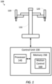
- FIG. 1 is a simplified diagram of a computer-assisted system 100 according to some embodiments.
- computer-assisted system 100 includes a device 110 with one or more movable or articulated arms 120.
- Each of the one or more articulated arms 120 may support one or more end effectors.
- device 110 may be consistent with a computer-assisted surgical device.
- the one or more articulated arms 120 each provide support for surgical instruments, imaging devices, and/or the like.
- Device 110 may further be coupled to an operator workstation (not shown), which may include one or more master controls for operating the device 110, the one or more articulated arms 120, and/or the end effectors.
- device 110 and the operator workstation may correspond to a da Vinci ® Surgical System commercialized by Intuitive Surgical, Inc. of Sunnyvale, California.
- computer-assisted surgical devices with other configurations, fewer or more articulated arms, and/or the like may be used with computer-assisted system 100.
- Control unit 130 includes a processor 140 coupled to memory 150. Operation of control unit 130 is controlled by processor 140. And although control unit 130 is shown with only one processor 140, it is understood that processor 140 may be representative of one or more central processing units, multi-core processors, microprocessors, microcontrollers, digital signal processors, field programmable gate arrays (FPGAs), application specific integrated circuits (ASICs), and/or the like in control unit 130. Control unit 130 may be implemented as a stand-alone subsystem and/or board added to a computing device or as a virtual machine. In some embodiments, control unit may be included as part of the operator workstation and/or operated separately from, but in coordination with the operator workstation.
- Memory 150 may be used to store software executed by control unit 130 and/or one or more data structures used during operation of control unit 130.
- Memory 150 may include one or more types of machine readable media. Some common forms of machine readable media may include floppy disk, flexible disk, hard disk, magnetic tape, any other magnetic medium, CD-ROM, any other optical medium, punch cards, paper tape, any other physical medium with patterns of holes, RAM, PROM, EPROM, FLASH-EPROM, any other memory chip or cartridge, and/or any other medium from which a processor or computer is adapted to read.
- memory 150 includes a motion control application 160 that may be used to support autonomous and/or semiautonomous control of device 110.
- Motion control application 160 may include one or more application programming interfaces (APIs) for receiving position, motion, and/or other sensor information from device 110, exchanging position, motion, and/or collision avoidance information with other control units regarding other devices, and/or planning and/or assisting in the planning of motion for device 110, articulated arms 120, and/or the end effectors of device 110.
- APIs application programming interfaces
- motion control application 160 is depicted as a software application, motion control application 160 may be implemented using hardware, software, and/or a combination of hardware and software.
- computer-assisted system 100 may be found in an operating room and/or an interventional suite. And although computer-assisted system 100 includes only one device 110 with two articulated arms 120, one of ordinary skill would understand that computer-assisted system 100 may include any number of devices with articulated arms and/or end effectors of similar and/or different design from device 110. In some examples, each of the devices may include fewer or more articulated arms and/or end effectors.
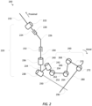
- FIG. 2 is a simplified diagram showing an articulated arm 200 according to some embodiments.
- the articulated arm 200 may be a portion of one of the articulated arms 120 in device 110.
- the articulated arm 200 includes various links and joints.
- At the most proximal end of the articulated arm 200 is coupled to a platform 210.
- platform 210 may be at a distal end of additional joints and links (not shown) from a computer-assisted device.
- Coupled to platform 210 is a series of set-up joints and links 220.
- the set-up joints and links 220 is rotationally coupled to platform 210 via a first set-up linkage joint 222.
- additional set-up links and joints for other articulated arms may be rotationally coupled to platform 210 using additional first set-up linkage joints.
- first set-up linkage joint 222 Coupled to the first set-up linkage joint 222 is a set-up base linkage 224 that is coupled to a proximal end of a set-up linkage extension link 226 via a first set-up linkage prismatic joint 228.
- a distal end of the set-up linkage extension link 226 is coupled to a proximal end of a set-up linkage vertical link 230 via a second set-up linkage prismatic joint 232.
- a distal end of the set-up linkage vertical link 230 is rotationally coupled to a proximal end of a support link 234 via a second set-up linkage joint 236.
- a first rotational joint 238 is coupled to a distal end of the support link 234.
- the first rotational joint 238 provides rotational control over the additional links and joints located distal to the first rotational joint 238.
- a central axis 250 of the first rotational joint 238 may be aligned with a remote center 290 that may be fixed in location during teleoperation of the articulated arm 200.
- a coupling link 240 couples the first rotational joint 238 to a second rotational joint 242.
- the second rotational joint 240 is coupled to a yaw joint 252 via a yaw link 254.
- Coupled distal to the yaw joint 252 is a parallelogram pitch mechanism 260.
- At a proximal end of the parallelogram pitch mechanism 260 is a first pitch link 262 coupling the yaw joint 252 to a first pitch joint 264.
- a second pitch link 266 couples the first pitch joint 264 to a second pitch joint 268.
- a third pitch link 270 couples the second pitch joint 268 to a third pitch joint 272.
- An instrument carriage is coupled to the third pitch joint 272 and includes an instrument shaft 280.
- One or more end effectors may be coupled to a distal end of the instrument shaft 280.
- the parallel pitch mechanism 260 may be controlled to maintain the instrument shaft 280 in alignment with the remote center 290.
- the articulated arm 200 includes numerous linkages 224, 226, 230, 234, 240, 254, 262, 266, 270, and 280 whose relative positions and/or orientations may be adjusted using numerous prismatic joints 228 and 232 as well as numerous rotational joints 222, 236, 238, 242, 262, 264, 268, and 272.
- Each of the prismatic and rotational joints may include one or more sensors for sensing position, rotation, movement, force, torque, and/or the like on the respective joints.
- each of the various joints may be non-actuated or actuated joints.
- a non-actuated joint may not include any actuators so that it is not capable of motion via teleoperation and/or motion control commands from a control unit for the articulated arm 200.
- the non-actuated joint may include a brake the permits the control unit to prevent and/or restrict motion in the non-actuated joint.
- joints 228, 232, and/or 236 may be non-actuated joints.
- an actuated joint may include one or more actuators that may control motion of the actuated joint via teleoperation and/or motion commands.
- an actuated joint may further include a brake.
- the various joints and links in the articulated arm 200 may be placed in a locked state where each of the non-actuated joint brakes are activated and each of the actuated joint actuators are commanded to hold the actuated joints at a commanded position.
- the locked state may additionally prevent unwanted motion due to gravity acting on the articulated arm 200.
- the articulated arm 200 may include one or more clutch buttons or controls.
- the clutch buttons may be located at various locations along the instrument carriage.
- additional clutch controls may be activated via operator controls at an operator console.
- one or more joints of the articulated arm may be switched from the locked state to a clutched or float state in which at least some of the non-actuated joint brakes may be at least partially released and at least some of the of the actuated joint actuators may permit motion of the joint away from the commanded positions.
- activation of a clutch button located on the articulated arm 200 may place the articulated arm 200 in the float state while other portions of the computer-assisted device coupled to the platform 210 remain in the locked state. While the joints of the articulated arm 200 are in the float state, an operator may manually position and/or orient the articulated arm 200 into a desired working position and orientation.
- manual activation of the clutching mechanisms of the articulated arm 200 may not always be practical and/or prudent.
- location of the clutch buttons or controls may not be convenient for easy activation by an operator.
- the operator may not have a free finger and/or hand to operate the clutch controls.
- coordination of the clutch controls with another operator located at an operator console may not be possible and/or practical.
- the operator may not be able to operate the clutch controls without breaking a sterile field established around portions of the articulated arm 200.
- movement of the articulated arm 200 may be desired without manual clutch activation.
- inadvertent collisions may occur between the operator, a patient, and/or an object and one or more links and/or joints of the articulated arm 200. In some examples, these inadvertent collisions may result in injury to the operator, injury to the patient, damage to the object, and/or damage to the articulated arm 200 due to the rigid position and/or orientation being maintained by the articulated arm 200. In some examples, being able to detect an inadvertent collision and have the articulated arm 200 automatically enter the float state may reduce injury to the operator, injury to the patient, damage to the object, and/or damage to the articulated arm 200.
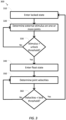
- Figure 3 is a simplified diagram of a method 300 of breakaway clutching according to some embodiments.
- One or more of the processes 310-360 of method 300 may be implemented, at least in part, in the form of executable code stored on non-transient, tangible, machine readable media that when run by one or more processors (e.g., the processor 140 in control unit 130) may cause the one or more processors to perform one or more of the processes 310-360.
- the method 300 may be performed by an application, such as motion control application 160.
- a locked state is entered. Joints of an articulated arm, such as articulated arms 120 and/or 200 may be placed in the locked state by default. In the locked state, motion of the articulated arm may be prevented and/or reduced by activating brakes in each of the non-actuated joints of the articulated arm and holding each of the actuated joints of the articulated arm at a respective commanded position using corresponding actuated joint actuators.
- external stimulus on one or more joints is determined.
- the one or more sensors associated with each of the joints of the articulated arm are periodically read and/or monitored to determine whether there is any external stimulus being applied to the one or more joints of the articulated arm.
- linear sensors associated with prismatic joints and/or rotation sensors associated with rotational joints are monitored to determine actual positions of respective joints.
- position errors may be determined based on differences between the actual positions and commanded positions in actuated joints and/or braked positions in non-actuated joints.
- the position errors may be converted to approximate forces and/or torques on the respective joints by using one or more kinematic models, inverse Jacobian transposes, and/or control models for the respective joints.
- the forces and/or torques on the respective joints may be measured using force and/or torque sensors, respectively, monitoring the respective joints.
- joint velocities of the actuated joints may also be determined using one or more velocity sensors associated with actuated joints or numerically based on changes in the actual positions of the actuated joints.
- joints of the articulated arm are be switched to the float state using a process 340 when any one of the external joint stimulus values exceeds a respective unlock threshold.
- joints of the articulated arm may be switched to the float state when a combination of two or more of the external joint stimulus values exceed respective unlock thresholds.
- joints of the articulated arm may be switched to the float state when a weighted and/or un-weighted aggregation of external stimulus values from two or more joints exceeds a composite unlock threshold.
- the aggregation may include an average, a median, a sum of squares, a minimum, a maximum, and/or like.
- Each of the unlock thresholds for the respective joints are different depending upon the location and/or purpose of the respective joints in the articulated arm.
- the unlock thresholds may be adjusted based on a current pose, position, and/or orientation of the articulated arm.
- the unlock threshold for a respective joint may be adjusted and/or disabled when the respective joint is beyond a soft stop near an end of possible motion for the respective joint.
- the float state may be activated by default when the respective joint is beyond a soft stop.
- determination of whether the external stimulus exceeds a threshold may be limited to a subset of the joints in the articulated arm.
- external stimulus on non-actuated joints may not be monitored during process 320 and may not have corresponding unlock thresholds.
- the unlock thresholds may be adjusted based on a size and/or a mass of the articulated arm. In some examples, the unlock thresholds may be large enough to avoid accidental switching to the float state due to gravitational forces and/or errors in the joint sensors.
- an unlock threshold may correspond to a threshold value associated with a position error between an actual position of a joint and a commanded and/or braked position of the joints.
- the threshold value may be between 0.02 and 5 millimeters for a prismatic joint.
- the threshold value may be between 0.03 and 0.5 degrees for a rotational joint.
- one or more unlock thresholds may correspond to a force and/or torque being applied to the joint, either as measured and/or as determined during process 320.
- the threshold value may be between 1 and 30 N for a force on a prismatic joint.
- the threshold value may be between 1 and 30 N-m for a torque on a rotational joint.
- the threshold value may exceed a force and/or torque saturation value for the joint.
- the unlock thresholds should be exceeded for a predetermined period of time before switching the articulated arm to the float state.
- joints of the articulated arm may be switched to the float state when a respective external stimulus value exceeds a corresponding unlock threshold continuously for the predetermined period of time.
- joints of the articulated arm may be switched to the float state when an aggregate, such as an average, of a respective external stimulus value over the predetermined period of time exceeds a respective stimulus value.
- a sliding window and/or exponential smoothing may be used to determine the aggregate.
- a filter may be used on the sensed external stimulus which puts an emphasis on mid-frequencies in order to better isolate disturbances due to human intention from disturbances due to gravity and other environmental factors which may be at low frequencies.
- the mid-frequencies may extend from approximately 0.01 Hz to 10 Hz.
- a discrete wavelet transform may be used in place of or combined with a filter to better isolate disturbances due to human intention.
- the predetermined period of time may be set by an operator. In some examples, the predetermined period of time may be between 50 and 150 milliseconds.
- the predetermined period of time may be different a first time breakaway clutching is activated, to avoid accidental switching to the float state due to residual momentum in the articulated arm due to other recently completed motion and/or static disturbances from the environment being confused with user input.
- the locked state should be established with the external stimulus below the unlock threshold for a predetermined period of time before the first time breakaway clutching is activated, to avoid accidental switching to the float state due to likely transient situations, such as when an articulated arm is undocked from a patient, an end effector is attached or removed from the articulated arm, and/or the like.
- the predetermined time may be extended between an additional 100 and 250 milliseconds after breakaway clutching is enabled.
- the external stimulus When the external stimulus does not exceed the one or more unlock thresholds, the external stimulus is determined again using process 320. When the external stimulus exceeds the one or more unlock thresholds, joints of the articulated arm are switched to the float state using process 340.
- the float state is entered.
- One or more of the joints of the articulated arm are placed in a float state where free and/or mostly free movement of the joints is permitted.
- the joints being placed in the float state may be a subset of the joints in the articulated arm. In some examples, this permits breakaway clutching to apply to those portions of the articulated arm subject to the external stimulus.
- the brakes on each of the non-actuated joints being placed in the float state may be released allowing motion of each of the non-actuated joints.
- each of the actuated joints being placed in the float state may be commanded to move to the actual positions determined during process 320 or while the actuated joints remain in the float state.
- each of the actuated joints being placed in the float state may also be commanded to match the joint velocities determined during process 320 or while the actuated joints remain in the float state.
- setting the command positions of a feedback controller of the actuated joints to the actual positions and/or the command velocities of the feedback controller to the actual joint velocities gives the impression that the actuated joints are moving freely, and when gravity compensation is also being applied, then also with the impression of apparent weightlessness.
- the movement of the joints in the float state may be subject to damping.
- one or more of the joints placed in the float state may be subject to some form of damped motion.
- the damped motion may be implemented on non-actuated joints by partially releasing the brakes so as to place a drag on movement of the non-actuated joints.
- the brakes may be partially released by controlling one or more voltage, currents, duty cycles, and/or the like of signals used to control the brakes.
- the damped motion may be implemented on actuated joints by commanding the actuated joints to move a portion of the distance behind the actual position based on direction of motion, by increasing a derivative constant in the feedback controller without significantly affecting its stability margins, and/or by introducing a backward current and/or voltage on the actuators of the actuated joints to emulate a resisting force and/or torque.
- the damped motion may be implemented on actuated joints by commanding the velocities of the actuated joints to a value below the joint velocities determined during process 320 or while the actuated joints remain in the float state.
- the damped motion may be adjusted to account for a current pose, position, and/or orientation of the articulated arm, a size and/or a mass of the articulated arm, and/or the like.
- one or more of the joints in the articulated arm that are not placed in the float state may be subject to compliant motion restrictions.
- the joints not placed in the float state may be commanded in response to detected movements of the joints placed in the float state.
- the joints not placed in the float state may be commanded to one or more positions and/or orientations.
- one or more of the joints in the parallelogram pitch mechanism 260 may be commanded to maintain intersection of the instrument shaft 280 with the central axis 250 at the remote center 290.
- joint velocities are determined.
- the one or more sensors associated with each of the joints of the articulated arm are periodically read and/or monitored to determine the velocities of each of the joints that are in the float state.
- changes in linear and/or rotational position between two consecutive monitoring intervals are used to estimate the joint velocities.
- numerical and/or other differentiation techniques may be used to determine the joint velocities from the sensed positions.
- velocity sensors on the joints may be monitored.
- a process 360 it is determined whether the joint velocities drop below a lock threshold.
- the joint velocities determined during process 350 are compared to one or more lock thresholds to see whether any continuing motion is detected in the articulated arm.
- each of the joint velocities may be compared to a corresponding lock threshold. When each of the joint velocities is below its corresponding lock threshold, lack of motion is detected and the joints of the articulated arm are switched to the locked state using process 310.
- joints of the articulated arm may be switched to the locked state using process 310 when a weighted and/or un-weighted aggregation of joint velocities from each of the joints is below a composite lock threshold.
- the aggregation may include an average, a median, a sum of squares, a minimum, a maximum, and/or like.
- Each of the lock thresholds for respective joints is different depending upon the location and/or purpose of the respective joints in the articulated arm.
- the lock thresholds may be adjusted based on a current, pose position, and/or orientation of the articulated arm.
- the lock threshold for a respective joint may be adjusted and/or disabled when the respective joint is beyond a soft stop near an end of possible motion for the respective joint.
- the locked state may be activated by default when the respective joint is beyond a soft stop.
- determination of whether the joint velocities are below the lock thresholds may be limited to a subset of the joints in the articulated arm.
- the lock thresholds may be adjusted based on a size and/or a mass of the articulated arm. In some examples, the lock thresholds may be large enough to avoid accidental switching to the lock due to errors in the joint sensors.
- the lock threshold may be between 0.1 and 10 millimeters per second for a prismatic joint. In some examples, the threshold value may be between 0.25 and 10 degrees per second for a rotational joint.
- the joint velocities should remain below the lock thresholds for a predetermined period of time before switching the joints of the articulated arm to the locked state.
- joints of the articulated arm may be switched to the locked state when the joint velocities are below a corresponding lock threshold continuously for the predetermined period of time.
- joints of the articulated arm may be switch to the locked state when an aggregate, such as an average, of a respective joint velocity over the predetermined period of time is below a respective lock threshold.
- a sliding window and/or exponential smoothing may be used to determine the aggregate.
- the predetermined period of time may be set by an operator. In some examples, the predetermined period of time may be between 100 and 200 milliseconds.
- the joint velocities are determined again using process 350.
- the joints of the articulated arm are switched to the locked state using process 310.
- the breakaway clutching of method 300 may be disabled during certain operating modes of the articulated arm.
- breakaway clutching may be disabled when the articulated arm is in a hard locked state during storage and/or when a cart on which the articulated arm is mounted is being transported between locations.
- breakaway clutching may be disabled when the articulated arm is in an actuated teleoperation mode and/or executing commanded motion, such as when docked to a patient.
- disabling breakaway clutching during actuated operation may reduce the likelihood that manual interference and/or collision with the articulated arm will interfere with the teleoperation and/or commanded motion and thus reduce the further likelihood of damaging objects being manipulated and/or causing injury to a patient on which the articulated arm is being used.
- breakaway clutching may be adjusted, forced, or disabled when any of the joints in the articulated arm is beyond a soft stop position.
- control units such as control unit 130 may include non-transient, tangible, machine readable media that include executable code that when run by one or more processors (e.g., processor 140) may cause the one or more processors to perform the processes of method 300.
- processors e.g., processor 140
- Some common forms of machine readable media that may include the processes of method 300 are, for example, floppy disk, flexible disk, hard disk, magnetic tape, any other magnetic medium, CD-ROM, any other optical medium, punch cards, paper tape, any other physical medium with patterns of holes, RAM, PROM, EPROM, FLASH-EPROM, any other memory chip or cartridge, and/or any other medium from which a processor or computer is adapted to read.
Claims (15)
- Computerassistierte medizinische Vorrichtung (100), die Folgendes umfasst:einen Gelenkarm (120) mit einem ersten Gelenk; undeine Steuereinheit (130), die mit dem Gelenkarm (120) gekoppelt ist und einen oder mehrere Prozessoren (140) umfasst;wobei die Steuereinheit (130) konfiguriert ist zum:Umschalten des ersten Gelenks (222, 228, 232, 236, 238, 242, 262, 264, 268, 272) von einem verriegelten Zustand des ersten Gelenks (222, 228, 232, 236, 238, 242, 262, 264, 268, 272) in einen Schwebezustand des ersten Gelenks (222, 228, 232, 236, 238, 242, 262, 264, 268, 272), wenn ein Reiz, der mit dem ersten Gelenk (222, 228, 232, 236, 238, 242, 262, 264, 268, 272) assoziiert ist, eine erste Entriegelungsschwelle übersteigt, wobei die Bewegung des ersten Gelenks (222, 228, 232, 236, 238, 242, 262, 264, 268, 272) im verriegelten Zustand des ersten Gelenks (222, 228, 232, 236, 238, 242, 262, 264, 268, 272) eingeschränkt ist und die Bewegung im Schwebezustand des ersten Gelenks (222, 228, 232, 236, 238, 242, 262, 264, 268, 272)zugelassen wird; undUmschalten des ersten Gelenks (222, 228, 232, 236, 238, 242, 262, 264, 268, 272) vom Schwebezustand in den verriegelten Zustand, wenn eine Geschwindigkeit, die mit dem ersten Gelenk (222, 228, 232, 236, 238, 242, 262, 264, 268, 272) assoziiert ist, unter eine erste Verriegelungsschwelle fällt;dadurch gekennzeichnet, dassdie erste Entriegelungsschwelle auf einer Stelle des ersten Gelenks (222, 228, 232, 236, 238, 242, 262, 264, 268, 272) in dem Gelenkarm basiert oderdie erste Verriegelungsschwelle auf der Stelle des ersten Gelenks (222, 228, 232, 236, 238, 242, 262, 264, 268, 272) in dem Gelenkarm basiert.
- Computerassistierte medizinische Vorrichtung nach Anspruch 1, wobei:die erste Entriegelungsschwelle auf der Basis einer Lage, einer Position oder einer Orientierung des Gelenkarms justiert wird oderdie erste Verriegelungsschwelle auf der Basis der Lage, der Position oder der Orientierung des Gelenkarms justiert wird.
- Vorrichtung (100) nach Anspruch 1 oder 2, wobei die Steuereinheit (130) konfiguriert ist zum:Umschalten des ersten Gelenks (222, 228, 232, 236, 238, 242, 262, 264, 268, 272) vom verriegelten Zustand in den Schwebezustand, wenn ein Gesamtreiz auf dem ersten Gelenk (222, 228, 232, 236, 238, 242, 262, 264, 268, 272) über eine vorbestimmte Zeitperiode einen Reizwert übersteigt; oderUmschalten des ersten Gelenks (222, 228, 232, 236, 238, 242, 262, 264, 268, 272) vom verriegelten Zustand in den Schwebezustand, wenn der Reiz auf dem ersten Gelenk (222, 228, 232, 236, 238, 242, 262, 264, 268, 272) die erste Entriegelungsschwelle kontinuierlich eine vorbestimmte Zeitperiode übersteigt; oderHalten des ersten Gelenks (222, 228, 232, 236, 238, 242, 262, 264, 268, 272) im verriegelten Zustand für eine vorbestimmte Zeitperiode vor dem erstmaligen Umschalten des ersten Gelenks (222, 228, 232, 236, 238, 242, 262, 264, 268, 272) in den Schwebezustand.
- Vorrichtung (100) nach einem der Ansprüche 1 bis 3, wobei die Steuereinheit (130) konfiguriert ist zum:Umschalten des ersten Gelenks (222, 228, 232, 236, 238, 242, 262, 264, 268, 272) vom verriegelten Zustand in den Schwebezustand, wenn ein Reiz, der mit dem zweiten Gelenk (222, 228, 232, 236, 238, 242, 262, 264, 268, 272) des Gelenkarms (120) assoziiert ist, eine zweite Entriegelungsschwelle übersteigt; oderUmschalten des ersten Gelenks (222, 228, 232, 236, 238, 242, 262, 264, 268, 272) vom verriegelten Zustand in den Schwebezustand, wenn ein Gesamtwert des Reizes, der mit dem ersten Gelenk (222, 228, 232, 236, 238, 242, 262, 264, 268, 272) assoziiert ist, und des Reizes, der mit dem zweiten Gelenk (222, 228, 232, 236, 238, 242, 262, 264, 268, 272) assoziiert ist, eine zusammengesetzte Entriegelungsschwelle übersteigt.
- Vorrichtung (100) nach einem der Ansprüche 1 bis 4, wobei die Steuereinheit (130) konfiguriert ist zum:Umschalten des ersten Gelenks (222, 228, 232, 236, 238, 242, 262, 264, 268, 272) vom Schwebezustand in den verriegelten Zustand, wenn ein Gesamtwert der Geschwindigkeit, die mit dem ersten Gelenk (222, 228, 232, 236, 238, 242, 262, 264, 268, 272) assoziiert ist, über eine vorbestimmte Zeitperiode unter die erste Verriegelungsschwelle fällt; oderUmschalten des ersten Gelenks (222, 228, 232, 236, 238, 242, 262, 264, 268, 272) vom Schwebezustand in den verriegelten Zustand, wenn die Geschwindigkeit, die mit dem ersten Gelenk (222, 228, 232, 236, 238, 242, 262, 264, 268, 272) assoziiert ist, kontinuierlich für die vorbestimmte Zeitperiode unter der ersten Verriegelungsschwelle liegt.
- Vorrichtung (100) nach einem der Ansprüche 1 bis 5, wobei der Reiz Folgendem entspricht:einem Positionsfehler zwischen einer befohlenen Position des ersten Gelenks (222, 228, 232, 236, 238, 242, 262, 264, 268, 272) und einer Ist-Position des ersten Gelenks (222, 228, 232, 236, 238, 242, 262, 264, 268, 272), wobei das erste Gelenk (222, 228, 232, 236, 238, 242, 262, 264, 268, 272) ein betätigtes Gelenk (222, 238, 242, 262, 264, 268, 272) ist; odereinem Positionsfehler des ersten Gelenks (222, 228, 232, 236, 238, 242, 262, 264, 268, 272) zwischen einer gebremsten Position des ersten Gelenks (222, 228, 232, 236, 238, 242, 262, 264, 268, 272) und einer Ist-Position des ersten Gelenks (222, 228, 232, 236, 238, 242, 262, 264, 268, 272), wobei das erste Gelenk (222, 228, 232, 236, 238, 242, 262, 264, 268, 272) ein nicht betätigtes Gelenk (228, 232, 236) ist; odereiner Kraft oder einem Drehmoment auf dem ersten Gelenk (222, 228, 232, 236, 238, 242, 262, 264, 268, 272).
- Vorrichtung (100) nach einem der Ansprüche 1 bis 6, wobeidie erste Entriegelungsschwelle darauf basiert, ob das erste Gelenk (222, 228, 232, 236, 238, 242, 262, 264, 268, 272) jenseits einer Soft-Stop-Position ist; oderdie erste Verriegelungsschwelle darauf basiert, ob das erste Gelenk (222, 228, 232, 236, 238, 242, 262, 264, 268, 272) jenseits der Soft-Stop-Position ist; oderdie Steuereinheit dazu konfiguriert ist, das erste Gelenk (222, 228, 232, 236, 238, 242, 262, 264, 268, 272) vom verriegelten Zustand in den Schwebezustand umzuschalten, wenn das erste Gelenk (222, 228, 232, 236, 238, 242, 262, 264, 268, 272) jenseits der Soft-Stop-Position ist.
- Vorrichtung (100) nach einem der Ansprüche 1 bis 7, wobei das erste Gelenk (222, 228, 232, 236, 238, 242, 262, 264, 268, 272) ein nicht betätigtes Gelenk (228, 232, 236) ist und wobei:die Steuereinheit (130) dazu konfiguriert ist, eine Bremse an dem ersten Gelenk (222, 228, 232, 236, 238, 242, 262, 264, 268, 272) im verriegelten Zustand zu aktivieren, oderdie Steuereinheit (130) dazu konfiguriert ist, die Bremse an dem ersten Gelenk (222, 228, 232, 236, 238, 242, 262, 264, 268, 272) im Schwebezustand wenigstens teilweise zu lösen.
- Vorrichtung (100) nach einem der Ansprüche 1 bis 8, wobei das erste Gelenk (222, 228, 232, 236, 238, 242, 262, 264, 268, 272) ein betätigtes Gelenk ist und wobeidie Steuereinheit (130) dazu konfiguriert ist, das erste Gelenk (222, 228, 232, 236, 238, 242, 262, 264, 268, 272) in einer befohlenen Position im verriegelten Zustand zu halten, oderdie Steuereinheit (130) dazu konfiguriert ist, das erste Gelenk (222, 228, 232, 236, 238, 242, 262, 264, 268, 272) in eine Ist-Position des ersten Gelenks im Schwebezustand zu befehlen, oderdie Steuereinheit (130) dazu konfiguriert ist, das erste Gelenk (222, 228, 232, 236, 238, 242, 262, 264, 268, 272) in eine Ist-Geschwindigkeit des ersten Gelenks im Schwebezustand zu befehlen.
- Vorrichtung (100) nach einem der Ansprüche 1 bis 9, wobei die Steuereinheit (130) dazu konfiguriert ist, ein Umschalten des ersten Gelenks (222, 228, 232, 236, 238, 242, 262, 264, 268, 272) in den Schwebezustand zu verhindern, wenn der Gelenkarm (120) in einem vorbestimmten Betriebsmodus ist, wobei der vorbestimmte Betriebsmodus einen Modus umfasst, der ausgewählt ist aus der Gruppe bestehend aus: einem Transportmodus, einem Teleoperationsmodus, einem befohlenen Bewegungsmodus und einem an einem Patienten angedockten Modus.
- Verfahren zum Bewegen einer medizinischen Vorrichtung (100) in eine gewünschte Arbeitsposition und - orientierung vor dem Benutzen der medizinischen Vorrichtung (100), wobei das Verfahren Folgendes umfasst:Umschalten eines ersten Gelenks (222, 228, 232, 236, 238, 242, 262, 264, 268, 272) eines Gelenkarms (120) der medizinischen Vorrichtung (100) von einem verriegelten Zustand des ersten Gelenks (222, 228, 232, 236, 238, 242, 262, 264, 268, 272) in einen Schwebezustand des ersten Gelenks (222, 228, 232, 236, 238, 242, 262, 264, 268, 272), wenn ein Reiz, der mit dem ersten Gelenk (222, 228, 232, 236, 238, 242, 262, 264, 268, 272) assoziiert ist, eine erste Entriegelungsschwelle übersteigt, wobei die Bewegung des ersten Gelenks (222, 228, 232, 236, 238, 242, 262, 264, 268, 272) im verriegelten Zustand des ersten Gelenks (222, 228, 232, 236, 238, 242, 262, 264, 268, 272) eingeschränkt ist und die Bewegung im Schwebezustand des ersten Gelenks (222, 228, 232, 236, 238, 242, 262, 264, 268, 272)zugelassen wird; undUmschalten des ersten Gelenks (222, 228, 232, 236, 238, 242, 262, 264, 268, 272) vom Schwebezustand in den verriegelten Zustand, wenn eine Geschwindigkeit, die mit dem ersten Gelenk (222, 228, 232, 236, 238, 242, 262, 264, 268, 272) assoziiert ist, unter eine erste Verriegelungsschwelle fällt;dadurch gekennzeichnet, dassdie erste Entriegelungsschwelle auf einer Stelle des ersten Gelenks (222, 228, 232, 236, 238, 242, 262, 264, 268, 272) in dem Gelenkarm basiert oderdie erste Verriegelungsschwelle auf der Stelle des ersten Gelenks (222, 228, 232, 236, 238, 242, 262, 264, 268, 272) in dem Gelenkarm basiert.
- Verfahren nach Anspruch 11, wobei:die erste Entriegelungsschwelle auf der Basis einer Lage, einer Position oder einer Orientierung des Gelenkarms justiert wird oderdie erste Verriegelungsschwelle auf der Basis der Lage, der Position oder der Orientierung des Gelenkarms justiert wird.
- Verfahren nach Anspruch 11 oder 12, weiterhin umfassend:Umschalten des ersten Gelenks (222, 228, 232, 236, 238, 242, 262, 264, 268, 272) vom verriegelten Zustand in den Schwebezustand, wenn ein Gesamtreiz auf dem ersten Gelenk (222, 228, 232, 236, 238, 242, 262, 264, 268, 272) über eine vorbestimmte Zeitperiode einen Reizwert übersteigt; oderUmschalten des ersten Gelenks (222, 228, 232, 236, 238, 242, 262, 264, 268, 272) vom verriegelten Zustand in den Schwebezustand, wenn der Reiz auf dem ersten Gelenk (222, 228, 232, 236, 238, 242, 262, 264, 268, 272) die erste Entriegelungsschwelle kontinuierlich eine vorbestimmte Zeitperiode übersteigt; oderUmschalten des ersten Gelenks (222, 228, 232, 236, 238, 242, 262, 264, 268, 272) vom verriegelten Zustand in den Schwebezustand, wenn ein Reiz, der mit dem zweiten Gelenk (222, 228, 232, 236, 238, 242, 262, 264, 268, 272) des Gelenkarms (120) assoziiert ist, eine zweite Entriegelungsschwelle übersteigt; oderUmschalten des ersten Gelenks (222, 228, 232, 236, 238, 242, 262, 264, 268, 272) vom verriegelten Zustand in den Schwebezustand, wenn ein Gesamtwert des Reizes, der mit dem ersten Gelenk (222, 228, 232, 236, 238, 242, 262, 264, 268, 272) assoziiert ist, und des Reizes, der mit dem zweiten Gelenk (222, 228, 232, 236, 238, 242, 262, 264, 268, 272) assoziiert ist, eine zusammengesetzte Entriegelungsschwelle übersteigt;Halten des ersten Gelenks (222, 228, 232, 236, 238, 242, 262, 264, 268, 272) im verriegelten Zustand für eine vorbestimmte Zeitperiode vor dem erstmaligen Umschalten des ersten Gelenks (222, 228, 232, 236, 238, 242, 262, 264, 268, 272) in den Schwebezustand.
- Verfahren nach einem der Ansprüche 11 bis 13, weiterhin umfassend:Umschalten des ersten Gelenks (222, 228, 232, 236, 238, 242, 262, 264, 268, 272) vom Schwebezustand in den verriegelten Zustand, wenn ein Gesamtwert der Geschwindigkeit, die mit dem ersten Gelenk (222, 228, 232, 236, 238, 242, 262, 264, 268, 272) assoziiert ist, über eine vorbestimmte Zeitperiode unter die erste Verriegelungsschwelle fällt; oderUmschalten des ersten Gelenks (222, 228, 232, 236, 238, 242, 262, 264, 268, 272) vom Schwebezustand in den verriegelten Zustand, wenn die Geschwindigkeit, die mit dem ersten Gelenk (222, 228, 232, 236, 238, 242, 262, 264, 268, 272) assoziiert ist, kontinuierlich für die vorbestimmte Zeitperiode unter der ersten Verriegelungsschwelle liegt.
- Nichtflüchtiges maschinenlesbares Medium (150), das mehrere maschinenlesbare Anweisungen umfasst, die bei Ausführung durch einen oder mehrere Prozessoren (140), die mit einer medizinischen Vorrichtung nach einem der Ansprüche 1-10 assoziiert sind, ausgelegt sind zum Bewirken, dass der eine oder die mehreren Prozessoren (140) das Verfahren nach einem der Ansprüche 11-14 durchführen.
Priority Applications (1)
| Application Number | Priority Date | Filing Date | Title |
|---|---|---|---|
| EP23191917.6A EP4248901A3 (de) | 2014-03-17 | 2015-03-17 | System und verfahren zur losbrechkupplung in einem gelenkarm |
Applications Claiming Priority (3)
| Application Number | Priority Date | Filing Date | Title |
|---|---|---|---|
| US201461954120P | 2014-03-17 | 2014-03-17 | |
| EP15764121.8A EP3119314B1 (de) | 2014-03-17 | 2015-03-17 | System und verfahren zur lösbaren kupplung in einem gelenkarm |
| PCT/US2015/021074 WO2015142930A1 (en) | 2014-03-17 | 2015-03-17 | System and method for breakaway clutching in an articulated arm |
Related Parent Applications (2)
| Application Number | Title | Priority Date | Filing Date |
|---|---|---|---|
| EP15764121.8A Division-Into EP3119314B1 (de) | 2014-03-17 | 2015-03-17 | System und verfahren zur lösbaren kupplung in einem gelenkarm |
| EP15764121.8A Division EP3119314B1 (de) | 2014-03-17 | 2015-03-17 | System und verfahren zur lösbaren kupplung in einem gelenkarm |
Related Child Applications (2)
| Application Number | Title | Priority Date | Filing Date |
|---|---|---|---|
| EP23191917.6A Division EP4248901A3 (de) | 2014-03-17 | 2015-03-17 | System und verfahren zur losbrechkupplung in einem gelenkarm |
| EP23191917.6A Division-Into EP4248901A3 (de) | 2014-03-17 | 2015-03-17 | System und verfahren zur losbrechkupplung in einem gelenkarm |
Publications (2)
| Publication Number | Publication Date |
|---|---|
| EP3682837A1 EP3682837A1 (de) | 2020-07-22 |
| EP3682837B1 true EP3682837B1 (de) | 2023-09-27 |
Family
ID=54145236
Family Applications (3)
| Application Number | Title | Priority Date | Filing Date |
|---|---|---|---|
| EP23191917.6A Pending EP4248901A3 (de) | 2014-03-17 | 2015-03-17 | System und verfahren zur losbrechkupplung in einem gelenkarm |
| EP20161333.8A Active EP3682837B1 (de) | 2014-03-17 | 2015-03-17 | System und verfahren zur lösbaren kupplung in einem gelenkarm |
| EP15764121.8A Active EP3119314B1 (de) | 2014-03-17 | 2015-03-17 | System und verfahren zur lösbaren kupplung in einem gelenkarm |
Family Applications Before (1)
| Application Number | Title | Priority Date | Filing Date |
|---|---|---|---|
| EP23191917.6A Pending EP4248901A3 (de) | 2014-03-17 | 2015-03-17 | System und verfahren zur losbrechkupplung in einem gelenkarm |
Family Applications After (1)
| Application Number | Title | Priority Date | Filing Date |
|---|---|---|---|
| EP15764121.8A Active EP3119314B1 (de) | 2014-03-17 | 2015-03-17 | System und verfahren zur lösbaren kupplung in einem gelenkarm |
Country Status (6)
| Country | Link |
|---|---|
| US (5) | US10034717B2 (de) |
| EP (3) | EP4248901A3 (de) |
| JP (3) | JP7150413B2 (de) |
| KR (3) | KR102457538B1 (de) |
| CN (2) | CN106255472B (de) |
| WO (1) | WO2015142930A1 (de) |
Families Citing this family (128)
| Publication number | Priority date | Publication date | Assignee | Title |
|---|---|---|---|---|
| US10893912B2 (en) | 2006-02-16 | 2021-01-19 | Globus Medical Inc. | Surgical tool systems and methods |
| US10653497B2 (en) | 2006-02-16 | 2020-05-19 | Globus Medical, Inc. | Surgical tool systems and methods |
| US10357184B2 (en) | 2012-06-21 | 2019-07-23 | Globus Medical, Inc. | Surgical tool systems and method |
| US9308050B2 (en) | 2011-04-01 | 2016-04-12 | Ecole Polytechnique Federale De Lausanne (Epfl) | Robotic system and method for spinal and other surgeries |
| US11857266B2 (en) | 2012-06-21 | 2024-01-02 | Globus Medical, Inc. | System for a surveillance marker in robotic-assisted surgery |
| US11399900B2 (en) | 2012-06-21 | 2022-08-02 | Globus Medical, Inc. | Robotic systems providing co-registration using natural fiducials and related methods |
| US11864839B2 (en) | 2012-06-21 | 2024-01-09 | Globus Medical Inc. | Methods of adjusting a virtual implant and related surgical navigation systems |
| US11253327B2 (en) | 2012-06-21 | 2022-02-22 | Globus Medical, Inc. | Systems and methods for automatically changing an end-effector on a surgical robot |
| US11793570B2 (en) | 2012-06-21 | 2023-10-24 | Globus Medical Inc. | Surgical robotic automation with tracking markers |
| US10624710B2 (en) | 2012-06-21 | 2020-04-21 | Globus Medical, Inc. | System and method for measuring depth of instrumentation |
| US10874466B2 (en) | 2012-06-21 | 2020-12-29 | Globus Medical, Inc. | System and method for surgical tool insertion using multiaxis force and moment feedback |
| US10136954B2 (en) | 2012-06-21 | 2018-11-27 | Globus Medical, Inc. | Surgical tool systems and method |
| US10231791B2 (en) | 2012-06-21 | 2019-03-19 | Globus Medical, Inc. | Infrared signal based position recognition system for use with a robot-assisted surgery |
| US11589771B2 (en) | 2012-06-21 | 2023-02-28 | Globus Medical Inc. | Method for recording probe movement and determining an extent of matter removed |
| US10758315B2 (en) | 2012-06-21 | 2020-09-01 | Globus Medical Inc. | Method and system for improving 2D-3D registration convergence |
| US11298196B2 (en) | 2012-06-21 | 2022-04-12 | Globus Medical Inc. | Surgical robotic automation with tracking markers and controlled tool advancement |
| US10350013B2 (en) | 2012-06-21 | 2019-07-16 | Globus Medical, Inc. | Surgical tool systems and methods |
| US11864745B2 (en) | 2012-06-21 | 2024-01-09 | Globus Medical, Inc. | Surgical robotic system with retractor |
| US10799298B2 (en) | 2012-06-21 | 2020-10-13 | Globus Medical Inc. | Robotic fluoroscopic navigation |
| US11045267B2 (en) | 2012-06-21 | 2021-06-29 | Globus Medical, Inc. | Surgical robotic automation with tracking markers |
| US11786324B2 (en) | 2012-06-21 | 2023-10-17 | Globus Medical, Inc. | Surgical robotic automation with tracking markers |
| US11896446B2 (en) | 2012-06-21 | 2024-02-13 | Globus Medical, Inc | Surgical robotic automation with tracking markers |
| US10646280B2 (en) | 2012-06-21 | 2020-05-12 | Globus Medical, Inc. | System and method for surgical tool insertion using multiaxis force and moment feedback |
| US11857149B2 (en) | 2012-06-21 | 2024-01-02 | Globus Medical, Inc. | Surgical robotic systems with target trajectory deviation monitoring and related methods |
| US11963755B2 (en) | 2012-06-21 | 2024-04-23 | Globus Medical Inc. | Apparatus for recording probe movement |
| US11607149B2 (en) | 2012-06-21 | 2023-03-21 | Globus Medical Inc. | Surgical tool systems and method |
| US11116576B2 (en) | 2012-06-21 | 2021-09-14 | Globus Medical Inc. | Dynamic reference arrays and methods of use |
| US11395706B2 (en) | 2012-06-21 | 2022-07-26 | Globus Medical Inc. | Surgical robot platform |
| US11317971B2 (en) | 2012-06-21 | 2022-05-03 | Globus Medical, Inc. | Systems and methods related to robotic guidance in surgery |
| US10842461B2 (en) | 2012-06-21 | 2020-11-24 | Globus Medical, Inc. | Systems and methods of checking registrations for surgical systems |
| JP2015528713A (ja) | 2012-06-21 | 2015-10-01 | グローバス メディカル インコーポレイティッド | 手術ロボットプラットフォーム |
| US9283048B2 (en) | 2013-10-04 | 2016-03-15 | KB Medical SA | Apparatus and systems for precise guidance of surgical tools |
| US9241771B2 (en) | 2014-01-15 | 2016-01-26 | KB Medical SA | Notched apparatus for guidance of an insertable instrument along an axis during spinal surgery |
| WO2015121311A1 (en) | 2014-02-11 | 2015-08-20 | KB Medical SA | Sterile handle for controlling a robotic surgical system from a sterile field |
| EP4248901A3 (de) | 2014-03-17 | 2023-11-29 | Intuitive Surgical Operations, Inc. | System und verfahren zur losbrechkupplung in einem gelenkarm |
| CN106659537B (zh) | 2014-04-24 | 2019-06-11 | Kb医疗公司 | 结合机器人手术系统使用的手术器械固持器 |
| WO2015193479A1 (en) | 2014-06-19 | 2015-12-23 | KB Medical SA | Systems and methods for performing minimally invasive surgery |
| EP3169252A1 (de) | 2014-07-14 | 2017-05-24 | KB Medical SA | Rutschfestes chirurgisches instrument zur verwendung bei der herstellung von löchern in knochengewebe |
| US10765438B2 (en) | 2014-07-14 | 2020-09-08 | KB Medical SA | Anti-skid surgical instrument for use in preparing holes in bone tissue |
| KR102617042B1 (ko) | 2014-10-27 | 2023-12-27 | 인튜어티브 서지컬 오퍼레이션즈 인코포레이티드 | 수술 테이블에 등록하기 위한 시스템 및 방법 |
| KR20230129615A (ko) | 2014-10-27 | 2023-09-08 | 인튜어티브 서지컬 오퍼레이션즈 인코포레이티드 | 기기 교란 보상을 위한 시스템 및 방법 |
| KR20230096131A (ko) | 2014-10-27 | 2023-06-29 | 인튜어티브 서지컬 오퍼레이션즈 인코포레이티드 | 통합 수술 테이블을 위한 시스템 및 방법 |
| WO2016069661A1 (en) | 2014-10-27 | 2016-05-06 | Intuitive Surgical Operations, Inc. | Medical device with active brake release control |
| EP3212151B1 (de) | 2014-10-27 | 2020-07-29 | Intuitive Surgical Operations, Inc. | System zur bewegung eines integrierten operationstisches |
| JP6774404B2 (ja) | 2014-10-27 | 2020-10-21 | インテュイティブ サージカル オペレーションズ, インコーポレイテッド | 統合手術台アイコンのためのシステム及び方法 |
| KR20240013853A (ko) | 2014-10-27 | 2024-01-30 | 인튜어티브 서지컬 오퍼레이션즈 인코포레이티드 | 반응 운동 동안 제어점을 감시하기 위한 시스템 및 방법 |
| JP6731920B2 (ja) | 2014-12-02 | 2020-07-29 | カーベー メディカル エスアー | 外科手術中のロボット支援式体積除去 |
| US10013808B2 (en) | 2015-02-03 | 2018-07-03 | Globus Medical, Inc. | Surgeon head-mounted display apparatuses |
| EP3258872B1 (de) | 2015-02-18 | 2023-04-26 | KB Medical SA | Syteme zur durchführung minimalinvasiver spinal-chirurgie mittles eines robotischen-chirurgischen system unter benutzung einer perkutanen technik |
| US10806530B2 (en) * | 2015-06-10 | 2020-10-20 | Intuitive Surgical Operations, Inc. | System and method for patient-side instrument control |
| US10058394B2 (en) | 2015-07-31 | 2018-08-28 | Globus Medical, Inc. | Robot arm and methods of use |
| US10646298B2 (en) | 2015-07-31 | 2020-05-12 | Globus Medical, Inc. | Robot arm and methods of use |
| US10080615B2 (en) | 2015-08-12 | 2018-09-25 | Globus Medical, Inc. | Devices and methods for temporary mounting of parts to bone |
| JP6894431B2 (ja) | 2015-08-31 | 2021-06-30 | ケービー メディカル エスアー | ロボット外科用システム及び方法 |
| US10034716B2 (en) | 2015-09-14 | 2018-07-31 | Globus Medical, Inc. | Surgical robotic systems and methods thereof |
| US9771092B2 (en) | 2015-10-13 | 2017-09-26 | Globus Medical, Inc. | Stabilizer wheel assembly and methods of use |
| US10842453B2 (en) | 2016-02-03 | 2020-11-24 | Globus Medical, Inc. | Portable medical imaging system |
| US10448910B2 (en) | 2016-02-03 | 2019-10-22 | Globus Medical, Inc. | Portable medical imaging system |
| US11883217B2 (en) | 2016-02-03 | 2024-01-30 | Globus Medical, Inc. | Portable medical imaging system and method |
| US10117632B2 (en) | 2016-02-03 | 2018-11-06 | Globus Medical, Inc. | Portable medical imaging system with beam scanning collimator |
| US11058378B2 (en) | 2016-02-03 | 2021-07-13 | Globus Medical, Inc. | Portable medical imaging system |
| JP6549496B2 (ja) * | 2016-02-18 | 2019-07-24 | 東朋テクノロジー株式会社 | 身体支持追従装置 |
| WO2017146890A1 (en) | 2016-02-26 | 2017-08-31 | Intuitive Surgical Operations, Inc. | System and method for collision avoidance using virtual boundaries |
| US10866119B2 (en) | 2016-03-14 | 2020-12-15 | Globus Medical, Inc. | Metal detector for detecting insertion of a surgical device into a hollow tube |
| US11039893B2 (en) | 2016-10-21 | 2021-06-22 | Globus Medical, Inc. | Robotic surgical systems |
| EP3351202B1 (de) | 2017-01-18 | 2021-09-08 | KB Medical SA | Universelle instrumentenführung für chirurgische robotersysteme |
| JP7233841B2 (ja) | 2017-01-18 | 2023-03-07 | ケービー メディカル エスアー | ロボット外科手術システムのロボットナビゲーション |
| JP2018114280A (ja) | 2017-01-18 | 2018-07-26 | ケービー メディカル エスアー | ロボット外科用システムのための汎用器具ガイド、外科用器具システム、及びそれらの使用方法 |
| US11071594B2 (en) | 2017-03-16 | 2021-07-27 | KB Medical SA | Robotic navigation of robotic surgical systems |
| US10675094B2 (en) | 2017-07-21 | 2020-06-09 | Globus Medical Inc. | Robot surgical platform |
| CN111093467A (zh) | 2017-07-27 | 2020-05-01 | 直观外科手术操作公司 | 医疗设备中的灯光显示器 |
| US11382666B2 (en) | 2017-11-09 | 2022-07-12 | Globus Medical Inc. | Methods providing bend plans for surgical rods and related controllers and computer program products |
| EP3492032B1 (de) | 2017-11-09 | 2023-01-04 | Globus Medical, Inc. | Chirurgische robotische systeme zum biegen von chirurgischen stäben |
| US11794338B2 (en) | 2017-11-09 | 2023-10-24 | Globus Medical Inc. | Robotic rod benders and related mechanical and motor housings |
| US11134862B2 (en) | 2017-11-10 | 2021-10-05 | Globus Medical, Inc. | Methods of selecting surgical implants and related devices |
| US20190254753A1 (en) | 2018-02-19 | 2019-08-22 | Globus Medical, Inc. | Augmented reality navigation systems for use with robotic surgical systems and methods of their use |
| US10573023B2 (en) | 2018-04-09 | 2020-02-25 | Globus Medical, Inc. | Predictive visualization of medical imaging scanner component movement |
| US11337742B2 (en) | 2018-11-05 | 2022-05-24 | Globus Medical Inc | Compliant orthopedic driver |
| US11278360B2 (en) | 2018-11-16 | 2022-03-22 | Globus Medical, Inc. | End-effectors for surgical robotic systems having sealed optical components |
| JP2022510027A (ja) | 2018-12-04 | 2022-01-25 | マコ サージカル コーポレーション | 外科用構成要素の結合に使用する滅菌バリア組立体を備えた実装システム |
| US11744655B2 (en) | 2018-12-04 | 2023-09-05 | Globus Medical, Inc. | Drill guide fixtures, cranial insertion fixtures, and related methods and robotic systems |
| US11602402B2 (en) | 2018-12-04 | 2023-03-14 | Globus Medical, Inc. | Drill guide fixtures, cranial insertion fixtures, and related methods and robotic systems |
| US11918313B2 (en) | 2019-03-15 | 2024-03-05 | Globus Medical Inc. | Active end effectors for surgical robots |
| US11382549B2 (en) | 2019-03-22 | 2022-07-12 | Globus Medical, Inc. | System for neuronavigation registration and robotic trajectory guidance, and related methods and devices |
| US20200297357A1 (en) | 2019-03-22 | 2020-09-24 | Globus Medical, Inc. | System for neuronavigation registration and robotic trajectory guidance, robotic surgery, and related methods and devices |
| US11571265B2 (en) | 2019-03-22 | 2023-02-07 | Globus Medical Inc. | System for neuronavigation registration and robotic trajectory guidance, robotic surgery, and related methods and devices |
| US11806084B2 (en) | 2019-03-22 | 2023-11-07 | Globus Medical, Inc. | System for neuronavigation registration and robotic trajectory guidance, and related methods and devices |
| US11317978B2 (en) | 2019-03-22 | 2022-05-03 | Globus Medical, Inc. | System for neuronavigation registration and robotic trajectory guidance, robotic surgery, and related methods and devices |
| US11419616B2 (en) | 2019-03-22 | 2022-08-23 | Globus Medical, Inc. | System for neuronavigation registration and robotic trajectory guidance, robotic surgery, and related methods and devices |
| US11045179B2 (en) | 2019-05-20 | 2021-06-29 | Global Medical Inc | Robot-mounted retractor system |
| US11628023B2 (en) | 2019-07-10 | 2023-04-18 | Globus Medical, Inc. | Robotic navigational system for interbody implants |
| US11571171B2 (en) | 2019-09-24 | 2023-02-07 | Globus Medical, Inc. | Compound curve cable chain |
| US11890066B2 (en) | 2019-09-30 | 2024-02-06 | Globus Medical, Inc | Surgical robot with passive end effector |
| US11426178B2 (en) | 2019-09-27 | 2022-08-30 | Globus Medical Inc. | Systems and methods for navigating a pin guide driver |
| US11864857B2 (en) | 2019-09-27 | 2024-01-09 | Globus Medical, Inc. | Surgical robot with passive end effector |
| US11510684B2 (en) | 2019-10-14 | 2022-11-29 | Globus Medical, Inc. | Rotary motion passive end effector for surgical robots in orthopedic surgeries |
| EP4070919A4 (de) * | 2019-12-05 | 2023-12-27 | Kawasaki Jukogyo Kabushiki Kaisha | Chirurgischer roboter, chirurgisches system und steuerungsverfahren |
| CN114786611A (zh) * | 2019-12-19 | 2022-07-22 | 柯惠Lp公司 | 用于减轻机器人系统的碰撞的系统和方法 |
| US11464581B2 (en) | 2020-01-28 | 2022-10-11 | Globus Medical, Inc. | Pose measurement chaining for extended reality surgical navigation in visible and near infrared spectrums |
| US11382699B2 (en) | 2020-02-10 | 2022-07-12 | Globus Medical Inc. | Extended reality visualization of optical tool tracking volume for computer assisted navigation in surgery |
| US11207150B2 (en) | 2020-02-19 | 2021-12-28 | Globus Medical, Inc. | Displaying a virtual model of a planned instrument attachment to ensure correct selection of physical instrument attachment |
| US11253216B2 (en) | 2020-04-28 | 2022-02-22 | Globus Medical Inc. | Fixtures for fluoroscopic imaging systems and related navigation systems and methods |
| US11382700B2 (en) | 2020-05-08 | 2022-07-12 | Globus Medical Inc. | Extended reality headset tool tracking and control |
| US11153555B1 (en) | 2020-05-08 | 2021-10-19 | Globus Medical Inc. | Extended reality headset camera system for computer assisted navigation in surgery |
| US11510750B2 (en) | 2020-05-08 | 2022-11-29 | Globus Medical, Inc. | Leveraging two-dimensional digital imaging and communication in medicine imagery in three-dimensional extended reality applications |
| US11317973B2 (en) | 2020-06-09 | 2022-05-03 | Globus Medical, Inc. | Camera tracking bar for computer assisted navigation during surgery |
| US20230240767A1 (en) | 2020-06-16 | 2023-08-03 | Intuitive Surgical Operations, Inc. | Techniques for selective joint floating in a computer-assisted system |
| US11382713B2 (en) | 2020-06-16 | 2022-07-12 | Globus Medical, Inc. | Navigated surgical system with eye to XR headset display calibration |
| US11877807B2 (en) | 2020-07-10 | 2024-01-23 | Globus Medical, Inc | Instruments for navigated orthopedic surgeries |
| US11793588B2 (en) | 2020-07-23 | 2023-10-24 | Globus Medical, Inc. | Sterile draping of robotic arms |
| US11737831B2 (en) | 2020-09-02 | 2023-08-29 | Globus Medical Inc. | Surgical object tracking template generation for computer assisted navigation during surgical procedure |
| US11523785B2 (en) | 2020-09-24 | 2022-12-13 | Globus Medical, Inc. | Increased cone beam computed tomography volume length without requiring stitching or longitudinal C-arm movement |
| EP4225133A1 (de) | 2020-10-07 | 2023-08-16 | Canary Medical Switzerland AG | Bereitstellung medizinischer vorrichtungen mit erfassungsfunktionalität |
| US11911112B2 (en) | 2020-10-27 | 2024-02-27 | Globus Medical, Inc. | Robotic navigational system |
| CN112329342B (zh) * | 2020-11-02 | 2023-05-23 | 北京信息科技大学 | 湿式离合器摩擦元件损伤加权阈值预测方法及存储介质 |
| US11941814B2 (en) | 2020-11-04 | 2024-03-26 | Globus Medical Inc. | Auto segmentation using 2-D images taken during 3-D imaging spin |
| US11717350B2 (en) | 2020-11-24 | 2023-08-08 | Globus Medical Inc. | Methods for robotic assistance and navigation in spinal surgery and related systems |
| CN112975933B (zh) * | 2021-02-08 | 2021-11-05 | 上海睿刀医疗科技有限公司 | 一种连锁机械臂 |
| JP2024513204A (ja) | 2021-03-31 | 2024-03-22 | ムーン サージカル エスアエス | 腹腔鏡下外科手術を実施するための外科手術用器具と併用するための協調操作式外科手術用システム |
| US11844583B2 (en) | 2021-03-31 | 2023-12-19 | Moon Surgical Sas | Co-manipulation surgical system having an instrument centering mode for automatic scope movements |
| US11812938B2 (en) | 2021-03-31 | 2023-11-14 | Moon Surgical Sas | Co-manipulation surgical system having a coupling mechanism removeably attachable to surgical instruments |
| US11832909B2 (en) | 2021-03-31 | 2023-12-05 | Moon Surgical Sas | Co-manipulation surgical system having actuatable setup joints |
| US11819302B2 (en) | 2021-03-31 | 2023-11-21 | Moon Surgical Sas | Co-manipulation surgical system having user guided stage control |
| US11857273B2 (en) | 2021-07-06 | 2024-01-02 | Globus Medical, Inc. | Ultrasonic robotic surgical navigation |
| US11439444B1 (en) | 2021-07-22 | 2022-09-13 | Globus Medical, Inc. | Screw tower and rod reduction tool |
| US11906009B2 (en) | 2021-07-30 | 2024-02-20 | Corindus, Inc. | Rotational joint assembly for robotic medical system |
| US11918304B2 (en) | 2021-12-20 | 2024-03-05 | Globus Medical, Inc | Flat panel registration fixture and method of using same |
| US11832910B1 (en) | 2023-01-09 | 2023-12-05 | Moon Surgical Sas | Co-manipulation surgical system having adaptive gravity compensation |
Family Cites Families (83)
| Publication number | Priority date | Publication date | Assignee | Title |
|---|---|---|---|---|
| US4592697A (en) * | 1983-04-26 | 1986-06-03 | Kabushiki Kaisha Kobe Seiko Sho | Gravity balancing device for rocking arm |
| JPS6080892U (ja) | 1983-11-10 | 1985-06-05 | 三菱電機株式会社 | 産業用ロボツトのハンド装置 |
| US4606695A (en) * | 1984-05-18 | 1986-08-19 | Kurt Manufacturing Company, Inc. | Multiple axis robot arm |
| US4717003A (en) | 1986-04-21 | 1988-01-05 | Eoa Systems | Breakaway clutch for robot end-of-arm tooling |
| US4848546A (en) * | 1986-04-21 | 1989-07-18 | Mccormick Peter E | Programmable breakaway clutch system for robot end-of-arm tooling |
| US5193912A (en) | 1991-11-18 | 1993-03-16 | Saunders Roger I | Probe for sensing and measuring temperature |
| US5431323A (en) | 1992-10-09 | 1995-07-11 | Ethicon, Inc. | Endoscopic surgical instrument with pivotable and rotatable staple cartridge |
| US6699177B1 (en) * | 1996-02-20 | 2004-03-02 | Computer Motion, Inc. | Method and apparatus for performing minimally invasive surgical procedures |
| US6331181B1 (en) | 1998-12-08 | 2001-12-18 | Intuitive Surgical, Inc. | Surgical robotic tools, data architecture, and use |
| US6714839B2 (en) * | 1998-12-08 | 2004-03-30 | Intuitive Surgical, Inc. | Master having redundant degrees of freedom |
| US6035228A (en) * | 1997-11-28 | 2000-03-07 | Picker International, Inc. | Frameless stereotactic arm apparatus and method of using same |
| US6417638B1 (en) * | 1998-07-17 | 2002-07-09 | Sensable Technologies, Inc. | Force reflecting haptic interface |
| EP1109497B1 (de) * | 1998-08-04 | 2009-05-06 | Intuitive Surgical, Inc. | Gelenkvorrichtung zur Positionierung eines Manipulators für Robotik-Chirurgie |
| US6659939B2 (en) * | 1998-11-20 | 2003-12-09 | Intuitive Surgical, Inc. | Cooperative minimally invasive telesurgical system |
| US6424885B1 (en) * | 1999-04-07 | 2002-07-23 | Intuitive Surgical, Inc. | Camera referenced control in a minimally invasive surgical apparatus |
| US6981941B2 (en) | 1999-06-02 | 2006-01-03 | Power Medical Interventions | Electro-mechanical surgical device |
| US7032798B2 (en) | 1999-06-02 | 2006-04-25 | Power Medical Interventions, Inc. | Electro-mechanical surgical device |
| US6716233B1 (en) | 1999-06-02 | 2004-04-06 | Power Medical Interventions, Inc. | Electromechanical driver and remote surgical instrument attachment having computer assisted control capabilities |
| US7951071B2 (en) | 1999-06-02 | 2011-05-31 | Tyco Healthcare Group Lp | Moisture-detecting shaft for use with an electro-mechanical surgical device |
| US8004229B2 (en) | 2005-05-19 | 2011-08-23 | Intuitive Surgical Operations, Inc. | Software center and highly configurable robotic systems for surgery and other uses |
| US6377011B1 (en) | 2000-01-26 | 2002-04-23 | Massachusetts Institute Of Technology | Force feedback user interface for minimally invasive surgical simulator and teleoperator and other similar apparatus |
| US8016855B2 (en) | 2002-01-08 | 2011-09-13 | Tyco Healthcare Group Lp | Surgical device |
| US7699835B2 (en) * | 2001-02-15 | 2010-04-20 | Hansen Medical, Inc. | Robotically controlled surgical instruments |
| US6587750B2 (en) * | 2001-09-25 | 2003-07-01 | Intuitive Surgical, Inc. | Removable infinite roll master grip handle and touch sensor for robotic surgery |
| US7386365B2 (en) | 2004-05-04 | 2008-06-10 | Intuitive Surgical, Inc. | Tool grip calibration for robotic surgery |
| US7238079B2 (en) * | 2003-01-14 | 2007-07-03 | Disney Enterprise, Inc. | Animatronic supported walking system |
| US9002518B2 (en) | 2003-06-30 | 2015-04-07 | Intuitive Surgical Operations, Inc. | Maximum torque driving of robotic surgical tools in robotic surgical systems |
| JP4559093B2 (ja) * | 2003-10-03 | 2010-10-06 | オリンパス株式会社 | 医療用具支持装置 |
| US7742036B2 (en) * | 2003-12-22 | 2010-06-22 | Immersion Corporation | System and method for controlling haptic devices having multiple operational modes |
| AT500211A1 (de) | 2004-01-29 | 2005-11-15 | W & H Dentalwerk Buermoos Gmbh | Verfahren und vorrichtung zur bestimmung des zum aufbringen eines drehmoments benötigten werts des motorstroms für medizinische handstücke |
| US7837674B2 (en) | 2005-01-24 | 2010-11-23 | Intuitive Surgical Operations, Inc. | Compact counter balance for robotic surgical systems |
| US7763015B2 (en) | 2005-01-24 | 2010-07-27 | Intuitive Surgical Operations, Inc. | Modular manipulator support for robotic surgery |
| US8945095B2 (en) | 2005-03-30 | 2015-02-03 | Intuitive Surgical Operations, Inc. | Force and torque sensing for surgical instruments |
| CN101495046B (zh) | 2005-07-27 | 2012-12-12 | Tyco医疗健康集团 | 例如用于机电手术设备的轴 |
| US8096459B2 (en) | 2005-10-11 | 2012-01-17 | Ethicon Endo-Surgery, Inc. | Surgical stapler with an end effector support |
| US8763879B2 (en) | 2006-01-31 | 2014-07-01 | Ethicon Endo-Surgery, Inc. | Accessing data stored in a memory of surgical instrument |
| US20110006101A1 (en) | 2009-02-06 | 2011-01-13 | EthiconEndo-Surgery, Inc. | Motor driven surgical fastener device with cutting member lockout arrangements |
| EP1815949A1 (de) * | 2006-02-03 | 2007-08-08 | The European Atomic Energy Community (EURATOM), represented by the European Commission | Medizinisches Robotersystem mit einem Manipulatorarm mit zylindrischer Kinematik |
| US8409244B2 (en) | 2007-04-16 | 2013-04-02 | Intuitive Surgical Operations, Inc. | Tool with end effector force limiter |
| JP2008307383A (ja) | 2007-06-12 | 2008-12-25 | Tyco Healthcare Group Lp | 外科手術用ファスナー |
| CA2698329C (en) | 2007-09-21 | 2016-04-26 | Power Medical Interventions, Llc | Surgical device |
| JP5425786B2 (ja) | 2007-09-21 | 2014-02-26 | コヴィディエン リミテッド パートナーシップ | 外科用装置 |
| US8224484B2 (en) | 2007-09-30 | 2012-07-17 | Intuitive Surgical Operations, Inc. | Methods of user interface with alternate tool mode for robotic surgical tools |
| US20110022032A1 (en) | 2007-10-05 | 2011-01-27 | Tyco Healthcare Group Lp | Battery ejection design for a surgical device |
| US9179912B2 (en) | 2008-02-14 | 2015-11-10 | Ethicon Endo-Surgery, Inc. | Robotically-controlled motorized surgical cutting and fastening instrument |
| CN102026783B (zh) * | 2008-06-06 | 2013-03-27 | 松下电器产业株式会社 | 机器人、机器人的控制装置、控制方法及控制程序 |
| US9179832B2 (en) * | 2008-06-27 | 2015-11-10 | Intuitive Surgical Operations, Inc. | Medical robotic system with image referenced camera control using partitionable orientational and translational modes |
| US20100256812A1 (en) | 2008-08-08 | 2010-10-07 | Yuko Tsusaka | Control device and control method for cleaner, cleaner, control program for cleaner, and integrated electronic circuit |
| US8444036B2 (en) | 2009-02-06 | 2013-05-21 | Ethicon Endo-Surgery, Inc. | Motor driven surgical fastener device with mechanisms for adjusting a tissue gap within the end effector |
| US8423186B2 (en) * | 2009-06-30 | 2013-04-16 | Intuitive Surgical Operations, Inc. | Ratcheting for master alignment of a teleoperated minimally-invasive surgical instrument |
| US8955732B2 (en) | 2009-08-11 | 2015-02-17 | Covidien Lp | Surgical stapling apparatus |
| KR101666859B1 (ko) * | 2009-10-01 | 2016-10-17 | 마코 서지컬 코포레이션 | 도구, 다기능 도구용 부품들의 키트 및 다기능 도구용 로봇 시스템 |
| IT1399603B1 (it) * | 2010-04-26 | 2013-04-26 | Scuola Superiore Di Studi Universitari E Di Perfez | Apparato robotico per interventi di chirurgia minimamente invasiva |
| JP5590983B2 (ja) * | 2010-06-15 | 2014-09-17 | オリンパスメディカルシステムズ株式会社 | 医療器具保持装置 |
| DE102010027248A1 (de) | 2010-07-15 | 2012-01-19 | Sensodrive Gmbh | Haltevorrichtung für ein Instrument |
| US20150011830A1 (en) | 2010-08-27 | 2015-01-08 | Massachusetts Institute Of Technology | Tip actuated disposable endoscope |
| US8731859B2 (en) | 2010-10-07 | 2014-05-20 | Biosense Webster (Israel) Ltd. | Calibration system for a force-sensing catheter |
| EP2640301B1 (de) | 2010-11-15 | 2016-03-30 | Intuitive Surgical Operations, Inc. | Entkopplung der schaft-rotation und der aktivierung des aktiven endteils bei einem chirurgischen instrument |
| EP3831314B1 (de) | 2011-02-15 | 2023-07-26 | Intuitive Surgical Operations, Inc. | Systeme zur kennzeichnung einer klemmenvorhersage |
| DE102011004371B4 (de) * | 2011-02-18 | 2017-11-23 | Siemens Healthcare Gmbh | Gelenkarm mit Arretierfunktion |
| US20120211542A1 (en) | 2011-02-23 | 2012-08-23 | Tyco Healthcare Group I.P | Controlled tissue compression systems and methods |
| KR102012698B1 (ko) | 2011-05-31 | 2019-08-21 | 인튜어티브 서지컬 오퍼레이션즈 인코포레이티드 | 로봇 수술 기구에서의 파지력 제어 |
| US20130032369A1 (en) | 2011-08-04 | 2013-02-07 | Jakob Dridger | Method and device for position determination of an object with light source through cameras with optical band-pass filter or light sensors with optical band-pass filter |
| FR2980683B1 (fr) * | 2011-09-30 | 2014-11-21 | Univ Paris Curie | Dispositif de guidage d'un instrument medical insere dans une voie naturelle ou une voie artificielle d'un patient |
| JP2013163232A (ja) | 2012-02-09 | 2013-08-22 | Canon Inc | ロボットアームの制御装置、ロボットアーム及びそのプログラム |
| JP2015107138A (ja) | 2012-03-14 | 2015-06-11 | オリンパスメディカルシステムズ株式会社 | 挿入機器の動作制御装置 |
| US8855822B2 (en) * | 2012-03-23 | 2014-10-07 | Innovative Surgical Solutions, Llc | Robotic surgical system with mechanomyography feedback |
| WO2013181507A1 (en) | 2012-06-01 | 2013-12-05 | Intuitive Surgical Operations, Inc. | Systems and methods for commanded reconfiguration of a surgical manipulator using the null-space |
| US20140005718A1 (en) | 2012-06-28 | 2014-01-02 | Ethicon Endo-Surgery, Inc. | Multi-functional powered surgical device with external dissection features |
| EP2884934B1 (de) | 2012-08-15 | 2020-10-14 | Intuitive Surgical Operations, Inc. | Über manuelle bewegung von roboterarmen gesteuerte bewegliche chirurgische montagebühne |
| EP2884933B1 (de) * | 2012-08-15 | 2020-10-07 | Intuitive Surgical Operations, Inc. | Benutzereingeleitete entriegelbare kupplung einer chirurgischen montagebühne |
| KR101978743B1 (ko) | 2012-10-19 | 2019-08-29 | 삼성전자주식회사 | 디스플레이 장치, 상기 디스플레이 장치를 제어하는 원격 제어 장치, 디스플레이 장치 제어 방법, 서버 제어 방법 및 원격 제어 장치 제어 방법 |
| US10277097B2 (en) | 2013-01-14 | 2019-04-30 | Intuitive Surgical Operations, Inc. | Motor assembly |
| US9675354B2 (en) | 2013-01-14 | 2017-06-13 | Intuitive Surgical Operations, Inc. | Torque compensation |
| EP4154836A1 (de) | 2013-03-15 | 2023-03-29 | Intuitive Surgical Operations, Inc. | System zum positionieren eines manipulatorarms durch kupplung in einem nullperpendikularem raum in konkomitanz mit einer nullraumbewegung |
| US9283048B2 (en) | 2013-10-04 | 2016-03-15 | KB Medical SA | Apparatus and systems for precise guidance of surgical tools |
| US9868209B2 (en) * | 2013-12-02 | 2018-01-16 | Seiko Epson Corporation | Robot |
| EP4248901A3 (de) | 2014-03-17 | 2023-11-29 | Intuitive Surgical Operations, Inc. | System und verfahren zur losbrechkupplung in einem gelenkarm |
| US9597153B2 (en) * | 2014-03-17 | 2017-03-21 | Intuitive Surgical Operations, Inc. | Positions for multiple surgical mounting platform rotation clutch buttons |
| US20180132850A1 (en) * | 2014-03-26 | 2018-05-17 | Ethicon Llc | Surgical instrument comprising a sensor system |
| WO2016042152A1 (en) | 2014-09-18 | 2016-03-24 | KB Medical SA | Robot-mounted user interface for interacting with operation room equipment |
| GB2538497B (en) * | 2015-05-14 | 2020-10-28 | Cmr Surgical Ltd | Torque sensing in a surgical robotic wrist |
| US11051840B2 (en) * | 2016-01-15 | 2021-07-06 | Ethicon Llc | Modular battery powered handheld surgical instrument with reusable asymmetric handle housing |
-
2015
- 2015-03-17 EP EP23191917.6A patent/EP4248901A3/de active Pending
- 2015-03-17 KR KR1020227009379A patent/KR102457538B1/ko active IP Right Grant
- 2015-03-17 US US15/126,996 patent/US10034717B2/en active Active
- 2015-03-17 EP EP20161333.8A patent/EP3682837B1/de active Active
- 2015-03-17 EP EP15764121.8A patent/EP3119314B1/de active Active
- 2015-03-17 WO PCT/US2015/021074 patent/WO2015142930A1/en active Application Filing
- 2015-03-17 JP JP2016556838A patent/JP7150413B2/ja active Active
- 2015-03-17 CN CN201580012931.6A patent/CN106255472B/zh active Active
- 2015-03-17 CN CN202010742971.9A patent/CN111839737A/zh active Pending
- 2015-03-17 KR KR1020227036167A patent/KR102639961B1/ko active IP Right Grant
- 2015-03-17 KR KR1020167028872A patent/KR102378585B1/ko active IP Right Grant
-
2018
- 2018-06-21 US US16/014,619 patent/US10449008B2/en active Active
-
2019
- 2019-09-06 US US16/563,342 patent/US10973596B2/en active Active
-
2021
- 2021-03-09 US US17/196,870 patent/US11660154B2/en active Active
- 2021-03-30 JP JP2021057649A patent/JP7469245B2/ja active Active
-
2023
- 2023-02-17 JP JP2023023469A patent/JP2023054115A/ja active Pending
- 2023-04-24 US US18/306,046 patent/US20230255704A1/en active Pending
Also Published As
| Publication number | Publication date |
|---|---|
| US20180296284A1 (en) | 2018-10-18 |
| US20190388167A1 (en) | 2019-12-26 |
| US10449008B2 (en) | 2019-10-22 |
| EP4248901A2 (de) | 2023-09-27 |
| WO2015142930A1 (en) | 2015-09-24 |
| US10034717B2 (en) | 2018-07-31 |
| JP2023054115A (ja) | 2023-04-13 |
| JP2017512534A (ja) | 2017-05-25 |
| JP7150413B2 (ja) | 2022-10-11 |
| EP3119314B1 (de) | 2020-05-06 |
| KR102457538B1 (ko) | 2022-10-24 |
| JP7469245B2 (ja) | 2024-04-16 |
| US20170172671A1 (en) | 2017-06-22 |
| KR102639961B1 (ko) | 2024-02-27 |
| CN106255472A (zh) | 2016-12-21 |
| CN106255472B (zh) | 2020-08-25 |
| EP4248901A3 (de) | 2023-11-29 |
| CN111839737A (zh) | 2020-10-30 |
| EP3119314A1 (de) | 2017-01-25 |
| US20230255704A1 (en) | 2023-08-17 |
| KR102378585B1 (ko) | 2022-03-25 |
| KR20220044365A (ko) | 2022-04-07 |
| US11660154B2 (en) | 2023-05-30 |
| EP3682837A1 (de) | 2020-07-22 |
| JP2021100655A (ja) | 2021-07-08 |
| KR20220147701A (ko) | 2022-11-03 |
| US20210186633A1 (en) | 2021-06-24 |
| KR20160133556A (ko) | 2016-11-22 |
| EP3119314A4 (de) | 2017-09-27 |
| US10973596B2 (en) | 2021-04-13 |
Similar Documents
| Publication | Publication Date | Title |
|---|---|---|
| US11660154B2 (en) | System and method for breakaway clutching in an articulated arm | |
| US10610316B2 (en) | System and method for aligning with a reference target | |
| US20230190397A1 (en) | Detecting uncontrolled movement | |
| US11246669B2 (en) | System and method for rapid halt and recovery of motion deviations in medical device repositionable arms | |
| US20220110705A1 (en) | Hard stop protection system and method |
Legal Events
| Date | Code | Title | Description |
|---|---|---|---|
| PUAI | Public reference made under article 153(3) epc to a published international application that has entered the european phase |
Free format text: ORIGINAL CODE: 0009012 |
|
| STAA | Information on the status of an ep patent application or granted ep patent |
Free format text: STATUS: THE APPLICATION HAS BEEN PUBLISHED |
|
| AC | Divisional application: reference to earlier application |
Ref document number: 3119314 Country of ref document: EP Kind code of ref document: P |
|
| AK | Designated contracting states |
Kind code of ref document: A1 Designated state(s): AL AT BE BG CH CY CZ DE DK EE ES FI FR GB GR HR HU IE IS IT LI LT LU LV MC MK MT NL NO PL PT RO RS SE SI SK SM TR |
|
| STAA | Information on the status of an ep patent application or granted ep patent |
Free format text: STATUS: REQUEST FOR EXAMINATION WAS MADE |
|
| 17P | Request for examination filed |
Effective date: 20210122 |
|
| RBV | Designated contracting states (corrected) |
Designated state(s): AL AT BE BG CH CY CZ DE DK EE ES FI FR GB GR HR HU IE IS IT LI LT LU LV MC MK MT NL NO PL PT RO RS SE SI SK SM TR |
|
| GRAP | Despatch of communication of intention to grant a patent |
Free format text: ORIGINAL CODE: EPIDOSNIGR1 |
|
| STAA | Information on the status of an ep patent application or granted ep patent |
Free format text: STATUS: GRANT OF PATENT IS INTENDED |
|
| RIC1 | Information provided on ipc code assigned before grant |
Ipc: A61B 18/00 20060101ALN20230314BHEP Ipc: A61B 34/30 20160101ALI20230314BHEP Ipc: A61B 90/00 20160101AFI20230314BHEP |
|
| INTG | Intention to grant announced |
Effective date: 20230417 |
|
| P01 | Opt-out of the competence of the unified patent court (upc) registered |
Effective date: 20230510 |
|
| GRAS | Grant fee paid |
Free format text: ORIGINAL CODE: EPIDOSNIGR3 |
|
| GRAA | (expected) grant |
Free format text: ORIGINAL CODE: 0009210 |
|
| STAA | Information on the status of an ep patent application or granted ep patent |
Free format text: STATUS: THE PATENT HAS BEEN GRANTED |
|
| AC | Divisional application: reference to earlier application |
Ref document number: 3119314 Country of ref document: EP Kind code of ref document: P |
|
| AK | Designated contracting states |
Kind code of ref document: B1 Designated state(s): AL AT BE BG CH CY CZ DE DK EE ES FI FR GB GR HR HU IE IS IT LI LT LU LV MC MK MT NL NO PL PT RO RS SE SI SK SM TR |
|
| REG | Reference to a national code |
Ref country code: GB Ref legal event code: FG4D |
|
| REG | Reference to a national code |
Ref country code: CH Ref legal event code: EP |
|
| REG | Reference to a national code |
Ref country code: DE Ref legal event code: R096 Ref document number: 602015085898 Country of ref document: DE |
|
| REG | Reference to a national code |
Ref country code: IE Ref legal event code: FG4D |
|
| REG | Reference to a national code |
Ref country code: LT Ref legal event code: MG9D |
|
| PG25 | Lapsed in a contracting state [announced via postgrant information from national office to epo] |
Ref country code: GR Free format text: LAPSE BECAUSE OF FAILURE TO SUBMIT A TRANSLATION OF THE DESCRIPTION OR TO PAY THE FEE WITHIN THE PRESCRIBED TIME-LIMIT Effective date: 20231228 |
|
| PG25 | Lapsed in a contracting state [announced via postgrant information from national office to epo] |
Ref country code: SE Free format text: LAPSE BECAUSE OF FAILURE TO SUBMIT A TRANSLATION OF THE DESCRIPTION OR TO PAY THE FEE WITHIN THE PRESCRIBED TIME-LIMIT Effective date: 20230927 Ref country code: RS Free format text: LAPSE BECAUSE OF FAILURE TO SUBMIT A TRANSLATION OF THE DESCRIPTION OR TO PAY THE FEE WITHIN THE PRESCRIBED TIME-LIMIT Effective date: 20230927 Ref country code: NO Free format text: LAPSE BECAUSE OF FAILURE TO SUBMIT A TRANSLATION OF THE DESCRIPTION OR TO PAY THE FEE WITHIN THE PRESCRIBED TIME-LIMIT Effective date: 20231227 Ref country code: LV Free format text: LAPSE BECAUSE OF FAILURE TO SUBMIT A TRANSLATION OF THE DESCRIPTION OR TO PAY THE FEE WITHIN THE PRESCRIBED TIME-LIMIT Effective date: 20230927 Ref country code: LT Free format text: LAPSE BECAUSE OF FAILURE TO SUBMIT A TRANSLATION OF THE DESCRIPTION OR TO PAY THE FEE WITHIN THE PRESCRIBED TIME-LIMIT Effective date: 20230927 Ref country code: HR Free format text: LAPSE BECAUSE OF FAILURE TO SUBMIT A TRANSLATION OF THE DESCRIPTION OR TO PAY THE FEE WITHIN THE PRESCRIBED TIME-LIMIT Effective date: 20230927 Ref country code: GR Free format text: LAPSE BECAUSE OF FAILURE TO SUBMIT A TRANSLATION OF THE DESCRIPTION OR TO PAY THE FEE WITHIN THE PRESCRIBED TIME-LIMIT Effective date: 20231228 Ref country code: FI Free format text: LAPSE BECAUSE OF FAILURE TO SUBMIT A TRANSLATION OF THE DESCRIPTION OR TO PAY THE FEE WITHIN THE PRESCRIBED TIME-LIMIT Effective date: 20230927 |
|
| REG | Reference to a national code |
Ref country code: NL Ref legal event code: MP Effective date: 20230927 |
|
| REG | Reference to a national code |
Ref country code: AT Ref legal event code: MK05 Ref document number: 1614647 Country of ref document: AT Kind code of ref document: T Effective date: 20230927 |
|
| PG25 | Lapsed in a contracting state [announced via postgrant information from national office to epo] |
Ref country code: NL Free format text: LAPSE BECAUSE OF FAILURE TO SUBMIT A TRANSLATION OF THE DESCRIPTION OR TO PAY THE FEE WITHIN THE PRESCRIBED TIME-LIMIT Effective date: 20230927 |
|
| PG25 | Lapsed in a contracting state [announced via postgrant information from national office to epo] |
Ref country code: IS Free format text: LAPSE BECAUSE OF FAILURE TO SUBMIT A TRANSLATION OF THE DESCRIPTION OR TO PAY THE FEE WITHIN THE PRESCRIBED TIME-LIMIT Effective date: 20240127 |