EP3680599B2 - Verfahren zum herstellen eines plattenwärmetauschers sowie plattenwärmetauscher mit thermoelementen oder messwiderständen - Google Patents
Verfahren zum herstellen eines plattenwärmetauschers sowie plattenwärmetauscher mit thermoelementen oder messwiderständen Download PDFInfo
- Publication number
- EP3680599B2 EP3680599B2 EP20020008.7A EP20020008A EP3680599B2 EP 3680599 B2 EP3680599 B2 EP 3680599B2 EP 20020008 A EP20020008 A EP 20020008A EP 3680599 B2 EP3680599 B2 EP 3680599B2
- Authority
- EP
- European Patent Office
- Prior art keywords
- heat exchanger
- plate heat
- plate
- capillary
- separating
- Prior art date
- Legal status (The legal status is an assumption and is not a legal conclusion. Google has not performed a legal analysis and makes no representation as to the accuracy of the status listed.)
- Active
Links
Images


Classifications
-
- B—PERFORMING OPERATIONS; TRANSPORTING
- B23—MACHINE TOOLS; METAL-WORKING NOT OTHERWISE PROVIDED FOR
- B23K—SOLDERING OR UNSOLDERING; WELDING; CLADDING OR PLATING BY SOLDERING OR WELDING; CUTTING BY APPLYING HEAT LOCALLY, e.g. FLAME CUTTING; WORKING BY LASER BEAM
- B23K1/00—Soldering, e.g. brazing, or unsoldering
- B23K1/19—Soldering, e.g. brazing, or unsoldering taking account of the properties of the materials to be soldered
-
- B—PERFORMING OPERATIONS; TRANSPORTING
- B23—MACHINE TOOLS; METAL-WORKING NOT OTHERWISE PROVIDED FOR
- B23K—SOLDERING OR UNSOLDERING; WELDING; CLADDING OR PLATING BY SOLDERING OR WELDING; CUTTING BY APPLYING HEAT LOCALLY, e.g. FLAME CUTTING; WORKING BY LASER BEAM
- B23K1/00—Soldering, e.g. brazing, or unsoldering
- B23K1/0008—Soldering, e.g. brazing, or unsoldering specially adapted for particular articles or work
- B23K1/0012—Brazing of heat exchangers
-
- F—MECHANICAL ENGINEERING; LIGHTING; HEATING; WEAPONS; BLASTING
- F28—HEAT EXCHANGE IN GENERAL
- F28F—DETAILS OF HEAT-EXCHANGE AND HEAT-TRANSFER APPARATUS, OF GENERAL APPLICATION
- F28F3/00—Plate-like or laminated elements; Assemblies of plate-like or laminated elements
- F28F3/02—Elements or assemblies thereof with means for increasing heat-transfer area, e.g. with fins, with recesses, with corrugations
- F28F3/06—Elements or assemblies thereof with means for increasing heat-transfer area, e.g. with fins, with recesses, with corrugations the means being attachable to the element
-
- B—PERFORMING OPERATIONS; TRANSPORTING
- B23—MACHINE TOOLS; METAL-WORKING NOT OTHERWISE PROVIDED FOR
- B23K—SOLDERING OR UNSOLDERING; WELDING; CLADDING OR PLATING BY SOLDERING OR WELDING; CUTTING BY APPLYING HEAT LOCALLY, e.g. FLAME CUTTING; WORKING BY LASER BEAM
- B23K2101/00—Articles made by soldering, welding or cutting
- B23K2101/04—Tubular or hollow articles
- B23K2101/14—Heat exchangers
-
- F—MECHANICAL ENGINEERING; LIGHTING; HEATING; WEAPONS; BLASTING
- F28—HEAT EXCHANGE IN GENERAL
- F28D—HEAT-EXCHANGE APPARATUS, NOT PROVIDED FOR IN ANOTHER SUBCLASS, IN WHICH THE HEAT-EXCHANGE MEDIA DO NOT COME INTO DIRECT CONTACT
- F28D9/00—Heat-exchange apparatus having stationary plate-like or laminated conduit assemblies for both heat-exchange media, the media being in contact with different sides of a conduit wall
- F28D9/0062—Heat-exchange apparatus having stationary plate-like or laminated conduit assemblies for both heat-exchange media, the media being in contact with different sides of a conduit wall the conduits for one heat-exchange medium being formed by spaced plates with inserted elements
-
- F—MECHANICAL ENGINEERING; LIGHTING; HEATING; WEAPONS; BLASTING
- F28—HEAT EXCHANGE IN GENERAL
- F28F—DETAILS OF HEAT-EXCHANGE AND HEAT-TRANSFER APPARATUS, OF GENERAL APPLICATION
- F28F2200/00—Prediction; Simulation; Testing
-
- F—MECHANICAL ENGINEERING; LIGHTING; HEATING; WEAPONS; BLASTING
- F28—HEAT EXCHANGE IN GENERAL
- F28F—DETAILS OF HEAT-EXCHANGE AND HEAT-TRANSFER APPARATUS, OF GENERAL APPLICATION
- F28F2275/00—Fastening; Joining
- F28F2275/04—Fastening; Joining by brazing
-
- F—MECHANICAL ENGINEERING; LIGHTING; HEATING; WEAPONS; BLASTING
- F28—HEAT EXCHANGE IN GENERAL
- F28F—DETAILS OF HEAT-EXCHANGE AND HEAT-TRANSFER APPARATUS, OF GENERAL APPLICATION
- F28F27/00—Control arrangements or safety devices specially adapted for heat-exchange or heat-transfer apparatus
Definitions
- the invention relates to a method for producing a plate heat exchanger and to a plate heat exchanger having a plurality of separating plates and a plurality of fins, wherein a fin is arranged between each two adjacent separating plates.
- Plate heat exchangers feature a multitude of parallel separator plates and a multitude of fins.
- a fin is arranged between each adjacent separator plate, forming a multitude of parallel channels through which a medium can flow.
- the fins are bordered at the sides by so-called sidebars, which are soldered to the adjacent plates. This creates a multitude of parallel heat transfer passages, allowing media to be passed past each other, for example, in countercurrent, to achieve indirect heat exchange.
- such a plate heat exchanger can, for example, be equipped with a temperature measurement on a surface of its outer skin.
- the temperatures on the outer skin only provide a local value, which can be used to determine the temperature inside the plate heat exchanger under certain assumptions.
- these temperature measurements can be influenced by environmental influences due to the measurement on the outer skin.
- the WO 2014/056587 A1 describes a plate heat exchanger with an optical fiber for temperature measurement.
- the optical fiber is positioned in an open groove provided either in a fin or in a separating plate of the plate heat exchanger.
- JP2014169809 A discloses the respective preamble of the independent patent claims.
- At least one capillary with a plurality of thermocouples or measuring resistance elements is introduced into at least one of the plurality of separating plates.
- one of the plurality of separating plates and one of the plurality of fins are arranged and bonded to one another.
- one fin is arranged between each of two parallel separating plates.
- the present invention is based on the finding of introducing a plurality of thermocouples or a measuring resistance element in a capillary into at least one separating plate of the plate heat exchanger and of using it to monitor the temperature within the plate heat exchanger, in particular during its manufacture.
- thermocouple is understood to be an element that utilizes the so-called thermoelectric effect or Seebeck effect to measure a temperature.
- a thermocouple comprises two electrical conductors made of different metals that are connected to one another at one end, e.g., by means of a weld.
- the thermoelectric effect or Seebeck effect is the occurrence of an electrical voltage or a potential difference (so-called thermoelectric voltage) due to a temperature gradient along an electrical conductor. This electrical voltage or potential difference depends in particular on the temperature difference along the conductor and, moreover, is different for each conductor material.
- different thermoelectric voltages are thus generated when there is a temperature difference between the two conductors made of different materials.
- the junction, at which the two conductors of the thermocouple are connected to one another at one end, is expediently exposed to the temperature to be measured and is also referred to as the measuring point.
- the two conductors are connected, in particular, to a voltmeter.
- the temperature at the measuring point can be determined from the voltage difference that can be measured at these ends or at this reference junction.
- a plurality of measuring resistance elements can be introduced in a capillary into at least one separating plate of the plate heat exchanger and used to monitor the temperature within the plate heat exchanger, particularly during its manufacture.
- Measuring resistance elements are known per se and are also referred to as temperature-dependent resistors or resistance thermometers. These are electrical components that utilize the temperature dependence of the electrical resistance of an electrical conductor to measure the temperature. Pure metals, in particular corrosion-resistant platinum, are generally used as the electrical conductor. Another advantage here is the almost linear relationship between temperature and resistance. Platinum resistance thermometers can be used up to 1000°C in appropriate designs.
- Standardized platinum measuring resistors such as Pt100 or Pt1000 are well known, for which the nominal resistance R0 at 0°C is 100 ohms or 1 kOhm, respectively.
- resistance measurement is the voltage drop across the The resistance is measured by a constant measuring current flowing through a measuring resistor, usually using a Wheatstone bridge in a two-wire circuit. To avoid the influence of long sensor leads on the measured value, three- or four-wire circuits are known. This allows for significantly higher accuracy, particularly regardless of the connecting cable material used, while requiring more space.
- thermocouples and resistance elements are highly heat-resistant and enable precise measurement values to be recorded even at high temperatures. Therefore, thermocouples and resistance elements are particularly suitable for use during the manufacturing process of the plate heat exchanger, as they can withstand the high temperatures that occur during material bonding and enable precise recording of temperature values or measured values.
- thermocouples and resistance elements are significantly more heat-resistant than conventional fiber optic cables. Therefore, conventional fiber optic cables cannot usually be used during the manufacturing process of a plate heat exchanger, as they would not withstand the high temperatures that occur. While it may be possible to use high-temperature-resistant fiber optic cables that can be exposed to such high temperatures, such high-temperature-resistant fiber optic cables are very cost-intensive. In contrast, thermocouples or resistance elements can enable temperature recording or monitoring in a much more cost-effective manner, not only during operation but also during the manufacturing process of the plate heat exchanger.
- thermocouple profile rod or as a “measuring resistance element profile rod”.
- thermocouple or measuring resistance elements in the capillary are expediently arranged at suitable distances from one another in order to be able to effectively detect the temperature within the plate heat exchanger at the corresponding points along the profile rod, i.e. along the longitudinal extent of the capillary, in particular in order to detect temperature differences or Temperature distribution or a temperature field can be recorded.
- separating plates in particular in at least 10%, preferably at least 20%, 25%, 30%, 40% or at least 50% of the separating plates, such a capillary is arranged.
- the separating plates with capillaries are arranged at suitable distances from one another in order to effectively record the temperature within the plate heat exchanger and, furthermore, in particular, to be able to record temperature differences or a temperature distribution or a temperature field. In particular, this makes it possible to record temperature profiles in the plate heat exchanger in a small installation space.
- thermocouples or resistance elements in the capillary can be selected in particular according to their specific properties and, furthermore, in particular depending on the conditions in the respective plate heat exchanger.
- Thermocouple types expediently describe the combination of materials of the two conductors used in the respective thermocouple.
- type K thermocouples with one conductor made of NiCr and the other of Ni
- type J thermocouples with conductors made of Fe and CuNi
- type L thermocouples with conductors made of Fe and CuNi
- Resistance elements are preferably Pt100 or Pt1000 resistances, with two-, three-, or four-wire circuits being used depending on accuracy requirements and space limitations.
- temperature values are recorded with the aid of the plurality of thermal or measuring resistance elements of the at least one capillary, and the material-to-material bonding is monitored based on or as a function of the recorded temperature values. Due to its high heat resistance, the temperature within the plate heat exchanger can be precisely recorded and monitored with the aid of the plurality of thermal or measuring resistance elements during its manufacturing process or during the material-to-material bonding of the separating plates and the fins. In contrast to optical fibers, temperature recording and monitoring can be carried out in a simple manner with the aid of thermal or measuring resistance elements, even during the manufacturing process of the Plate heat exchanger.
- the process of material bonding can be carried out, controlled, and/or regulated depending on the recorded temperature values. For example, depending on the recorded tempering values, it can be monitored whether the separating plates or fins were heated sufficiently during the joining process to achieve the desired strength or rigidity of the connection, and/or whether temperature gradients occur during the joining process that could jeopardize the durability or rigidity of the connection.
- the separating plates and the fins are each bonded to one another using a brazing process, preferably a vacuum brazing process.
- a brazing process preferably a vacuum brazing process.
- a solder can be applied to the surfaces of the separating plates for this purpose, and then the separating plates and the fins can be stacked alternately on top of one another with the sidebars arranged at the sides.
- the plate heat exchanger or its central body is then brazed by heating in a furnace.
- This type of brazing can result in an uneven temperature distribution within the plate heat exchanger during heating or cooling. Due to the different thermal expansions and the resulting deformation differences, this can lead to gaps forming within the plate heat exchanger due to loose or insufficiently firmly connected fins and separating plates.
- temperature values be recorded during the soldering process with the aid of the plurality of thermal or measuring resistance elements in the at least one capillary, and the soldering is monitored based on the recorded temperature values and further preferably controlled or regulated as a function of the recorded temperature values.
- the low-effort and precise recording of the temperature values with the aid of the thermal or measuring resistance elements therefore makes it possible to determine and monitor the temperature distribution and, in particular, a temperature field or temperature differences within the plate heat exchanger during soldering. In particular, this makes it possible to monitor and prevent gaps from forming within the plate heat exchanger due to different thermal expansions.
- the at least one capillary is introduced into a groove in the at least one separating plate.
- This groove can in particular be provided in an interior of the separating plate such that the capillary is expediently completely enclosed or covered by the material of the separating plate.
- the groove can be introduced into the at least one separating plate during the manufacturing process of the plate heat exchanger, for example by milling.
- the capillary can then expediently be introduced into the produced groove. It is also conceivable for the at least one separating plate to be obtained from a corresponding manufacturer already with the corresponding groove and for only the capillary to be introduced into the groove during the manufacturing process.
- the at least one separating plate which contains the capillary with the plurality of thermal or measuring resistance elements, is formed from a first partial plate and a second partial plate with adjacent surfaces.
- Separating plates i.e., separating plates such as those used in the manufacture of the plate heat exchanger, can be used as partial plates. Two separating plates are then used instead of one, and the capillary is arranged there.
- the groove is preferably introduced into at least one of the two mutually facing adjacent surfaces of the first and second partial plates.
- the groove can be created, for example, by milling.
- the groove is either introduced into only one partial plate or, in particular, in equal parts (two "half-grooves") into both adjacent surfaces of the partial plates.
- the capillary is inserted into the groove in such a way that it is completely enclosed or covered by the material of the first partial plate and the second partial plate.
- the grooves can be introduced into the partial plates, for example by milling, in particular during the manufacturing process of the plate heat exchanger, or partial plates already provided with grooves can expediently be purchased.
- the partial plates can also differ from the separating plates, in which no capillaries are inserted, and can, for example, be only half as thick as these separating plates. It is particularly preferably conceivable that the first and second Separation plate: One of the separating plates of the plate heat exchanger is used in each case, into which no capillary is otherwise inserted.
- a half-groove can be introduced into each of two such separating plates, e.g., by milling.
- the corresponding capillary can be inserted into the resulting full groove after the corresponding surfaces of the separating plates are placed on top of one another, and the two separating plates can then be joined together in a material-to-material bond, e.g., by soldering or welding.
- the at least one capillary is metallically encapsulated outside the at least one separating plate, or is designed as a metallic capsule, or is encased in a suitable metal.
- the capillary thus has a first partial region or section within the separating plate and a second partial region or section outside the separating plate.
- the at least one capillary is preferably thin-walled within the at least one separating plate. The capillary is thus not metallically encapsulated, particularly in its first partial region.
- the at least one capillary is led out of a process chamber in which the material bonding is performed, in particular from a (vacuum) furnace for soldering.
- the metallic encapsulation in the second subregion outside the separating plate can thus prevent evaporation from being released into the process chamber or furnace space during the bonding process.
- the manufacturing process of the plate heat exchanger may include further expedient steps before the plate heat exchanger can be put into operation.
- the fins are delimited on the sides by so-called sidebars (edge strips), which are materially connected to the adjacent separating plates, e.g. by soldering.
- a plurality of parallel heat exchange passages is expediently formed, through which two fluids or media can be conducted for indirect heat exchange during regular operation of the plate heat exchanger.
- the at least one capillary with the plurality of thermal or measuring resistance elements is later The at least one capillary with the plurality of thermal or measuring resistance elements thus remains in the plate heat exchanger even after the manufacturing process and can be expediently used during regular operation of the same.
- a capillary containing a multitude of thermal or measuring resistance elements is inserted into a groove during the soldering process, this capillary will be surrounded by solder during soldering and cannot be removed afterwards (e.g., in the event of repairs or the like).
- a larger capillary made of stainless steel or another material with a significantly higher melting point than aluminum, would have to be inserted into the groove.
- the interior of this larger capillary remains free of solder, allowing a temperature measuring device with a measuring element to be inserted and removed again. The same procedure is also necessary if the temperature measuring device is not to be in the plate heat exchanger during the soldering process. If there were only an empty groove, it would be filled with solder.
- a larger capillary must be soldered in to keep space free for the temperature measuring device.
- a temperature-stable stainless steel tube with the smallest possible wall thickness e.g., 0.2 mm
- a temperature-stable stainless steel tube with the smallest possible wall thickness e.g., 0.2 mm
- a particularly preferred embodiment of the invention relates to a method for operating a plate heat exchanger manufactured according to a preferred embodiment of the method according to the invention.
- a first fluid and a second fluid are passed through the plate heat exchanger, in particular through the heat exchange passages formed by the interconnected fins and separating plates, laterally delimited by the sidebars.
- These two fluids are expediently passed past each other in countercurrent and can, in particular, carry out an indirect heat exchange.
- temperature values are particularly advantageously recorded with the aid of the plurality of thermal or measuring resistance elements in the at least one capillary.
- thermal or measuring resistance elements which are used during the manufacturing process to monitor the material-to-material joining process, preferably soldering or vacuum soldering, can thus also be used during regular operation of the plate heat exchanger to record temperature values, in particular to determine temperature differences or a temperature distribution or a temperature field within the plate heat exchanger. In particular, it is therefore not necessary to provide additional temperature measuring devices for regular operation, which can save costs and effort.
- the operation of the plate heat exchanger is controlled and/or regulated depending on the temperature values detected during operation of the plate heat exchanger.
- the currently detected temperature values can thus be used to enable effective, optimal operation of the plate heat exchanger.
- the detected temperature values are used in particular to optimize the operation or operating mode of the plate heat exchanger, expediently also to extend the remaining service life of the plate heat exchanger.
- a lifetime consumption and/or a remaining lifetime of the plate heat exchanger are determined depending on the temperature values recorded during operation of the plate heat exchanger.
- the currently recorded temperature values are evaluated for this purpose and can, for example, be compared with stored data or temperature values recorded at earlier times and/or used, for example, as input data for a theoretical model or a simulation of the plate heat exchanger.
- temperature values inside the plate heat exchanger can be recorded, which enables a particularly effective and This enables cost-effective monitoring of the service life.
- thermal or mechanical stresses within the plate heat exchanger can be derived from the temperature values, depending on which the service life consumption and/or the remaining service life of the plate heat exchanger can be expediently determined.
- the currently recorded temperature values can also be expediently archived and stored, for example, in a control unit, in order to be used for comparison with temperature values recorded at a later time and thus for a future determination of the service life consumption and/or the remaining service life.
- an operating history of the plate heat exchanger is determined depending on the temperature values recorded during operation of the plate heat exchanger.
- operating history is understood to mean, in particular, processes, process changes, or conditions in the plate heat exchanger that affect the service life consumption or the remaining service life of the plate heat exchanger.
- the operating history relates to load changes performed by the plate heat exchanger, i.e., in particular, processes during which the mechanical stresses occurring in the plate heat exchanger change.
- the operating history is determined to be a number of load changes performed and/or a speed at which individual load changes are performed depending on the temperature values recorded during operation of the plate heat exchanger.
- a plate heat exchanger has a plurality of separating plates and a plurality of fins, wherein a fin of the plurality of fins is arranged between each two adjacent separating plates of the plurality of separating plates, wherein a separating plate and a fin are arranged alternately and are integrally connected to one another, wherein the fins are delimited on the sides by edge strips, and wherein the edge strips are integrally connected to the adjacent separating plates, wherein at least one capillary with at least one thermal and/or measuring resistance element is introduced into at least one of the separating plates.
- a plurality of thermal or measuring resistance elements are arranged per capillary.
- the at least one separating plate is preferably formed from a first partial plate and a second partial plate with adjoining surfaces, wherein a groove is introduced into at least one of the two adjoining surfaces of the first and second partial plates and wherein the at least one capillary is arranged in the groove.
- a plate heat exchanger according to the invention is produced in particular according to a preferred embodiment of the method according to the invention.
- the plate heat exchanger is preferably configured to be operated according to a preferred embodiment of the method according to the invention as explained above.
- a control unit can be provided for this purpose, for example in the form of a programmable logic controller (PLC), which is configured, in particular in terms of programming, to carry out a preferred embodiment of a method according to the invention.
- PLC programmable logic controller
- this control unit can receive the temperature values recorded during operation of the plate heat exchanger with the aid of the plurality of thermal or measuring resistance elements of the at least one capillary and expediently store and/or evaluate them, in particular in order to control or regulate the plate heat exchanger accordingly and/or to determine the service life consumption or the remaining service life and/or to determine the operating history.
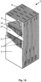
- FIG. 1 A preferred embodiment of a plate heat exchanger according to the invention is shown schematically and in perspective and designated 1.
- the plate heat exchanger 1 has a cuboid central body 8 with a length of, for example, several meters and a width or height of, for example, approximately one or a few meters.
- the central body 8 is an arrangement of alternating partition plates 20 and fins 11, 12 (so-called fins).
- the central body 8 of the plate heat exchanger 1 therefore has a plurality of partition plates and a plurality of fins, with a fin being arranged between each two adjacent partition plates.
- Both the partition plates and the fins can be made of, for example, aluminum.
- Sidebars 4 which can also be made of aluminum, are closed off, so that a side wall is formed by the stacked construction with the separating plates 20.
- the outer slats (here 11) of the central body 8 are closed off by a cover 5 (cover plate) lying parallel to the slats and the separating plates, usually also made of aluminum.
- the generally brazed separating plates 20, edge strips 4, and fins are stacked to form the central body 8 shown here, which is then brazed in a brazing furnace under vacuum. Subsequently, the inlet and outlet attachments 6, 6a required for the supply and discharge of the heat-exchanging fluids are attached, as shown in Figure 1B are shown.
- Attachments 6 and 6a located below the central body 8 and on the side opposite the illustrated side, are partially concealed.
- a fluid or process stream can be fed into or removed from the plate heat exchanger 1 through nozzles 7.
- the attachments 6 and 6a serve to distribute the fluid introduced through nozzles 7 and to collect and concentrate the fluid to be removed from the plate heat exchanger 1, respectively, with the distribution or collection being achieved via distributor fins 3 (see FIG. Figure 1A ) to or from the heat exchanger fins 11, 12.
- the various fluid flows then exchange thermal energy.
- the Plate heat exchanger 1 shown is designed to guide fluid streams past each other in separate passages for heat exchange. Some of the streams can be directed past each other in opposite directions, while others can be directed crosswise or in the same direction.
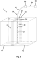
- At least one capillary with a plurality of thermo- or measuring resistance elements is in at least one separating plate 20 of the plurality of Partition plates are inserted as described below with respect to Figure 2 which shows a section of the plate heat exchanger 1 schematically and in perspective.
- slats 11 and 12 are arranged adjacent to a separating plate 20.
- the slats 11 and 12 are shown only very schematically, with their course being indicated on the lower surface of the section shown here.
- the channels formed by the slats 11 and 12 extend parallel to the section 31, which is described below.
- the separating plate 20 has two partial plates 21 and 22, in each of which a groove 23 or 24 is made.
- a capillary 30 is introduced into these (half) grooves 23 or 24 in the separating plate 20, in particular in such a way that the capillary 30 is completely enclosed or covered by the material of the first partial plate 21 and the second partial plate 22.
- the capillary 30 has a first section 31 within the separating plate 20 and a second section 32 outside the separating plate 20.
- a plurality of spaced-apart thermal or measuring resistance elements 40 are arranged in the capillary 30, by means of which temperature values along the longitudinal direction of the capillary 30 within the plate heat exchanger 1 can be recorded.
- the capillary 30 is designed in particular with thin walls in the first section 31, for example as a thin stainless steel tube, and is metallically encapsulated in the second section 32, i.e., encased in a metal or designed as a thicker tube.
- the capillary 30 is guided to a transfer point 50, which can be connected via cabling 51 to a computing unit 60, for example, a control unit.
- the computing unit 60 can receive and evaluate the temperature values recorded by the thermal or measuring resistance elements 40 and from there, for example, by means of a transmitter, send the resulting data to a cloud for further processing.
- the transfer point 50 can, for example, represent an interface between a process chamber in which the plate heat exchanger 1 is located and the outside world, so that the computing unit 60 is not arranged within the process chamber.
- this process chamber can be a furnace or brazing furnace during a manufacturing process of the plate heat exchanger 1 or a cold box during regular operation of the plate heat exchanger 1.
- the wiring in area 51 should ideally be continued from area 32 using the same material. Otherwise, unit 60 cannot measure the thermoelectric voltage correctly unless the temperature at transfer point 50 is also measured and the thermoelectric voltage corrected accordingly. Using measuring resistor elements can avoid such wiring problems.
- the plate heat exchanger 1 is manufactured and operated in particular according to a preferred embodiment of a method according to the invention, as described below with reference Figure 3 is explained, in which a preferred embodiment of a method according to the invention is shown schematically as a block diagram.
- a manufacturing process of the plate heat exchanger 1 is designated by 100. During the manufacturing process 100, a plurality of separating plates and a plurality of fins are first provided in a step 101.
- the partition plates correspond, for example, to those in Figure 2 shown partial plates 21 and 22, but each has no groove.
- a groove is milled into some of the separating plates to obtain partial plates 21 and 22 as shown in Figure 2
- a groove can be introduced into 25% of the plurality of partition plates.
- a capillary 30 is inserted between each two of the plates 21, 22 provided with grooves in step 102 in order to obtain a separating plate 20 with a capillary 30, as shown in Figure 2 is shown.
- separating plates 20 with capillary 30 are therefore twice as thick as separating plates without capillary, since the separating plates 20 with capillary 30 are each made from two such separating plates without capillary.
- a solder is applied to the surfaces of the separating plates in a process chamber, e.g., a furnace, and then the separating plates and lamellae are stacked alternately on top of one another.
- every fourth separating plate can be a separating plate 20 with a capillary 30, so that the adjacent separating plates (partial plates) must be connected by soldering.
- the individual capillaries 30 are each connected to a processing unit via a transfer point, and in step 106, the separating plates and the lamellae are integrally joined to one another in the furnace by soldering.
- step 107 temperature values within the plate heat exchanger are recorded using the thermal or measuring resistance elements 40 in the capillaries 30 and transmitted to the computing unit.
- step 108 the further soldering process is monitored based on or as a function of the recorded temperature values.
- a temperature distribution within the plate heat exchanger is monitored, expediently to prevent gaps from forming within the plate heat exchanger due to different thermal expansions during the soldering process and resulting deformation differences caused by loose or insufficiently firmly connected separating plates and fins.
- the attachments 6, 6a, nozzles 7, and cover are attached to the plate heat exchanger 1 in step 109.
- the capillaries 30 can be separated from the rake unit 60 in step 110.
- the capillaries 30 remain within the plate heat exchanger 1 and the thermo- or measuring resistance elements 40 can also be used during regular operation to record temperature values, as explained below.
- step 201 The regular operation of the plate heat exchanger 1 is in Figure 3 designated 200.
- step 201 the capillaries 30 are again connected to a computing unit, for example, a control unit.
- step 202 two fluids are Countercurrent through the plate heat exchanger 1 to achieve an indirect heat exchange.
- step 203 temperature values are recorded during this operation of the plate heat exchanger using the thermal or measuring resistance elements 40 in the capillaries 30.
- step 204 the operation of the plate heat exchanger 1 is controlled or regulated depending on these recorded temperature values. In particular, an optimization of the operation can be carried out in order to extend the remaining service life of the plate heat exchanger 1.
- a lifetime consumption or a remaining lifetime of the plate heat exchanger 1 is determined in step 205.
- thermal or mechanical stresses within the plate heat exchanger 1 can be determined from the temperature values, depending on which the lifetime consumption and the remaining lifetime of the plate heat exchanger 1 can be determined.
- step 206 the recorded temperature values are expediently archived in the computing unit in order to be available for comparison with temperature values recorded at a later time.
- the present invention thus makes it possible to measure temperature during the manufacturing process of the plate heat exchanger 1 during the soldering of the fins and the separating plates, and also during regular operation of the plate heat exchanger 1, using the same temperature measuring devices in the form of the thermal or measuring resistance elements 40 in capillaries 30.
- the thermal or measuring resistance elements 40 which are used during the manufacturing process to monitor the soldering, can also be used during regular operation.
Landscapes
- Engineering & Computer Science (AREA)
- Mechanical Engineering (AREA)
- Physics & Mathematics (AREA)
- Thermal Sciences (AREA)
- General Engineering & Computer Science (AREA)
- Chemical & Material Sciences (AREA)
- Materials Engineering (AREA)
- Heat-Exchange Devices With Radiators And Conduit Assemblies (AREA)
Description
- Die Erfindung betrifft ein Verfahren zum Herstellen eines Plattenwärmetauschers sowie einen Plattenwärmetauscher mit einer Vielzahl an Trennplatten und einer Vielzahl an Lamellen, wobei jeweils zwischen zwei benachbarten Trennplatten eine Lamelle angeordnet ist.
- Plattenwärmetauscher weisen eine Vielzahl an parallel zueinander angeordneten Trennplatten oder Trennbleche (engl. "seperator plates") und eine Vielzahl an Lamellen (sogenannter Fins) auf, wobei zwischen zwei benachbarten Trennplatten je eine Lamelle angeordnet ist, so dass eine Vielzahl von parallelen Kanälen zwischen benachbarten Platten gebildet wird, die von einem Medium durchfließbar sind. Zu den Seiten hin werden die Lamellen durch sogenannte Sidebars (Randleisten) begrenzt, die mit den angrenzenden Platten verlötet sind. Auf diese Weise wird eine Vielzahl an parallelen Wärmeübertragungspassagen gebildet, so dass Medien z.B. im Gegenstrom aneinander vorbeigeführt werden können, um einen indirekten Wärmeaustausch zu vollziehen.
- Thermische Spannungen infolge unterschiedlicher Wärmeausdehnungen aus differentiellen Temperaturunterschieden können zur mechanischen Schädigung der Dichtheit zwischen den Wärmeübertragungspassagen bis hin zur Undichtigkeit des Plattenwärmetauschers gegenüber seiner Umgebung führen. Zur Analyse des Temperaturfeldes kann ein derartiger Plattenwärmetauscher beispielsweise mit einer Temperaturmessung auf einer Oberfläche seiner Außenhaut ausgestattet sein. Die Temperaturen auf der Außenhaut liefern jedoch nur einen lokalen Wert, mit dem unter Annahmen auf die Temperatur im Inneren des Plattenwärmetauschers zurückgeschlossen werden kann. Diese Temperaturmessungen können jedoch aufgrund der Messung an der Außenhaut von Umwelteinflüssen beeinflusst werden.
- Die
WO 2014/056587 A1 beschreibt beispielsweise einen Plattenwärmetauscher mit einem Lichtwellenleiter zur Temperaturmessung. Der Lichtwellenleiter ist dabei in einer offenen Nut positioniert, die entweder in einer Lamelle oder in einem Trennblech des Plattenwärmetauschers vorgesehen ist. -
JP2014169809 A - Es ist wünschenswert, eine verbesserte Möglichkeit zur Temperaturmessung in Plattenwärmetauschern bereitzustellen.
- Vor diesem Hintergrund werden ein Verfahren zum Herstellen eines Plattenwärmetauschers sowie ein Plattenwärmetauscher mit einer Vielzahl an Trennplatten und einer Vielzahl an Lamellen, wobei jeweils zwischen zwei benachbarten Trennplatten eine Lamelle angeordnet ist, mit den Merkmalen der unabhängigen Patentansprüche vorgeschlagen. Vorteilhafte Ausgestaltungen sind Gegenstand der Unteransprüche sowie der nachfolgenden Beschreibung.
- Im Rahmen des vorliegenden Verfahrens zum Herstellen des Plattenwärmetauschers wird wenigstens eine Kapillare mit einer Vielzahl von Thermoelemente oder Messwiderstandselementen in wenigstens eine Trennplatte der Vielzahl von Trennplatten eingebracht. Jeweils abwechselnd werden eine Trennplatte der Vielzahl von Trennplatten und eine Lamelle der Vielzahl von Lamellen angeordnet und miteinander stoffschlüssig verbunden. Somit wird jeweils zwischen zwei parallel zueinander verlaufende Trennplatten eine Lamelle angeordnet.
- Der vorliegenden Erfindung liegt die Erkenntnis zu Grunde, eine Vielzahl von Thermoelementen oder ein Messwiderstandselementen in einer Kapillare in wenigstens eine Trennplatte des Plattenwärmetauschers einzubringen und zur Überwachung der Temperatur innerhalb des Plattenwärmetauschers, insbesondere schon bei dessen Herstellung, zu nutzen.
- Als ein Thermoelement sei in diesem Zusammenhang insbesondere ein Element verstanden, welches den sog. thermoelektrischen Effekt oder Seebeck-Effekt zur Messung einer Temperatur ausnutzt. Insbesondere umfasst ein Thermoelement zwei elektrische Leiter aus unterschiedlichen Metallen, welche an einem Ende miteinander verbunden sind, z.B. mittels einer Schweißverbindung. Als thermoelektrischer Effekt oder Seebeck-Effekt wird das Auftreten einer elektrischen Spannung bzw. einer Potentialdifferenz (sog. Thermospannung) auf Grund eines Temperaturgefälles entlang eines elektrischen Leiters bezeichnet. Diese elektrische Spannung bzw. Potentialdifferenz ist insbesondere abhängig von der Temperaturdifferenz entlang des Leiters und ferner insbesondere für jedes Leitermaterial unterschiedlich. In dem Thermoelement werden somit bei einer Temperaturdifferenz in den beiden aus unterschiedlichen Materialien gefertigten Leitern unterschiedliche Thermospannungen erzeugt. Die Verbindungsstelle, an welcher die beiden Leiter des Thermoelements an ihrem einen Ende miteinander verbunden sind, wird zweckmäßigerweise der zu messenden Temperatur ausgesetzt und auch als Messstelle bezeichnet. An ihren anderen, nicht miteinander verbundenen Enden (sog. Vergleichsstelle) werden die beiden Leiter insbesondere mit einem Spannungsmessgerät verbunden. Aus der an diesen Enden bzw. an dieser Vergleichsstelle abgreifbaren Spannungsdifferenz kann auf die Temperatur an der Messstelle rückgeschlossen werden.
- Alternativ (prinzipiell aber auch zusätzlich) kann eine Vielzahl von Messwiderstandselementen in einer Kapillare in wenigstens eine Trennplatte des Plattenwärmetauschers eingebracht und zur Überwachung der Temperatur innerhalb des Plattenwärmetauschers, insbesondere schon bei dessen Herstellung, genutzt werden. Messwiderstandselemente sind an sich bekannt und werden auch als temperaturabhängige Widerstände oder Widerstandsthermometer bezeichnet. Es handelt sich um elektrische Bauelemente, die die Temperaturabhängigkeit des elektrischen Widerstands eines elektrischen Leiters zur Messung der Temperatur ausnutzen. Als elektrischer Leiter werden in der Regel reine Metalle, insbesondere aber korrosionsbeständiges Platin, eingesetzt. Vorteil ist hierbei auch der nahezu lineare Zusammenhang zwischen Temperatur und Widerstand. Platin-Widerstandsthermometer können in entsprechender Ausführung bis zu 1000°C verwendet werden. Bekannt sind genormte Platin-Messwiderstände wie Pt100 oder Pt1000, bei denen der Nennwiderstand R0 bei 0°C 100 Ohm bzw. 1 kOhm beträgt. Zur Widerstandsmessung wird im einfachsten Fall der Spannungsabfall an dem von einem konstanten Messstrom durchflossenen Messwiderstand gemessen, wobei hierfür zumeist eine Wheatstone-Brücke in einer Zweileiter-Schaltung verwendet wird. Um den Einfluss langer Zuleitungen zu dem Sensor auf den Messwert zu vermieden, sind Drei- oder Vierleiter-Schaltungen bekannt. Hierdurch sind bei entsprechend höherem Platzbedarf deutlich höhere Genauigkeiten insbesondere unabhängig vom verwendeten Anschlusskabelmaterial zu erreichen.
- Thermoelemente als auch Messwiderstandselemente weisen eine hohe Hitzebeständigkeit auf und ermöglichen es auch bei hohen Temperaturen präzise Messwerte zu erfassen. Daher eignen sich Thermo- und Messwiderstandselemente besonders, um bereits während des Herstellungsprozesses des Plattenwärmetauschers verwendet zu werden, da sie den beim stoffschlüssigen Verbinden auftretenden hohen Temperaturen standhalten und dabei eine präzise Erfassung von Temperaturwerten bzw. Temperaturmesswerten ermöglichen. Insbesondere sind Thermo- und Messwiderstandselemente wesentlich hitzebeständiger als herkömmliche Lichtwellenleiter. Daher können herkömmliche Lichtwellenleiter üblicherweise während des Herstellungsprozesses eines Plattenwärmetauschers nicht eingesetzt werden, da sie den dabei auftretenden hohen Temperaturen nicht standhalten würden. Zwar mag die Möglichkeit bestehen, hochtemperaturbeständige Lichtwellenleiter zu verwenden, welche derartig hohen Temperaturen ausgesetzt werden können, jedoch sind derartige hochtemperaturbeständige Lichtwellenleiter sehr kostenintensiv. Im Gegensatz dazu kann mit Hilfe von Thermo- oder Messwiderstandselementen auf wesentliche günstigere Weise eine Temperaturerfassung bzw. Temperaturüberwachung nicht nur während des Betriebs, sondern auch während des Herstellungsprozesses des Plattenwärmetauschers ermöglicht werden.
- Erfindungsgemäß ist pro Kapillare eine Vielzahl von Thermo- oder Messwiderstandselementen angeordnet. Die derart ausgebildete Kapillare wird im Folgenden als "Thermoelement-Profilstab" bzw. als "Messwiderstandselement-Profilstab" bezeichnet. Diese Thermo- oder Messwiderstandselemente in der Kapillare sind zweckmäßigerweise in geeigneten Abständen zueinander angeordnet, um die Temperatur innerhalb des Plattenwärmetauschers an den entsprechenden Stellen entlang des Profilstabs, also entlang der Längsausdehnung der Kapillare, effektiv erfassen zu können, insbesondere um Temperaturunterschiede bzw. eine Temperaturverteilung bzw. ein Temperaturfeld erfassen zu können. Ferner ist insbesondere in einer Vielzahl von Trennplatten, insbesondere in mindestens 10%, vorzugsweise mindestens 20%, 25%, 30%, 40% oder mindestens 50% der Trennplatten, jeweils eine derartige Kapillare angeordnet. Insbesondere sind die Trennplatten mit Kapillare in geeigneten Abständen zueinander angeordnet, um effektiv die Temperatur innerhalb des Plattenwärmetauschers zu erfassen und um ferner insbesondere Temperaturunterschiede bzw. eine Temperaturverteilung bzw. ein Temperaturfeld erfassen zu können. Insbesondere kann es somit ermöglicht werden, auf kleinem Bauraum Temperaturprofile in dem Plattenwärmetauscher zu erfassen.
- Die speziellen Typen von Thermo- oder Messwiderstandselementen in der Kapillare können insbesondere gemäß den spezifischen Eigenschaften dieser Typen und ferner insbesondere in Abhängigkeit von den Bedingungen in dem jeweiligen Plattenwärmetauscher gewählt werden. Thermoelement-Typen beschreiben zweckmäßigerweise die Kombination der Materialen der beiden in dem jeweiligen Thermoelement verwendeten Leiter. Beispielsweise können im Rahmen des vorliegenden Verfahrens Thermoelemente vom Typ K verwendet werden (mit einem Leiter aus NiCr und dem anderen aus Ni) und/oder vom Typ J (mit Leitern aus Fe und CuNi) und/oder vom Typ L (mit Leitern aus Fe und CuNi). Messwiderstandselemente sind bevorzugt Pt100- oder Pt1000-Messwiderstände, wobei je nach Genauigkeitsanforderungen und Platzbegrenzung Zwei-, Drei- oder Vierleiter-Schaltungen verwendet werden.
- Vorzugsweise werden während des stoffschlüssigen Verbindens bei der Herstellung des Plattenwärmetauschers mit Hilfe der Vielzahl von Thermo- oder Messwiderstandselementen der wenigstens einen Kapillare Temperaturwerte erfasst und das stoffschlüssige Verbinden wird anhand der bzw. in Abhängigkeit von den erfassten Temperaturwerten überwacht. Aufgrund seiner hohen Hitzebeständigkeit kann mit Hilfe der Vielzahl von-Thermo- oder Messwiderstandselementen die Temperatur innerhalb des Plattenwärmetauschers während dessen Herstellungsprozesses bzw. während des stoffschlüssigen Verbindens der Trennplatten und der Lamellen präzise erfasst und überwacht werden. Im Gegensatz zu Lichtwellenleitern kann mit Hilfe von Thermo- oder Messwiderstandselementen auf einfache Weise eine Temperaturerfassung und Temperaturüberwachung sogar während des Herstellungsprozesses des Plattenwärmetauschers ermöglicht werden. Insbesondere kann der Prozess des stoffschlüssigen Verbindens in Abhängigkeit von den erfassten Temperaturwerten durchgeführt bzw. gesteuert und/oder geregelt werden. Beispielsweise kann in Abhängigkeit von den erfassten Temperwerten überwacht werden, ob die Trennbleche bzw. Lamellen im Zuge des Verbindungsprozesses ausreichend hoch erhitzt wurden, um eine gewünschte Festigkeit bzw. Stärke der Verbindung zu erreichen, und/oder ob beim Verbindungsprozess Temperaturgradienten auftreten, die die Dauerhaftigkeit bzw. Festigkeit der Verbindung gefährden könnten.
- Vorteilhafterweise werden die Trennplatten und die Lamellen jeweils mittels eines Lötprozesses miteinander stoffschlüssig verbunden, vorzugsweise mittels eines Vakuum-Lötprozesses. Beispielsweise kann zu diesem Zweck ein Lot auf die Flächen der Trennbleche aufgebracht werden und anschließend können die Trennbleche und die Lamellen mit den seitlich abschließend angeordneten Randleisten (Sidebars) abwechselnd aufeinander gestapelt werden. Anschließend wird der Plattenwärmetauscher bzw. dessen Zentralkörper durch Erhitzen in einem Ofen verlötet. Bei einem derartigen Löten kann beim Aufheizen bzw. Abkühlen eine ungleichmäßige Temperaturverteilung innerhalb des Plattenwärmetauschers entstehen. Dies kann aufgrund der unterschiedlichen thermischen Dehnungen und der daraus resultierenden Verformungsunterschiede zu Spaltbildungen innerhalb des Plattenwärmetauschers durch lose oder noch nicht ausreichend fest verbundene Lamellen und Trennbleche führen. Besonders bevorzugt wird daher während des Lötprozesses mit Hilfe der Vielzahl von Thermo- oder Messwiderstandselements in der wenigstens einen Kapillare Temperaturwerte erfasst und das Löten wird anhand der erfassten Temperaturwerte überwacht und ferner vorzugsweise in Abhängigkeit von den erfassten Temperaturwerten gesteuert bzw. geregelt. Durch das aufwandsarme und präzise Erfassen der Temperaturwerte mit Hilfe der Thermo- oder Messwiderstandselemente kann daher die Temperaturverteilung und ferner insbesondere ein Temperaturfeld bzw. Temperaturunterschiede innerhalb des Plattenwärmetauschers während des Lötens bestimmt und überwacht werden. Insbesondere kann somit überwacht und verhindert werden, dass es aufgrund unterschiedlicher thermischer Dehnungen zu Spaltbildungen innerhalb des Plattenwärmetauschers kommt.
- Vorteilhafterweise wird die wenigstens eine Kapillare in eine Nut in der wenigstens einen Trennplatte eingebracht. Diese Nut kann insbesondere derart in einem Inneren der Trennplatte vorgesehen sein, dass die Kapillare zweckmäßigerweise vollständig von dem Material der Trennplatte umschlossen bzw. abgedeckt ist. Insbesondere kann die Nut im Zuge des Herstellungsprozesses des Plattenwärmetauschers in die wenigstens eine Trennplatte eingebracht werden, beispielsweise mittels Fräsens. Anschließend kann die Kapillare zweckmäßigerweise in die hergestellte Nut eingebracht werden. Ebenso ist es denkbar, dass die wenigstens eine Trennplatte bereits mit der entsprechenden Nut von einem entsprechenden Hersteller bezogen wird und im Zuge des Herstellungsprozesses nur die Kapillare in die Nut eingebracht wird.
- Vorzugsweise wird die wenigstens eine Trennplatte, die die Kapillare mit der Vielzahl von Thermo- oder Messwiderstandselement aufweist, aus einer ersten Teilplatte und einer zweiten Teilplatte mit aneinandergrenzenden Flächen gebildet. Als Teilplatten können dabei insbesondere Trennplatten verwendet werden, also Trennplatten, wie sie im Übrigen bei der Herstellung des Plattenwärmetauschers verwendet werden. Es werden dann zwei statt einer Trennplatte eingesetzt und die Kapillare dort angeordnet.
- Insbesondere wird vorzugsweise die Nut in zumindest eine der beiden einander zugewandten angrenzenden Flächen der ersten und zweiten Teilplatte eingebracht. Die Nut kann beispielsweise durch Fräsen entstehen. Entweder wird die Nut nur in eine Teilplatte eingebracht oder insbesondere zu gleichen Teilen (zwei "Halbnuten") in beide aneinandergrenzende Flächen der Teilplatten.
- Insbesondere ist die Kapillare dabei derart in die Nut eingebracht, dass sie vollständig von dem Material der ersten Teilplatte und der zweiten Teilplatte umschlossen bzw. abgedeckt ist. Analog zu obiger Erläuterung können die Nuten insbesondere im Zuge des Herstellungsprozesses des Plattenwärmetauschers in die Teilplatten beispielsweise durch Fräsen eingebracht werden oder es können zweckmäßigerweise auch bereits mit Nuten versehene Teilplatten bezogen werden. Die Teilplatten können sich dabei andrerseits auch von den Trennplatten, in welchen keine Kapillaren eingebracht sind, unterscheiden und beispielsweise nur halb so dick wie diese Trennplatten sein. Besonders bevorzugt ist es denkbar, dass als erste und zweite Trennplatte jeweils eine der Trennplatten des Plattenwärmetauschers verwendet wird, in welche sonst keine Kapillare eingesetzt ist. Im Zuge des Herstellungsprozesses des Plattenwärmetauschers kann dabei insbesondere in zwei derartige Trennplatten jeweils eine Halbnut eingebracht werden, z.B. durch Fräsen. Die entsprechende Kapillare kann nach Aufeinanderlegen der entsprechenden Flächen der Trennplatten in die so entstehende Vollnut eingebracht werden und die beiden Trennplatten können dann miteinander stoffschlüssig verbunden werden, beispielsweise durch Löten oder Schweißen.
- Bevorzugt ist die wenigstens eine Kapillare außerhalb der wenigstens einen Trennplatte metallisch gekapselt bzw. als metallische Kapsel ausgebildet bzw. mit einem geeigneten Metall umhüllt. Insbesondere weist die Kapillare somit einen ersten Teilbereich bzw. Abschnitt innerhalb der Trennplatte und einen zweiten Teilbereich bzw. Abschnitt außerhalb der Trennplatte auf. Alternativ oder zusätzlich ist die wenigstens eine Kapillare vorzugsweise innerhalb der wenigstens einen Trennplatte dünnwandig ausgebildet. Die Kapillare ist somit insbesondere in ihrem ersten Teilbereich nicht metallisch gekapselt.
- Bevorzugt wird die wenigstens eine Kapillare aus einer Prozesskammer hinaus geführt, in welcher das stoffschlüssige Verbinden durchgeführt wird, insbesondere aus einem (Vakuum-)Ofen zum Verlöten. Insbesondere durch die metallische Kapselung im genannten zweiten Teilbereich außerhalb der Trennplatte kann somit verhindert werden, dass während des Verbindungsprozesses Ausdampfungen in die Prozesskammer bzw. den Ofenraum abgegeben werden.
- Es versteht sich, dass der Herstellungsprozess des Plattenwärmetauschers noch weitere zweckmäßige Schritte umfassen kann, bis der Plattenwärmetauscher in Betrieb genommen werden kann. Erfindungsgemäß werden die Lamellen zu den Seiten hin durch sogenannte Sidebars (Randleisten) begrenzt, die mit den angrenzenden Trennplatten stoffschlüssig verbunden werden, z.B. durch Löten. Auf diese Weise wird zweckmäßigerweise eine Vielzahl an parallelen Wärmeaustauschpassagen gebildet, durch welche im regulären Betrieb des Plattenwärmetauschers zum indirekten Wärmetausch zwei Fluide bzw. Medien geleitet werden können. Besonders vorteilhaft wird die wenigstens eine Kapillare mit der Vielzahl von Thermo- oder Messwiderstandselementen im späteren Verlauf des Herstellungsprozesses und auch nach komplett durchgeführtem Herstellungsprozess nicht aus der wenigstens einen Trennplatte entfernt. Die wenigstens eine Kapillare mit der Vielzahl von Thermo- oder Messwiderstandselementen verbleibt somit auch nach dem Herstellungsprozess in dem Plattenwärmetauscher und kann zweckmäßigerweise im regulären Betrieb desselben verwendet werden.
- Wenn eine Kapillare mit der Vielzahl von Thermo- oder Messwiderstandselementen beim Lötprozess in eine Nut eingelegt ist, wird diese Kapillare während des Lötens vom Lot umschlossen und kann danach (bspw. für den Fall von Reparaturen oder dergleichen) nicht mehr entfernt werden. Um dies zu vermeiden, müsste eine größere Kapillare bspw. aus Edelstahl oder einem anderen Material mit deutlich höherem Schmelzpunkt als Aluminium in die Nut eingelegt werden. Der Innenraum dieser größeren Kapillare bleibt lotfrei, so dass eine Temperaturmesseinrichtung mit Messelement ein- und wieder ausgeführt werden kann. Das gleiche Vorgehen ist auch notwendig, wenn die Temperaturmesseinrichtung nicht während des Lötprozesses im Plattenwärmetauscher sein soll. Hätte man dann nur eine leere Nut, würde diese mit Lot gefüllt werden. Auch hier muss folglich eine größere Kapillare mit eingelötet werden, die dann den Platz für die Temperaturmesseinrichtung freihält. Hierfür kann beispielsweise ein temperaturstabiles Edelstahlröhrchen mit möglichst geringer Wandstärke genutzt werden (bspw. 0,2mm), um den erforderlichen Querschnitt sicherzustellen.
- Eine besonders bevorzugte Ausführungsform der Erfindung betrifft ein Verfahren zum Betreiben eines Plattenwärmetauschers, der gemäß einer bevorzugten Ausführungsform des erfindungsgemäßen Verfahrens hergestellt wurde. Im Zuge dieses Betriebs werden ein erstes Fluid und ein zweites Fluid durch den Plattenwärmetauscher geleitet, insbesondere durch die Wärmeaustauschpassagen, welche durch die miteinander verbundenen Lamellen und Trennbleche, seitlich begrenzt durch die Randleisten (Sidebars), gebildet werden. Zweckmäßigerweise werden diese beiden Fluide im Gegenstrom aneinander vorbeigeführt und können insbesondere einen indirekten Wärmeaustausch vollziehen. Während dieses Betriebs des Plattenwärmetauschers werden besonders vorteilhaft mit Hilfe der Vielzahl von Thermo- oder Messwiderstandselements in der wenigstens einen Kapillare Temperaturwerte erfasst. Somit wird es ermöglicht, Temperaturerfassung während des stoffschlüssigen Verbindungsprozesses der Lamellen und der Trennbleche und ferner während des regulären Betriebs des Plattenwärmetauschers mit denselben Temperaturmesseinrichtungen in Form des wenigstens einen Thermo- oder Messwiderstandselements, also insbesondere mittels eines oder mehrerer der oben definierten Thermo- oder Messwiderstandselement-Profilstäbe, durchzuführen. Die Thermo- oder Messwiderstandselemente, welche im Zuge des Herstellungsprozesses zum Überwachen des stoffschlüssigen Verbindungsprozesses, vorzugsweise des Lötens bzw. Vakuum-Lötens, verwendet werden, können somit auch im regulären Betrieb des Plattenwärmetauschers noch weiter verwendet werden, um Temperaturwerte zu erfassen, insbesondere um Temperaturunterschiede bzw. eine Temperaturverteilung bzw. ein Temperaturfeld innerhalb des Plattenwärmetauschers zu ermitteln. Insbesondere ist es somit nicht notwendig, für den regulären Betrieb zusätzliche Temperaturmessvorrichtungen vorzusehen, wodurch Kosten und Aufwand eingespart werden können.
- Gemäß einer bevorzugten Ausführungsform wird der Betrieb des Plattenwärmetauschers in Abhängigkeit von den während des Betriebs des Plattenwärmetauschers erfassten Temperaturwerten gesteuert und/oder geregelt. Insbesondere können die aktuell erfassten Temperaturwerte somit verwendet werden, um einen effektiven, bestmöglichen Betrieb des Plattenwärmetauschers zu ermöglichen. Ferner werden die erfassten Temperaturwerte insbesondere verwendet, um eine Optimierung des Betriebs bzw. der Betriebsweise des Plattenwärmetauschers vorzunehmen, zweckmäßigerweise auch um die verbleibende Lebensdauer des Plattenwärmetauschers verlängern zu können.
- Vorteilhafterweise werden in Abhängigkeit von den während des Betriebs des Plattenwärmetauschers erfassten Temperaturwerten ein Lebensdauerverbrauch und/oder eine verbleibende Lebensdauer des Plattenwärmetauschers bestimmt. Die aktuell erfassten Temperaturwerte werden zu diesem Zweck ausgewertet und können dabei beispielsweise mit gespeicherten Daten bzw. zu früheren Zeitpunkten erfassten Temperaturwerten verglichen werden und/oder beispielsweise als Eingangsdaten für ein theoretisches Modell bzw. eine Simulation des Plattenwärmetauschers verwendet werden. Mittels der innerhalb des Plattenwärmetauschers angeordneten Thermo- oder Messwiderstandselemente können somit Temperaturwerte im Inneren des Plattenwärmetauschers erfasst werden, was eine besonders effektive und aufwandswarme Überwachung der Lebendsauer ermöglicht. Insbesondere können aus den Temperaturwerten thermische bzw. mechanische Spannungen innerhalb des Plattenwärmetausches abgeleitet werden, in Abhängigkeit von welchen der Lebensdauerverbrauch und/oder die verbleibende Lebensdauer des Plattenwärmetauschers zweckmäßigerweise bestimmt werden können. Ferner können die aktuell erfassten Temperaturwerte zweckmäßigerweise auch archiviert und beispielsweise in einer Steuereinheit hinterlegt werden, um für einen Vergleich mit zu einem späteren Zeitpunkt erfassten Temperaturwerten und somit für einen zukünftige Bestimmung des Lebensdauerverbrauchs und/oder der verbleibenden Lebensdauer verwendet zu werden.
- Vorzugsweise wird in Abhängigkeit von den während des Betriebs des Plattenwärmetauschers erfassten Temperaturwerten eine Betriebshistorie des Plattenwärmetauschers bestimmt. Als Betriebshistorie seien in diesem Zusammenhang insbesondere Prozesse, Prozessveränderungen bzw. Gegebenheiten in dem Plattenwärmetauscher zu verstehen, welche sich auf den Lebensdauerverbrauch bzw. auf die verbleibende Lebensdauer des Plattenwärmetauschers auswirken. Insbesondere betrifft die Betriebshistorie von dem Plattenwärmetauscher durchgeführte Lastwechsel, also insbesondere Prozesse, im Zuge derer sich die in dem Plattenwärmetauscher auftretenden mechanischen Spannungen verändern. Insbesondere werden als Betriebshistorie in Abhängigkeit von den während des Betriebs des Plattenwärmetauschers erfassten Temperaturwerten eine Anzahl von durchgeführten Lastwechseln bestimmt und/oder eine Geschwindigkeit, mit welcher einzelne Lastwechsel durchgeführt werden.
- Ein erfindungsgemäßer Plattenwärmetauscher weist eine Vielzahl an Trennplatten und eine Vielzahl an Lamellen auf, wobei jeweils zwischen zwei benachbarten Trennplatten der Vielzahl von Trennplatten eine Lamelle der Vielzahl von Lamellen angeordnet ist, wobei jeweils abwechselnd eine Trennplatte und eine Lamelle angeordnet und miteinander stoffschlüssig verbunden sind, wobei die Lamellen zu den Seiten hin durch Randleisten begrenzt sind, und wobei die Randleisten mit den angrenzenden Trennplatten stoffschlüssig verbunden sind, wobei wenigstens eine Kapillare mit wenigstens einem Thermo- und/oder Messwiderstandselement in wenigstens einer der Trennplatten eingebracht ist. Erfindungsgemäß sind pro Kapillare eine Vielzahl von Thermo- oder Messwiderstandselementen angeordnet. Vorteile und bevorzugte Ausgestaltungen des erfindungsgemäßen Verfahrens und des erfindungsgemäßen Plattenwärmetauschers ergeben sich aus der vorliegenden Beschreibung in analoger Weise.
- Bei einem erfindungsgemäßen Plattenwärmetauscher ist vorzugsweise die wenigstens eine Trennplatte aus einer ersten Teilplatte und einer zweiten Teilplatte mit aneinandergrenzenden Flächen gebildet, wobei eine Nut in zumindest eine der beiden angrenzenden Flächen der ersten und zweiten Teilplatte eingebracht ist und wobei die wenigstens eine Kapillare in der Nut angeordnet ist.
- Ein erfindungsgemäßer Plattenwärmetauscher ist insbesondere gemäß einer bevorzugten Ausführungsform des erfindungsgemäßen Verfahrens hergestellt.
- Ferner ist der Plattenwärmetauscher vorzugsweise dazu eingerichtet, gemäß einer bevorzugten Ausführungsform des erfindungsgemäßen Verfahrens wie obig erläutert betrieben zu werden. Insbesondere kann zu diesem Zweck eine Steuereinheit vorgesehen sein, beispielsweise in Form einer speicherprogrammierbaren Steuerung (SPS), welche, insbesondere programmtechnisch, dazu eingerichtet ist, eine bevorzugte Ausführungsform eines erfindungsgemäßen Verfahrens durchzuführen. Insbesondere kann diese Steuereinheit die während des Betriebs des Plattenwärmetauschers mit Hilfe der Vielzahl von Thermo- oder Messwiderstandselementen der wenigstens einen Kapillare erfassten Temperaturwerte empfangen und zweckmäßigerweise abspeichern und/oder auswerten, insbesondere um den Plattenwärmetauscher entsprechend zu steuern bzw. zu regeln und/oder um den Lebensdauerverbrauch bzw. die verbleibende Lebensdauer zu bestimmen und/oder um die Betriebshistorie zu bestimmen.
- Weitere Vorteile und Ausgestaltungen der Erfindung ergeben sich aus der Beschreibung und der beiliegenden Zeichnung.
- Weitere mögliche Ausgestaltungen der Erfindung umfassen auch nicht explizit genannte Kombinationen von zuvor oder im Folgenden bezüglich der Ausführungsbeispiele beschriebenen Merkmalen. Dabei wird der Fachmann auch hier beschriebene Einzelaspekte als Verbesserungen oder Ergänzungen zu den jeweiligen Ausführungsformen des erfindungsgemäßen Plattenwärmetauschers oder des erfindungsgemäßen Verfahrens hinzufügen.
- Die Erfindung ist anhand von Ausführungsbeispielen in der Zeichnung schematisch dargestellt und wird im Folgenden unter Bezugnahme auf die Zeichnung beschrieben.
-
- Figur 1
- zeigt schematisch und perspektivisch eine bevorzugte Ausgestaltung eines erfindungsgemäßen Plattenwärmetauschers vor (
Fig. 1A ) und nach dem Anbringen der Ein- und Auslassaufsätze (Fig. 1B ), der gemäß einer bevorzugten Ausführungsform eines erfindungsgemäßen Verfahrens hergestellt wurde und betrieben werden kann. - Figur 2
- zeigt schematisch einen Ausschnitt einer bevorzugten Ausgestaltung eines erfindungsgemäßen Plattenwärmetauschers.
- Figur 3
- zeigt schematisch eine bevorzugte Ausführungsform eines erfindungsgemäßen Verfahrens als ein Blockdiagramm.
- In
Figur 1 ist eine bevorzugte Ausgestaltung eines erfindungsgemäßen Plattenwärmetauschers schematisch und perspektivisch dargestellt und mit 1 bezeichnet. - Der Plattenwärmetauscher 1 gemäß
Figur 1A weist einen quaderförmigen Zentralkörper 8 mit einer Länge von beispielsweise mehreren Metern und einer Breite bzw. Höhe von beispielsweise etwa einem bzw. wenigen Metern auf. Im Wesentlichen handelt es sich bei dem Zentralkörper 8 um eine Anordnung aus sich abwechselnden Trennplatten 20 und Lamellen 11, 12 (sog. Fins). Der Zentralkörper 8 des Plattenwärmetauschers 1 weist also eine Vielzahl an Trennplatten und eine Vielzahl an Lamellen auf, wobei jeweils zwischen zwei benachbarten Trennplatten eine Lamelle angeordnet ist. Sowohl die Trennbleche als auch die Lamellen können beispielsweise aus Aluminium gefertigt sein. Zu ihren Seiten sind die Lamellen 11, 12 durch Randleisten (Sidebars) 4, die ebenfalls aus Aluminium gefertigt sein können, abgeschlossen, so dass durch die Stapelbauweise mit den Trennplatten 20 eine Seitenwand ausgebildet wird. Die außenliegenden Lamellen (hier 11) des Zentralkörpers 8 sind durch eine parallel zu den Lamellen und den Trennblechen liegende Abdeckung 5 (Deckblech) in der Regel ebenfalls aus Aluminium abgeschlossen. - Zur Herstellung des Plattenwärmetauschers 1 werden die in der Regel lotplattierten Trennbleche 20, Randleisten 4 und Lamellen (hier nur die Lamellen 11 und 12 bezeichnet) in einem Stapel zu dem hier dargestellten Zentralkörper 8 aufeinander gelegt, der dann in einem Lötofen unter Vakuum verlötet wird. Anschließend werden die zur Zu- und Ableitung der wärmetauschenden Fluide benötigten Ein- und Auslassaufsätze 6, 6a angebracht, wie sie in
Figur 1B gezeigt sind. - Oben auf dem Zentralkörper 8, an dessen Seiten und unterhalb des Zentralkörpers 8 erkennt man in
Figur 1B Aufsätze 6 und 6a. Die unterhalb des Zentralkörpers 8 und auf der der abgebildeten Seite abgewandten Seite befindlichen Aufsätze 6 und 6a sind teilweise verdeckt. - Durch Stutzen 7 kann dem Plattenwärmetauscher 1 ein Fluid bzw. Prozessstrom zugeführt bzw. diesem wieder entnommen werden. Die Aufsätze 6 und 6a dienen zur Verteilung des durch die Stutzen 7 eingebrachten Fluids bzw. zum Sammeln und zur Konzentration des aus dem Plattenwärmetauscher 1 zu entnehmenden Fluids, wobei die Verteilung bzw. das Sammeln über Verteilerlamellen ("distributor fins") 3 (vgl.
Figur 1A ) zu bzw. von den Wärmetauscher-Lamellen 11,12 erfolgt. Innerhalb des Plattenwärmetauschers 1 tauschen dann die verschiedenen Fluidströme Wärmeenergie aus. - Der in
Figur 1 gezeigte Plattenwärmetauscher 1 ist dazu ausgelegt, Fluidströme in getrennten Passagen zum Wärmeaustausch aneinander vorbeizuführen. Ein Teil der Ströme kann gegensinnig aneinander vorbeigeführt werden, ein anderer Teil über Kreuz oder gleichsinnig. - Wenigstens eine Kapillare mit einer Vielzahl von Thermo- oder Messwiderstandselementen ist in wenigstens eine Trennplatte 20 der Vielzahl von Trennplatten eingebracht, wie nachfolgend in Bezug auf
Figur 2 erläutert wird, welche einen Ausschnitt des Plattenwärmetauschers 1 schematisch und perspektivisch zeigt. - Wie in
Figur 2 zu erkennen ist, sind benachbart zu einer Trennplatte 20 Lamellen 11 und 12 angeordnet. Die Lamellen 11 und 12 sind lediglich sehr schematisch dargestellt, indem ihr Verlauf auf der unteren Fläche des hier dargestellten Ausschnitts angedeutet ist. Die durch die Lamellen 11 und 12 gebildeten Kanäle erstrecken sich parallel zum Abschnitt 31, der im Folgenden beschrieben ist. Die Trennplatte 20 weist zwei Teilplatten 21 und 22 auf, in welche jeweils eine Nut 23 bzw. 24 eingebracht ist. In diesen (Halb-)Nuten 23 bzw. 24 ist eine Kapillare 30 in die Trennplatte 20 eingebracht, insbesondere derart, dass die Kapillare 30 vollständig von dem Material der ersten Teilplatte 21 und der zweiten Teilplatte 22 umschlossen bzw. abgedeckt ist. Es ist auch möglich, nur eine Nut in nur eine der Teilplatten 21, 22 einzubringen, in die dann die Kapillare eingefügt wird. Als Teilplatten 21, 22 können beispielsweise übliche Trennplatten bzw. Trennbleche verwendet werden. Insbesondere weist die Kapillare 30 dabei einen ersten Abschnitt 31 innerhalb der Trennplatte 20 auf und einen zweiten Abschnitt 32 außerhalb der Trennplatte 20. In dem ersten Abschnitt 31 innerhalb der Trennplatte 20 ist in der Kapillare 30 eine Vielzahl von zueinander beabstandeten Thermo- oder Messwiderstandselementen 40 angeordnet ("Thermo- oder Messwiderstandselement-Profilstab"), mittels welcher Temperaturwerte entlang der Längsrichtung der Kapillare 30 innerhalb des Plattenwärmetauschers 1 erfasst werden können. Die Kapillare 30 ist in dem ersten Abschnitt 31 insbesondere dünnwandig ausgestaltet, bspw. als dünnes Edelstahlröhrchen, und in dem zweiten Abschnitt 32 metallisch gekapselt, also mittels eines Metalls umhüllt oder als dickeres Röhrchen ausgeführt. - Außerhalb der Trennplatte 20 ist die Kapillare 30 zu einem Übergabepunkt 50 geführt, welcher über eine Verkabelung 51 mit einer Recheneinheit 60, beispielsweise einer Steuereinheit verbunden werden kann. Insbesondere kann die Recheneinheit 60 die von den Thermo- oder Messwiderstandselementen 40 erfassten Temperaturwerte empfangen und auswerten und von dort bspw. mittels eines Senders die Ergebnisdaten an eine Cloud zur weiteren Verarbeitung senden. Der Übergabepunkt 50 kann beispielsweise eine Schnittstelle zwischen einer Prozesskammer, in welcher sich der Plattenwärmetauscher 1 befindet, und der Außenwelt darstellen, so dass die Recheneinheit 60 insbesondere nicht innerhalb der Prozesskammer angeordnet werden muss. Beispielsweise kann diese Prozesskammer ein Ofen bzw. Lötofen während eines Herstellungsprozess des Plattenwärmetauschers 1 sein oder ein Coldbox während des regulären Betriebs des Plattenwärmetauschers 1.
- Falls es sich bei den Messelementen um Thermoelemente handelt, muss die Verkabelung im Bereich 51 optimaler Weise materialgleich vom Bereich 32 fortgesetzt werden. Andernfalls kann die Einheit 60 die Thermospannung nicht korrekt messen, es sei denn, die Temperatur an dem Übergabepunkt 50 würde auch gemessen und die Thermospannung entsprechend korrigiert. Bei Verwendung von Messwiderstandelementen können derartige Leitungsanschlussprobleme vermieden werden.
- Der Plattenwärmetauscher 1 wird insbesondere gemäß einer bevorzugten Ausführungsform eines erfindungsgemäßen Verfahrens hergestellt und betrieben, wie nachfolgend in Bezug
Figur 3 erläutert wird, in welcher eine bevorzugte Ausführungsform eines erfindungsgemäßen Verfahrens schematisch als ein Blockdiagramm dargestellt ist. - Ein Herstellungsprozess des Plattenwärmetauscher 1 ist dabei mit 100 bezeichnet. Im Zuge des Herstellungsprozess 100 wird zunächst in einem Schritt 101 eine Vielzahl an Trennplatten und eine Vielzahl an Lamellen bereitgestellt.
- Die Trennplatten entsprechen beispielsweise den in
Figur 2 dargestellten Teilplatten 21 und 22, weisen jedoch jeweils keine Nut auf. In einige der Trennplatten wird in Schritt 102 eine Nut gefräst, um Teilplatten 21 und 22 zu erhalten, wie sie inFigur 2 dargestellt sind. Beispielsweise kann in 25% der Vielzahl von Trennplatten jeweils eine Nut eingebracht werden. - In Schritt 103 wird jeweils zwischen zwei der in Schritt 102 mit Nuten versehenen Platten 21, 22 jeweils eine Kapillare 30 eingebracht, um jeweils eine Trennplatte 20 mit Kapillare 30 zu erhalten, wie sie in
Figur 2 gezeigt ist. In diesem Beispiel sind Trennplatten 20 mit Kapillare 30 daher doppelt so dick wie Trennplatten ohne Kapillare, da die Trennplatten 20 mit Kapillare 30 aus je zwei derartigen Trennplatten ohne Kapillare gefertigt sind. - In Schritt 104 wird in einer Prozesskammer, z.B. einem Ofen, ein Lot auf die Flächen der Trennbleche aufgebracht und anschließend werden Trennbleche und Lamellen abwechselnd aufeinander gestapelt. Beispielsweise kann dabei jedes vierte Trennblech ein Trennblech 20 mit Kapillare 30 sein, so dass hier die aneinandergrenzenden Trennplatten (Teilplatten) durch Löten verbunden werden müssen. Nach dem Stapeln werden in Schritt 105 die einzelnen Kapillaren 30 über einen Übergabepunkt jeweils mit einer Recheneinheit verbunden und in Schritt 106 werden die Trennbleche und die Lamellen in dem Ofen mittels Löten miteinander stoffschlüssig verbunden.
- Während des Lötens werden in Schritt 107 mit Hilfe der Thermo- oder Messwiderstandselemente 40 in den Kapillaren 30 Temperaturwerte innerhalb des Plattenwärmetauschers erfasst und an die Recheneinheit übermittelt. In Schritt 108 wird der weitere Lötprozess anhand der bzw. in Abhängigkeit von den erfassten Temperaturwerten überwacht. Insbesondere wird dabei eine Temperaturverteilung in dem Plattenwärmetauscher überwacht, zweckmäßigerweise um zu verhindern, dass es aufgrund unterschiedlicher thermischer Dehnungen während des Lötvorgangs und daraus resultierender Verformungsunterschiede zu Spaltbildungen innerhalb des Plattenwärmetauschers durch lose oder noch nicht ausreichend fest verbundene Trennplatten und Lamellen kommt.
- Wenn die Lamellen und Trennplatten bzw. die Teilplatten erfolgreich miteinander verbunden wurden, werden in Schritt 109 die Aufsätze 6, 6a, Stutzen 7 und Abdeckung an dem Plattenwärmetauscher 1 angebracht. Wenn der Plattenwärmetauscher 1 erfolgreich hergestellt wurde, können die Kapillaren 30 von der Recheneinheit 60 in Schritt 110 getrennt werden.
- Auch nach dem erfolgreich durchgeführten Herstellungsprozess verbleiben die Kapillare 30 innerhalb des Plattenwärmetauschers 1 und die Thermo- oder Messwiderstandselemente 40 können auch während des regulären Betriebs zum Erfassen von Temperaturwerten verwendet werden, wie nachfolgend erläutert wird.
- Der reguläre Betrieb des Plattenwärmetauscher 1 ist in
Figur 3 mit 200 bezeichnet. In Schritt 201 werden die Kapillaren 30 erneut mit einer Recheneinheit verbunden, beispielsweise mit einer Steuereinheit. In Schritt 202 werden zwei Fluide in Gegenstrom durch den Plattenwärmetauscher 1 geführt, um einen indirekten Wärmeaustausch zu vollziehen. - In Schritt 203 werden während dieses Betriebs des Plattenwärmetauschers mit Hilfe der Thermo- oder Messwiderstandselemente 40 in den Kapillaren 30 Temperaturwerte erfasst. In Schritt 204 wird der Betrieb des Plattenwärmetauschers 1 in Abhängigkeit von diesen erfassten Temperaturwerten gesteuert bzw. geregelt. Insbesondere kann dabei eine Optimierung des Betriebs durchgeführt werden, um die verbleibende Lebensdauer des Plattenwärmetauschers 1 verlängern zu können.
- Ferner werden in Abhängigkeit von den erfassten Temperaturwerten in Schritt 205 ein Lebensdauerverbrauch bzw. eine verbleibende Lebensdauer des Plattenwärmetauschers 1 bestimmt. Beispielsweise können aus den Temperaturwerten thermische bzw. mechanische Spannungen innerhalb des Plattenwärmetausches 1 bestimmt werden, in Abhängigkeit von welchen der Lebensdauerverbrauch und die verbleibende Lebensdauer des Plattenwärmetauschers 1 bestimmt werden können.
- In Schritt 206 werden die erfassten Temperaturwerte zweckmäßigerweise in der Recheneinheit archiviert, um für einen Vergleich mit zu einem späteren Zeitpunkt erfassten Temperaturwerten zur Verfügung zu stehen.
- Durch die vorliegende Erfindung wird es somit ermöglicht, eine Temperaturerfassung im Zuge des Herstellungsprozesses des Plattenwärmetauschers 1 während des Verlötens der Lamellen und der Trennbleche und ferner im Zuge des regulären Betriebs des Plattenwärmetauschers 1 mit denselben Temperaturmesseinrichtungen in Form der Thermo- oder Messwiderstandselemente 40 in Kapillaren 30 durchzuführen. Die Thermo- oder Messwiderstandselemente 40, welche im Zuge des Herstellungsprozesses zum Überwachen des Lötens verwendet werden, können auch im regulären Betrieb weiter verwendet werden.
-
- 1
- Plattenwärmetauscher
- 3
- Verteilerlamellen
- 4
- Randleisten (Sidebars)
- 5
- Abdeckung
- 6
- Aufsatz
- 6a
- Aufsatz
- 7
- Stutzen
- 8
- Zentralkörper
- 11
- Lamelle
- 12
- Lamelle
- 20
- Trennplatte
- 21
- Teilplatte
- 22
- Teilplatte
- 23
- Nut
- 24
- Nut
- 30
- Kapillare
- 31
- erster Abschnitt der Kapillare
- 32
- zweiter Abschnitt der Kapillare
- 40
- Thermo- oder Messwiderstandselement
- 50
- Übergabepunkt
- 51
- Leitung
- 60
- Recheneinheit
- 100
- Herstellungsprozess
- 101 bis 110
- Verfahrensschritte
- 200
- regulärer Betrieb
- 201 bis 206
- Verfahrensschritte
Claims (16)
- Verfahren zum Herstellen eines Plattenwärmetauschers (1) mit einer Vielzahl an Trennplatten (20) und einer Vielzahl an Lamellen (11, 12), wobei jeweils zwischen zwei benachbarten Trennplatten eine Lamelle angeordnet ist,wobei jeweils abwechselnd eine Trennplatte und eine Lamelle angeordnet (104) und miteinander stoffschlüssig verbunden werden (106), wobei die Lamellen (11, 12) zu den Seiten hin durch Randleisten (4) begrenzt werden, und wobei die Randleisten (4) mit den angrenzenden Trennplatten (20) stoffschlüssig verbunden werden, wobei wenigstens eine Kapillare (30) mit wenigstens einem Thermo- und/oder Messwiderstandselement (40) in wenigstens eine Trennplatte (20) der Vielzahl von Trennplatten (20) eingebracht wird (103),dadurch gekennzeichnet, dass pro Kapillare (30) eine Vielzahl von Thermo- oder Messwiderstandselementen (40) angeordnet wird.
- Verfahren nach Anspruch 1, wobei mittels der Vielzahl von Thermo- oder Messwiderstandselements (40) in der wenigstens einen Kapillare (30) während des stoffschlüssigen Verbindens Temperaturwerte erfasst werden (107).
- Verfahren nach Anspruch 1 oder 2, wobei die Trennplatten (20) und die Lamellen (11, 12) jeweils mittels eines Lötprozesses miteinander stoffschlüssig verbunden werden (106), insbesondere mittels eines Vakuum-Lötprozesses.
- Verfahren nach einem der vorstehenden Ansprüche, wobei die wenigstens eine Kapillare (30) in eine Nut (23, 24) in der wenigstens einen Trennplatte (20) eingebracht wird (103).
- Verfahren nach einem der vorstehenden Ansprüche, wobei die wenigstens eine Trennplatte (20) aus einer ersten Teilplatte (21) und einer zweiten Teilplatte (22) mit aneinandergrenzenden Flächen gebildet wird.
- Verfahren nach Anspruch 4 und 5, wobei die Nut (23, 24) in zumindest eine der beiden angrenzenden Flächen der ersten und zweiten Teilplatte (21, 22) eingebracht wird.
- Verfahren nach einem der vorstehenden Ansprüche, wobei die wenigstens eine Kapillare (30) in einem innerhalb der wenigstens einen Trennplatte (20) liegenden ersten Abschnitt (31) dünnwandig ausgebildet wird (31) und/oder wobei die wenigstens eine Kapillare (30) in einem außerhalb der wenigstens einen Trennplatte (20) liegenden zweiten Abschnitt (32) metallisch gekapselt wird (32).
- Verfahren nach einem der vorstehenden Ansprüche, wobei die wenigstens eine Kapillare (30) aus einer Prozesskammer hinaus geführt wird, in welcher das stoffschlüssige Verbinden durchgeführt wird.
- Verfahren zum Betreiben eines Plattenwärmetauschers (1), der gemäß einem Verfahren nach einem der vorstehenden Ansprüche hergestellt ist,wobei ein erstes Fluid und ein zweites Fluid durch den Plattenwärmetauscher geleitet werden (202) unddadurch gekennzeichnet, dass während des Betriebs des Plattenwärmetauschers (1) mittels der Vielzahl von Thermo- und/oder Messwiderstandselementen (40) in der wenigstens einen Kapillare (30) Temperaturwerte erfasst werden (203).
- Verfahren nach Anspruch 9, wobei der Betrieb des Plattenwärmetauschers (1) in Abhängigkeit von den während des Betriebs des Plattenwärmetauschers (1) erfassten Temperaturwerten gesteuert und/oder geregelt wird (204).
- Verfahren nach Anspruch 9 oder 10, wobei in Abhängigkeit von den während des Betriebs des Plattenwärmetauschers (1) erfassten Temperaturwerten ein Lebensdauerverbrauch und/oder eine verbleibende Lebensdauer des Plattenwärmetauschers (1) bestimmt werden (205).
- Verfahren nach einem der Ansprüche 9 bis 11, wobei in Abhängigkeit von den während des Betriebs des Plattenwärmetauschers (1) erfassten Temperaturwerten eine Betriebshistorie des Plattenwärmetauschers (1) bestimmt wird.
- Plattenwärmetauscher (1) mit einer Vielzahl an Trennplatten (20) und einer Vielzahl an Lamellen (11, 12), wobei jeweils zwischen zwei benachbarten Trennplatten der Vielzahl von Trennplatten eine Lamelle der Vielzahl von Lamellen angeordnet ist, wobei jeweils abwechselnd eine Trennplatte und eine Lamelle angeordnet (104) und miteinander stoffschlüssig verbunden sind (106), wobei die Lamellen (11, 12) zu den Seiten hin durch Randleisten (4) begrenzt sind, und wobei die Randleisten (4) mit den angrenzenden Trennplatten (20) stoffschlüssig verbunden sind, wobei wenigstens eine Kapillare (30) mit wenigstens einem Thermo- oder Messwiderstandselement (40) in wenigstens einer Trennplatte (20) der Vielzahl von Trennplatten angeordnet ist, dadurch gekennzeichnet, dass pro Kapillare (30) eine Vielzahl von Thermo- oder Messwiderstandselementen (40) angeordnet ist.
- Plattenwärmetauscher (1) nach Anspruch 13, bei dem die wenigstens eine Trennplatte (20) aus einer ersten Teilplatte (21) und einer zweiten Teilplatte (22) mit aneinandergrenzenden Flächen gebildet ist, wobei eine Nut (23, 24) in zumindest eine der beiden angrenzenden Flächen der ersten und zweiten Teilplatte (21, 22) eingebracht ist und wobei die wenigstens eine Kapillare (30) in der Nut (23, 24) angeordnet ist.
- Plattenwärmetauscher (1) nach Anspruch 13 oder 14, der gemäß einem Verfahren nach einem der Ansprüche 1 bis 7 hergestellt ist.
- Plattenwärmetauscher (1) nach einem der Ansprüche 13 bis 15, der dazu eingerichtet ist, gemäß einem Verfahren nach einem der Ansprüche 8 bis 11 betrieben zu werden, insbesondere mit einer Steuereinheit, die dazu eingerichtet ist, ein Verfahren nach einem der Ansprüche 8 bis 11 durchzuführen.
Applications Claiming Priority (1)
| Application Number | Priority Date | Filing Date | Title |
|---|---|---|---|
| EP19020007.1A EP3680598A1 (de) | 2019-01-08 | 2019-01-08 | Verfahren zum herstellen eines plattenwärmetauschers sowie plattenwärmetauscher mit thermoelementen oder messwiderständen |
Publications (3)
| Publication Number | Publication Date |
|---|---|
| EP3680599A1 EP3680599A1 (de) | 2020-07-15 |
| EP3680599B1 EP3680599B1 (de) | 2021-08-18 |
| EP3680599B2 true EP3680599B2 (de) | 2025-03-12 |
Family
ID=65013520
Family Applications (2)
| Application Number | Title | Priority Date | Filing Date |
|---|---|---|---|
| EP19020007.1A Withdrawn EP3680598A1 (de) | 2019-01-08 | 2019-01-08 | Verfahren zum herstellen eines plattenwärmetauschers sowie plattenwärmetauscher mit thermoelementen oder messwiderständen |
| EP20020008.7A Active EP3680599B2 (de) | 2019-01-08 | 2020-01-07 | Verfahren zum herstellen eines plattenwärmetauschers sowie plattenwärmetauscher mit thermoelementen oder messwiderständen |
Family Applications Before (1)
| Application Number | Title | Priority Date | Filing Date |
|---|---|---|---|
| EP19020007.1A Withdrawn EP3680598A1 (de) | 2019-01-08 | 2019-01-08 | Verfahren zum herstellen eines plattenwärmetauschers sowie plattenwärmetauscher mit thermoelementen oder messwiderständen |
Country Status (6)
| Country | Link |
|---|---|
| US (1) | US12508664B2 (de) |
| EP (2) | EP3680598A1 (de) |
| JP (2) | JP2020112345A (de) |
| CN (1) | CN111412771B (de) |
| ES (1) | ES2896350T5 (de) |
| HU (1) | HUE057022T2 (de) |
Families Citing this family (5)
| Publication number | Priority date | Publication date | Assignee | Title |
|---|---|---|---|---|
| FR3114142B1 (fr) | 2020-09-11 | 2022-11-11 | Air Liquide | Dispositif de mesure de températures dans un échangeur de chaleur |
| FR3114143B1 (fr) * | 2020-09-11 | 2022-07-29 | Air Liquide | Dispositif de mesure de températures dans un échangeur de chaleur |
| DE102020007799A1 (de) | 2020-12-19 | 2022-06-23 | Linde Gmbh | System mit Temperaturmessung an einem kryogenen Apparat |
| CN113899115B (zh) * | 2021-10-27 | 2023-08-15 | 深圳市酷凌时代科技有限公司 | 水-制冷剂换热装置及微型制冷系统 |
| FR3163441A1 (fr) * | 2024-06-12 | 2025-12-19 | Cnim Systemes Industriels | Procede de realisation d’un echangeur de chaleur a plaques et echangeur a plaques ainsi realise |
Citations (6)
| Publication number | Priority date | Publication date | Assignee | Title |
|---|---|---|---|---|
| JP2002156194A (ja) † | 2000-11-20 | 2002-05-31 | Hitachi Ltd | 熱交換器の検査方法、及び熱交換器 |
| DE102009042994A1 (de) † | 2009-09-25 | 2011-03-31 | Linde Aktiengesellschaft | Verfahren und Vorrichtung zur sicherheitstechnischen Überwachung eines thermisch belasteten Apparates |
| WO2014096779A1 (en) † | 2012-12-17 | 2014-06-26 | Compactgtl Limited | Multi-channel chemical reactor |
| JP2014169809A (ja) † | 2013-03-01 | 2014-09-18 | Sumitomo Precision Prod Co Ltd | 積層構造体 |
| US20150241141A1 (en) † | 2012-10-09 | 2015-08-27 | Linde Aktiengesellschaft | Temperature measurement by means of an optical waveguide in a plate heat exchanger |
| EP3409354A1 (de) † | 2016-01-25 | 2018-12-05 | IHI Corporation | Reaktionsvorrichtung |
Family Cites Families (24)
| Publication number | Priority date | Publication date | Assignee | Title |
|---|---|---|---|---|
| US1775682A (en) * | 1925-09-28 | 1930-09-16 | Charles A Martin | Regulating system |
| US1893847A (en) * | 1931-06-01 | 1933-01-10 | Pittsburgh Res Corp | Method of and means for controlling temperature |
| US3830622A (en) * | 1973-05-14 | 1974-08-20 | Nippon Oxygen Co Ltd | Method and apparatus for brazing aluminum and its alloys within a vacuum heating furnace |
| DE3005075C2 (de) * | 1980-02-12 | 1982-04-08 | Daimler-Benz Ag, 7000 Stuttgart | Vorrichtung zum Erfassen einer Oberflächentemperatur eines Wärmetauschers |
| JPS62165062U (de) * | 1986-04-04 | 1987-10-20 | ||
| JP2824823B2 (ja) * | 1993-12-10 | 1998-11-18 | 東京電力株式会社 | プレートフィン型熱交換器の操業方法 |
| JP2000073164A (ja) * | 1998-08-28 | 2000-03-07 | Showa Alum Corp | スパッタリング用バッキングプレート |
| JPWO2003001136A1 (ja) * | 2001-06-20 | 2004-10-14 | 昭和電工株式会社 | 冷却板及びその製造方法 |
| FR2879489B1 (fr) * | 2004-12-21 | 2007-01-26 | Commissariat Energie Atomique | Procede de realisation d'un element comportant des canaux de circulation de fluide |
| JP2009074978A (ja) * | 2007-09-21 | 2009-04-09 | Fenwall Controls Of Japan Ltd | 温度センサ及び温度センサの製造方法 |
| DE102008060507A1 (de) * | 2008-07-10 | 2010-01-14 | Sms Siemag Aktiengesellschaft | Temperaturmessung in einer Kokille durch ein faseroptisches Messverfahren |
| DE102009048103A1 (de) * | 2009-10-02 | 2011-04-07 | Linde Aktiengesellschaft | Wärmetauscher |
| SE536618C2 (sv) * | 2010-10-22 | 2014-04-01 | Alfa Laval Corp Ab | Värmeväxlarplatta och plattvärmeväxlare |
| AU2012201620B2 (en) * | 2011-04-14 | 2015-04-30 | Linde Aktiengesellschaft | Heat exchanger with sections |
| AU2014224438A1 (en) * | 2013-03-06 | 2015-09-24 | Bae Systems Plc | Laminated heat exchanger including a heat sink and a thermoelectric device |
| SI2878912T1 (sl) * | 2013-11-28 | 2016-11-30 | Alfa Laval Corporate Ab | Sistem in postopek za dinamični nadzor toplotnega izmenjevalnika |
| GB201513943D0 (en) * | 2015-08-06 | 2015-09-23 | Isis Innovation | Improvements in systems for heating water |
| JP6056928B1 (ja) * | 2015-09-09 | 2017-01-11 | 株式会社富士通ゼネラル | マイクロ流路熱交換器 |
| AU2018274468B2 (en) * | 2017-05-23 | 2022-12-08 | Linde Aktiengesellschaft | Method and system for determining a remaining service life of a process device thorugh which fluid flows |
| US10685821B2 (en) * | 2017-08-18 | 2020-06-16 | Applied Materials, Inc. | Physical vapor deposition processing systems target cooling |
| JP6367449B1 (ja) * | 2017-10-25 | 2018-08-01 | 三島光産株式会社 | 連続鋳造用鋳型 |
| FR3110099B1 (fr) * | 2020-05-15 | 2022-04-15 | Lair Liquide Sa Pour L’Etude Et Lexploitation Des Procedes Georges Claude | Procédé de fabrication d’un échangeur de chaleur comportant une sonde de température |
| FR3110098B1 (fr) * | 2020-05-15 | 2022-04-08 | Lair Liquide Sa Pour L’Etude Et Lexploitation Des Procedes Georges Claude | Procédé de fabrication d’un échangeur de chaleur comportant une sonde de température |
| FR3114142B1 (fr) * | 2020-09-11 | 2022-11-11 | Air Liquide | Dispositif de mesure de températures dans un échangeur de chaleur |
-
2019
- 2019-01-08 EP EP19020007.1A patent/EP3680598A1/de not_active Withdrawn
-
2020
- 2020-01-07 EP EP20020008.7A patent/EP3680599B2/de active Active
- 2020-01-07 HU HUE20020008A patent/HUE057022T2/hu unknown
- 2020-01-07 ES ES20020008T patent/ES2896350T5/es active Active
- 2020-01-08 CN CN202010020094.4A patent/CN111412771B/zh active Active
- 2020-01-08 JP JP2020001322A patent/JP2020112345A/ja active Pending
- 2020-01-08 US US16/737,037 patent/US12508664B2/en active Active
-
2024
- 2024-12-02 JP JP2024209606A patent/JP2025037988A/ja active Pending
Patent Citations (6)
| Publication number | Priority date | Publication date | Assignee | Title |
|---|---|---|---|---|
| JP2002156194A (ja) † | 2000-11-20 | 2002-05-31 | Hitachi Ltd | 熱交換器の検査方法、及び熱交換器 |
| DE102009042994A1 (de) † | 2009-09-25 | 2011-03-31 | Linde Aktiengesellschaft | Verfahren und Vorrichtung zur sicherheitstechnischen Überwachung eines thermisch belasteten Apparates |
| US20150241141A1 (en) † | 2012-10-09 | 2015-08-27 | Linde Aktiengesellschaft | Temperature measurement by means of an optical waveguide in a plate heat exchanger |
| WO2014096779A1 (en) † | 2012-12-17 | 2014-06-26 | Compactgtl Limited | Multi-channel chemical reactor |
| JP2014169809A (ja) † | 2013-03-01 | 2014-09-18 | Sumitomo Precision Prod Co Ltd | 積層構造体 |
| EP3409354A1 (de) † | 2016-01-25 | 2018-12-05 | IHI Corporation | Reaktionsvorrichtung |
Non-Patent Citations (8)
| Title |
|---|
| "HANDBOOK OF MODERN SENSORS,", 2010, pages: 1 - 680 † |
| Duden: Vielzahl † |
| DWDS: Vielzahl † |
| M. A. TAYLOR: "Plate-fin heat exchangers - Guide to Their Specification an Use", PFHE GUIDE COMMITTEE, 1 January 1987 (1987-01-01), pages 1 - 138, XP055340961, [retrieved on 20170201] † |
| Natural convection heat transfer in boiling of metals, publié en 1971 † |
| Traduction machine de DE 102009042994 A1 † |
| Traduction machine de JP 2014169809 A † |
| Traduction machine de JP2002156194 A † |
Also Published As
| Publication number | Publication date |
|---|---|
| ES2896350T3 (es) | 2022-02-24 |
| EP3680599B1 (de) | 2021-08-18 |
| ES2896350T5 (es) | 2025-05-16 |
| US12508664B2 (en) | 2025-12-30 |
| HUE057022T2 (hu) | 2022-04-28 |
| CN111412771B (zh) | 2025-08-15 |
| EP3680599A1 (de) | 2020-07-15 |
| US20200215634A1 (en) | 2020-07-09 |
| RU2020100043A (ru) | 2021-07-09 |
| JP2020112345A (ja) | 2020-07-27 |
| JP2025037988A (ja) | 2025-03-18 |
| CN111412771A (zh) | 2020-07-14 |
| EP3680598A1 (de) | 2020-07-15 |
Similar Documents
| Publication | Publication Date | Title |
|---|---|---|
| EP3680599B2 (de) | Verfahren zum herstellen eines plattenwärmetauschers sowie plattenwärmetauscher mit thermoelementen oder messwiderständen | |
| DE3854124T2 (de) | Wärmeflussmessgerät. | |
| EP3551981B1 (de) | Verfahren zur in situ kalibrierung eines thermometers | |
| EP3234515B1 (de) | Thermisches durchflussmessgerät mit diagnosefunktion | |
| CH666751A5 (de) | Waermeleistungs- und/oder massendurchflussmesser. | |
| DE10011233A1 (de) | Batterieeinheit | |
| DE102011009268A1 (de) | Kalorimeter mit Differentialabtastung | |
| EP2440883A2 (de) | Einbindung eines lichtwellenleiters eines messsensors in ein bauteil | |
| EP3784974B1 (de) | Plattenwärmetauscher, verfahrenstechnische anlage und verfahren | |
| WO2018082873A1 (de) | Verfahren zur herstellung eines fühlers für ein thermisches durchflussmessgerät, fühler und durchflussmessgerät | |
| DE10063070B4 (de) | Flußsensor des Wärmeerzeugungstyps | |
| EP3535550B1 (de) | Verfahren zur herstellung eines fühlers für ein thermisches durchflussmessgerät, fühler, und durchflussmessgerät | |
| DE4408273C2 (de) | Vorrichtung zum Messen der Leistung eines Kernreaktors und Verfahren zum Herstellen einer solchen Vorrichtung | |
| EP3247984B1 (de) | Vorrichtung und verfahren zur temperaturerfassung sowie verwendung der vorrichtung | |
| DE102014119231A1 (de) | Thermisches Durchflussmessgerät mit Diagnosefunktion | |
| DE69822156T2 (de) | Metallwärmetauscher auf titanbasis und verfahren zu dessen herstellung | |
| EP3980729B1 (de) | Thermisches durchflussmessgerät | |
| DE3822164A1 (de) | Waermestromsensor | |
| EP3870924B1 (de) | Verfahren zur theoretischen analyse eines fluiddurchströmten verfahrenstechnischen apparats | |
| AT405101B (de) | Verfahren zur wärmemengenmessung bei wärmeträgerdurchströmten heizkreisen | |
| DE2545162A1 (de) | Verfahren und vorrichtung zum regeln von elektroschlackenumschmelzverfahren fuer metalle | |
| DE1473158C (de) | Strömungsmesser mit einer Mehrzahl von Thermoelementen | |
| DE1573374A1 (de) | Waermefuehler,insbesondere fuer die Messung von Lokalwerten der Waermeuebergangszahlen | |
| DE102014119237B4 (de) | Thermisches Durchflussmessgerät mit Diagnosefunktion und zugehöriges Betriebsverfahren | |
| DE2521008B2 (de) | Verfahren zum zaehlen von waermemengen und waermemengenzaehler |
Legal Events
| Date | Code | Title | Description |
|---|---|---|---|
| PUAI | Public reference made under article 153(3) epc to a published international application that has entered the european phase |
Free format text: ORIGINAL CODE: 0009012 |
|
| STAA | Information on the status of an ep patent application or granted ep patent |
Free format text: STATUS: THE APPLICATION HAS BEEN PUBLISHED |
|
| AK | Designated contracting states |
Kind code of ref document: A1 Designated state(s): AL AT BE BG CH CY CZ DE DK EE ES FI FR GB GR HR HU IE IS IT LI LT LU LV MC MK MT NL NO PL PT RO RS SE SI SK SM TR |
|
| AX | Request for extension of the european patent |
Extension state: BA ME |
|
| STAA | Information on the status of an ep patent application or granted ep patent |
Free format text: STATUS: REQUEST FOR EXAMINATION WAS MADE |
|
| 17P | Request for examination filed |
Effective date: 20210113 |
|
| RBV | Designated contracting states (corrected) |
Designated state(s): AL AT BE BG CH CY CZ DE DK EE ES FI FR GB GR HR HU IE IS IT LI LT LU LV MC MK MT NL NO PL PT RO RS SE SI SK SM TR |
|
| GRAP | Despatch of communication of intention to grant a patent |
Free format text: ORIGINAL CODE: EPIDOSNIGR1 |
|
| STAA | Information on the status of an ep patent application or granted ep patent |
Free format text: STATUS: GRANT OF PATENT IS INTENDED |
|
| INTG | Intention to grant announced |
Effective date: 20210322 |
|
| GRAS | Grant fee paid |
Free format text: ORIGINAL CODE: EPIDOSNIGR3 |
|
| GRAA | (expected) grant |
Free format text: ORIGINAL CODE: 0009210 |
|
| STAA | Information on the status of an ep patent application or granted ep patent |
Free format text: STATUS: THE PATENT HAS BEEN GRANTED |
|
| AK | Designated contracting states |
Kind code of ref document: B1 Designated state(s): AL AT BE BG CH CY CZ DE DK EE ES FI FR GB GR HR HU IE IS IT LI LT LU LV MC MK MT NL NO PL PT RO RS SE SI SK SM TR |
|
| REG | Reference to a national code |
Ref country code: GB Ref legal event code: FG4D Free format text: NOT ENGLISH |
|
| REG | Reference to a national code |
Ref country code: CH Ref legal event code: EP |
|
| REG | Reference to a national code |
Ref country code: DE Ref legal event code: R096 Ref document number: 502020000127 Country of ref document: DE |
|
| REG | Reference to a national code |
Ref country code: IE Ref legal event code: FG4D Free format text: LANGUAGE OF EP DOCUMENT: GERMAN Ref country code: AT Ref legal event code: REF Ref document number: 1422014 Country of ref document: AT Kind code of ref document: T Effective date: 20210915 |
|
| REG | Reference to a national code |
Ref country code: NL Ref legal event code: FP |
|
| REG | Reference to a national code |
Ref country code: LT Ref legal event code: MG9D |
|
| REG | Reference to a national code |
Ref country code: NO Ref legal event code: T2 Effective date: 20210818 |
|
| PG25 | Lapsed in a contracting state [announced via postgrant information from national office to epo] |
Ref country code: BG Free format text: LAPSE BECAUSE OF FAILURE TO SUBMIT A TRANSLATION OF THE DESCRIPTION OR TO PAY THE FEE WITHIN THE PRESCRIBED TIME-LIMIT Effective date: 20211118 Ref country code: LT Free format text: LAPSE BECAUSE OF FAILURE TO SUBMIT A TRANSLATION OF THE DESCRIPTION OR TO PAY THE FEE WITHIN THE PRESCRIBED TIME-LIMIT Effective date: 20210818 Ref country code: PT Free format text: LAPSE BECAUSE OF FAILURE TO SUBMIT A TRANSLATION OF THE DESCRIPTION OR TO PAY THE FEE WITHIN THE PRESCRIBED TIME-LIMIT Effective date: 20211220 Ref country code: HR Free format text: LAPSE BECAUSE OF FAILURE TO SUBMIT A TRANSLATION OF THE DESCRIPTION OR TO PAY THE FEE WITHIN THE PRESCRIBED TIME-LIMIT Effective date: 20210818 Ref country code: FI Free format text: LAPSE BECAUSE OF FAILURE TO SUBMIT A TRANSLATION OF THE DESCRIPTION OR TO PAY THE FEE WITHIN THE PRESCRIBED TIME-LIMIT Effective date: 20210818 Ref country code: RS Free format text: LAPSE BECAUSE OF FAILURE TO SUBMIT A TRANSLATION OF THE DESCRIPTION OR TO PAY THE FEE WITHIN THE PRESCRIBED TIME-LIMIT Effective date: 20210818 Ref country code: SE Free format text: LAPSE BECAUSE OF FAILURE TO SUBMIT A TRANSLATION OF THE DESCRIPTION OR TO PAY THE FEE WITHIN THE PRESCRIBED TIME-LIMIT Effective date: 20210818 |
|
| REG | Reference to a national code |
Ref country code: ES Ref legal event code: FG2A Ref document number: 2896350 Country of ref document: ES Kind code of ref document: T3 Effective date: 20220224 |
|
| PG25 | Lapsed in a contracting state [announced via postgrant information from national office to epo] |
Ref country code: PL Free format text: LAPSE BECAUSE OF FAILURE TO SUBMIT A TRANSLATION OF THE DESCRIPTION OR TO PAY THE FEE WITHIN THE PRESCRIBED TIME-LIMIT Effective date: 20210818 Ref country code: LV Free format text: LAPSE BECAUSE OF FAILURE TO SUBMIT A TRANSLATION OF THE DESCRIPTION OR TO PAY THE FEE WITHIN THE PRESCRIBED TIME-LIMIT Effective date: 20210818 Ref country code: GR Free format text: LAPSE BECAUSE OF FAILURE TO SUBMIT A TRANSLATION OF THE DESCRIPTION OR TO PAY THE FEE WITHIN THE PRESCRIBED TIME-LIMIT Effective date: 20211119 |
|
| REG | Reference to a national code |
Ref country code: HU Ref legal event code: AG4A Ref document number: E057022 Country of ref document: HU |
|
| PG25 | Lapsed in a contracting state [announced via postgrant information from national office to epo] |
Ref country code: DK Free format text: LAPSE BECAUSE OF FAILURE TO SUBMIT A TRANSLATION OF THE DESCRIPTION OR TO PAY THE FEE WITHIN THE PRESCRIBED TIME-LIMIT Effective date: 20210818 |
|
| REG | Reference to a national code |
Ref country code: DE Ref legal event code: R026 Ref document number: 502020000127 Country of ref document: DE |
|
| PLBI | Opposition filed |
Free format text: ORIGINAL CODE: 0009260 |
|
| PG25 | Lapsed in a contracting state [announced via postgrant information from national office to epo] |
Ref country code: SM Free format text: LAPSE BECAUSE OF FAILURE TO SUBMIT A TRANSLATION OF THE DESCRIPTION OR TO PAY THE FEE WITHIN THE PRESCRIBED TIME-LIMIT Effective date: 20210818 Ref country code: SK Free format text: LAPSE BECAUSE OF FAILURE TO SUBMIT A TRANSLATION OF THE DESCRIPTION OR TO PAY THE FEE WITHIN THE PRESCRIBED TIME-LIMIT Effective date: 20210818 Ref country code: RO Free format text: LAPSE BECAUSE OF FAILURE TO SUBMIT A TRANSLATION OF THE DESCRIPTION OR TO PAY THE FEE WITHIN THE PRESCRIBED TIME-LIMIT Effective date: 20210818 Ref country code: EE Free format text: LAPSE BECAUSE OF FAILURE TO SUBMIT A TRANSLATION OF THE DESCRIPTION OR TO PAY THE FEE WITHIN THE PRESCRIBED TIME-LIMIT Effective date: 20210818 Ref country code: CZ Free format text: LAPSE BECAUSE OF FAILURE TO SUBMIT A TRANSLATION OF THE DESCRIPTION OR TO PAY THE FEE WITHIN THE PRESCRIBED TIME-LIMIT Effective date: 20210818 Ref country code: AL Free format text: LAPSE BECAUSE OF FAILURE TO SUBMIT A TRANSLATION OF THE DESCRIPTION OR TO PAY THE FEE WITHIN THE PRESCRIBED TIME-LIMIT Effective date: 20210818 |
|
| PLAX | Notice of opposition and request to file observation + time limit sent |
Free format text: ORIGINAL CODE: EPIDOSNOBS2 |
|
| 26 | Opposition filed |
Opponent name: L'AIR LIQUIDE, SOCIETE ANONYME POUR L'ETUDE ET L'EXPLOITATION DES PROCEDES GEORGES CLAUDE Effective date: 20220517 |
|
| PG25 | Lapsed in a contracting state [announced via postgrant information from national office to epo] |
Ref country code: IT Free format text: LAPSE BECAUSE OF FAILURE TO SUBMIT A TRANSLATION OF THE DESCRIPTION OR TO PAY THE FEE WITHIN THE PRESCRIBED TIME-LIMIT Effective date: 20210818 |
|
| PG25 | Lapsed in a contracting state [announced via postgrant information from national office to epo] |
Ref country code: SI Free format text: LAPSE BECAUSE OF FAILURE TO SUBMIT A TRANSLATION OF THE DESCRIPTION OR TO PAY THE FEE WITHIN THE PRESCRIBED TIME-LIMIT Effective date: 20210818 Ref country code: MC Free format text: LAPSE BECAUSE OF FAILURE TO SUBMIT A TRANSLATION OF THE DESCRIPTION OR TO PAY THE FEE WITHIN THE PRESCRIBED TIME-LIMIT Effective date: 20210818 |
|
| PLBB | Reply of patent proprietor to notice(s) of opposition received |
Free format text: ORIGINAL CODE: EPIDOSNOBS3 |
|
| PG25 | Lapsed in a contracting state [announced via postgrant information from national office to epo] |
Ref country code: LU Free format text: LAPSE BECAUSE OF NON-PAYMENT OF DUE FEES Effective date: 20220107 |
|
| PG25 | Lapsed in a contracting state [announced via postgrant information from national office to epo] |
Ref country code: IE Free format text: LAPSE BECAUSE OF NON-PAYMENT OF DUE FEES Effective date: 20220107 |
|
| PLAB | Opposition data, opponent's data or that of the opponent's representative modified |
Free format text: ORIGINAL CODE: 0009299OPPO |
|
| R26 | Opposition filed (corrected) |
Opponent name: L'AIR LIQUIDE, SOCIETE ANONYME POUR L'ETUDE ET L'EXPLOITATION DES PROCEDES GEORGES CLAUDE Effective date: 20220517 |
|
| P01 | Opt-out of the competence of the unified patent court (upc) registered |
Effective date: 20230527 |
|
| REG | Reference to a national code |
Ref country code: CH Ref legal event code: PL |
|
| PG25 | Lapsed in a contracting state [announced via postgrant information from national office to epo] |
Ref country code: LI Free format text: LAPSE BECAUSE OF NON-PAYMENT OF DUE FEES Effective date: 20230131 Ref country code: CH Free format text: LAPSE BECAUSE OF NON-PAYMENT OF DUE FEES Effective date: 20230131 |
|
| PG25 | Lapsed in a contracting state [announced via postgrant information from national office to epo] |
Ref country code: MK Free format text: LAPSE BECAUSE OF FAILURE TO SUBMIT A TRANSLATION OF THE DESCRIPTION OR TO PAY THE FEE WITHIN THE PRESCRIBED TIME-LIMIT Effective date: 20210818 Ref country code: CY Free format text: LAPSE BECAUSE OF FAILURE TO SUBMIT A TRANSLATION OF THE DESCRIPTION OR TO PAY THE FEE WITHIN THE PRESCRIBED TIME-LIMIT Effective date: 20210818 |
|
| PG25 | Lapsed in a contracting state [announced via postgrant information from national office to epo] |
Ref country code: MT Free format text: LAPSE BECAUSE OF FAILURE TO SUBMIT A TRANSLATION OF THE DESCRIPTION OR TO PAY THE FEE WITHIN THE PRESCRIBED TIME-LIMIT Effective date: 20210818 |
|
| PUAH | Patent maintained in amended form |
Free format text: ORIGINAL CODE: 0009272 |
|
| STAA | Information on the status of an ep patent application or granted ep patent |
Free format text: STATUS: PATENT MAINTAINED AS AMENDED |
|
| 27A | Patent maintained in amended form |
Effective date: 20250312 |
|
| AK | Designated contracting states |
Kind code of ref document: B2 Designated state(s): AL AT BE BG CH CY CZ DE DK EE ES FI FR GB GR HR HU IE IS IT LI LT LU LV MC MK MT NL NO PL PT RO RS SE SI SK SM TR |
|
| REG | Reference to a national code |
Ref country code: DE Ref legal event code: R102 Ref document number: 502020000127 Country of ref document: DE |
|
| REG | Reference to a national code |
Ref country code: NL Ref legal event code: FP |
|
| PGFP | Annual fee paid to national office [announced via postgrant information from national office to epo] |
Ref country code: AT Payment date: 20250417 Year of fee payment: 5 |
|
| REG | Reference to a national code |
Ref country code: ES Ref legal event code: DC2A Ref document number: 2896350 Country of ref document: ES Kind code of ref document: T5 Effective date: 20250516 |
|
| PGFP | Annual fee paid to national office [announced via postgrant information from national office to epo] |
Ref country code: NL Payment date: 20260121 Year of fee payment: 7 |
|
| PGFP | Annual fee paid to national office [announced via postgrant information from national office to epo] |
Ref country code: HU Payment date: 20260108 Year of fee payment: 7 |
|
| REG | Reference to a national code |
Ref country code: AT Ref legal event code: MM01 Ref document number: 1422014 Country of ref document: AT Kind code of ref document: T Effective date: 20250107 |
|
| PGFP | Annual fee paid to national office [announced via postgrant information from national office to epo] |
Ref country code: GB Payment date: 20260122 Year of fee payment: 7 |
|
| PGFP | Annual fee paid to national office [announced via postgrant information from national office to epo] |
Ref country code: ES Payment date: 20260217 Year of fee payment: 7 |
|
| PGFP | Annual fee paid to national office [announced via postgrant information from national office to epo] |
Ref country code: NO Payment date: 20260120 Year of fee payment: 7 Ref country code: DE Payment date: 20260120 Year of fee payment: 7 |
|
| PG25 | Lapsed in a contracting state [announced via postgrant information from national office to epo] |
Ref country code: AT Free format text: LAPSE BECAUSE OF NON-PAYMENT OF DUE FEES Effective date: 20250107 |
|
| PGFP | Annual fee paid to national office [announced via postgrant information from national office to epo] |
Ref country code: BE Payment date: 20260121 Year of fee payment: 7 |
|
| PGFP | Annual fee paid to national office [announced via postgrant information from national office to epo] |
Ref country code: FR Payment date: 20260128 Year of fee payment: 7 |
|
| PGFP | Annual fee paid to national office [announced via postgrant information from national office to epo] |
Ref country code: TR Payment date: 20260106 Year of fee payment: 7 |