EP3680573A1 - Ceiling-type indoor unit of air conditioner - Google Patents
Ceiling-type indoor unit of air conditioner Download PDFInfo
- Publication number
- EP3680573A1 EP3680573A1 EP18854669.1A EP18854669A EP3680573A1 EP 3680573 A1 EP3680573 A1 EP 3680573A1 EP 18854669 A EP18854669 A EP 18854669A EP 3680573 A1 EP3680573 A1 EP 3680573A1
- Authority
- EP
- European Patent Office
- Prior art keywords
- vane
- discharge
- link
- disposed
- discharge step
- Prior art date
- Legal status (The legal status is an assumption and is not a legal conclusion. Google has not performed a legal analysis and makes no representation as to the accuracy of the status listed.)
- Pending
Links
- 230000007423 decrease Effects 0.000 claims description 5
- XLYOFNOQVPJJNP-UHFFFAOYSA-N water Substances O XLYOFNOQVPJJNP-UHFFFAOYSA-N 0.000 claims description 5
- 239000003507 refrigerant Substances 0.000 claims description 3
- 238000009434 installation Methods 0.000 description 40
- 238000005034 decoration Methods 0.000 description 37
- 230000008878 coupling Effects 0.000 description 30
- 238000010168 coupling process Methods 0.000 description 30
- 238000005859 coupling reaction Methods 0.000 description 30
- 238000010276 construction Methods 0.000 description 20
- 238000007664 blowing Methods 0.000 description 11
- 238000011045 prefiltration Methods 0.000 description 6
- 238000000034 method Methods 0.000 description 5
- 239000000463 material Substances 0.000 description 3
- 230000008439 repair process Effects 0.000 description 3
- 230000005494 condensation Effects 0.000 description 2
- 238000009833 condensation Methods 0.000 description 2
- 230000000694 effects Effects 0.000 description 2
- 238000004519 manufacturing process Methods 0.000 description 2
- 238000005192 partition Methods 0.000 description 2
- 230000004044 response Effects 0.000 description 2
- 230000001154 acute effect Effects 0.000 description 1
- 238000004378 air conditioning Methods 0.000 description 1
- 238000013459 approach Methods 0.000 description 1
- 238000007599 discharging Methods 0.000 description 1
- 230000003993 interaction Effects 0.000 description 1
- 239000007769 metal material Substances 0.000 description 1
- 230000002265 prevention Effects 0.000 description 1
- 238000000926 separation method Methods 0.000 description 1
- 238000006467 substitution reaction Methods 0.000 description 1
- 229920003002 synthetic resin Polymers 0.000 description 1
- 239000000057 synthetic resin Substances 0.000 description 1
Images


Classifications
-
- F—MECHANICAL ENGINEERING; LIGHTING; HEATING; WEAPONS; BLASTING
- F24—HEATING; RANGES; VENTILATING
- F24F—AIR-CONDITIONING; AIR-HUMIDIFICATION; VENTILATION; USE OF AIR CURRENTS FOR SCREENING
- F24F13/00—Details common to, or for air-conditioning, air-humidification, ventilation or use of air currents for screening
- F24F13/08—Air-flow control members, e.g. louvres, grilles, flaps or guide plates
- F24F13/10—Air-flow control members, e.g. louvres, grilles, flaps or guide plates movable, e.g. dampers
- F24F13/14—Air-flow control members, e.g. louvres, grilles, flaps or guide plates movable, e.g. dampers built up of tilting members, e.g. louvre
- F24F13/142—Air-flow control members, e.g. louvres, grilles, flaps or guide plates movable, e.g. dampers built up of tilting members, e.g. louvre using pivoting blades with intersecting axles
-
- F—MECHANICAL ENGINEERING; LIGHTING; HEATING; WEAPONS; BLASTING
- F24—HEATING; RANGES; VENTILATING
- F24F—AIR-CONDITIONING; AIR-HUMIDIFICATION; VENTILATION; USE OF AIR CURRENTS FOR SCREENING
- F24F1/00—Room units for air-conditioning, e.g. separate or self-contained units or units receiving primary air from a central station
- F24F1/0007—Indoor units, e.g. fan coil units
- F24F1/0011—Indoor units, e.g. fan coil units characterised by air outlets
- F24F1/0014—Indoor units, e.g. fan coil units characterised by air outlets having two or more outlet openings
-
- F—MECHANICAL ENGINEERING; LIGHTING; HEATING; WEAPONS; BLASTING
- F24—HEATING; RANGES; VENTILATING
- F24F—AIR-CONDITIONING; AIR-HUMIDIFICATION; VENTILATION; USE OF AIR CURRENTS FOR SCREENING
- F24F1/00—Room units for air-conditioning, e.g. separate or self-contained units or units receiving primary air from a central station
- F24F1/0007—Indoor units, e.g. fan coil units
- F24F1/0043—Indoor units, e.g. fan coil units characterised by mounting arrangements
- F24F1/0047—Indoor units, e.g. fan coil units characterised by mounting arrangements mounted in the ceiling or at the ceiling
-
- F—MECHANICAL ENGINEERING; LIGHTING; HEATING; WEAPONS; BLASTING
- F24—HEATING; RANGES; VENTILATING
- F24F—AIR-CONDITIONING; AIR-HUMIDIFICATION; VENTILATION; USE OF AIR CURRENTS FOR SCREENING
- F24F13/00—Details common to, or for air-conditioning, air-humidification, ventilation or use of air currents for screening
- F24F13/08—Air-flow control members, e.g. louvres, grilles, flaps or guide plates
- F24F13/10—Air-flow control members, e.g. louvres, grilles, flaps or guide plates movable, e.g. dampers
- F24F13/14—Air-flow control members, e.g. louvres, grilles, flaps or guide plates movable, e.g. dampers built up of tilting members, e.g. louvre
- F24F13/1426—Air-flow control members, e.g. louvres, grilles, flaps or guide plates movable, e.g. dampers built up of tilting members, e.g. louvre characterised by actuating means
-
- F—MECHANICAL ENGINEERING; LIGHTING; HEATING; WEAPONS; BLASTING
- F24—HEATING; RANGES; VENTILATING
- F24F—AIR-CONDITIONING; AIR-HUMIDIFICATION; VENTILATION; USE OF AIR CURRENTS FOR SCREENING
- F24F13/00—Details common to, or for air-conditioning, air-humidification, ventilation or use of air currents for screening
- F24F13/08—Air-flow control members, e.g. louvres, grilles, flaps or guide plates
- F24F13/10—Air-flow control members, e.g. louvres, grilles, flaps or guide plates movable, e.g. dampers
- F24F13/14—Air-flow control members, e.g. louvres, grilles, flaps or guide plates movable, e.g. dampers built up of tilting members, e.g. louvre
- F24F13/1486—Air-flow control members, e.g. louvres, grilles, flaps or guide plates movable, e.g. dampers built up of tilting members, e.g. louvre characterised by bearings, pivots or hinges
-
- F—MECHANICAL ENGINEERING; LIGHTING; HEATING; WEAPONS; BLASTING
- F24—HEATING; RANGES; VENTILATING
- F24F—AIR-CONDITIONING; AIR-HUMIDIFICATION; VENTILATION; USE OF AIR CURRENTS FOR SCREENING
- F24F13/00—Details common to, or for air-conditioning, air-humidification, ventilation or use of air currents for screening
- F24F13/08—Air-flow control members, e.g. louvres, grilles, flaps or guide plates
- F24F13/10—Air-flow control members, e.g. louvres, grilles, flaps or guide plates movable, e.g. dampers
- F24F13/14—Air-flow control members, e.g. louvres, grilles, flaps or guide plates movable, e.g. dampers built up of tilting members, e.g. louvre
- F24F13/15—Air-flow control members, e.g. louvres, grilles, flaps or guide plates movable, e.g. dampers built up of tilting members, e.g. louvre with parallel simultaneously tiltable lamellae
-
- F—MECHANICAL ENGINEERING; LIGHTING; HEATING; WEAPONS; BLASTING
- F24—HEATING; RANGES; VENTILATING
- F24F—AIR-CONDITIONING; AIR-HUMIDIFICATION; VENTILATION; USE OF AIR CURRENTS FOR SCREENING
- F24F13/00—Details common to, or for air-conditioning, air-humidification, ventilation or use of air currents for screening
- F24F13/08—Air-flow control members, e.g. louvres, grilles, flaps or guide plates
- F24F13/10—Air-flow control members, e.g. louvres, grilles, flaps or guide plates movable, e.g. dampers
- F24F13/14—Air-flow control members, e.g. louvres, grilles, flaps or guide plates movable, e.g. dampers built up of tilting members, e.g. louvre
- F24F13/1426—Air-flow control members, e.g. louvres, grilles, flaps or guide plates movable, e.g. dampers built up of tilting members, e.g. louvre characterised by actuating means
- F24F2013/1433—Air-flow control members, e.g. louvres, grilles, flaps or guide plates movable, e.g. dampers built up of tilting members, e.g. louvre characterised by actuating means with electric motors
-
- F—MECHANICAL ENGINEERING; LIGHTING; HEATING; WEAPONS; BLASTING
- F24—HEATING; RANGES; VENTILATING
- F24F—AIR-CONDITIONING; AIR-HUMIDIFICATION; VENTILATION; USE OF AIR CURRENTS FOR SCREENING
- F24F13/00—Details common to, or for air-conditioning, air-humidification, ventilation or use of air currents for screening
- F24F13/08—Air-flow control members, e.g. louvres, grilles, flaps or guide plates
- F24F13/10—Air-flow control members, e.g. louvres, grilles, flaps or guide plates movable, e.g. dampers
- F24F13/14—Air-flow control members, e.g. louvres, grilles, flaps or guide plates movable, e.g. dampers built up of tilting members, e.g. louvre
- F24F13/1426—Air-flow control members, e.g. louvres, grilles, flaps or guide plates movable, e.g. dampers built up of tilting members, e.g. louvre characterised by actuating means
- F24F2013/1446—Air-flow control members, e.g. louvres, grilles, flaps or guide plates movable, e.g. dampers built up of tilting members, e.g. louvre characterised by actuating means with gearings
-
- F—MECHANICAL ENGINEERING; LIGHTING; HEATING; WEAPONS; BLASTING
- F24—HEATING; RANGES; VENTILATING
- F24F—AIR-CONDITIONING; AIR-HUMIDIFICATION; VENTILATION; USE OF AIR CURRENTS FOR SCREENING
- F24F13/00—Details common to, or for air-conditioning, air-humidification, ventilation or use of air currents for screening
- F24F13/08—Air-flow control members, e.g. louvres, grilles, flaps or guide plates
- F24F13/10—Air-flow control members, e.g. louvres, grilles, flaps or guide plates movable, e.g. dampers
- F24F13/14—Air-flow control members, e.g. louvres, grilles, flaps or guide plates movable, e.g. dampers built up of tilting members, e.g. louvre
- F24F13/1426—Air-flow control members, e.g. louvres, grilles, flaps or guide plates movable, e.g. dampers built up of tilting members, e.g. louvre characterised by actuating means
- F24F2013/1473—Air-flow control members, e.g. louvres, grilles, flaps or guide plates movable, e.g. dampers built up of tilting members, e.g. louvre characterised by actuating means with cams or levers
Definitions
- the present disclosure relates to a ceiling type indoor unit of an air conditioner, and more particularly a ceiling type indoor unit installed at the ceiling of a room.
- an air conditioner includes a compressor, a condenser, an evaporator, and an expander, and supplies cool air or hot air to a building or a room using an air conditioning cycle.
- the air conditioner is classified as a separable air conditioner configured such that a compressor is disposed outdoors or an integrated air conditioner configured such that a compressor is integrally manufactured.
- an indoor heat exchanger is installed in an indoor unit
- an outdoor heat exchanger and a compressor are installed in an outdoor unit, and the two separated units are connected to each other via a refrigerant pipe.
- an indoor heat exchanger, an outdoor heat exchanger, and a compressor are installed in a single case.
- Examples of the integrated air conditioner include a window type air conditioner installed at a window and a duct type air conditioner installed outside a room in the state in which a suction duct and a discharge duct are connected to each other.
- the separable air conditioner is generally classified depending on the form in which the indoor unit is installed.
- An air conditioner configured such that an indoor unit is vertically installed in a room is called a stand type air conditioner
- an air conditioner configured such that an indoor unit is installed at the wall of a room is called a wall mounted air conditioner
- an air conditioner configured such that an indoor unit is installed at the ceiling of a room is called a ceiling type air conditioner.
- system air conditioner capable of providing air-conditioned air to a plurality of spaces as a kind of separable air conditioner.
- the system air conditioner is classified as a type of air conditioner including a plurality of indoor units in order to air-condition rooms or a type of air conditioner capable of supplying air-conditioned air to respective spaces through ducts.
- the plurality of indoor units provided in the system air conditioner may be stand type indoor units, wall mounted indoor units, or ceiling type indoor units.
- a conventional ceiling type indoor unit includes a case installed at a ceiling so as to be suspended therefrom and a front panel configured to cover the lower surface of the case, the front panel being installed at the same surface as the ceiling.
- a suction port is disposed at the center of the front panel, and a plurality of discharge ports is disposed outside the suction port, and a discharge vane is installed at each discharge port.
- the conventional ceiling type indoor unit has a structure in which the discharge vane disposed at the discharge port is rotated in place, however, it is not possible to discharge air away in the horizontal direction.
- the present disclosure is capable of providing horizontal wind, inclined wind, and vertical wind through a first vane and a second vane.
- the present disclosure is capable of connecting the first vane and the second vane to each other so as to be operated like a single vane when providing horizontal wind.
- the present disclosure is capable of minimizing the amount of air that leaks between the second vane that is rotated in place and a discharge guide when providing horizontal wind using the first vane and the second vane.
- the present disclosure is capable of minimizing the amount of air that is suctioned again into a suction port after being discharged from a discharge port, i.e. return wind.
- a ceiling type indoor unit of an air conditioner includes a case housing installed at the ceiling of a room so as to be suspended therefrom, the case housing having an open lower surface, a front panel configured to cover the lower surface of the case housing, the front panel having an inlet port and an outlet port formed so as to face downwards, a lower discharge channel communicating with the discharge port, the lower discharge channel being located at the upper side of the discharge port, the lower discharge channel being formed at the front panel, the lower discharge channel being disposed in the upward-downward direction, a first vane disposed at the discharge port, the first vane being installed at the front panel, the first vane being assembled to the front panel so as to be rotatable relative thereto, the first vane being located at the front side in the discharge direction of air discharged from the discharge port, a second vane disposed at the discharge port, the second vane being installed at the front panel, the second vane being assembled to the front panel so as to be rotatable relative thereto, the second vane being disposed between the suction
- the sectional area between the rear end of the second vane and the discharge guide may be greater than the sectional area between the lower end of the discharge guide and the lower surface of the second vane in the horizontal direction.
- the discharge guide may form the lower discharge channel, may be located at the suction port side of the lower discharge channel, and may be formed at the lower discharge channel so as to be recessed concavely toward the suction port, and the rear end of the second vane may be located at the recessed portion in the upward-downward direction.
- the discharge guide may include a first guide surface exposed to the lower discharge channel, the first guide surface being located at the uppermost side, a second guide surface exposed to the lower discharge channel, the second guide surface forming a continuous surface with the first guide surface, the second guide surface being located at the lower side of the first guide surface, a third guide surface exposed to the lower discharge channel, the third guide surface forming a continuous surface with the second guide surface, the third guide surface being located at the lower side of the second guide surface, and a fourth guide surface exposed to the lower discharge channel, the fourth guide surface forming a continuous surface with the third guide surface, the fourth guide surface being located at the lower side of the third guide surface, the third guide surface may be located closer to the suction port than the first guide surface, and the second guide surface and the third guide surface may form an enlargement depth T recessed concavely toward the suction port.
- the rear end of the second vane may be located at the height of the third guide surface in the upward-downward direction.
- the sectional area between the lower surface of the second vane and the discharge guide may be gradually narrowed from the third guide surface to the fourth guide surface.
- the first guide surface and the third guide surface may be formed vertically.
- the lower end of the fourth guide surface may protrude toward the second vane, and the fourth guide surface may be gently curved.
- the ceiling type indoor unit may further include a vane motor assembled to the front panel, the vane motor being configured to provide driving force, a driving link assembled to the front panel so as to be rotatable relative thereto, the driving link being coupled to the vane motor, the driving link being configured to be rotated by the driving force of the vane motor, the driving link including a first driving link body and a second driving link body having a predetermined angle therebetween, a first vane link located further forwards than the driving link, the first vane link being assembled to each of the module body and the first vane so as to be rotatable relative thereto, and a second vane link assembled to each of the second driving link body and the second vane so as to be rotatable relative thereto.
- the second vane may include a second vane body formed so as to extend long in the longitudinal direction of the discharge port, a second joint rib protruding upwards from the second vane body, the second joint rib being assembled to the second vane link so as to be rotatable relative thereto, and a pair of second vane shafts formed at the second vane body, the second vane shafts being rotatably coupled to the front panel, and the second vane shafts may be located at the lower side of the second guide surface.
- the rear end of the second vane may be located higher than the discharge port, the front end of the second vane may be located lower than the discharge port, the rear end of the first vane may be located lower than the front end of the second vane, and the front end of the first vane may be located lower than the rear end of the first vane.
- the sectional area between the rear end of the second vane and the third guide surface may be greater than the sectional area between the lower end of the fourth guide surface and the lower surface of the second vane in the horizontal direction.
- the rear end of the second vane may be located higher than the discharge port
- the front end of the second vane may be located lower than the discharge port
- the rear end of the first vane may be located lower than the front end of the second vane
- the front end of the first vane may be located lower than the rear end of the first vane
- the sectional area between the rear end of the second vane and the third guide surface may be greater than the sectional area between the lower end of the fourth guide surface and the lower surface of the second vane.
- a leakage space may be formed between the lower surface of the second vane and the discharge guide in the horizontal direction, and the planar sectional area of the leakage space may gradually decrease from the upper side to the lower side of the leakage space.
- the ceiling type indoor unit may further include an indoor heat exchanger disposed in the case housing, the indoor heat exchanger being configured to perform heat exchange between air suctioned from the suction port and a refrigerant, and a drain pan configured to support the indoor heat exchanger, the drain pan being configured to store condensate water generated in the indoor heat exchanger, wherein the discharge guide may be formed at the drain pan.
- the ceiling type indoor unit of the air conditioner according to the present disclosure has one or more of the following effects.
- the sectional area of the leakage space formed between the second vane and the discharge guide is formed so as to be gradually narrowed downwards, whereby it is possible to inhibit entry of discharged air into the leakage space due to pressure difference.
- the sectional area of the leakage space is formed so as to be gradually narrowed, whereby it is possible to inhibit backward flow of discharged air to the suction port, i.e. return wind.
- the discharged guide is recessed concavely toward the suction port to form an enlargement depth T, whereby it is possible to effectively realize pressure difference of the leakage space.
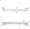
- FIG. 1 is a perspective view showing an indoor unit of an air conditioner according to an embodiment of the present disclosure.
- FIG. 2 is a sectional view of FIG. 1 .
- FIG. 3 is an exploded perspective view showing a front panel of FIG. 1 .
- FIG. 4 is an exploded perspective view showing the upper part of the front panel of FIG. 1 .
- FIG. 5 is a perspective view of a vane module shown in FIG. 3 .
- FIG. 6 is a perspective view of FIG. 5 when viewed in another direction.
- FIG. 7 is a perspective view of the vane module of FIG. 5 when viewed from above.
- FIG. 8 is a front view of the vane module shown in FIG. 3 .
- FIG. 9 is a rear view of the vane module shown in FIG. 3 .
- FIG. 1 is a perspective view showing an indoor unit of an air conditioner according to an embodiment of the present disclosure.
- FIG. 2 is a sectional view of FIG. 1 .
- FIG. 3 is an
- FIG. 10 is a plan view of the vane module shown in FIG. 3 .
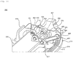
- FIG. 11 is a perspective view showing the operation structure of the vane module shown in FIG. 5 .
- FIG. 12 is a front view of a driving link shown in FIG. 11 .
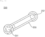
- FIG. 13 is a front view of a first vane link shown in FIG. 11 .
- FIG. 14 is a front view of a second vane link shown in FIG. 11 .
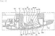
- FIG. 15 is a side sectional view of the vane module shown in FIG. 2 .
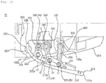
- FIG. 16 is an illustrative view of discharge step P1 according to a first embodiment of the present disclosure.
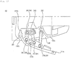
- FIG. 17 is an illustrative view of discharge step P2 according to a first embodiment of the present disclosure.
- FIG. 18 is an illustrative view of discharge step P3 according to a first embodiment of the present disclosure.
- FIG. 19 is an illustrative view of discharge step P4 according to a first embodiment of the present disclosure.
- FIG. 20 is an illustrative view of discharge step P5 according to a first embodiment of the present disclosure.
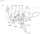
- FIG. 21 is an illustrative view of discharge step P6 according to a first embodiment of the present disclosure.
- FIG. 22 is an enlarged view of a second vane and a discharge guide shown in FIG. 16 .
- FIG. 23 is a graph showing the flow of air in a discharge port according to a first embodiment of the present disclosure.
- the indoor unit of the air conditioner includes a case 100 having a suction port 101 and a discharge port 102, an indoor heat exchanger 130 disposed in the case 100, and an indoor blowing fan 140 disposed in the case 100 to blow air to the suction port 101 and the discharge port 102.
- the case 100 includes a case housing 110 and a front panel 300.
- the case housing 110 is installed at the ceiling of a room via a hanger (not shown) so as to be suspended therefrom, and the lower side of the case housing is open.
- the front panel 300 covers the open surface of the case housing 110, is disposed so as to face the floor of the room, is exposed in the room, and has the suction port 101 and the discharge port 102.
- the case 100 may be variously realized depending on the form of manufacture, and construction of the case 100 does not limit the idea of the present disclosure.
- the suction port 101 is disposed in the center of the front panel 300, and the discharge port 102 is disposed outside the suction port 101.
- the number of suction ports 101 or the number of discharge ports 102 is irrelevant to idea of the present disclosure.
- a single suction port 101 is formed, and a plurality of discharge ports 102 is disposed.
- the suction port 101 is formed so as to have a quadrangular shape when viewed from below, and four discharge ports 102 are disposed so as to be spaced apart from edges of the suction port 101 by a predetermined distance.
- the indoor heat exchanger 130 is disposed between the suction port 101 and the discharge port 102, and the indoor heat exchanger 130 partitions the interior of the case 100 into an inner interior and an outer interior. In this embodiment, the indoor heat exchanger 130 is disposed vertically.
- the indoor blowing fan 140 is located inside the indoor heat exchanger 130.
- the indoor heat exchanger When viewed in a top view or a bottom view, the indoor heat exchanger has an overall shape of " ⁇ ", a portion of which may be separated.
- the indoor heat exchanger 130 is disposed such that air discharged from the indoor blowing fan 140 perpendicularly enters the indoor heat exchanger.
- a drain pan 132 is installed in the case 100, and the indoor heat exchanger 130 is held by the drain pan 132. Condensate water generated in the indoor heat exchanger 130 may flow to the drain pan 132 and then be stored.
- a drain pump (not shown) configured to discharge collected condensate water to the outside is disposed in the drain pan 132.
- the drain pan 132 may be provided with an inclined surface having directivity in order to collect and store condensate water falling from the indoor heat exchanger 130 in one side.
- the indoor blowing fan 140 is located in the case 100, and is disposed at the upper side of the suction port 101.
- a centrifugal blower configured to suction air to the center thereof and discharging the air in the circumferential direction is used as the indoor blowing fan 140.
- the indoor blowing fan 140 includes a bell mouth 142, a fan 144, and a fan motor 146.
- the bell mouth 142 is disposed at the upper side of a suction grill 320, and is located at the lower side of the fan 144.
- the bell mouth 142 guides air that has passed through the suction grill 320 to the fan 144.
- the fan motor 146 rotates the fan 144.
- the fan motor 146 is fixed to the case housing 110.
- the fan motor 146 is disposed at the upper side of the fan 144. At least a portion of the fan motor 146 is located higher than the fan 144.
- a motor shaft of the fan motor 146 is disposed so as to face downwards, and the fan 144 is coupled to the motor shaft.
- the indoor heat exchanger 130 is located outside the edge of the fan 144.
- the fan 144 and at least a portion of the indoor heat exchanger 130 are disposed on the same horizontal line.
- At least a portion of the bell mouth 142 is inserted into the fan 144. In the upward-downward direction, at least a portion of the bell mouth 142 overlaps the fan 144.
- the indoor heat exchanger 130 is disposed in the case hosing 110, and partitions the space in the case housing 110 into an inner space and an outer space.
- the inner space surrounded by the indoor heat exchanger 130 is defined as a suction channel 103, and the outer space outside the indoor heat exchanger 130 is defined as a discharge channel 104.
- the indoor blowing fan 140 is disposed in the suction channel 103.
- the discharge channel 104 is located between the outside of the indoor heat exchanger 130 and the sidewall of the case housing 110.
- the suction channel 103 When viewed in a top view or a bottom view, the suction channel 103 is an inside surrounded by " ⁇ " of the indoor heat exchanger, and the discharge channel 104 is an outside of " ⁇ " of the indoor heat exchanger.
- the suction channel 103 communicates with the suction port 101, and the discharge channel 104 communicates with the discharge port 103 .
- Air flows from the lower side to the upper side of the suction channel 103, and flows from the upper side to the lower side of the discharge channel 104.
- the flow direction of air is changed 180 degrees based on the indoor heat exchanger 130.
- the suction port 101 and the discharge port 102 are formed in the same surface of the front panel 300.
- the suction port 101 and the discharge port 102 are disposed so as to face in the same direction.
- the suction port 101 and the discharge port 102 are disposed so as to face the floor of the room.
- the discharge port 102 may be formed so as to have a slight side inclination; however, the discharge port 102 connected to the discharge channel 104 is formed so as to face downwards.
- a vane module 200 is disposed to control the direction of air that is discharged through the discharge port 102.
- the front panel 300 includes a front body 310 coupled to the case housing 110, the front body having the suction port 101 and the discharge port 102, a suction grill 320 having a plurality of grill holes 321, the suction grill being configured to cover the suction port 101, a pre-filter 330 separably assembled to the suction grill 320, and a vane module 200 installed at the front body 310, the vane module being configured to control the air flow direction of the discharge port 102.
- the suction grill 320 is installed so as to be separable from the front body 310.
- the suction grill 320 may be elevated from the front body 310 in the upward-downward direction.
- the suction grill 320 covers the entirety of the suction port 101.
- the suction grill 320 has a plurality of grill holes 321 formed in the shape of a lattice.
- the grill holes 321 communicate with the suction port 101.
- the pre-filter 330 is disposed at the upper side of the suction grill 320.
- the pre-filter 330 filters air suctioned into the case 100.
- the pre-filter 330 is located at the upper side of grill holes 321, and filters air that has passed through the suction grill 320.
- the discharge port 102 is formed along the edge of the suction port 101 in the form of a long slit.
- the vane module 200 is located on the discharge port 102, and is coupled to the front body 310.
- the vane module 200 may be separated downwards from the front body 310. That is, the vane module 200 may be disposed irrespective of the coupling structure of the front body 310, and may be separated independently from the front body 310. The structure thereof will be described in more detail.
- the front body 310 is coupled to the lower side of the case housing 110, and is disposed so as to face the room.
- the front body 310 is installed at the ceiling of the room, and is exposed in the room.
- the front body 310 is coupled to the case housing 110, and the case housing 110 supports load of the front body 310.
- the front body 310 supports load of the suction grill 320 and the pre-filter 330.
- the front body 310 When viewed in a top view, the front body 310 is formed so as to have a quadrangular shape. The shape of the front body 310 may be varied.
- the upper surface of the front body 310 may be formed horizontally so as to be in tight contact with the ceiling, and the edge of the lower surface of the front body may be slightly curved.
- a suction port 101 is disposed in the center of the front body 310, and a plurality of discharge ports 102 is disposed outside the edge of the suction port 101.
- the suction port 101 When viewed in a top view, the suction port 101 may be formed in a square shape, and each discharge port 102 may be formed in a rectangular shape.
- the discharge port 102 may be formed in a slit shape having a greater length than the width thereof.
- the front body 310 includes a front frame 312, a side cover 314, and a corner cover 316.
- the front frame 312 provides load and stiffness of the front panel 300, and is fixed to the case housing 110 by fastening.
- the suction port 101 and the four discharge ports 102 are formed in the front frame 312.
- the front frame 312 includes a side frame 311 and a corner frame 313.
- the corner frame 313 is disposed at each corner of the front panel 300.
- the side frame 311 is coupled to two corner frames 313.
- the side frame 311 includes an inner side frame 311a and an outer side frame 311b.
- the inner side frame 311a is disposed between the suction port 101 and the discharge port 102, and couples two corner frames 313 to each other.
- the outer side frame 311b is disposed outside the discharge port 102.
- four inner side frames 311a and four outer side frames 311b are provided.
- the suction port 101 is located inside the four inner side frames 311a.
- the discharge port 102 is formed so as to be surrounded by two corner frames 313, the inner side frame 311a, and the outer side frame 311b.
- the side cover 314 and the corner cover 316 are coupled to the lower surface of the front frame 312.
- the side cover 314 and the corner cover 316 are exposed to a user, and the front frame 312 is not visible to the user.
- the side cover 314 is disposed at the edge of the front frame 312, and the corner cover 316 is disposed at the corner of the front frame 312.
- the side cover 314 is made of a synthetic resin material, and is fixed to the front frame 312 by fastening. Specifically, the side cover 314 is coupled to the side frame 311, and the corner cover 316 is coupled to the corner frame 313.
- four side covers 314 and four corner covers 316 are provided.
- the side covers 314 and the corner covers 316 are coupled to the front frame 312 to form a single structure.
- the four side covers 314 and the four corner covers 316 form a single edge of the front panel 300.
- the side cover 314 is disposed at the lower side of the side frame 311, and the corner cover 316 is disposed at the lower side of the corner frame 313.
- the four side covers 314 and the four corner covers 316 are assembled to form a quadrangular frame.
- the four side covers 314 and the four corner covers 316 connected to each other are defined as a front decoration 350.
- the front decoration 350 has a decoration outer border 351 and a decoration inner border 352.
- the decoration outer border 351 is formed in a quadrangular shape, and the decoration inner border 352 is generally formed in a quadrangular shape.
- the corner of the decoration inner border has predetermined curvature.
- the suction grill 320 and four vane modules 200 are disposed inside the decoration inner border 352.
- the suction grill 320 and four vane modules 200 abut the decoration inner border 352.
- each side cover 314 is coupled to the front frame 312.
- the outer edge of the side cover 314 defines a portion of the decoration outer border 351, and the inner edge of the side cover 314 defines a portion of the decoration inner border 352.
- the inner edge of the side cover 314 defines the outer border of the discharge port 102.
- the inner edge of the side cover 314 is defined as a side decoration inner border 315.
- each corner cover 316 is coupled to the front frame 312.
- the outer edge of the corner cover 316 defines a portion of the decoration outer border 351, and the inner edge of the corner cover 316 defines a portion of the decoration inner border 352.
- the inner edge of the corner cover 316 is defined as a corner decoration inner border 317.
- the corner decoration inner border 317 may be disposed so as to contact the suction grill 320.
- the inner edge of the corner cover 316 is disposed so as to face the suction grill 320, and is spaced apart therefrom by a predetermined distance to form a gap 317a.
- the side decoration inner border 315 is also spaced apart from the vane module 200 to form a gap 315a, and is disposed so as to face the outer edge of the vane module 200.
- the decoration inner border 352 is spaced apart from the outer edges of the four vane modules 200 and the suction grill 320 to form a continuous gap.
- a continuous gap defined by four side decoration inner border gaps 315a and four corner decoration inner border gaps 317a is defined as a front decoration gap 350a.
- the front decoration gap 350a is formed at the inner edge of the front decoration 350. Specifically, the front decoration gap 350a is formed as the result of the outer edges of the vane module 200 and the suction grill 320 and the inner edge of the front decoration 350 being spaced apart from each other.
- the front decoration gap 350a allows the suction grill 320 and the vane module 200 to be seen as a single structure.
- the suction grill 320 is located at the lower side of the front body 310.
- the suction grill 320 may be moved downwards in the state of being in tight contact with the lower surface of the front body 310.
- the suction grill 320 includes a grill body 322 and a plurality of grill holes 321 formed through the grill body 322 in the upward-downward direction.
- the suction grill 320 includes a grill body 322 disposed at the lower side of the suction port 101, the grill body communicating with the suction port 101 through a plurality of grill holes 321, the grill body being formed in a quadrangular shape, and a grill corner portion 327 formed at the corners of the grill body 322 so as to extend in the diagonal direction.
- the lower surface of the grill body 322 and the lower surface of a first vane 210 may define a continuous surface.
- the lower surface of the grill body 322 and the lower surface of the corner cover 316 may define a continuous surface.
- a plurality of grills 323 is disposed inside the grill body 322 in the shape of a lattice.
- the lattice-shaped grills 323 define quadrangular grill holes 321.
- the portion at which the grills 323 and the grill holes 321 are formed is defined as a suction portion.
- the grill body 322 includes a suction portion configured to communicate with air and a grill body portion 324 disposed so as to surround the suction portion.
- the suction portion When viewed in a top view or a bottom view, the suction portion is generally formed in a quadrangular shape.
- Each corner of the suction portion is disposed so as to face a corresponding corner of the front panel 300, and more specifically is disposed so as to face the corner cover 316.
- the grill body 322 When viewed in a bottom view, the grill body 322 is formed in a quadrangular shape.
- the outer edge of the grill body portion 324 is disposed so as to face the discharge port 102 or the front decoration 350.
- the outer edge of the grill body portion 324 includes a grill corner border 326 disposed so as to face the corner cover 316 and a grill side border 325 defining the discharge port 102, the grill side border being disposed so as to face the side cover 314.
- the grill corner border 326 may have curvature formed about the inside of the suction grill 320, and the grill side border 325 may have curvature formed about the outside of the suction grill 320,
- the grill body portion 324 further includes a grill corner portion 327 surrounded by the grill corner border 326 and two grill side borders 325.
- the grill corner portion 327 is formed at the grill body portion 324 so as to protrude toward the corner cover 316.
- the grill corner portion 327 is disposed at each corner of the grill body 322.
- the grill corner portion 327 extends toward each corner of the front panel 300.
- the four grill corner portions 327 are disposed.
- the four grill corner portions 327 are defined as a first grill corner portion 327-1, a second grill corner portion 327-2, a third grill corner portion 327-3, and a fourth grill corner portion 327-4.
- the grill side border 325 is formed so as to be concave from the outside to the inside.
- the discharge port 102 is formed between the side cover 314 and the suction grill 320. More specifically, one discharge port 102 is formed between the side decoration inner border 315 of the side cover 314 and the grill side border 325 of the grill body 322. Discharge ports 102 are formed between side decoration inner borders 315 and grill side borders 325 disposed in four directions of the suction grill 320.
- the length of the grill corner border 326 is equal to the length of the corner decoration inner border 317. That is, the width of the corner cover 316 is equal to the width of the grill corner portion 327.
- the width of the inside of the side cover 314 is equal to the width of the grill side border 325.
- the grill side border 325 will be described in more detail.
- the grill side border 325 defines the inner border of the discharge port 102.
- the side decoration inner border 315 and the corner decoration inner border 317 define the outer border of the discharge port 102.
- the grill side border 325 includes a long straight section 325a extending long in the longitudinal direction of the discharge port 102, the long straight section being formed in a straight line, a first curved section 325b connected to one side of the long straight section 325a, the first curved section having the center of curvature outside the suction grill 320, a second curved section 325c connected to the other side of the long straight section 325a, the first curved section having the center of curvature outside the suction grill 320, a first short straight section 325d connected to the first curved section, and a second short straight section 325e connected to the second curved section 325c.
- the vane module 200 is installed in the discharge channel 104, and controls the flow direction of air that is discharged through the discharge port 102.
- the vane module 200 includes a module body 400, a first vane 210, a second vane 220, a vane motor 230, a driving link 240, a first vane link 250, and a second vane link 260.
- the first vane 210, the second vane 220, the vane motor 230, the driving link 240, the first vane link 250, and the second vane link 260 are all installed at the module body 400.
- the module body 400 is installed integrally at the front panel 300. That is, all of the components of the vane module 200 are modularized and are installed at the front panel 300 at once.
- vane module 200 Since the vane module 200 is modularized, it is possible to reduce assembly time and to achieve easy replacement at the time of trouble.
- a stepper motor is used as the vane motor 230.
- the module body 400 may be constituted by a single body.
- the module body is manufactured using two separate parts in order to minimize installation space and to minimize manufacturing cost.
- the module body 400 includes a first module body 410 and a second module body 420.
- the first module body 410 and the second module body 420 are formed in horizontal symmetry.
- the first module body 410 is described by way of example.
- Each of the first module body 410 and the second module body 420 is fastened to the front body 310. Specifically, each of the first module body 410 and the second module body 420 is installed at the corner frame 313.
- the first module body 410 is installed at the corner frame 313 disposed at one side of the discharge port 102
- the second module body 420 is installed at the corner frame 313 disposed at the other side of the discharge port 102.
- each of the first module body 410 and the second module body 420 is in tight contact with the lower surface of the corner frame 313, and is fastened thereto via a fastening member 401.
- the first module body 410 and the second module body 420 are disposed at the lower side of the front body 310.
- the direction in which the first module body 410 and the corner frame 313 are fastened to each other is disposed so as to be directed from the lower side to the upper side
- the direction in which the second module body 420 and the corner frame 313 are fastened to each other is also disposed so as to be directed from the lower side to the upper side.
- the entirety of the vane module 200 may be easily separated from the front body 310 during repair.
- the vane module 200 includes a first module body 410 disposed at one side of the discharge port 102, the first module body being located at the lower side of the front body 310, the first module body being assembled to the front body 310 so as to be separable downwards therefrom, a second module body 420 disposed at the other side of the discharge port 102, the second module body being located at the lower side of the front body 310, the second module body being assembled to the front body 310 so as to be separable downwards therefrom, at least one vane 210 and 220 having one side and the other side coupled to the first module body 410 and the second module body 420, respectively, the vane being configured to be rotated relative to the first module body 410 and the second module body 420, a vane motor 230 installed at at least one of the first module body 410 or the second module body 420, the vane motor being configured to provide driving force to the vane, a first fastening hole 403-1 disposed at the first module body 410, the first fastening
- first module body 410 and the second module body 420 are located at the lower side of the front body 310, only the main module 200 may be separated from the front body 310 in the state in which the front body 310 is installed at the case housing 110. This is commonly applied to all of the four vane modules 200.
- the entirety of the vane module 200 is separated downwards from the front body 310.
- the first module body 410 includes a module body portion 402 coupled to the front body 310 and a link installation portion 404 protruding upwards from the module body portion 402.
- the module body portion 402 is securely fastened to the front body 310 in order to minimize generation of vibration or noise due to the first vane 210, the second vane 220, the vane motor 230, the driving link 240, the first vane link 250, and the second vane link 260.
- the fastening member 401 provided to fix the module body portion 402 is in the state of being fastened from the lower side to the upper side, and may be separated from the upper side to the lower side.
- the fastening hole formed in the first module body 410 is referred to as a first fastening hole 403-1
- the fastening hole formed in the second module body 420 is referred to as a second fastening hole 403-1 .
- the fastening member 401 installed in the first fastening hole 403-1 is defined as a first fastening member 401-1
- the fastening member 401 installed in the second fastening hole 403-1 is defined as a second fastening member 401-2.
- the first fastening member 401-1 is fastened to the front body 310 through the first fastening hole.
- the second fastening member 401-2 is fastened to the front body 310 through the second fastening hole.
- a module hook 405 configured to temporarily fix the position of the module body 400 is disposed.
- the module hook 405 is coupled to the front panel 300, specifically the front body 310. Specifically, the module hook 405 and the front body 310 are caught by each other.
- a plurality of module hooks 405 may be disposed at one module body.
- module hooks are disposed at the outer edge and the front edge of the module body portion 402. That is, module hooks 405 are disposed outside the first module body 410 and the second module body 420, and the module hooks 405 are symmetrical with each other in the leftward-rightward direction.
- the vane module 200 may be temporarily fixed to the frame body 310 by the module hook 405 of the first module body 410 and the module hook 405 of the second module body 420.
- the fastening member 401 securely fixes the temporarily fixed module body 400 to the front body 310.
- the fastening hole 403, in which the fastening member 401 is installed, may be located between the module hooks 405.
- the fastening hole 403 of the first module body 410 and the fastening hole 403 of the second module body 420 are disposed between one module hook 405 and the other module hook 405.
- the module hooks 405 and the fastening holes 403 are disposed in a line.
- vane module 200 is primarily fixed by the module hook 405 and is secondary fixed by the fastening member 401, it is possible to greatly improve work convenience at the time of repair.
- the module body portion 402 is disposed horizontally, and the link installation portion 404 is disposed vertically. In particular, the link installation portion 404 protrudes upwards from the module body portion 402 in the state of being installed.
- the link installation portion 404 of the first module body 410 and the link installation portion 404 of the second module body 420 are disposed so as to face each other.
- the first vane 210, the second vane 220, the driving link 240, the first vane link 250, and the second vane link 260 are installed between the link installation portion 404 of the first module body 410 and the link installation portion 404 of the second module body 420.
- the vane motor 230 is disposed outside the link installation portion 404 of the first module body 410 or the link installation portion 404 of the second module body 420.
- the vane motor 230 may be installed at only one of the first module body 410 and the second module body 420. In this embodiment, the vane motor 230 may be installed at each of the first module body 410 and the second module body 420.
- the first vane 210, the second vane 220, the driving link 240, the first vane link 250, and the second vane link 260 are coupled between the first module body 410 and the second module body 420, whereby the vane module 200 is integrated.
- a vane motor installation portion 406 protruding outside the link installation portion 404 is disposed.
- the vane motor 230 is fixed to the vane motor installation portion 406 by fastening.
- the vane motor installation portion 406 is formed in the shape of a boss, and the vane motor 230 is fixed to the vane motor installation portion 406.
- a driving link coupling portion 407 to which the driving link 240 is assembled and which provides the center of rotation to the driving link 240, a first vane link coupling portion 408 to which the first vane link 250 is assembled and which provides the center of rotation to the first vane link 250, and a second vane coupling portion 409 which is coupled with the second vane 220 and which provides the center of rotation to the second vane 220 are disposed at the link installation portion 404.
- each of the driving link coupling portion 407, the first vane link coupling portion 408, and the second vane coupling portion 409 is formed in the shape of a hole. Unlike this embodiment, the same may be formed in the shape of a boss, or may be realized as any of various forms that provide a rotary shaft.
- a stopper 270 configured to limit the rotational angle of the driving link 240 is disposed at the link installation portion 404.
- the stopper 270 is disposed so as to protrude toward the opposite link installation portion 404.
- the stopper 270 interferes with the driving link 240 at a specific position at the time of rotation thereof, and limits rotation of the driving link 240.
- the stopper 270 is located within the radius of rotation of the driving link 240.
- the stopper 270 is manufactured integrally with the link installation portion 404. In this embodiment, the stopper 270 defines the installation position of the driving link 240, remains in contact with the driving link 240 at the time of rotation thereof, and inhibits vibration or free movement of the driving link 240.
- the stopper 270 is formed in the shape of an arc.
- the driving link 240 is directly connected to the vane motor 230.
- a motor shaft (not shown) of the vane motor 230 is directly coupled to the driving link 240, and the rotation amount of the driving link 240 is determined based on the rotational angle of the rotary shaft of the vane motor 230.
- the driving link 240 is assembled to the vane motor 230 through the link installation portion 404.
- the driving link 240 extends through the driving link coupling portion 407.
- the driving link 240 includes a driving link body 245, a first driving link shaft 241 disposed at the driving link body 245, the first driving link shaft being rotatably coupled to the first vane 210, a core link shaft 243 disposed at the driving link body 245, the core link shaft being rotatably coupled to the link installation portion 404 (specifically, the driving link coupling portion 407), and a second driving link shaft 242 disposed at the driving link body 245, the second driving link shaft being rotatably coupled to the second vane link 260.
- the driving link body 245 includes a first driving link body 246, a second driving link body 247, and a core body 248.
- the core link shaft 243 is disposed at the core body 248, the first driving link shaft 241 is disposed at the first driving link body 246, and the core link shaft 243 is disposed at the second driving link body 247.
- the core body 248 connects the first driving link body 246 and the second driving link body 247 to each other.
- the shape of each of the first driving link body 246 and the second driving link body 247 is not particularly restricted. In this embodiment, however, each of the first driving link body 246 and the second driving link body 247 is generally formed in the shape of a straight line.
- the first driving link body 246 is longer than the second driving link body 247.
- the core link shaft 243 is rotatably assembled to the link installation portion 404.
- the core link shaft 243 is assembled to the driving link coupling portion 407 formed at the link installation portion 404.
- the core link shaft 243 may be rotated relative to the driving link coupling portion 407 in the state of being coupled thereto.
- the first driving link shaft 241 is rotatably assembled to the first vane 210.
- the second driving link shaft 242 is rotatably assembled to the second vane link 260.
- the first driving link shaft 241 and the second driving link shaft 242 protrude in the same direction.
- the core link shaft 243 protrudes in the direction opposite the first driving link shaft 241 and the second driving link shaft 242.
- the first driving link body 246 and the second driving link body 247 have a predetermined angle therebetween.
- An imaginary straight line joining the first driving link shaft 241 and the core link shaft 243 to each other and an imaginary straight line joining the core link shaft 243 and the second driving link shaft 242 to each other have a predetermined angle E therebetween.
- the angle E is greater than 0 degrees and less than 180 degrees.
- the first driving link shaft 241 has a structure in which the driving link body 245 and the first vane 210 can be rotated relative thereto.
- the first driving link shaft 241 is formed integrally with the driving link body 245.
- the first driving link shaft 241 may be manufactured integrally with the first vane 210 or the joint rib 214.
- the core link shaft 243 has a structure in which the driving link body 245 and the module body (specifically, the link installation portion 404) can be rotated relative thereto.
- the core link shaft 243 is formed integrally with the driving link body 245.
- the second driving link shaft 242 has a structure in which the second vane link 260 and the driving link 240 can be rotated relative thereto.
- the second driving link shaft 242 is formed integrally with the driving link body 245.
- the second driving link shaft 242 may be manufactured integrally with the second vane link 260.
- the second driving link shaft 242 is disposed at the second driving link body 247.
- the second driving link shaft 242 is disposed opposite the first driving link shaft 241 on the basis of the core link shaft 243.
- An imaginary straight line joining the first driving link shaft 241 and the core link shaft 243 to each other and an imaginary straight line joining the core link shaft 243 and the second driving link shaft 242 to each other have a predetermined angle E therebetween.
- the angle E is greater than 0 degrees and less than 180 degrees.
- the first vane link 250 is made of a strong material, and is formed in the shape of a straight line. Unlike this embodiment, the first vane link 250 may be curved.
- the first vane link 250 includes a first vane link body 255, a 1-1 vane link shaft 251 disposed at the first vane link body 255, the 1-1 vane link shaft being assembled to the first vane 210, the 1-1 vane link shaft being configured to be rotated relative to the first vane 210, and a 1-2 vane link shaft 252 disposed at the first vane link body 255, the 1-2 vane link shaft being assembled to the module body 400 (specifically, the link installation portion 404), the 1-2 vane link shaft being configured to be rotated relative to the module body 400.
- the 1-1 vane link shaft 251 protrudes toward the first vane 210.
- the 1-1 vane link shaft 251 may be assembled to the first vane 210, and may be rotated relative to the first vane 210.
- the 1-2 vane link shaft 252 is assembled to the link installation portion 404 of the module body 400. Specifically, the 1-2 vane link shaft 252 may be assembled to the first vane link coupling portion 408, and may be rotated relative to the first vane link coupling portion 408.
- the second vane link 260 is made of a strong material, and is formed in the shape of a straight line. Unlike this embodiment, the first vane link 250 may be curved.
- the second vane link 260 includes a second vane link body 265, a 2-1 vane link shaft 261 disposed at the second vane link body 265, the 2-1 vane link shaft being assembled to the second vane 220, the 2-1 vane link shaft being configured to be rotated relative to the second vane 220, and a 2-2 vane link journal 262 disposed at the second vane link body 265, the 2-2 vane link journal being assembled to the driving link 240 (specifically, the second driving link shaft 242), the 2-2 vane link journal being configured to be rotated relative to the driving link 240.
- the 2-2 vane link journal 262 is formed in the shape of a hole formed through the second vane link body 265. Since the 2-2 vane link journal 262 and the second driving link shaft 242 have relative structures, one is formed in the shape of a shaft and the other is formed in the shape of a hole having the center of rotation. Unlike this embodiment, therefore, the 2-2 vane link journal 262 may be formed in the shape of a shaft, and the second driving link shaft may be formed in the shape of a hole.
- the direction in which air is discharged is defined as the front, and the direction opposite thereto is defined as the rear.
- the ceiling side is defined as the upper side, and the floor is defined as the lower side.
- first vane 210 and the second vane 220 are disposed in order to control the flow direction of air that is discharged from the discharge port 102.
- the relative disposition and relative angle between the first vane 210 and the second vane 220 are changed according to steps of the vane motor 230.
- the first vane 210 and the second vane 220 provide six discharge steps P1, P2, P3, P4, P5, and P6 in pairs according to steps of the vane motor 230.
- the discharge steps P1, P2, P3, P4, P5, and P6 are defined as states in which the first vane 210 and the second vane 220 are stationary, rather than moved.
- moving steps may be provided.
- the moving steps result from a combination of the six discharge steps P1, P2, P3, P4, P5, and P6, and are defined as the current of air provided by the operation of the first vane 210 and the second vane 220.
- the first vane 210 is disposed between the link installation portion 404 of the first module body 410 and the link installation portion 404 of the second module body 420.
- the first vane 210 covers most of the discharge port 210. Unlike this embodiment, the first vane 210 may be manufactured so as to cover the entirety of the discharge port 210.
- the first vane 210 is coupled to the driving link 240 and the first vane link 250.
- the driving link 240 and the first vane link 250 are disposed at one side and the other side of the first vane 210, respectively.
- the first vane 210 is rotated relative to the driving link 240 and the first vane link 250.
- the driving link 240 coupled to the first module body 410 is defined as a first driving link
- the first vane link 250 coupled to the first module body 410 is defined as a 1-1 vane link
- the driving link 240 coupled to the second module body 420 is defined as a second driving link
- the first vane link 250 coupled to the second module body 420 is defined as a 1-2 vane link.
- the first vane 210 includes a first vane body 212 formed so as to extend long in the longitudinal direction of the discharge port 102 and a joint rib 214 protruding upwards from the first vane body 212, the driving link 240 and the first vane link 250 being coupled to the joint rib.
- the first vane body 212 may be formed so as to have a gently curved surface.
- the first vane body 212 controls the direction of air that is discharged along the discharge channel 104.
- the discharged air collides with the upper surface or the lower surface of the first vane body 212, whereby the flow direction thereof may be guided.
- the flow direction of the discharged air and the longitudinal direction of the first vane body 212 are perpendicular to each other or intersect each other.
- the joint rib 214 is an installation structure for coupling between the driving link 240 and the first vane link 250.
- the joint rib 214 is disposed at each of one side and the other side of the first vane 210.
- the joint rib 214 is formed so as to protrude upwards from the upper surface of the first vane body 212.
- the joint rib 214 is formed in the flow direction of discharged air, and minimizes resistance to the discharged air. Consequently, the joint rib 214 is perpendicular to or intersects the longitudinal direction of the first vane body 212.
- the joint rib 214 is formed such that the air discharge side (the front) of the joint rib is low and the air entrance side (the rear) of the joint rib is high.
- the joint rib 214 is formed such that the side of the joint rib to which the driving link 240 is coupled is high and the side of the joint rib to which the first vane link 250 is coupled is low.
- the joint rib 214 has a second joint portion 217 rotatably coupled with the driving link 240 and a first joint portion 216 rotatably coupled with the first vane link 250.
- the joint rib 214 may be manufactured integrally with the first vane body 212.
- each of the first joint portion 216 and the second joint portion 217 is formed in the shape of a hole, and is formed through the joint rib 214.
- Each of the first joint portion 216 and the second joint portion 217 is a structure in which axial coupling or hinge coupling is possible, and may be changed into any of various forms.
- the second joint portion 217 When viewed from the front, the second joint portion 217 is located higher than the first joint portion 216.
- the second joint portion 217 is located further rearwards than the first joint portion 216.
- the first driving link shaft 241 is assembled to the second joint portion 217.
- the second joint portion 217 and the first driving link shaft 241 are assembled so as to be rotatable relative to each other.
- the first driving link shaft 241 is assembled through the second joint portion 217.
- the 1-1 vane link shaft 251 is assembled to the first joint portion 216.
- the first joint portion 216 and the 1-1 vane link shaft 251 are assembled so as to be rotatable relative to each other.
- the 1-1 vane link shaft 251 is assembled through the first joint portion 216.
- the driving link 250 and the first vane link 250 are disposed between the joint rib 214 and the link installation portion 404.
- the distance between the first joint portion 216 and the second joint portion 217 is less than the distance between the core link shaft 243 and the 1-2 vane link shaft 252.
- the second vane 220 includes a second vane body 222 formed so as to extend long in the longitudinal direction of the discharge port 102, a joint rib 224 protruding upwards from the second vane body 222, the joint rib 224 being coupled to the second vane link 260 so as to be rotatable relative thereto, and a second vane shaft 221 formed at the second vane body 222, the second vane shaft being rotatably coupled to the link installation portion 404.
- the joint rib 224 is a structure in which axial coupling or hinge coupling is possible, and may be changed into any of various forms.
- a hole formed in the second joint rib 224 and coupled to the second vane link 220 so as to be rotatable relative thereto is defined as a third joint portion 226.
- the third joint portion 226 is formed in the shape of a hole, and is formed through the joint rib 224.
- the third joint portion 226 is a structure in which axial coupling or hinge coupling is possible, and may be changed into any of various forms.
- the joint rib of the first vane is defined as a first joint rib 214
- the joint rib of the second vane is defined as a second joint rib 224.
- the second vane 220 may be rotated about the second joint rib 224, and may also be rotated about the second vane shaft 221. That is, the second vane 220 may be rotated relative to each of the second joint rib 224 and the second vane shaft 221.
- the second joint rib 224 When viewed in a top view, the second joint rib 224 is located further forwards than the second vane shaft 221. The second joint rib 224 is moved along a predetermined orbit about the second vane shaft 221.
- the second vane body 222 may be formed so as to be gently curved.
- the second vane body 222 controls the direction of air that is discharged along the discharge channel 104.
- the discharged air collides with the upper surface or the lower surface of the second vane body 222, whereby the flow direction thereof is guided.
- the flow direction of the discharged air and the longitudinal direction of the second vane body 222 are perpendicular to each other or intersect each other.
- the second vane body 222 When viewed in a top view, at least a portion of the second vane body 222 may be located between the first joint portions 212 of the first vane 210.
- the front end of the second vane body 222 is located between the first joint portions 214. That is, the front length of the second vane body 222 is less than the length between the first joint portions 214.
- the second joint rib 224 is an installation structure for assembly with the second vane link 260.
- the second joint rib 224 is disposed at each of one side and the other side of the second vane body 222.
- the second joint rib 224 is coupled to the second vane link 260 so as to be rotatable relative thereto.
- the third joint point 226 and the second vane link 260 are axially coupled to each other so as to be rotatable relative to each other.
- the second joint rib 224 is formed so as to protrude upwards from the upper surface of the second vane body 222.
- the second joint rib 224 is preferably formed in the flow direction of discharged air. Consequently, the second joint rib 224 is disposed so as to perpendicular to or intersect the longitudinal direction of the second vane body 222.
- the second vane 220 is rotated about the second vane shaft 221.
- the second vane shaft 221 is formed at each of one side and the other side of the second vane body 222.
- One second vane shaft 221 protrudes toward the link installation portion 404 disposed at one side, and the other second vane shaft 221 protrudes toward the link installation portion 404 disposed at the other side.
- the second vane coupling portion 411 rotatably coupled to the second vane shaft 221 is disposed at the module body 400.
- the second vane coupling portion 411 is formed in the shape of a hole formed through the module body 400.
- the second vane shaft 221 is located further rearwards than the second joint rib 224.
- the second vane link 260, the driving link 240, and the first vane line 250 are sequentially disposed in front of the second vane shaft 221.
- driving link coupling portion 407 and the first vane link coupling portion 408 are sequentially disposed in front of the second vane coupling portion 411 .
- the suction grill 320 When the suction grill 320 is separated in the state of FIG. 1 , four vane modules 200 are exposed, as shown in FIG. 15 .
- the suction grill 320 is separably assembled to the front body 310.
- the suction grill 320 may be separated from the front body 310 using various methods.
- the suction grill 320 may be separated using a method of separating and rotating one edge of the suction grill on the basis of the other edge of the suction grill. In another method, the suction grill 320 may be separated from the front body 310 through release of catching in the state of being caught by the front body. In a further method, coupling between the suction grill 200 and the front body 310 may be maintained by magnetic force.
- the suction grill 320 may be moved in the upward-downward direction by an elevator 500 installed at the front body 310.
- the elevator 500 is connected to the suction grill 320 via a wire (not shown).
- the wire may be wound or unwound by operation of the elevator 500, whereby the suction grill 320 may be moved downwards or upwards.
- a plurality of elevators 500 is disposed, and the elevators 500 simultaneously move opposite sides of the suction grill 320.
- At least one of the first vane 210 or the second vane 220 of the vane module 200 may be exposed.
- the indoor unit When the indoor unit is not operated, only the first vane 210 is exposed to the user. When the indoor unit is operated and air is discharged, the second vane 220 may be selectively exposed to the user.
- the fastening holes 403 are disposed at the first module body 410 and the second module body 420, the fastening holes 403 are hidden by the suction grill 320 so as not to be visible to the user.
- the grill corner portion 327 prevents the first module body 410 and the second module body 420 from being exposed outside.
- the grill corner portion 327 also prevents the fastening holes 403 formed in the first module body 410 and the second module body 420 from being exposed outside. Since the grill corner portion 327 is located at the lower side of the fastening holes 403, the fastening holes 403 are hidden by the grill corner portion 327.
- the suction grill 320 includes a grill body 322 disposed at the lower side of the suction port 101, the grill body communicating with the suction port 101 through a plurality of grill holes 321, the grill body being formed in a quadrangular shape, and a first grill corner portion 327-1, a second grill corner portion 327-2, a third grill corner portion 327-3, and a fourth grill corner portion 327-4 formed at the corners of the grill body 322 so as to extend in the diagonal direction.
- the vane module 200 includes a first vane module 201 disposed outside one edge of the suction grill 320, the first vane module being disposed between the first grill corner portion 327-1 and the second grill corner portion 327-2, a second vane module 202 disposed outside one edge of the suction grill 320, the second vane module being disposed between the second grill corner portion 327-2 and the third grill corner portion 327-3, a third vane module 203 disposed outside one edge of the suction grill 320, the third vane module being disposed between the third grill corner portion 327-3 and the fourth grill corner portion 327-4, and a fourth vane module 204 disposed outside one edge of the suction grill 320, the fourth vane module being disposed between the fourth grill corner portion 327-4 and the first grill corner portion 327-1.
- the first module body 410 and the second module body 420 disposed between the first vane module 201 and the second vane module 202 are located at the upper side of the first grill corner portion 327-1, and are hidden by the first grill corner portion 327-1. Specifically, the second module body of the first vane module and the first module body of the second vane module are disposed at the upper side of the first grill corner portion.
- the first module body and the second module body disposed between the second vane module 202 and the third vane module 203 are located at the upper side of the second grill corner portion 327-2, and are hidden by the second grill corner portion 327-2. Specifically, the second module body of the second vane module and the first module body of the third vane module are disposed at the upper side of the second grill corner portion.
- the first module body and the second module body disposed between the third vane module 203 and the fourth vane module 204 are located at the upper side of the third grill corner portion 327-3, and are hidden by the third grill corner portion 327-3.
- the second module body of the third vane module and the first module body of the fourth vane module are disposed at the upper side of the third grill corner portion.
- the first module body and the second module body disposed between the fourth vane module 204 and the first vane module 201 are located at the upper side of the fourth grill corner portion 327-4, and are hidden by the fourth grill corner portion 327-4. Specifically, the second module body of the fourth vane module and the first module body of the first vane module are disposed at the upper side of the fourth grill corner portion.
- the vane module 200 disposed in the 12 o'clock direction is defined as a first vane module 201
- the vane module 200 disposed in the 3 o'clock direction is defined as a second vane module 202
- the vane module 200 disposed in the 6 o'clock direction is defined as a third vane module 203
- the vane module 200 disposed in the 9 o'clock direction is defined as a fourth vane module 204.
- the first vane module 201, the second vane module 202, the third vane module 203, and the fourth vane module 204 are disposed at intervals of 90 degrees about the center C of the front panel 300.
- the first vane module 201 and the third vane module 203 are disposed parallel to each other, and the second vane module 202 and the fourth vane module 204 are disposed parallel to each other.
- side covers 314 are disposed at the front body 310.
- the side cover 314 disposed outside the first vane module 201 is defined as a first side cover 314-1
- the side cover 314 disposed outside the second vane module 202 is defined as a second side cover 314-2
- the side cover 314 disposed outside the third vane module 203 is defined as a third side cover 314-3
- the side cover 314 disposed outside the fourth vane module 204 is defined as a fourth side cover 314-4.
- Each side cover 314 is assembled to one edge of the front frame 312, is located at the lower side of the front frame 312, is exposed outside, and is disposed outside a corresponding vane module 202 .
- the corner cover 316 disposed between the first vane module 201 and second vane module 202 is defined as a first corner cover 316-1.
- the corner cover 316 disposed between the second vane module 202 and the third vane module 203 is defined as a second corner cover 316-2.
- the corner cover 316 disposed between the third vane module 203 and the fourth vane module 204 is defined as a third corner cover 316-3.
- the corner cover 316 disposed between the fourth vane module 204 and the first vane module 201 is defined as a fourth corner cover 316-4.
- the first corner cover 316-1 is assembled to one corner of the front frame 312, is located at the lower side of the front frame 312, is located between the first side cover 314-1 and the second side cover 314-2, and is exposed outside.
- the second corner cover 316-2 is assembled to one corner of the front frame 312, is located at the lower side of the front frame 312, is located between the second side cover 314-2 and the third side cover 314-3, and is exposed outside.
- the third corner cover 316-3 is assembled to one corner of the front frame 312, is located at the lower side of the front frame 312, is located between the third side cover 314-3 and the fourth side cover 314-4, and is exposed outside.
- the fourth corner cover 316-4 is assembled to one corner of the front frame 312, is located at the lower side of the front frame 312, is located between the fourth side cover 314-4 and the first side cover 314-1, and is exposed outside.
- the first corner cover 316-1 and the third corner cover 316-3 are disposed about the center C of the front panel 300 in the diagonal direction, and are disposed so as to face each other.
- the second corner cover 316-2 and the fourth corner cover 316-4 are disposed about the center C of the front panel 300 in the diagonal direction, and are disposed so as to face each other.
- P1 and P2 Imaginary diagonal lines passing through the center of the front panel 300 are defined as P1 and P2.
- P1 is an imaginary line joining the first corner cover 316-1 and the third corner cover 316-3 to each other
- P2 is an imaginary line joining the second corner cover 316-2 and the fourth corner cover 316-4 to each other.
- a first grill corner portion 327-1, a second grill corner portion 327-2, a third grill corner portion 327-3, and a fourth grill corner portion 327-4 formed so as to extend towards corners are disposed at the suction panel 320.
- the first vane module 201 is disposed outside one edge of the suction grill 320, and is disposed between the first grill corner portion 327-1 and the second grill corner portion 327-2.
- the second vane module 202 is disposed outside one edge of the suction grill, and is disposed between the second grill corner portion 327-2 and the third grill corner portion 327-3.
- the third vane module 203 is disposed outside one edge of the suction grill, and is disposed between the third grill corner portion 327-3 and the fourth grill corner portion 327-4.
- the fourth vane module 204 is disposed outside one edge of the suction grill, and is disposed between the fourth grill corner portion 327-4 and the first grill corner portion 327-1.
- the first grill corner portion 327-1 is formed so as to extend toward the first corner cover 316-1, and has a surface continuously connected to the outer surface of the first corner cover 316-1.
- the grill corner border 326 of the first grill corner portion 327-1 is opposite the corner decoration inner border 317 of the first corner cover 316-1, and defines a corner decoration inner border gap 317a.
- the grill corner borders 326 of the other grill corner portions 327 are opposite the corner decoration inner borders 317 of the other corner cover 316, and define corner decoration inner border gaps 317a.
- the first module body 410 and the second module body 420 are located inside the corner cover 316 (specifically, at the center C side of the front panel).
- the first module body 410 and the second module body 420 are disposed so as to face each other on the basis of the imaginary diagonal lines P1 and P2.
- first module body 410 of the first vane module 201 and the second module body 420 of the fourth vane module 204 are disposed so as to face each other on the basis of the imaginary diagonal line P2.
- the first module body 410 of the second vane module 202 and the second module body 420 of the first vane module 201 are disposed so as to face each other on the basis of the imaginary diagonal line P1.
- the first module body 410 of the third vane module 201 and the second module body 420 of the second vane module 202 are disposed so as to face each other on the basis of the imaginary diagonal line P2.
- the first module body 410 of the fourth vane module 204 and the second module body 420 of the third vane module 203 are disposed so as to face each other on the basis of the imaginary diagonal line P1.
- the suction grill 320 is located at the lower side of the first module bodies 410 and the second module bodies 420, and conceals the first module bodies 410 and the second module bodies 420 so as not to be exposed. That is, in the case in which the suction grill 320 is in tight contact with the front body 310, the first module bodies 410 and the second module bodies 420 are hidden by the suction grill 320 and thus are not exposed to the user.
- the fastening holes 403 formed in the first module bodies 410 and the second module bodies 420 are hidden by the suction grill 320 and thus are not exposed to the user.
- the suction grill 320 has four grill corner portions 327 disposed so as to face the respective corner covers 316. Each grill corner portion 327 is disposed so as to be opposite a corresponding one of the corner covers 316.
- the grill corner portion 327 disposed so as to be opposite the first corner cover 316-1 is defined as a first grill corner portion 327-1
- the grill corner portion 327 disposed so as to be opposite the second corner cover 316-2 is defined as a first grill corner portion 327-2
- the grill corner portion 327 disposed so as to be opposite the third corner cover 316-3 is defined as a third grill corner portion 327-3
- the grill corner portion 327 disposed so as to be opposite the fourth corner cover 316-4 is defined as a fourth grill corner portion 327-4.
- the plurality of module bodies 400 When viewed in a bottom view, the plurality of module bodies 400 is located at the upper side of the grill corner portion 327, and is hidden by the grill corner portion 327.
- the grill side border 325 defining the edge of the grill corner portion 327 is disposed so as to face the corner decoration inner border 317 defining the inner edge of the corner cover 316, and the curved shapes thereof correspond to each other.
- the grill corner border 326 defining the edge of the grill corner portion 327 is disposed so as to face the inner edge of the first vane 210, and the curved shapes thereof correspond to each other.
- a permanent magnet 318 and a magnetic force fixing portion 328 are disposed in order to maintain the state in which the suction grill 320 is in tight contact with the front body 310.
- One of the permanent magnet 318 and the magnetic force fixing portion 328 may be disposed at the front body 310, and the other of the magnetic force fixing portion 328 and the permanent magnet 318 may be disposed at the upper surface of each grill corner portion 327.
- the permanent magnet 318 and the magnetic force fixing portion 328 are located at the upper side of each grill corner portion 327, and are hidden by each grill corner portion 327. Since the permanent magnet 318 and the magnetic force fixing portion 328 are located outside each corner of the suction grill 320, the distance between the suction grill 320 and the front body 310 may be minimized.
- the permanent magnet 318 is disposed at the front body 310. Specifically, the permanent magnet is disposed at the corner frame 313.
- the magnetic force fixing portion 328 is made of a metal material capable of generating attractive force through interaction with the permanent magnet 318.
- the magnetic force fixing portion 328 is disposed at the upper surface of the suction grill 320. Specifically, the magnetic force fixing portion 328 is disposed at the upper surface of the grill corner portion 327.
- the permanent magnet 318 When viewed in a top view or a bottom view, the permanent magnet 318 is disposed on the imaginary diagonal lines P1 and P2. The permanent magnet 318 is located inside the corner cover 316.
- one of four permanent magnets 318 is disposed between the first module body 410 of the first vane module 201 and the second module body 420 of the fourth vane module 204.
- the other three permanent magnets are also disposed between the first module bodies 410 and the second module bodies 420 of the respective vane modules.
- the permanent magnet 318 and the magnetic force fixing portion 328 are located at the upper side of each grill corner portion 327, and are hidden by each grill corner portion 327.
- the second vane 220 is located at the upper side of the first vane 210, and the first vane 210 covers the discharge port 102.
- the lower surface of the first vane 210 forms a continuous surface with the lower surface of the suction grill 320 and the lower surface of the side cover 314.
- the second vane 220 When the indoor unit is not operated, the second vane 220 is concealed when viewed from the outside, since the second vane is located at the upper side of the first vane 210. Only when the indoor unit is operated, the second vane 220 is exposed to the user. When the indoor unit is not operated, therefore, the second vane 220 is located in the discharge channel 104, and the first vane 210 covers most of the discharge port 102.
- first vane 210 covers most of the discharge port 102 in this embodiment, the first vane 210 may be formed so as to cover the entirety of the discharge port 102 depending on design.
- the vane motor 230 When the indoor blowing fan is operated in the state in which the second vane 220 is received, the vane motor 230 is operated, and the first vane 210 and the second vane 220 may provide one of the six discharge steps P1, P2, P3, P4, P5, and P6.
- the state in which the indoor unit is stopped and thus the vane module 200 is not operated is defined as a stop step P0.
- stop step P0 the vane module 200 is not operated.
- the vane module 200 is maintained in stop step P0.
- the vane motor 230 maximally rotates the driving link 240 in a first direction (in the clockwise direction in the figures of this embodiment).
- the second driving link body 247 constituting the driving link 240 is supported by one end 271 of the stopper 270, whereby further rotation of the driving link in the first direction is limited.
- the second driving link body 247 and the other end 270b of the stopper 270 interfere with each other in stop step P0.
- the second driving link body 247 is supported by the stopper 270, whereby further rotation of the driving link is limited.
- the driving link 240 is rotated about the core link shaft 243 in the first direction, and the first vane link 250 is rotated about the 1-2 vane link shaft 252 in the first direction.
- the first vane 210 is rotated while being restrained by the driving link 240 and the first vane link 250, and is located in the discharge port 102.
- the lower surface of the first vane 210 forms a continuous surface with the suction panel 320 and the side cover 314.
- the second vane 220 is located at the upper side of the first vane 210.
- the second vane 220 is located between the first joints 214, and is located at the upper side of the first vane body 212.
- the driving link 240, the first vane link 250, and the second vane link 260 are located at the upper side of the first vane 210.
- the driving link 240, the first vane link 250, and the second vane link 260 are hidden by the first vane 210 and thus are not visible from the outside. That is, in stop step P0, the first vane 210 covers the discharge port 102, and prevents parts constituting the vane module 200 from being exposed outside.
- stop step P0 the driving link 240 is maximally rotated in the clockwise direction, and the second vane line 260 is maximally moved upwards.
- the second vane 220 When the indoor unit is not operated, the second vane 220 is concealed when viewed from the outside, since the second vane is located at the upper side of the first vane 210. Only when the indoor unit is operated, the second vane 220 is exposed to the user.
- first joint portion 216 and the second joint portion 217 of the first vane 210 are disposed approximately horizontally.
- the second joint rib 224 of the second vane 220 is located at the upper side of the first joint rib 214.
- the second joint rib 224 is located at the upper side of the second joint portion 217 and the first joint portion 216, and is located between the first joint portion 216 and the second joint portion 217.
- the 2-1 vane link shaft 261 is coupled to the second joint rib 224, the 2-1 vane link shaft 261 is also located at the upper side of the second joint portion 217 and the first joint portion 216.
- the first joint portion 216 and the second joint portion 217 are located at the upper side of the first vane body 212, and are located at the lower side of the second vane body 222.
- the second vane 220 is located at the upper side of the first vane 210, and the 2-1 vane link shaft 261 is located at the upper side of the first driving link shaft 241 and the 1-1 vane link shaft 251.
- the 2-1 vane link shaft 261 is located higher than the second vane shaft 221, and the 2-2 vane link journal 262 is located higher than the 2-1 vane link shaft 261.
- the 2-2 vane link journal 262 is located at the upper side of the 2-1 vane link shaft 261, and is located at the upper side of the core link shaft 243.
- the first vane link 250 and the second vane link 260 are disposed in the same direction.
- the upper end of each of the first vane link 250 and the second vane link 260 is located at the front side in the discharge direction of air, and the rear end thereof is located at the rear side in the discharge direction of air.
- the 1-2 vane link shaft 252 of the first vane link 250 is located at the front side, and the 1-1 vane link shaft 251 of the first vane link 250 is located at the rear side.
- the 1-2 vane link shaft 252 of the first vane link 250 is located higher than the 1-1 vane link shaft 251.
- the first vane link 250 is disposed so as to be inclined rearwards and downwards from the 1-2 vane link shaft 252.
- the 2-2 vane link journal 262 of the second vane link 260 is located at the front side, and the 2-1 vane link shaft 261 of the second vane link 260 is located at the rear side.
- the 2-2 vane link journal 262 of the second vane link 260 is located higher than the 2-1 vane link shaft 261.
- the second vane link 260 is disposed so as to be inclined rearwards and downwards from the 2-2 vane link journal 262.
- the first driving link body 246 of the driving link 240 is disposed in the same direction as the first vane link 250 and the second vane link 260, and the second driving link body 247 intersects the disposition direction of the first vane link 250 and the second vane link 260.
- stop step P0 the driving link 240 is rotated in a second direction (in the counterclockwise direction in the figures of this embodiment), which is opposite the first direction, to provide discharge step P1.
- the vane module 200 may provide horizontal wind.
- air discharged from the discharge port 102 may be guided by the first vane 210 and the second vane 220 and may flow in the direction parallel with the ceiling or the floor.
- the upper surfaces of the first vane 210 and the second vane 220 may form a continuous surface.
- the first vane 210 and the second vane 220 are connected to each other like a single vane, and guide the discharged air.
- the first vane 210 is located at the lower side of the discharge port 102, and the front end 222a of the second vane 220 is located higher than the rear end 212a of the first vane 210.
- the upper surface of the second vane 220 is located higher than the upper surface of the first vane 210.
- the first vane 210 is located at the front side in the flow direction of the discharged air
- the second vane 220 is located at the rear side in the flow direction of the discharged air.
- the front end 222a of the second vane 220 may be adjacent to or may contact the rear end 212b of the first vane 210.
- the distance S1 between the front end 222a of the second vane 220 and the rear end 212b of the first vane 210 may be minimized.
- the rear end 222b of the second vane 220 is located higher than the discharge port 102, the front end 222a of the second vane is located lower than the discharge port 102, and the rear end 212b of the first vane is located lower than the front end 222a of the second vane.
- the front end 222a of the second vane 220 is located higher than the rear end 212b of the first vane 210.
- the front end 222a and the rear end 212b are adjacent to each other, but do not contact each other.
- intensity of the horizontal wind may be increased, since the first vane 210 and the second vane 220 are connected to each other and operated like a single vane. That is, since the discharged air is guided along the upper surface of the second vane 220 and the upper surface of the first vane 210 in the horizontal direction, directivity of the discharged air may be further improved than the case in which the horizontal wind is formed using a single vane.
- the second vane 220 When forming the horizontal wind, the second vane 220 is disposed so as to be further inclined in the upward-downward direction than the first vane 210.
- first vane 210 be located lower than the discharge port 102 and the second vane 220 be disposed so as to overlap the discharge port 102, when viewed from the side.
- discharge step P1 the second vane 220 is rotated in place about the second vane shaft 221; however, the first vane 210 is turned (swung) in the discharge direction of air, since the first vane is assembled to the driving link 240 and the first vane link 250.
- the first vane 210 may be moved to the lower side of the discharge port 102, and the first vane 210 may be disposed approximately horizontally. Since a vane of a conventional indoor unit is rotated in place, it is not possible to realize disposition of the first vane 210 in this embodiment.
- stop step P0 when stop step P0 is switched to discharge step P1, the driving link 240 is rotated in the counterclockwise direction, the first vane line 210 is rotated in the counterclockwise direction in response to rotation of the driving link 240, and the second vane link 220 is moved downwards while being rotated relative thereto.
- the second vane 220 is assembled to the second vane shaft 221 and the second vane link 260 so as to be rotatable relative thereto, the second vane is rotated about the second vane shaft 221 in the clockwise direction due to downward movement of the second vane link 220.
- stop step P0 When stop step P0 is switched to discharge step P1 in order to form the horizontal wind, the first vane 210 and the second vane 220 are rotated in opposite directions.
- the vane motor 230 is rotated 73 degrees (P1 rotational angle), and the first vane 210 has an inclination of about 13 degrees (first vane P1 inclination) and the second vane 220 has an inclination of about 52 degrees (second vane P1 inclination) by rotation of the vane motor 230.
- the second joint portion 217 and the first joint portion 216 of the first vane 210 are disposed so as to be inclined forwards in the discharge direction of air, unlike P0.
- the third joint portion 226 of the second vane 220 is disposed at the rearmost side
- the first joint portion 216 is disposed at the frontmost side
- the second joint portion 217 is disposed between the first joint portion 216 and the third joint portion 226.
- the 2-1 vane link shaft 261 is located lower than the second vane shaft 221, the first driving link shaft 241 is located lower than the 2-1 vane link shaft 261, and the 1-1 vane link shaft 251 is located lower than the first driving link shaft 241.
- the third joint portion 226, the second joint portion 217, and the first joint portion 216 are disposed in a line, and are disposed so as to face forwards and downwards in the discharge direction of air.
- the second vane shaft 221, the 2-1 vane link shaft 261, the first driving link shaft 241, and the 1-1 vane link shaft 251 are disposed in a line.
- the third joint portion 226, the second joint portion 217, and the first joint portion 216 may not be disposed in a line.
- the second vane shaft 221 may also be disposed in a line with the third joint portion 226, the second joint portion 217, and the first joint portion 216. In this case, the second vane shaft 221 is located at the rear side of the third joint portion 226.
- the first vane 210 and the second vane 220 provide horizontal wind.
- the horizontal wind does not mean that the discharge direction of air is exactly horizontal.
- the horizontal wind means an angle by which discharged air can flow farthest in the horizontal direction through connection between the first vane 210 and the second vane 220 in the state in which the first vane 210 and the second vane 220 are connected to each other like a single vane.
- the distance S1 between the front end 221 of the second vane 220 and the rear end 212b of the first vane 210 may be minimized.
- the discharge channel 104 is formed in the upward-downward direction, the inclination of the second vane 220 adjacent to the suction port 101 is steeper than the inclination of the first vane 210.
- the 1-1 vane link shaft 251 of the first vane link 250 is located at the lower side of the 1-2 vane link shaft 252.
- the 2-1 vane link shaft 261 of the second vane link 260 is located at the lower side of the 2-2 vane link journal 262.
- the first driving link shaft 241 of the driving link 240 is located at the lower side of the second driving link shaft 242 and the core link shaft 243.
- the third joint portion 226 is located at the uppermost side, the first joint portion 216 is located at the lowermost side, and the second joint portion 217 is located therebetween.
- the first joint portion 216 and the second joint portion 217 are located between the core link shaft 243 and the 1-2 vane link shaft 252.
- the first driving link shaft 241 and the 1-1 vane link shaft 251 are located between the core link shaft 243 and the 1-2 vane link shaft 252.
- the first driving link shaft 241 and the 1-1 vane link shaft 251 are located at the lower side of the suction panel 320. In discharge step P1, the first driving link shaft 241 and the 1-1 vane link shaft 251 are located at the lower side of the discharge port 102. The 2-1 vane link shaft 261 is located over the border of the discharge port 102.
- the first vane 210 is located at the lower side of the discharge port 102 in discharge step P1.
- the front end 222a of the second vane 220 is located at the lower side of the discharge port 102, and the rear end 222b thereof is located at the upper side of the discharge port 102.
- the longitudinal direction of the first driving link body 246 is defined as D-D'.
- the longitudinal direction of the first vane link 250 is defined as L1-L1'.
- the longitudinal direction of the second vane link 260 is defined as L2-L2'.
- the first vane link 250, the second vane link 260, and the first driving link body 246 are disposed in the same direction.
- the first vane link 250, the second vane link 260, and the first driving link body 246 are all disposed in the upward-downward direction in discharge step P1.
- L1-L1' of the first vane link 250 is disposed almost vertically, and L2-L2' of the second vane link 260 is disposed almost vertically.
- D-D' of the first driving link body 246 is disposed so as to face downwards in the discharge direction of air.
- the first vane 210 is located at the lower side of the discharge port 102, and the front end 222a of the second vane 220 is located at the lower side of the discharge port 102. That is, in the state of the horizontal wind, only a portion of the second vane 220 is located outside the discharge port 102, and the entirety of the first vane 210 is located outside the discharge port 102.
- the front end 212a of the first vane 210 is located further forwards than the front edge 102a of the discharge port 102 on the basis of the discharge port 102.
- the discharge channel 104 includes an upper discharge channel 104-1 disposed at the case housing 110 and a lower discharge channel 104-2 disposed at the front panel 300, the lower discharge channel communicating with the upper discharge channel 104-1, the lower discharge channel being located at the lower side of the upper discharge channel 104-1.
- the lower discharge channel 104-2 is located at the upper side of the discharge port 102 of the front panel 300.
- the lower discharge channel 104-2 may be formed by parts constituting the front panel 300.
- the lower discharge channel 104-2 is formed by the side cover 314 located at the front side in the discharge direction of air, the drain pan 132 located at the rear side in the discharge direction of air, and the first module body 310 and the second module body 320 located at opposite sides in the discharge direction of air.
- a separate part configured to be open at the upper and lower sides thereof and to be closed at the front, rear, and opposite side surfaces thereof may be installed in order to form the lower discharge channel 104-2.
- the inner surface of the side cover 314, the outer surface of the drain pan 132, the link installation portion 404 of the first module body 410 and the link installation portion 404 of the second module body 420 forming the lower discharge channel 104-2 are defined as a discharge guide 360.
- the side cover 314 side is defined as the front
- the drain pan 132 is defined as the rear
- the first module body 410 side is defined as the left
- the second module body 420 side is defined as the right.
- the inner surface of the side cover 314 is defined as a front discharge guide 361
- the outer surface of the drain pan 132 is defined as a rear discharge guide 370
- the inner surface of the link installation portion 404 is defined as a side discharge guide 362.
- the upper surface and the lower surface of the discharge guide 360 are open.
- the upper surface of the discharge guide 360 communicates with the upper discharge channel 104-1.
- the lower surface of the discharge guide 360 forms the discharge port 102.
- the discharge guide 360 may be disposed at each discharge port 102.
- discharge step P1 provides horizontal wind, air may be discharged between the lower surface 222c of the second vane 220 and the rear discharge guide 370.
- the space between the lower surface 222c of the second vane 220 and the rear discharge guide 370 is defined as a leakage space LS.
- the flow rate of air discharged to the leakage space LS decreases, the flow rate of air guided by the first vane 210 and the second vane 220 increases.
- the discharged air flowing to the leakage space LS causes various problems. Particularly, in the case in which the distance W between the outer edge of the suction port 101 and the grill side border 325 is small, return wind may be generated. In the case in which the distance W is increased in order to prevent return wind, the area of the suction port 101 decreases.
- the structure of the discharge guide 360 is improved to minimize the return wind. It is possible to minimize return wind by improving the structure of the rear discharge guide 370 disposed at the suction port 101 side, which is a portion of the discharge guide 360.
- the rear discharge guide 370 includes a vertical guide body 372 disposed between the discharge port 102 and the suction port 101, the vertical guide body being disposed vertically in the upward-downward direction, and a lower guide body 374 disposed at the lower side of the vertical guide body 372, the lower guide body being formed so as to protrude from the lower side of the a vertical guide body 372 toward the second vane 220, the lower guide body forming the discharge port 102.
- each of the vertical guide body 372 and the lower guide body 374 exposed to the discharge channel 104 is defined as a guide surface 375.
- the guide surface 375 may be the discharge-channel-side surface of the drain pan 132.
- the guide surface 375 includes a first guide surface 375a, a second guide surface 375b, and a third guide surface 375c formed at the outer surface of the vertical guide body 372 and a fourth guide surface 375d formed at the outer surface of the lower guide body 374.
- the first guide surface 375a is located at the uppermost side
- the second guide surface 375b is located at the lower side of the first guide surface 375a
- the third guide surface 375c is located at the lower side of the second guide surface 375b
- the fourth guide surface 375d is located at the lower side of the third guide surface 375c.
- the first guide surface 375a is formed vertically, and is located higher than the second vane 220.
- the first guide surface 375a forms the lower discharge channel 104-2.
- the third guide surface 375c is formed vertically in the upward-downward direction. At least a portion of the third guide surface 375c is located level with the second vane 220.
- the leakage space LS is located between the third guide surface 375c and the lower surface 222c of the second vane 220.
- the third guide surface 375c is located closer to the suction port 101 than the first guide surface 375a. That is, the first guide surface 375a and the third guide surface 375c form an enlargement depth T in the horizontal direction, when viewed in a side sectional view.
- the enlargement depth T extends the sectional area of the leakage space LS.
- the upper end 376a of the third guide surface 375c is located higher than the second vane shaft 221 in the upward-downward direction.
- the second guide surface 375b connects the lower end of the first guide surface 375a and the upper end 376a of the third guide surface 375c to each other.
- the second guide surface 375b may be gently curved or inclined.
- the upper end of the second guide surface 375b is disposed so as to face the discharge channel 104, and the lower end thereof is disposed so as to face the suction port 101.
- the fourth guide surface 375d is connected to the lower end 376b of the third guide surface 375c.
- the fourth guide surface 375d is rounded toward the discharge port 102
- a step 376 is formed at the lower end 376c of the fourth guide surface 375d.
- the step 376 is formed at the lower end 376c of the fourth guide surface 375d so as to be concave toward the discharge port 102.
- the lower end 376c of the fourth guide surface 375d protrudes closer to the second vane 220 than the first guide surface 375a.
- a vertical extension line of the first guide surface 375a intersects the fourth guide surface 375d.
- the leakage space LS is enlarged by the second guide surface 375b, the third guide surface 375c, and the fourth guide surface 375d recessed toward the suction channel 103 by the enlargement depth T.
- the rear end 222c of the second vane is located at the height of the enlargement depth T that is recessed in the upward-downward direction.
- the distance between the rear end 222a of the second vane and the discharge guide 370 is greater than the distance between the lower end 376c of the discharge guide and the lower surface 222c of the second vane.
- the section of the leakage space LS is gradually narrowed downwards.
- the area of the inlet LS1 of the leakage space LS is the largest, and the area of the outlet LS2 thereof is the smallest.
- the sectional area between the rear end 222a of the second vane and the discharge guide (specifically, the third discharge guide) is greater than the sectional area between the lower end of the discharge guide (specifically, the lower end of the fourth discharge guide) and the lower surface 222c of the second vane.
- the area of the leakage space LS is formed so as to be gradually narrowed in the flow direction of air, as described above, it is possible to inhibit entry of discharged air into the leakage space LS. Since the area thereof gradually decreases in the flow direction of air, pressure increases.
- the leakage space LS is the largest, and the sectional area of the leakage space outlet LS2 is the largest.
- discharge step P1 the vertical sectional area of the leakage space LS may be gradually reduced in order to minimize return wind.
- discharge steps P2 to P6 the amount of air that enters the leakage space LS is reduced, since the second vane 220 is closer to the rear discharge guide 370.
- the driving link 240 may be rotated in the second direction (in the counterclockwise direction in the figures of this embodiment), which is opposite the first direction, to provide discharge step P2.
- the rear end 212b of the first vane is located higher than the front end 222a of the second vane and is located level with or lower than the 2-1 vane link shaft 261.
- the vane module when the vane module provides one of discharge steps P2 to P5, the angle formed by the core link shaft 243, the first driving link shaft 241, and the 1-1 vane link shaft 251 in the clockwise direction with respect to an imaginary straight line D-D' joining the core link shaft 243 and the first driving link shaft 241 to each other is an acute angle.
- the vane module 200 may provide inclined wind.
- the inclined wind is defined as a discharge step between horizontal wind and vertical wind.
- the inclined wind means discharge steps P2, P3, P4, and P5.
- both the first vane 210 and the second vane 220 are adjusted so as to face further downwards than in discharge step P1.
- the distance S2 between the front end 222a of the second vane 220 and the rear end 212b of the first vane 210 is greater than the distance S1 in discharge step P1.
- discharge step P1 when discharge step P1 is switched to P2, the distance between the front end 222a of the second vane 220 and the rear end 212b of the first vane 210 further increases.
- discharge step P2 the first vane 210 and the second vane 220 are disposed further vertically than in P1.
- discharge step P1 When discharge step P1 is switched to discharge step P2, the front end 222a of the second vane 220 is moved downwards, and the rear end 212b of the first vane 210 is moved upwards.
- the front end 222a of the second vane 220 and the rear end 212b of the first vane 210 are located at similar heights.
- discharge step P1 When discharge step P1 is switched to discharge step P2, the second vane 220 is rotated in place about the second vane shaft 221; however, the first vane 210 is turned (swung), since the first vane is assembled to the driving link 240 and the first vane link 250.
- the first vane 210 when P1 is switched to P2, the first vane 210 further advances in the discharge direction of air, and the front end 212a of the first vane is further turned in the first direction (the clockwise direction in the figures).
- the second vane 220 is assembled to the second vane shaft 221 and the second vane link 260 so as to be rotatable relative thereto, the second vane is further rotated about the second vane shaft 221 in the clockwise direction due to rotation of the second vane link 220.
- the front end 222a of the second vane 220 is further rotated in the second direction (the clockwise direction in the figures).
- the vane motor 230 is rotated 78 degrees (P2 rotational angle), and the first vane 210 has an inclination of about 16 degrees (first vane P2 inclination) and the second vane 220 has an inclination of about 56 degrees (second vane P2 inclination) by rotation of the vane motor 230.
- the second joint portion 217 and the first joint portion 216 of the first vane 210 are disposed so as to be inclined forwards in the discharge direction of air, similarly to P1.
- the third joint portion 226 of the second vane 220 is disposed at the rearmost side
- the first joint portion 216 is disposed at the frontmost side
- the second joint portion 217 is disposed between the first joint portion 216 and the third joint portion 226.
- the third joint portion 226, the second joint portion 217, and the first joint portion 216 are disposed so as to face forwards and downwards in the discharge direction of air, when viewed from the side of vane module 200.
- the third joint portion 226 is moved further downwards, and the first joint portion 216 and the second joint portion 217 are moved further forwards. That is, the distance between the second vane 220 and the first vane 210 increases.
- discharge step P2 the disposition of the first vane link 250, the second vane link 260, and the driving link 240 is similar to that in discharge step P1.
- the 1-1 vane link shaft 251 of the first vane link 250 is located at the lower side of the 1-2 vane link shaft 252.
- the 2-1 vane link shaft 261 of the second vane link 260 is located at the lower side of the 2-2 vane link journal 262.
- the first driving link shaft 241 of the driving link 240 is located at the lower side of the second driving link shaft 242 and the core link shaft 243.
- the second vane shaft 221 is located at the uppermost side
- the third joint portion 226 is located at the lower side of the second vane shaft 221
- the second joint portion 217 is located is located at the lower side of the third joint portion 226, and the first joint portion 216 is located at the lower side of the second joint portion 217.
- the second joint portion 217 is further rotated about the core link shaft 243 toward the 1-2 vane link shaft 252.
- the entirety of the first vane 210 is located at the lower side of the discharge port 102 on the basis of the suction panel 320 or the discharge panel 102.
- the front end 222a of the second vane 220 is located at the lower side of the discharge port 102, and the rear end 222b thereof is located at the upper side of the discharge port 102.
- the first driving link shaft 241 and the 1-1 vane link shaft 251 are located at the lower side of the suction panel 320.
- the first driving link shaft 241 and the 1-1 vane link shaft 251 are located at the lower side of the discharge port 102.
- the 2-1 vane link shaft 261 is located over the border of the discharge port 102.
- the first vane link 250 and the second vane link 260 are disposed in approximately the same direction, and the first driving link body 246 is disposed so as to be inclined forwards and downwards. Particularly, in discharge step P2, the first vane link 250 and the second vane link 260 are disposed approximately vertically.
- the entirety of the first vane 210 is located at the lower side of the discharge port 102, and only the front end 222a of the second vane 220 is located at the lower side of the discharge port 102.
- discharge step P1 When discharge step P1 is switched to discharge step P2, the front end 212a of the first vane 210 is moved further forwards than the front edge 102a of the discharge port 102 on the basis of the discharge port 102.
- the driving link 240 may be rotated in the second direction (in the counterclockwise direction in the figures of this embodiment), which is opposite the first direction, to provide discharge step P3.
- the vane module 200 may provide inclined wind that is discharged further downwards than in discharge step P2.
- both the first vane 210 and the second vane 220 are adjusted so as to face further downwards than in discharge
- the distance S3 between the front end 222a of the second vane 220 and the rear end 212b of the first vane 210 is greater than the distance S2 in discharge step P2.
- discharge step P2 when discharge step P2 is switched to P3, the distance between the front end 222a of the second vane 220 and the rear end 212b of the first vane 210 further increases.
- discharge step P3 the first vane 210 and the second vane 220 are disposed further vertically than in P2.
- discharge step P2 When discharge step P2 is switched to discharge step P3, the front end 222a of the second vane 220 is moved further downwards, and the rear end 212b of the first vane 210 is moved further upwards.
- the front end 222a of the second vane 220 is located lower than the rear end 212b of the first vane 210.
- discharge step P2 When discharge step P2 is switched to discharge step P3, the second vane 220 is rotated in place about the second vane shaft 221; however, the first vane 210 is turned (swung), since the first vane is assembled to the driving link 240 and the first vane link 250.
- discharge step P2 When discharge step P2 is switched to discharge step P3, the first vane 210 is located almost in place, and is rotated in the first direction (the clockwise direction).
- discharge step P2 When discharge step P2 is switched to discharge step P3, the second vane 220 is further rotated in the first direction (the clockwise direction).
- discharge step P2 When discharge step P2 is switched to discharge step P3, the first vane 210 is located in place in the first direction (the clockwise direction), rather than advancing in the discharge direction.
- discharge step P2 When discharge step P2 is switched to discharge step P3, the front end 222a of the second vane 220 is further rotated in the first direction (the clockwise direction) due to downward movement of the second vane link 220.
- the vane motor 230 is rotated 95 degrees (P3 rotational angle), and the first vane 210 has an inclination of about 29 degrees (first vane P3 inclination) and the second vane 220 has an inclination of about 67 degrees (second vane P3 inclination) by rotation of the vane motor 230.
- the second joint portion 217 and the first joint portion 216 of the first vane 210 are disposed so as to be inclined forwards in the discharge direction of air, similarly to P2.
- the third joint portion 226 of the second vane 220 is disposed at the rearmost side
- the first joint portion 216 is disposed at the frontmost side
- the second joint portion 217 is disposed between the first joint portion 216 and the third joint portion 226.
- discharge step P3 the third joint portion 226 is moved further downwards.
- discharge step P3 the first joint portion 216 and the second joint portion 217 are moved upwards due to rotation of the first vane link 250 and the first driving link body 246 in the second direction.
- the upper side of the second joint portion 217 is higher.
- discharge step P3 the disposition of the shafts at the driving link 240, the first vane link 250, and the second vane link 260 is similar to that in discharge step P2.
- the first driving link shaft 241 is moved upwards, and the 2-1 vane link shaft 261 is moved downwards, whereby these shafts are located at similar heights in the upward-downward direction.
- the 2-2 vane link journal 262 is located lower than the core link shaft 243.
- the position of the first vane 210 and the second vane 220 in discharge step P3 is similar to that in discharge step P2.
- the first driving link shaft 241 and the 1-1 vane link shaft 251 are located at the lower side of the suction panel 320 and the discharge port 102.
- the 2-1 vane link shaft 261 is located over the border of the discharge port 102.
- the first vane link 250 and the second vane link 260 are disposed in opposite directions.
- the first driving link body 246 and the first vane link 250 are disposed so as to be inclined forwards and downwards.
- the second driving link body 247 is disposed so as to face rearwards, and the second vane link 260 is disposed so as to face rearwards and downwards.
- both the first vane 210 and the second vane 220 are turned or rotated further vertically downwards on the basis of the discharge port 102.
- the driving link 240 may be rotated in the second direction (in the counterclockwise direction in the figures of this embodiment), which is opposite the first direction, to provide discharge step P4.
- the vane module 200 may provide inclined wind that is discharged further downwards than in discharge step P3. In the state of the inclined wind of discharge step P4, air is discharged further downwards than in the state of the inclined wind of discharge step P3.
- both the first vane 210 and the second vane 220 are adjusted so as to face further downwards than in discharge step P3.
- the distance S4 between the front end 222a of the second vane 220 and the rear end 212b of the first vane 210 is greater than the distance S3 in discharge step P3.
- discharge step P3 When discharge step P3 is switched to P4, the distance between the front end 222a of the second vane 220 and the rear end 212b of the first vane 210 further increases.
- discharge step P4 the first vane 210 and the second vane 220 are disposed further vertically than in P3.
- discharge step P3 When discharge step P3 is switched to discharge step P4, the front end 222a of the second vane 220 is moved further downwards, and the rear end 212b of the first vane 210 is moved further upwards.
- discharge step P4 the front end 222a of the second vane 220 is located lower than in discharge step P3, and the rear end 212b of the first vane 210 is located higher than in discharge step P3.
- discharge step P3 When discharge step P3 is switched to discharge step P4, the second vane 220 is rotated in place about the second vane shaft 221.
- discharge step P3 When discharge step P3 is switched to discharge step P4, the first joint portion 216 of the first vane 210 stays almost in place, and the second joint portion 217 is rotated about the first joint portion 216 in the first direction (the clockwise direction).
- discharge step P3 When discharge step P3 is switched to discharge step P4, the front end 222a of the second vane 220 is further rotated in the first direction (the clockwise direction) due to downward movement of the second vane link 220.
- the 1-1 vane link shaft 251 may be located further forwards than the 1-2 vane link shaft 252.
- the vane motor 230 is rotated 100 degrees (P4 rotational angle), and the first vane 210 has an inclination of about 35 degrees (first vane P4 inclination) and the second vane 220 has an inclination of about 70 degrees (second vane P4 inclination) by rotation of the vane motor 230.
- the second joint portion 217 and the first joint portion 216 of the first vane 210 are disposed so as to be inclined forwards in the discharge direction of air, similarly to P3.
- the third joint portion 226 of the second vane 220 is disposed at the rearmost side
- the first joint portion 216 is disposed at the frontmost side
- the second joint portion 217 is disposed between the first joint portion 216 and the third joint portion 226.
- discharge step P4 the third joint portion 226 is moved further downwards.
- the first joint portion 216 of the first vane link 250 is slightly moved upwards in the second direction (the counterclockwise direction) or is located almost in place, and the second joint portion 217 is rotated about the first joint portion 216 in the first direction (the clockwise direction).
- the first vane 210 When the first vane 210 is further rotated than in discharge step P4, the first vane 210 is moved in the direction opposite the advancing direction up to now. In discharge step P1 to discharge step P4, the first vane 210 is moved in the discharge direction of air, and is rotated about the second joint portion 217 in the first direction (the clockwise direction).
- discharge step P4 the disposition of the shafts at the driving link 240, the first vane link 250, and the second vane link 260 is similar to that in discharge step P3.
- discharge step P4 the second joint portion 217 and the first joint portion 216 are disposed in a line in the longitudinal direction of the first driving link body 246.
- Relative heights of the first driving link shaft 241, the 1-1 vane link shaft 251, and the 2-1 vane link shaft 261 rotated by operation of the driving link 240, the first vane link 250, and the second vane link 260 are varied.
- the first driving link shaft 241 is moved upwards, and the 2-1 vane link shaft 261 is moved downwards, whereby the first driving link shaft 241 is located slightly higher than the 2-1 vane link shaft 261.
- the 2-2 vane link journal 262 is located lower than the core link shaft 243.
- the position of the first vane 210 and the second vane 220 in discharge step P4 is similar to that in discharge step P3.
- discharge step P3 When discharge step P3 is switched to discharge step P4, the first vane link 250 and the second vane link 260 are disposed so as to face in opposite directions.
- discharge step P3 When discharge step P3 is switched to discharge step P4, the first vane link 250 is hardly rotated, and only the second vane link 260 may be rotated rearwards.
- motion of the first vane link 250 may be limited through the coupling relationship between the first vane link 250, the first vane 210, and the first driving link body 246.
- discharge step P4 the first driving link body 246 and the first vane link 250 are disposed so as to be inclined forwards and downwards.
- the second driving link body 247 is disposed so as to face rearwards, and the second vane link 260 is disposed so as to face rearwards and downwards.
- L1-L1' of the first vane link 250 may be further rotated in the discharge direction of air.
- L2-L2' of the second vane link 260 is further rotated in the direction opposite the discharge direction of air.
- D-D' of the first driving link body 246 is further rotated in the discharge direction of air.
- An imaginary straight line joining the first joint portion 216 and the second joint portion 217 to each other is defined as B-B'.
- D-D' and B-B' are connected to each other as a straight line, and have an angle of 180 degrees therebetween.
- D-D' and B-B' have an angle of less than 180 degrees therebetween in discharge step P1 to discharge step P3, an angle of less than 180 degrees therebetween in discharge step P4, and an angle of greater than 180 degrees therebetween in discharge step P5 and discharge step P5.
- the driving link 240 may be rotated in the second direction (in the counterclockwise direction in the figures of this embodiment), which is opposite the first direction, to provide discharge step P5.
- the vane module 200 may provide inclined wind that is discharged further downwards than in discharge step P4. In the state of the inclined wind of discharge step P5, air is discharged further downwards than in the state of the inclined wind of discharge step P4.
- both the first vane 210 and the second vane 220 are adjusted so as to face further downwards than in discharge step P4.
- the distance S5 between the front end 222a of the second vane 220 and the rear end 212b of the first vane 210 is greater than the distance S4 in discharge step P4.
- discharge step P4 When discharge step P4 is switched to P5, the distance between the front end 222a of the second vane 220 and the rear end 212b of the first vane 210 further increases.
- discharge step P5 the first vane 210 and the second vane 220 are disposed further vertically than in P4.
- discharge step P4 When discharge step P4 is switched to discharge step P5, the front end 222a of the second vane 220 is moved further downwards, and the rear end 212b of the first vane 210 is moved further upwards.
- discharge step P5 the front end 222a of the second vane 220 is located lower than in discharge step P4, and the rear end 212b of the first vane 210 is located higher than in discharge step P4.
- discharge step P4 When discharge step P4 is switched to discharge step P5, the second vane 220 is rotated in place about the second vane shaft 221.
- discharge step P4 is switched to discharge step P5, the first joint portion 216 of the first vane 210 stays almost in place, and the second joint portion 217 is further rotated about the first joint portion 216 in the first direction (the clockwise direction).
- discharge step P4 When discharge step P4 is switched to discharge step P5, the first vane 210 is further rotated about the first joint portion 216 in the first direction (the clockwise direction).
- discharge step P4 When discharge step P4 is switched to discharge step P5, the second vane 220 is further rotated in the first direction (the clockwise direction).
- discharge step P4 When discharge step P4 is switched to discharge step P5, the front end 222a of the second vane 220 is further rotated in the first direction (the clockwise direction) due to downward movement of the second vane link 220.
- discharge step P4 When discharge step P4 is switched to discharge step P5, the first vane 210 and the second vane 220 are rotated in the same direction.
- the 1-1 vane link shaft 251 may be located further forwards than the 1-2 vane link shaft 252.
- the vane motor 230 is rotated 105 degrees (P5 rotational angle), and the first vane 210 has an inclination of about 44 degrees (first vane P5 inclination) and the second vane 220 has an inclination of about 72 degrees (second vane P5 inclination) by rotation of the vane motor 230.
- discharge step P5 the second joint portion 217 and the first joint portion 216 of the first vane 210 are disposed so as to be inclined forwards in the discharge direction of air, similarly to discharge step P4.
- the third joint portion 226 of the second vane 220 is disposed at the rearmost side
- the first joint portion 216 is disposed at the frontmost side
- the second joint portion 217 is disposed between the first joint portion 216 and the third joint portion 226.
- discharge step P5 the third joint portion 226 is moved further downwards, and the second joint portion 217 of the first vane link 250 is rotated about the first joint portion 216 in the first direction (the clockwise direction).
- the second joint portion 217 is located so as to protrude toward the 1-2 vane link shaft 252 on the basis of an imaginary straight line joining the core link shaft 243 and the first joint portion 216 to each other.
- discharge step P5 the disposition of the shafts at the driving link 240, the first vane link 250, and the second vane link 260 is similar to that in discharge step P4.
- Relative heights of the first driving link shaft 241, the 1-1 vane link shaft 251, and the 2-1 vane link shaft 261 rotated by operation of the driving link 240, the first vane link 250, and the second vane link 260 are varied.
- discharge step P4 When discharge step P4 is switched to discharge step P5, the first driving link shaft 241 is moved upwards, and the 2-1 vane link shaft 261 is moved downwards. In discharge step P5, therefore, the first driving link shaft 241 is located slightly higher than the 2-1 vane link shaft 261.
- the core link shaft 243, the first driving link shaft 241, and the 1-1 vane link shaft 251 are disposed in a line.
- the core link shaft 243, the first driving link shaft 241, and the 1-1 vane link shaft 251 form an obtuse angle of 180 degrees or more (on the basis of D-D').
- the 2-2 vane link journal 262 is located lower than the core link shaft 243.
- discharge step P1 is switched to discharge step P6, the angle formed by the core link shaft 243, the 2-2 vane link journal 262, and the third joint portion 226 gradually increases.
- the position of the first vane 210 and the second vane 220 in discharge step P5 is similar to that in discharge step P4.
- discharge step P4 When discharge step P4 is switched to discharge step P5, the first vane link 250 and the second vane link 260 are disposed so as to face in opposite directions.
- discharge step P4 is switched to discharge step P5, the first vane link 250 is hardly rotated, and only the second vane link 260 may be further rotated rearwards.
- discharge step P5 the disposition of the first driving link body 246, the first vane link 250, the second vane link 260 is similar to that in discharge step P4.
- L1-L1' of the first vane link 250 may be rotated in the direction opposite the discharge direction of air.
- L2-L2' of the second vane link 260 is further rotated in the direction opposite the discharge direction of air.
- discharge step P4 is switched to discharge step P5, D-D' of the first driving link body 246 is rotated in the discharge direction of air.
- D-D' and B-B' have an obtuse angle therebetween.
- discharge step P1 When discharge step P1 is switched to discharge step P4, the front end 212a of the first vane is moved in the discharge direction of air (forwards).
- discharge step P4 When discharge step P4 is switched to discharge step P6, however, the front end 212a of the first vane is moved in the direction opposite the discharge direction of air (rearwards).
- the first vane 210 may be disposed further vertically.
- the state of the module vane 200 in discharge step P6 is defined as vertical wind.
- the vertical wind does not mean that the first vane 210 and the second vane 220 constituting the module vane 200 are disposed vertically. This means that air discharged from the discharge port 102 is discharged downwards from the discharge port 102.
- discharge step P5 the driving link 240 may be rotated in the second direction (in the counterclockwise direction in the figures of this embodiment), which is opposite the first direction, to provide discharge step P6.
- discharge step P6 the flow of the discharged air in the horizontal direction is minimized, and the flow of the discharged air in the vertical direction is maximized.
- air is discharged further downwards than in the state of the inclined wind of discharge step P5.
- both the first vane 210 and the second vane 220 are adjusted so as to face further downwards than in discharge step P5.
- the rear end 222b of the second vane is located higher than the discharge port, the front end 222a of the second vane is located lower than the discharge port, and the rear end 212b of the first vane is located higher than the front end 222a of the second vane and is located higher than the discharge port.
- the front end 212a of the first vane is located lower than the front end 222a of the second vane.
- the rear end 212b of the first vane is disposed so as to face the discharge port 102.
- the distance S6 between the front end 222a of the second vane 220 and the rear end 212b of the first vane 210 is greater than the distance S5 in discharge step P5.
- discharge step P5 When discharge step P5 is switched to P6, the distance between the front end 222a of the second vane 220 and the rear end 212b of the first vane 210 further increases.
- discharge step P6 the first vane 210 and the second vane 220 are disposed further vertically than in P5.
- discharge step P5 When discharge step P5 is switched to discharge step P6, the front end 222a of the second vane 220 is moved further downwards, and the rear end 212b of the first vane 210 is moved further upwards.
- discharge step P6 the front end 222a of the second vane 220 is located lower than in discharge step P5, and the rear end 212b of the first vane 210 is located higher than in discharge step P5.
- discharge step P5 When discharge step P5 is switched to discharge step P6, the second vane 220 is rotated in place about the second vane shaft 221.
- discharge step P5 When discharge step P5 is switched to discharge step P6, the first joint portion 216 of the first vane 210 stays almost in place, and the second joint portion 217 is further rotated about the first joint portion 216 in the first direction (the clockwise direction).
- the first vane 210 may be moved rearwards.
- the front end 212a of the first vane 210 is moved rearwards, since the first vane 210 is further rotated about the first joint portion 216 in the first direction (the clockwise direction).
- discharge step P5 When discharge step P5 is switched to discharge step P6, the second vane 220 is further rotated in the first direction (the clockwise direction).
- discharge step P5 When discharge step P5 is switched to discharge step P6, the front end 222a of the second vane 220 is further rotated in the first direction (the clockwise direction) due to downward movement of the second vane link 220.
- the vane motor 230 is rotated 110 degrees (P5 rotational angle), and the first vane 210 has an inclination of about 56 degrees (first vane P6 inclination) and the second vane 220 has an inclination of about 74 degrees (second vane P6 inclination) by rotation of the vane motor 230.
- discharge step P6 the second joint portion 217 and the first joint portion 216 of the first vane 210 are disposed so as to be inclined forwards in the discharge direction of air, similarly to discharge step P5.
- the third joint portion 226 of the second vane 220 is disposed at the rearmost side
- the first joint portion 216 is disposed at the frontmost side
- the second joint portion 217 is disposed between the first joint portion 216 and the third joint portion 226.
- the third joint portion 226 is moved further downwards, and the second joint portion 217 of the first vane link 250 is rotated about the first joint portion 216 in the first direction (the clockwise direction).
- the second joint portion 217 is located so as to further protrude toward the 1-2 vane link shaft 252 on the basis of an imaginary straight line joining the core link shaft 243 and the first joint portion 216 to each other.
- discharge step P6 the disposition of the shafts at the driving link 240, the first vane link 250, and the second vane link 260 is similar to that in discharge step P5.
- Relative heights of the first driving link shaft 241, the 1-1 vane link shaft 251, and the 2-1 vane link shaft 261 rotated by operation of the driving link 240, the first vane link 250, and the second vane link 260 are varied.
- the rear end 212b of the first vane is located at the lower side of the core link shaft 243, and is located further forwards than the core link shaft 243.
- the front end 212a of the first vane is located further rearwards than the front edge 102a of the discharge port.
- discharge step P5 When discharge step P5 is switched to discharge step P6, the first driving link shaft 241 is moved upwards, and the 2-1 vane link shaft 261 is moved downwards. In discharge step P6, therefore, the first driving link shaft 241 is located higher than the 2-1 vane link shaft 261.
- the 2-2 vane link journal 262 is located lower than the core link shaft 243, the first driving link shaft 241 is located lower than the 2-2 vane link journal 262, the 2-1 vane link shaft 261 is located lower than the first driving link shaft 241, and the 1-1 vane link shaft 251 is located lower than the 2-1 vane link shaft 261.
- At least a portion of the second joint portion 217 may overlap the first vane link body 255. Since the second joint portion 217 is moved to the position at which the second joint portion overlaps the first vane link body 255, it is possible to further vertically dispose the first vane 210.
- the second joint portion 217 is not moved forwards over L1-L1'.
- the second joint portion 217 is not moved further forwards than the first vane link body 255.
- the second joint portion may not return to the original position thereof even when the vane motor is rotated in the first direction (the clockwise direction).
- the first driving link body 246 and one end 270a of the stopper 270 interfere with each other in discharge step P6.
- the first driving link body 246 is supported by the stopper 270, whereby further rotation of the driving link is limited.
- the core link shaft 243, the first driving link shaft 241, and the 1-1 vane link shaft 251 form an obtuse angle of 180 degrees or more (the clockwise direction on the basis of D-D').
- the 1-1 vane link shaft 251 may be located further forwards than the 1-2 vane link shaft 252.
- the 2-2 vane link journal 262 is located at the lower side of the core link shaft 243, the second joint portion 217 is located at the lower side of the 2-2 vane link journal 262, the third joint portion 226 is located at the lower side of the second joint portion 217, and the first joint portion 216 is located at the lower side of the third joint portion 226.
- discharge step P5 When discharge step P5 is switched to discharge step P6, the first vane link 250 and the second vane link 260 are disposed so as to face in opposite directions.
- discharge step P5 When discharge step P5 is switched to discharge step P6, the first vane link 250 is hardly rotated, and only the second vane link 260 may be further rotated rearwards.
- discharge step P6 the disposition of the first driving link body 246, the first vane link 250, the second vane link 260 is similar to that in discharge step P5.
- the 2-1 vane link shaft 261 is located further forwards than the second vane shaft 221
- the 2-2 vane link journal 262 is located further forwards than the 2-1 vane link shaft 261
- the core link shaft 243 is located further forwards than the 2-2 vane link journal 262
- the first driving link shaft 241 is located further forwards than the core link shaft 243
- the 1-1 vane link shaft 251 is located further forwards than the first driving link shaft 241.
- L1-L1' of the first vane link 250 may be further rotated in the direction opposite the discharge direction of air.
- discharge step P5 is switched to discharge step P6, L2-L2' of the second vane link 260 is further rotated in the direction opposite the discharge direction of air.
- discharge step P5 is switched to discharge step P6, D-D' of the first driving link body 246 is further rotated in the direction opposite the discharge direction of air.
- the angle between D-D' and B-B' which is an obtuse angle, is greater than the angle between D-D' and B-B', which is an obtuse angle, in discharge step P5.
- discharge step P1 When discharge step P1 is switched to discharge step P4, the front end 212a of the first vane is moved in the discharge direction of air (forwards).
- discharge step P1 When discharge step P1 is switched to discharge step P4, therefore, the front end 212s of the first vane is rotated in the second direction and is moved upwards.
- discharge step P4 When discharge step P4 is switched to discharge step P6, however, the front end 212s of the first vane is rotated in the first direction and is moved downwards. That is, motion of the first vane 210 is changed on the basis of discharge step P4.
- the first vane 210 When discharge step P4 is switched to discharge step P6, the first vane 210 may be disposed further vertically. In discharge step P6, the rear end 212b of the first vane 210 is located further forwards than the core link shaft 243.
- the vane module 200 forms the vertical wind in the discharge step P6, the first vane 210 and the second vane 220 are maximally spaced apart from each other.
- At least one of the second joint portion 217 or the first drive link shaft 241 is located on or behind L1-L1 of the first vane link 250, when viewed from the side of the vane module 200.
- the rear end 212b of the first vane 210 is located inside the discharge port 102 and is located higher than the outer surface of the side cover 314, when viewed from the side of the vane module 200. Since the rear end 212b of the first vane 210 is located inside the discharge port 102, it is possible to guide air discharged from the discharge port 102 in the vertical direction.
Abstract
Description
- The present disclosure relates to a ceiling type indoor unit of an air conditioner, and more particularly a ceiling type indoor unit installed at the ceiling of a room.
- In general, an air conditioner includes a compressor, a condenser, an evaporator, and an expander, and supplies cool air or hot air to a building or a room using an air conditioning cycle.
- Based on the structure thereof, the air conditioner is classified as a separable air conditioner configured such that a compressor is disposed outdoors or an integrated air conditioner configured such that a compressor is integrally manufactured.
- In the separable air conditioner, an indoor heat exchanger is installed in an indoor unit, an outdoor heat exchanger and a compressor are installed in an outdoor unit, and the two separated units are connected to each other via a refrigerant pipe.
- In the integrated air conditioner, an indoor heat exchanger, an outdoor heat exchanger, and a compressor are installed in a single case. Examples of the integrated air conditioner include a window type air conditioner installed at a window and a duct type air conditioner installed outside a room in the state in which a suction duct and a discharge duct are connected to each other.
- The separable air conditioner is generally classified depending on the form in which the indoor unit is installed.
- An air conditioner configured such that an indoor unit is vertically installed in a room is called a stand type air conditioner, an air conditioner configured such that an indoor unit is installed at the wall of a room is called a wall mounted air conditioner, and an air conditioner configured such that an indoor unit is installed at the ceiling of a room is called a ceiling type air conditioner.
- In addition, there is a system air conditioner capable of providing air-conditioned air to a plurality of spaces as a kind of separable air conditioner.
- The system air conditioner is classified as a type of air conditioner including a plurality of indoor units in order to air-condition rooms or a type of air conditioner capable of supplying air-conditioned air to respective spaces through ducts.
- The plurality of indoor units provided in the system air conditioner may be stand type indoor units, wall mounted indoor units, or ceiling type indoor units.
- A conventional ceiling type indoor unit includes a case installed at a ceiling so as to be suspended therefrom and a front panel configured to cover the lower surface of the case, the front panel being installed at the same surface as the ceiling.
- A suction port is disposed at the center of the front panel, and a plurality of discharge ports is disposed outside the suction port, and a discharge vane is installed at each discharge port.
- Since the conventional ceiling type indoor unit has a structure in which the discharge vane disposed at the discharge port is rotated in place, however, it is not possible to discharge air away in the horizontal direction.
- Korean Registered Patent No.
10-0679838 B1 - It is an object of the present disclosure to provide a ceiling type indoor unit of an air conditioner capable of providing horizontal wind, inclined wind, and vertical wind through a first vane and a second vane.
- It is another object of the present disclosure to provide a ceiling type indoor unit of an air conditioner capable of connecting a first vane and a second vane to each other so as to be operated like a single vane when providing horizontal wind.
- It is another object of the present disclosure to provide a ceiling type indoor unit of an air conditioner capable of minimizing the amount of air that leaks between a second vane that is rotated in place and a discharge guide when providing horizontal wind using a first vane and the second vane.
- It is a further object of the present disclosure to provide a ceiling type indoor unit of an air conditioner capable of minimizing the amount of air that is suctioned again into a suction port after being discharged from a discharge port, i.e. return wind.
- Objects of the present disclosure are not limited to the aforementioned objects, and other unmentioned objects will be clearly understood by those skilled in the art based on the following description.
- The present disclosure is capable of providing horizontal wind, inclined wind, and vertical wind through a first vane and a second vane.
- The present disclosure is capable of connecting the first vane and the second vane to each other so as to be operated like a single vane when providing horizontal wind.
- The present disclosure is capable of minimizing the amount of air that leaks between the second vane that is rotated in place and a discharge guide when providing horizontal wind using the first vane and the second vane.
- The present disclosure is capable of minimizing the amount of air that is suctioned again into a suction port after being discharged from a discharge port, i.e. return wind.
- A ceiling type indoor unit of an air conditioner according to the present disclosure includes a case housing installed at the ceiling of a room so as to be suspended therefrom, the case housing having an open lower surface, a front panel configured to cover the lower surface of the case housing, the front panel having an inlet port and an outlet port formed so as to face downwards, a lower discharge channel communicating with the discharge port, the lower discharge channel being located at the upper side of the discharge port, the lower discharge channel being formed at the front panel, the lower discharge channel being disposed in the upward-downward direction, a first vane disposed at the discharge port, the first vane being installed at the front panel, the first vane being assembled to the front panel so as to be rotatable relative thereto, the first vane being located at the front side in the discharge direction of air discharged from the discharge port, a second vane disposed at the discharge port, the second vane being installed at the front panel, the second vane being assembled to the front panel so as to be rotatable relative thereto, the second vane being disposed between the suction port and the first vane, and a discharge guide disposed between the suction port and the discharge port, the discharge guide being disposed in the upward-downward direction, the discharge guide being configured to form a portion of the lower discharge channel, wherein the distance between the rear end of the second vane and the discharge guide is greater than the distance between the lower end of the discharge guide and the lower surface of the second vane in the horizontal direction.
- The sectional area between the rear end of the second vane and the discharge guide may be greater than the sectional area between the lower end of the discharge guide and the lower surface of the second vane in the horizontal direction.
- The discharge guide may form the lower discharge channel, may be located at the suction port side of the lower discharge channel, and may be formed at the lower discharge channel so as to be recessed concavely toward the suction port, and the rear end of the second vane may be located at the recessed portion in the upward-downward direction.
- The discharge guide may include a first guide surface exposed to the lower discharge channel, the first guide surface being located at the uppermost side, a second guide surface exposed to the lower discharge channel, the second guide surface forming a continuous surface with the first guide surface, the second guide surface being located at the lower side of the first guide surface, a third guide surface exposed to the lower discharge channel, the third guide surface forming a continuous surface with the second guide surface, the third guide surface being located at the lower side of the second guide surface, and a fourth guide surface exposed to the lower discharge channel, the fourth guide surface forming a continuous surface with the third guide surface, the fourth guide surface being located at the lower side of the third guide surface, the third guide surface may be located closer to the suction port than the first guide surface, and the second guide surface and the third guide surface may form an enlargement depth T recessed concavely toward the suction port.
- The rear end of the second vane may be located at the height of the third guide surface in the upward-downward direction.
- The sectional area between the lower surface of the second vane and the discharge guide may be gradually narrowed from the third guide surface to the fourth guide surface.
- The first guide surface and the third guide surface may be formed vertically.
- The lower end of the fourth guide surface may protrude toward the second vane, and the fourth guide surface may be gently curved.
- The ceiling type indoor unit may further include a vane motor assembled to the front panel, the vane motor being configured to provide driving force, a driving link assembled to the front panel so as to be rotatable relative thereto, the driving link being coupled to the vane motor, the driving link being configured to be rotated by the driving force of the vane motor, the driving link including a first driving link body and a second driving link body having a predetermined angle therebetween, a first vane link located further forwards than the driving link, the first vane link being assembled to each of the module body and the first vane so as to be rotatable relative thereto, and a second vane link assembled to each of the second driving link body and the second vane so as to be rotatable relative thereto.
- The second vane may include a second vane body formed so as to extend long in the longitudinal direction of the discharge port, a second joint rib protruding upwards from the second vane body, the second joint rib being assembled to the second vane link so as to be rotatable relative thereto, and a pair of second vane shafts formed at the second vane body, the second vane shafts being rotatably coupled to the front panel, and the second vane shafts may be located at the lower side of the second guide surface.
- When the first vane and the second vane provide discharge step P1, which is one of a plurality of discharge steps, the rear end of the second vane may be located higher than the discharge port, the front end of the second vane may be located lower than the discharge port, the rear end of the first vane may be located lower than the front end of the second vane, and the front end of the first vane may be located lower than the rear end of the first vane.
- The sectional area between the rear end of the second vane and the third guide surface may be greater than the sectional area between the lower end of the fourth guide surface and the lower surface of the second vane in the horizontal direction.
- When the first vane and the second vane provide discharge step P1, which is one of a plurality of discharge steps, the rear end of the second vane may be located higher than the discharge port, the front end of the second vane may be located lower than the discharge port, the rear end of the first vane may be located lower than the front end of the second vane, and the front end of the first vane may be located lower than the rear end of the first vane, and the sectional area between the rear end of the second vane and the third guide surface may be greater than the sectional area between the lower end of the fourth guide surface and the lower surface of the second vane.
- A leakage space may be formed between the lower surface of the second vane and the discharge guide in the horizontal direction, and the planar sectional area of the leakage space may gradually decrease from the upper side to the lower side of the leakage space.
- The ceiling type indoor unit may further include an indoor heat exchanger disposed in the case housing, the indoor heat exchanger being configured to perform heat exchange between air suctioned from the suction port and a refrigerant, and a drain pan configured to support the indoor heat exchanger, the drain pan being configured to store condensate water generated in the indoor heat exchanger, wherein the discharge guide may be formed at the drain pan.
- The ceiling type indoor unit of the air conditioner according to the present disclosure has one or more of the following effects.
- First, the sectional area of the leakage space formed between the second vane and the discharge guide is formed so as to be gradually narrowed downwards, whereby it is possible to inhibit entry of discharged air into the leakage space due to pressure difference.
- Second, in discharge step P1, in which the distance between the second vane and the discharge guide is the largest, the sectional area of the leakage space is formed so as to be gradually narrowed, whereby it is possible to inhibit backward flow of discharged air to the suction port, i.e. return wind.
- Third, the discharged guide is recessed concavely toward the suction port to form an enlargement depth T, whereby it is possible to effectively realize pressure difference of the leakage space.
-
-
FIG. 1 is a perspective view showing an indoor unit of an air conditioner according to an embodiment of the present disclosure. -
FIG. 2 is a sectional view ofFIG. 1 . -
FIG. 3 is an exploded perspective view showing a front panel ofFIG. 1 . -
FIG. 4 is an exploded perspective view showing the upper part of the front panel ofFIG. 1 . -
FIG. 5 is a perspective view of a vane module shown inFIG. 3 . -
FIG. 6 is a perspective view ofFIG. 5 when viewed in another direction. -
FIG. 7 is a perspective view of the vane module ofFIG. 5 when viewed from above. -
FIG. 8 is a front view of the vane module shown inFIG. 3 . -
FIG. 9 is a rear view of the vane module shown inFIG. 3 . -
FIG. 10 is a plan view of the vane module shown inFIG. 3 . -
FIG. 11 is a perspective view showing the operation structure of the vane module shown inFIG. 5 . -
FIG. 12 is a front view of a driving link shown inFIG. 11 . -
FIG. 13 is a front view of a first vane link shown inFIG. 11 . -
FIG. 14 is a front view of a second vane link shown inFIG. 11 . -
FIG. 15 is a side sectional view of the vane module shown inFIG. 2 . -
FIG. 16 is an illustrative view of discharge step P1 according to a first embodiment of the present disclosure. -
FIG. 17 is an illustrative view of discharge step P2 according to a first embodiment of the present disclosure. -
FIG. 18 is an illustrative view of discharge step P3 according to a first embodiment of the present disclosure. -
FIG. 19 is an illustrative view of discharge step P4 according to a first embodiment of the present disclosure. -
FIG. 20 is an illustrative view of discharge step P5 according to a first embodiment of the present disclosure. -
FIG. 21 is an illustrative view of discharge step P6 according to a first embodiment of the present disclosure. -
FIG. 22 is an enlarged view of a second vane and a discharge guide shown inFIG. 16 . -
FIG. 23 is a graph showing the flow of air in a discharge port according to a first embodiment of the present disclosure. - Advantages and features of the present disclosure and a method of achieving the same will be more clearly understood from embodiments described below with reference to the accompanying drawings. However, the present disclosure is not limited to the following embodiments and may be implemented in various different forms. The embodiments are provided merely to complete the present disclosure and to fully provide a person having ordinary skill in the art to which the present disclosure pertains with the category of the present disclosure. The present disclosure is defined only by the category of the claims. Wherever possible, the same reference numerals will be used throughout the specification to refer to the same or like elements.
- Hereinafter, the present disclosure will be described in detail with reference to the accompanying drawings.
-
FIG. 1 is a perspective view showing an indoor unit of an air conditioner according to an embodiment of the present disclosure.FIG. 2 is a sectional view ofFIG. 1 .FIG. 3 is an exploded perspective view showing a front panel ofFIG. 1 .FIG. 4 is an exploded perspective view showing the upper part of the front panel ofFIG. 1 .FIG. 5 is a perspective view of a vane module shown inFIG. 3 .FIG. 6 is a perspective view ofFIG. 5 when viewed in another direction.FIG. 7 is a perspective view of the vane module ofFIG. 5 when viewed from above.FIG. 8 is a front view of the vane module shown inFIG. 3 .FIG. 9 is a rear view of the vane module shown inFIG. 3 .FIG. 10 is a plan view of the vane module shown inFIG. 3 .FIG. 11 is a perspective view showing the operation structure of the vane module shown inFIG. 5 .FIG. 12 is a front view of a driving link shown inFIG. 11 .FIG. 13 is a front view of a first vane link shown inFIG. 11 .FIG. 14 is a front view of a second vane link shown inFIG. 11 .FIG. 15 is a side sectional view of the vane module shown inFIG. 2 .FIG. 16 is an illustrative view of discharge step P1 according to a first embodiment of the present disclosure.FIG. 17 is an illustrative view of discharge step P2 according to a first embodiment of the present disclosure.FIG. 18 is an illustrative view of discharge step P3 according to a first embodiment of the present disclosure.FIG. 19 is an illustrative view of discharge step P4 according to a first embodiment of the present disclosure.FIG. 20 is an illustrative view of discharge step P5 according to a first embodiment of the present disclosure.FIG. 21 is an illustrative view of discharge step P6 according to a first embodiment of the present disclosure.FIG. 22 is an enlarged view of a second vane and a discharge guide shown inFIG. 16 .FIG. 23 is a graph showing the flow of air in a discharge port according to a first embodiment of the present disclosure. - The indoor unit of the air conditioner according to this embodiment includes a case 100 having a
suction port 101 and adischarge port 102, anindoor heat exchanger 130 disposed in the case 100, and anindoor blowing fan 140 disposed in the case 100 to blow air to thesuction port 101 and thedischarge port 102. - In this embodiment, the case 100 includes a
case housing 110 and afront panel 300. Thecase housing 110 is installed at the ceiling of a room via a hanger (not shown) so as to be suspended therefrom, and the lower side of the case housing is open. Thefront panel 300 covers the open surface of thecase housing 110, is disposed so as to face the floor of the room, is exposed in the room, and has thesuction port 101 and thedischarge port 102. - The case 100 may be variously realized depending on the form of manufacture, and construction of the case 100 does not limit the idea of the present disclosure.
- The
suction port 101 is disposed in the center of thefront panel 300, and thedischarge port 102 is disposed outside thesuction port 101. The number ofsuction ports 101 or the number ofdischarge ports 102 is irrelevant to idea of the present disclosure. In this embodiment, asingle suction port 101 is formed, and a plurality ofdischarge ports 102 is disposed. - In this embodiment, the
suction port 101 is formed so as to have a quadrangular shape when viewed from below, and fourdischarge ports 102 are disposed so as to be spaced apart from edges of thesuction port 101 by a predetermined distance. - The
indoor heat exchanger 130 is disposed between thesuction port 101 and thedischarge port 102, and theindoor heat exchanger 130 partitions the interior of the case 100 into an inner interior and an outer interior. In this embodiment, theindoor heat exchanger 130 is disposed vertically. - The
indoor blowing fan 140 is located inside theindoor heat exchanger 130. - When viewed in a top view or a bottom view, the indoor heat exchanger has an overall shape of "□", a portion of which may be separated.
- The
indoor heat exchanger 130 is disposed such that air discharged from theindoor blowing fan 140 perpendicularly enters the indoor heat exchanger. - A
drain pan 132 is installed in the case 100, and theindoor heat exchanger 130 is held by thedrain pan 132. Condensate water generated in theindoor heat exchanger 130 may flow to thedrain pan 132 and then be stored. A drain pump (not shown) configured to discharge collected condensate water to the outside is disposed in thedrain pan 132. - The
drain pan 132 may be provided with an inclined surface having directivity in order to collect and store condensate water falling from theindoor heat exchanger 130 in one side. - The
indoor blowing fan 140 is located in the case 100, and is disposed at the upper side of thesuction port 101. A centrifugal blower configured to suction air to the center thereof and discharging the air in the circumferential direction is used as theindoor blowing fan 140. - The
indoor blowing fan 140 includes abell mouth 142, afan 144, and afan motor 146. - The
bell mouth 142 is disposed at the upper side of asuction grill 320, and is located at the lower side of thefan 144. Thebell mouth 142 guides air that has passed through thesuction grill 320 to thefan 144. - The
fan motor 146 rotates thefan 144. Thefan motor 146 is fixed to thecase housing 110. Thefan motor 146 is disposed at the upper side of thefan 144. At least a portion of thefan motor 146 is located higher than thefan 144. - A motor shaft of the
fan motor 146 is disposed so as to face downwards, and thefan 144 is coupled to the motor shaft. - The
indoor heat exchanger 130 is located outside the edge of thefan 144. Thefan 144 and at least a portion of theindoor heat exchanger 130 are disposed on the same horizontal line. At least a portion of thebell mouth 142 is inserted into thefan 144. In the upward-downward direction, at least a portion of thebell mouth 142 overlaps thefan 144. - The
indoor heat exchanger 130 is disposed in the case hosing 110, and partitions the space in thecase housing 110 into an inner space and an outer space. - The inner space surrounded by the
indoor heat exchanger 130 is defined as asuction channel 103, and the outer space outside theindoor heat exchanger 130 is defined as adischarge channel 104. - The
indoor blowing fan 140 is disposed in thesuction channel 103. Thedischarge channel 104 is located between the outside of theindoor heat exchanger 130 and the sidewall of thecase housing 110. - When viewed in a top view or a bottom view, the
suction channel 103 is an inside surrounded by "□" of the indoor heat exchanger, and thedischarge channel 104 is an outside of "□" of the indoor heat exchanger. - The
suction channel 103 communicates with thesuction port 101, and thedischarge channel 104 communicates with thedischarge port 103 . - Air flows from the lower side to the upper side of the
suction channel 103, and flows from the upper side to the lower side of thedischarge channel 104. The flow direction of air is changed 180 degrees based on theindoor heat exchanger 130. - The
suction port 101 and thedischarge port 102 are formed in the same surface of thefront panel 300. - The
suction port 101 and thedischarge port 102 are disposed so as to face in the same direction. In this embodiment, thesuction port 101 and thedischarge port 102 are disposed so as to face the floor of the room. - In the case in which the
front panel 300 is bent, thedischarge port 102 may be formed so as to have a slight side inclination; however, thedischarge port 102 connected to thedischarge channel 104 is formed so as to face downwards. - A
vane module 200 is disposed to control the direction of air that is discharged through thedischarge port 102. - The
front panel 300 includes afront body 310 coupled to thecase housing 110, the front body having thesuction port 101 and thedischarge port 102, asuction grill 320 having a plurality of grill holes 321, the suction grill being configured to cover thesuction port 101, a pre-filter 330 separably assembled to thesuction grill 320, and avane module 200 installed at thefront body 310, the vane module being configured to control the air flow direction of thedischarge port 102. - The
suction grill 320 is installed so as to be separable from thefront body 310. Thesuction grill 320 may be elevated from thefront body 310 in the upward-downward direction. Thesuction grill 320 covers the entirety of thesuction port 101. - In this embodiment, the
suction grill 320 has a plurality of grill holes 321 formed in the shape of a lattice. The grill holes 321 communicate with thesuction port 101. - The pre-filter 330 is disposed at the upper side of the
suction grill 320. The pre-filter 330 filters air suctioned into the case 100. The pre-filter 330 is located at the upper side of grill holes 321, and filters air that has passed through thesuction grill 320. - The
discharge port 102 is formed along the edge of thesuction port 101 in the form of a long slit. Thevane module 200 is located on thedischarge port 102, and is coupled to thefront body 310. - In this embodiment, the
vane module 200 may be separated downwards from thefront body 310. That is, thevane module 200 may be disposed irrespective of the coupling structure of thefront body 310, and may be separated independently from thefront body 310. The structure thereof will be described in more detail. - The
front body 310 is coupled to the lower side of thecase housing 110, and is disposed so as to face the room. Thefront body 310 is installed at the ceiling of the room, and is exposed in the room. - The
front body 310 is coupled to thecase housing 110, and thecase housing 110 supports load of thefront body 310. Thefront body 310 supports load of thesuction grill 320 and thepre-filter 330. - When viewed in a top view, the
front body 310 is formed so as to have a quadrangular shape. The shape of thefront body 310 may be varied. - The upper surface of the
front body 310 may be formed horizontally so as to be in tight contact with the ceiling, and the edge of the lower surface of the front body may be slightly curved. - A
suction port 101 is disposed in the center of thefront body 310, and a plurality ofdischarge ports 102 is disposed outside the edge of thesuction port 101. - When viewed in a top view, the
suction port 101 may be formed in a square shape, and eachdischarge port 102 may be formed in a rectangular shape. Thedischarge port 102 may be formed in a slit shape having a greater length than the width thereof. - The
front body 310 includes afront frame 312, aside cover 314, and acorner cover 316. - The
front frame 312 provides load and stiffness of thefront panel 300, and is fixed to thecase housing 110 by fastening. Thesuction port 101 and the fourdischarge ports 102 are formed in thefront frame 312. - In this embodiment, the
front frame 312 includes a side frame 311 and acorner frame 313. - The
corner frame 313 is disposed at each corner of thefront panel 300. The side frame 311 is coupled to two corner frames 313. The side frame 311 includes aninner side frame 311a and anouter side frame 311b. - The
inner side frame 311a is disposed between thesuction port 101 and thedischarge port 102, and couples twocorner frames 313 to each other. Theouter side frame 311b is disposed outside thedischarge port 102. - In this embodiment, four
inner side frames 311a and four outer side frames 311b are provided. - The
suction port 101 is located inside the fourinner side frames 311a. Thedischarge port 102 is formed so as to be surrounded by two corner frames 313, theinner side frame 311a, and theouter side frame 311b. - The
side cover 314 and thecorner cover 316 are coupled to the lower surface of thefront frame 312. Theside cover 314 and thecorner cover 316 are exposed to a user, and thefront frame 312 is not visible to the user. - The
side cover 314 is disposed at the edge of thefront frame 312, and thecorner cover 316 is disposed at the corner of thefront frame 312. - The
side cover 314 is made of a synthetic resin material, and is fixed to thefront frame 312 by fastening. Specifically, theside cover 314 is coupled to the side frame 311, and thecorner cover 316 is coupled to thecorner frame 313. - In this embodiment, four side covers 314 and four corner covers 316 are provided. The side covers 314 and the corner covers 316 are coupled to the
front frame 312 to form a single structure. The four side covers 314 and the four corner covers 316 form a single edge of thefront panel 300. - The
side cover 314 is disposed at the lower side of the side frame 311, and thecorner cover 316 is disposed at the lower side of thecorner frame 313. - The four side covers 314 and the four corner covers 316 are assembled to form a quadrangular frame. The four side covers 314 and the four corner covers 316 connected to each other are defined as a
front decoration 350. - The
front decoration 350 has a decorationouter border 351 and a decoration inner border 352. - When viewed in a top view or a bottom view, the decoration
outer border 351 is formed in a quadrangular shape, and the decoration inner border 352 is generally formed in a quadrangular shape. However, the corner of the decoration inner border has predetermined curvature. - The
suction grill 320 and fourvane modules 200 are disposed inside the decoration inner border 352. Thesuction grill 320 and fourvane modules 200 abut the decoration inner border 352. - In this embodiment, four
side cover 314 are disposed, and eachside cover 314 is coupled to thefront frame 312. The outer edge of theside cover 314 defines a portion of the decorationouter border 351, and the inner edge of theside cover 314 defines a portion of the decoration inner border 352. - In particular, the inner edge of the
side cover 314 defines the outer border of thedischarge port 102. The inner edge of theside cover 314 is defined as a side decoration inner border 315. - In this embodiment, four corner covers 316 are disposed, and each
corner cover 316 is coupled to thefront frame 312. The outer edge of thecorner cover 316 defines a portion of the decorationouter border 351, and the inner edge of thecorner cover 316 defines a portion of the decoration inner border 352. - The inner edge of the
corner cover 316 is defined as a corner decorationinner border 317. - The corner decoration
inner border 317 may be disposed so as to contact thesuction grill 320. In this embodiment, the inner edge of thecorner cover 316 is disposed so as to face thesuction grill 320, and is spaced apart therefrom by a predetermined distance to form agap 317a. - The side decoration inner border 315 is also spaced apart from the
vane module 200 to form agap 315a, and is disposed so as to face the outer edge of thevane module 200. - Consequently, the decoration inner border 352 is spaced apart from the outer edges of the four
vane modules 200 and thesuction grill 320 to form a continuous gap. - A continuous gap defined by four side decoration
inner border gaps 315a and four corner decorationinner border gaps 317a is defined as afront decoration gap 350a. - The
front decoration gap 350a is formed at the inner edge of thefront decoration 350. Specifically, thefront decoration gap 350a is formed as the result of the outer edges of thevane module 200 and thesuction grill 320 and the inner edge of thefront decoration 350 being spaced apart from each other. - When the
vane module 200 is not operated (when the indoor unit is stopped), thefront decoration gap 350a allows thesuction grill 320 and thevane module 200 to be seen as a single structure. - The
suction grill 320 is located at the lower side of thefront body 310. Thesuction grill 320 may be moved downwards in the state of being in tight contact with the lower surface of thefront body 310. - The
suction grill 320 includes a grill body 322 and a plurality of grill holes 321 formed through the grill body 322 in the upward-downward direction. - The
suction grill 320 includes a grill body 322 disposed at the lower side of thesuction port 101, the grill body communicating with thesuction port 101 through a plurality of grill holes 321, the grill body being formed in a quadrangular shape, and a grill corner portion 327 formed at the corners of the grill body 322 so as to extend in the diagonal direction. - The lower surface of the grill body 322 and the lower surface of a
first vane 210 may define a continuous surface. In addition, the lower surface of the grill body 322 and the lower surface of thecorner cover 316 may define a continuous surface. - A plurality of grills 323 is disposed inside the grill body 322 in the shape of a lattice. The lattice-shaped grills 323 define quadrangular grill holes 321. The portion at which the grills 323 and the grill holes 321 are formed is defined as a suction portion.
- The grill body 322 includes a suction portion configured to communicate with air and a grill body portion 324 disposed so as to surround the suction portion. When viewed in a top view or a bottom view, the suction portion is generally formed in a quadrangular shape.
- Each corner of the suction portion is disposed so as to face a corresponding corner of the
front panel 300, and more specifically is disposed so as to face thecorner cover 316. - When viewed in a bottom view, the grill body 322 is formed in a quadrangular shape.
- The outer edge of the grill body portion 324 is disposed so as to face the
discharge port 102 or thefront decoration 350. - The outer edge of the grill body portion 324 includes a
grill corner border 326 disposed so as to face thecorner cover 316 and agrill side border 325 defining thedischarge port 102, the grill side border being disposed so as to face theside cover 314. - The
grill corner border 326 may have curvature formed about the inside of thesuction grill 320, and thegrill side border 325 may have curvature formed about the outside of thesuction grill 320, - The grill body portion 324 further includes a grill corner portion 327 surrounded by the
grill corner border 326 and two grill side borders 325. The grill corner portion 327 is formed at the grill body portion 324 so as to protrude toward thecorner cover 316. - The grill corner portion 327 is disposed at each corner of the grill body 322. The grill corner portion 327 extends toward each corner of the
front panel 300. - In this embodiment, four grill corner portions 327 are disposed. For convenience of description, the four grill corner portions 327 are defined as a first grill corner portion 327-1, a second grill corner portion 327-2, a third grill corner portion 327-3, and a fourth grill corner portion 327-4.
- The
grill side border 325 is formed so as to be concave from the outside to the inside. - The
discharge port 102 is formed between theside cover 314 and thesuction grill 320. More specifically, onedischarge port 102 is formed between the side decoration inner border 315 of theside cover 314 and thegrill side border 325 of the grill body 322.Discharge ports 102 are formed between side decoration inner borders 315 and grill side borders 325 disposed in four directions of thesuction grill 320. - In this embodiment, the length of the
grill corner border 326 is equal to the length of the corner decorationinner border 317. That is, the width of thecorner cover 316 is equal to the width of the grill corner portion 327. - In addition, the width of the inside of the
side cover 314 is equal to the width of thegrill side border 325. - The
grill side border 325 will be described in more detail. - The
grill side border 325 defines the inner border of thedischarge port 102. The side decoration inner border 315 and the corner decorationinner border 317 define the outer border of thedischarge port 102. - The
grill side border 325 includes a longstraight section 325a extending long in the longitudinal direction of thedischarge port 102, the long straight section being formed in a straight line, a firstcurved section 325b connected to one side of the longstraight section 325a, the first curved section having the center of curvature outside thesuction grill 320, a secondcurved section 325c connected to the other side of the longstraight section 325a, the first curved section having the center of curvature outside thesuction grill 320, a first short straight section 325d connected to the first curved section, and a second short straight section 325e connected to the secondcurved section 325c. - The
vane module 200 is installed in thedischarge channel 104, and controls the flow direction of air that is discharged through thedischarge port 102. - The
vane module 200 includes a module body 400, afirst vane 210, asecond vane 220, avane motor 230, a drivinglink 240, afirst vane link 250, and asecond vane link 260. Thefirst vane 210, thesecond vane 220, thevane motor 230, the drivinglink 240, thefirst vane link 250, and thesecond vane link 260 are all installed at the module body 400. The module body 400 is installed integrally at thefront panel 300. That is, all of the components of thevane module 200 are modularized and are installed at thefront panel 300 at once. - Since the
vane module 200 is modularized, it is possible to reduce assembly time and to achieve easy replacement at the time of trouble. - In this embodiment, a stepper motor is used as the
vane motor 230. - The module body 400 may be constituted by a single body. In this embodiment, the module body is manufactured using two separate parts in order to minimize installation space and to minimize manufacturing cost.
- In this embodiment, the module body 400 includes a
first module body 410 and asecond module body 420. - The
first module body 410 and thesecond module body 420 are formed in horizontal symmetry. In this embodiment, thefirst module body 410 is described by way of example. - Each of the
first module body 410 and thesecond module body 420 is fastened to thefront body 310. Specifically, each of thefirst module body 410 and thesecond module body 420 is installed at thecorner frame 313. - In the horizontal direction, the
first module body 410 is installed at thecorner frame 313 disposed at one side of thedischarge port 102, and thesecond module body 420 is installed at thecorner frame 313 disposed at the other side of thedischarge port 102. - In the vertical direction, each of the
first module body 410 and thesecond module body 420 is in tight contact with the lower surface of thecorner frame 313, and is fastened thereto via a fastening member 401. - Consequently, the
first module body 410 and thesecond module body 420 are disposed at the lower side of thefront body 310. In the state in which the indoor unit is installed, the direction in which thefirst module body 410 and thecorner frame 313 are fastened to each other is disposed so as to be directed from the lower side to the upper side, and the direction in which thesecond module body 420 and thecorner frame 313 are fastened to each other is also disposed so as to be directed from the lower side to the upper side. - In the above structure, the entirety of the
vane module 200 may be easily separated from thefront body 310 during repair. - The vane module 200 includes a first module body 410 disposed at one side of the discharge port 102, the first module body being located at the lower side of the front body 310, the first module body being assembled to the front body 310 so as to be separable downwards therefrom, a second module body 420 disposed at the other side of the discharge port 102, the second module body being located at the lower side of the front body 310, the second module body being assembled to the front body 310 so as to be separable downwards therefrom, at least one vane 210 and 220 having one side and the other side coupled to the first module body 410 and the second module body 420, respectively, the vane being configured to be rotated relative to the first module body 410 and the second module body 420, a vane motor 230 installed at at least one of the first module body 410 or the second module body 420, the vane motor being configured to provide driving force to the vane, a first fastening hole 403-1 disposed at the first module body 410, the first fastening hole being disposed so as to face downwards, the first fastening hole being formed through the first module body 410, a first fastening member 401-1 fastened to the front body 310 through the first fastening hole 403-1, a second fastening hole 403-2 disposed at the second module body 420, the second fastening hole being disposed so as to face downwards, the second fastening hole being formed through the second module body 420, and a second fastening member 401-2 fastened to the front body through the second fastening hole 403-2.
- In particular, since the
first module body 410 and thesecond module body 420 are located at the lower side of thefront body 310, only themain module 200 may be separated from thefront body 310 in the state in which thefront body 310 is installed at thecase housing 110. This is commonly applied to all of the fourvane modules 200. - In the case in which the module body 400 is separated from the
front body 310, the entirety of thevane module 200 is separated downwards from thefront body 310. - The
first module body 410 includes amodule body portion 402 coupled to thefront body 310 and alink installation portion 404 protruding upwards from themodule body portion 402. - In this embodiment, the
module body portion 402 is securely fastened to thefront body 310 in order to minimize generation of vibration or noise due to thefirst vane 210, thesecond vane 220, thevane motor 230, the drivinglink 240, thefirst vane link 250, and thesecond vane link 260. - The fastening member 401 provided to fix the
module body portion 402 is in the state of being fastened from the lower side to the upper side, and may be separated from the upper side to the lower side. - A
fastening hole 403, through which the fastening member 401 is inserted, is formed in themodule body portion 402. - In the case in which it is necessary to distinguish between the fastening hole formed in the
first module body 410 and the fastening hole formed in thesecond module body 420 for convenience of description, the fastening hole formed in thefirst module body 410 is referred to as a first fastening hole 403-1, and the fastening hole formed in thesecond module body 420 is referred to as a second fastening hole 403-1 . - Also, in the case in which it is necessary to distinguish between the fastening members 401, the fastening member 401 installed in the first fastening hole 403-1 is defined as a first fastening member 401-1, and the fastening member 401 installed in the second fastening hole 403-1 is defined as a second fastening member 401-2.
- The first fastening member 401-1 is fastened to the
front body 310 through the first fastening hole. The second fastening member 401-2 is fastened to thefront body 310 through the second fastening hole. - Before fixing the module body 400 by fastening, a
module hook 405 configured to temporarily fix the position of the module body 400 is disposed. - The
module hook 405 is coupled to thefront panel 300, specifically thefront body 310. Specifically, themodule hook 405 and thefront body 310 are caught by each other. - A plurality of module hooks 405 may be disposed at one module body. In this embodiment, module hooks are disposed at the outer edge and the front edge of the
module body portion 402. That is, module hooks 405 are disposed outside thefirst module body 410 and thesecond module body 420, and the module hooks 405 are symmetrical with each other in the leftward-rightward direction. - The
vane module 200 may be temporarily fixed to theframe body 310 by themodule hook 405 of thefirst module body 410 and themodule hook 405 of thesecond module body 420. - In the case of fixing using the module hooks 405, a slight gap may be generated due to the coupling structure thereof. The fastening member 401 securely fixes the temporarily fixed module body 400 to the
front body 310. - The
fastening hole 403, in which the fastening member 401 is installed, may be located between the module hooks 405. Thefastening hole 403 of thefirst module body 410 and thefastening hole 403 of thesecond module body 420 are disposed between onemodule hook 405 and theother module hook 405. - In this embodiment, the module hooks 405 and the fastening holes 403 are disposed in a line.
- Even when the fastening members 401 are removed, the state in which the
vane module 200 is coupled to theframe body 310 may be maintained by the module hooks 405. - When it is necessary to separate the vane module at the time of repair or trouble, the state in which the
vane module 200 is coupled to theframe panel 300 is maintained even when the fastening member 401 is removed. As a result, a worker does not need to separately support thevane module 200 at the time of removing the fastening member 401. - Since the
vane module 200 is primarily fixed by themodule hook 405 and is secondary fixed by the fastening member 401, it is possible to greatly improve work convenience at the time of repair. - The
module body portion 402 is disposed horizontally, and thelink installation portion 404 is disposed vertically. In particular, thelink installation portion 404 protrudes upwards from themodule body portion 402 in the state of being installed. - The
link installation portion 404 of thefirst module body 410 and thelink installation portion 404 of thesecond module body 420 are disposed so as to face each other. Thefirst vane 210, thesecond vane 220, the drivinglink 240, thefirst vane link 250, and thesecond vane link 260 are installed between thelink installation portion 404 of thefirst module body 410 and thelink installation portion 404 of thesecond module body 420. Thevane motor 230 is disposed outside thelink installation portion 404 of thefirst module body 410 or thelink installation portion 404 of thesecond module body 420. - The
vane motor 230 may be installed at only one of thefirst module body 410 and thesecond module body 420. In this embodiment, thevane motor 230 may be installed at each of thefirst module body 410 and thesecond module body 420. - The
first vane 210, thesecond vane 220, the drivinglink 240, thefirst vane link 250, and thesecond vane link 260 are coupled between thefirst module body 410 and thesecond module body 420, whereby thevane module 200 is integrated. - In order to install the
vane motor 230, a vanemotor installation portion 406 protruding outside thelink installation portion 404 is disposed. Thevane motor 230 is fixed to the vanemotor installation portion 406 by fastening. The vanemotor installation portion 406 is formed in the shape of a boss, and thevane motor 230 is fixed to the vanemotor installation portion 406. By the provision of the vanemotor installation portion 406, thelink installation portion 404 and thevane motor 230 are spaced apart from each other by a predetermined distance. - A driving
link coupling portion 407 to which thedriving link 240 is assembled and which provides the center of rotation to thedriving link 240, a first vanelink coupling portion 408 to which thefirst vane link 250 is assembled and which provides the center of rotation to thefirst vane link 250, and a secondvane coupling portion 409 which is coupled with thesecond vane 220 and which provides the center of rotation to thesecond vane 220 are disposed at thelink installation portion 404. - In this embodiment, each of the driving
link coupling portion 407, the first vanelink coupling portion 408, and the secondvane coupling portion 409 is formed in the shape of a hole. Unlike this embodiment, the same may be formed in the shape of a boss, or may be realized as any of various forms that provide a rotary shaft. - Meanwhile, a
stopper 270 configured to limit the rotational angle of the drivinglink 240 is disposed at thelink installation portion 404. Thestopper 270 is disposed so as to protrude toward the oppositelink installation portion 404. - In this embodiment, the
stopper 270 interferes with the drivinglink 240 at a specific position at the time of rotation thereof, and limits rotation of the drivinglink 240. Thestopper 270 is located within the radius of rotation of the drivinglink 240. - In this embodiment, the
stopper 270 is manufactured integrally with thelink installation portion 404. In this embodiment, thestopper 270 defines the installation position of the drivinglink 240, remains in contact with the drivinglink 240 at the time of rotation thereof, and inhibits vibration or free movement of the drivinglink 240. - In this embodiment, the
stopper 270 is formed in the shape of an arc. - The driving
link 240 is directly connected to thevane motor 230. A motor shaft (not shown) of thevane motor 230 is directly coupled to thedriving link 240, and the rotation amount of the drivinglink 240 is determined based on the rotational angle of the rotary shaft of thevane motor 230. - The driving
link 240 is assembled to thevane motor 230 through thelink installation portion 404. In this embodiment, the drivinglink 240 extends through the drivinglink coupling portion 407. - The driving
link 240 includes a drivinglink body 245, a firstdriving link shaft 241 disposed at the drivinglink body 245, the first driving link shaft being rotatably coupled to thefirst vane 210, acore link shaft 243 disposed at the drivinglink body 245, the core link shaft being rotatably coupled to the link installation portion 404 (specifically, the driving link coupling portion 407), and a seconddriving link shaft 242 disposed at the drivinglink body 245, the second driving link shaft being rotatably coupled to thesecond vane link 260. - The driving
link body 245 includes a firstdriving link body 246, a seconddriving link body 247, and acore body 248. - The
core link shaft 243 is disposed at thecore body 248, the firstdriving link shaft 241 is disposed at the firstdriving link body 246, and thecore link shaft 243 is disposed at the seconddriving link body 247. - The
core body 248 connects the firstdriving link body 246 and the seconddriving link body 247 to each other. The shape of each of the firstdriving link body 246 and the seconddriving link body 247 is not particularly restricted. In this embodiment, however, each of the firstdriving link body 246 and the seconddriving link body 247 is generally formed in the shape of a straight line. - The first
driving link body 246 is longer than the seconddriving link body 247. - The
core link shaft 243 is rotatably assembled to thelink installation portion 404. Thecore link shaft 243 is assembled to the drivinglink coupling portion 407 formed at thelink installation portion 404. Thecore link shaft 243 may be rotated relative to the drivinglink coupling portion 407 in the state of being coupled thereto. - The first
driving link shaft 241 is rotatably assembled to thefirst vane 210. The seconddriving link shaft 242 is rotatably assembled to thesecond vane link 260. - The first
driving link shaft 241 and the seconddriving link shaft 242 protrude in the same direction. Thecore link shaft 243 protrudes in the direction opposite the firstdriving link shaft 241 and the seconddriving link shaft 242. - The first
driving link body 246 and the seconddriving link body 247 have a predetermined angle therebetween. An imaginary straight line joining the firstdriving link shaft 241 and thecore link shaft 243 to each other and an imaginary straight line joining thecore link shaft 243 and the seconddriving link shaft 242 to each other have a predetermined angle E therebetween. The angle E is greater than 0 degrees and less than 180 degrees. - The first
driving link shaft 241 has a structure in which thedriving link body 245 and thefirst vane 210 can be rotated relative thereto. In this embodiment, the firstdriving link shaft 241 is formed integrally with the drivinglink body 245. Unlike this embodiment, the firstdriving link shaft 241 may be manufactured integrally with thefirst vane 210 or thejoint rib 214. - The
core link shaft 243 has a structure in which thedriving link body 245 and the module body (specifically, the link installation portion 404) can be rotated relative thereto. In this embodiment, thecore link shaft 243 is formed integrally with the drivinglink body 245. - The second
driving link shaft 242 has a structure in which thesecond vane link 260 and the drivinglink 240 can be rotated relative thereto. In this embodiment, the seconddriving link shaft 242 is formed integrally with the drivinglink body 245. Unlike this embodiment, the seconddriving link shaft 242 may be manufactured integrally with thesecond vane link 260. - In this embodiment, the second
driving link shaft 242 is disposed at the seconddriving link body 247. The seconddriving link shaft 242 is disposed opposite the firstdriving link shaft 241 on the basis of thecore link shaft 243. - An imaginary straight line joining the first
driving link shaft 241 and thecore link shaft 243 to each other and an imaginary straight line joining thecore link shaft 243 and the seconddriving link shaft 242 to each other have a predetermined angle E therebetween. The angle E is greater than 0 degrees and less than 180 degrees. - In this embodiment, the
first vane link 250 is made of a strong material, and is formed in the shape of a straight line. Unlike this embodiment, thefirst vane link 250 may be curved. - The
first vane link 250 includes a firstvane link body 255, a 1-1vane link shaft 251 disposed at the firstvane link body 255, the 1-1 vane link shaft being assembled to thefirst vane 210, the 1-1 vane link shaft being configured to be rotated relative to thefirst vane 210, and a 1-2vane link shaft 252 disposed at the firstvane link body 255, the 1-2 vane link shaft being assembled to the module body 400 (specifically, the link installation portion 404), the 1-2 vane link shaft being configured to be rotated relative to the module body 400. - The 1-1
vane link shaft 251 protrudes toward thefirst vane 210. The 1-1vane link shaft 251 may be assembled to thefirst vane 210, and may be rotated relative to thefirst vane 210. - The 1-2
vane link shaft 252 is assembled to thelink installation portion 404 of the module body 400. Specifically, the 1-2vane link shaft 252 may be assembled to the first vanelink coupling portion 408, and may be rotated relative to the first vanelink coupling portion 408. - In this embodiment, the
second vane link 260 is made of a strong material, and is formed in the shape of a straight line. Unlike this embodiment, thefirst vane link 250 may be curved. - The
second vane link 260 includes a secondvane link body 265, a 2-1vane link shaft 261 disposed at the secondvane link body 265, the 2-1 vane link shaft being assembled to thesecond vane 220, the 2-1 vane link shaft being configured to be rotated relative to thesecond vane 220, and a 2-2vane link journal 262 disposed at the secondvane link body 265, the 2-2 vane link journal being assembled to the driving link 240 (specifically, the second driving link shaft 242), the 2-2 vane link journal being configured to be rotated relative to thedriving link 240. - In this embodiment, the 2-2
vane link journal 262 is formed in the shape of a hole formed through the secondvane link body 265. Since the 2-2vane link journal 262 and the seconddriving link shaft 242 have relative structures, one is formed in the shape of a shaft and the other is formed in the shape of a hole having the center of rotation. Unlike this embodiment, therefore, the 2-2vane link journal 262 may be formed in the shape of a shaft, and the second driving link shaft may be formed in the shape of a hole. - In all constructions that can be coupled to the driving link, the first vane link, and the second vane link so as to be rotated relative thereto, substitution of the above construction is possible, and therefore a description of modifiable examples thereof will be omitted.
- For description, the direction in which air is discharged is defined as the front, and the direction opposite thereto is defined as the rear. In addition, the ceiling side is defined as the upper side, and the floor is defined as the lower side.
- In this embodiment, the
first vane 210 and thesecond vane 220 are disposed in order to control the flow direction of air that is discharged from thedischarge port 102. The relative disposition and relative angle between thefirst vane 210 and thesecond vane 220 are changed according to steps of thevane motor 230. In this embodiment, thefirst vane 210 and thesecond vane 220 provide six discharge steps P1, P2, P3, P4, P5, and P6 in pairs according to steps of thevane motor 230. - The discharge steps P1, P2, P3, P4, P5, and P6 are defined as states in which the
first vane 210 and thesecond vane 220 are stationary, rather than moved. In this embodiment, on the other hand, moving steps may be provided. The moving steps result from a combination of the six discharge steps P1, P2, P3, P4, P5, and P6, and are defined as the current of air provided by the operation of thefirst vane 210 and thesecond vane 220. - The
first vane 210 is disposed between thelink installation portion 404 of thefirst module body 410 and thelink installation portion 404 of thesecond module body 420. - When the indoor unit is not operated, the
first vane 210 covers most of thedischarge port 210. Unlike this embodiment, thefirst vane 210 may be manufactured so as to cover the entirety of thedischarge port 210. - The
first vane 210 is coupled to thedriving link 240 and thefirst vane link 250. - The driving
link 240 and thefirst vane link 250 are disposed at one side and the other side of thefirst vane 210, respectively. - The
first vane 210 is rotated relative to thedriving link 240 and thefirst vane link 250. - When it is necessary to distinguish between the positions of the driving
link 240 and thefirst vane link 250, the drivinglink 240 coupled to thefirst module body 410 is defined as a first driving link, and thefirst vane link 250 coupled to thefirst module body 410 is defined as a 1-1 vane link. The drivinglink 240 coupled to thesecond module body 420 is defined as a second driving link, and thefirst vane link 250 coupled to thesecond module body 420 is defined as a 1-2 vane link. - The
first vane 210 includes afirst vane body 212 formed so as to extend long in the longitudinal direction of thedischarge port 102 and ajoint rib 214 protruding upwards from thefirst vane body 212, the drivinglink 240 and thefirst vane link 250 being coupled to the joint rib. - The
first vane body 212 may be formed so as to have a gently curved surface. - The
first vane body 212 controls the direction of air that is discharged along thedischarge channel 104. The discharged air collides with the upper surface or the lower surface of thefirst vane body 212, whereby the flow direction thereof may be guided. - The flow direction of the discharged air and the longitudinal direction of the
first vane body 212 are perpendicular to each other or intersect each other. - The
joint rib 214 is an installation structure for coupling between the drivinglink 240 and thefirst vane link 250. Thejoint rib 214 is disposed at each of one side and the other side of thefirst vane 210. - The
joint rib 214 is formed so as to protrude upwards from the upper surface of thefirst vane body 212. Thejoint rib 214 is formed in the flow direction of discharged air, and minimizes resistance to the discharged air. Consequently, thejoint rib 214 is perpendicular to or intersects the longitudinal direction of thefirst vane body 212. - The
joint rib 214 is formed such that the air discharge side (the front) of the joint rib is low and the air entrance side (the rear) of the joint rib is high. In this embodiment, thejoint rib 214 is formed such that the side of the joint rib to which thedriving link 240 is coupled is high and the side of the joint rib to which thefirst vane link 250 is coupled is low. - The
joint rib 214 has a secondjoint portion 217 rotatably coupled with the drivinglink 240 and a first joint portion 216 rotatably coupled with thefirst vane link 250. - The
joint rib 214 may be manufactured integrally with thefirst vane body 212. - In this embodiment, each of the first joint portion 216 and the second
joint portion 217 is formed in the shape of a hole, and is formed through thejoint rib 214. - Each of the first joint portion 216 and the second
joint portion 217 is a structure in which axial coupling or hinge coupling is possible, and may be changed into any of various forms. - When viewed from the front, the second
joint portion 217 is located higher than the first joint portion 216. - The second
joint portion 217 is located further rearwards than the first joint portion 216. The firstdriving link shaft 241 is assembled to the secondjoint portion 217. The secondjoint portion 217 and the firstdriving link shaft 241 are assembled so as to be rotatable relative to each other. In this embodiment, the firstdriving link shaft 241 is assembled through the secondjoint portion 217. - The 1-1
vane link shaft 251 is assembled to the first joint portion 216. - The first joint portion 216 and the 1-1
vane link shaft 251 are assembled so as to be rotatable relative to each other. In this embodiment, the 1-1vane link shaft 251 is assembled through the first joint portion 216. - When viewed in a top view, the driving
link 250 and thefirst vane link 250 are disposed between thejoint rib 214 and thelink installation portion 404. - In this embodiment, the distance between the first joint portion 216 and the second
joint portion 217 is less than the distance between thecore link shaft 243 and the 1-2vane link shaft 252. - The
second vane 220 includes asecond vane body 222 formed so as to extend long in the longitudinal direction of thedischarge port 102, ajoint rib 224 protruding upwards from thesecond vane body 222, thejoint rib 224 being coupled to thesecond vane link 260 so as to be rotatable relative thereto, and asecond vane shaft 221 formed at thesecond vane body 222, the second vane shaft being rotatably coupled to thelink installation portion 404. - The
joint rib 224 is a structure in which axial coupling or hinge coupling is possible, and may be changed into any of various forms. A hole formed in the secondjoint rib 224 and coupled to thesecond vane link 220 so as to be rotatable relative thereto is defined as a third joint portion 226. - In this embodiment, the third joint portion 226 is formed in the shape of a hole, and is formed through the
joint rib 224. The third joint portion 226 is a structure in which axial coupling or hinge coupling is possible, and may be changed into any of various forms. - In the case in which it is necessary to distinguish between the
joint rib 214 of the first vane and thejoint rib 224 of the second vane, the joint rib of the first vane is defined as a firstjoint rib 214, and the joint rib of the second vane is defined as a secondjoint rib 224. - The
second vane 220 may be rotated about the secondjoint rib 224, and may also be rotated about thesecond vane shaft 221. That is, thesecond vane 220 may be rotated relative to each of the secondjoint rib 224 and thesecond vane shaft 221. - When viewed in a top view, the second
joint rib 224 is located further forwards than thesecond vane shaft 221. The secondjoint rib 224 is moved along a predetermined orbit about thesecond vane shaft 221. - The
second vane body 222 may be formed so as to be gently curved. - The
second vane body 222 controls the direction of air that is discharged along thedischarge channel 104. The discharged air collides with the upper surface or the lower surface of thesecond vane body 222, whereby the flow direction thereof is guided. - The flow direction of the discharged air and the longitudinal direction of the
second vane body 222 are perpendicular to each other or intersect each other. - When viewed in a top view, at least a portion of the
second vane body 222 may be located between the firstjoint portions 212 of thefirst vane 210. - This is necessary to prevent interference when the
second vane 220 is located at the upper side of thefirst vane 210. The front end of thesecond vane body 222 is located between the firstjoint portions 214. That is, the front length of thesecond vane body 222 is less than the length between the firstjoint portions 214. - The second
joint rib 224 is an installation structure for assembly with thesecond vane link 260. The secondjoint rib 224 is disposed at each of one side and the other side of thesecond vane body 222. - The second
joint rib 224 is coupled to thesecond vane link 260 so as to be rotatable relative thereto. In this embodiment, the third joint point 226 and thesecond vane link 260 are axially coupled to each other so as to be rotatable relative to each other. - The second
joint rib 224 is formed so as to protrude upwards from the upper surface of thesecond vane body 222. The secondjoint rib 224 is preferably formed in the flow direction of discharged air. Consequently, the secondjoint rib 224 is disposed so as to perpendicular to or intersect the longitudinal direction of thesecond vane body 222. - The
second vane 220 is rotated about thesecond vane shaft 221. Thesecond vane shaft 221 is formed at each of one side and the other side of thesecond vane body 222. - One
second vane shaft 221 protrudes toward thelink installation portion 404 disposed at one side, and the othersecond vane shaft 221 protrudes toward thelink installation portion 404 disposed at the other side. - The second
vane coupling portion 411 rotatably coupled to thesecond vane shaft 221 is disposed at the module body 400. In this embodiment, the secondvane coupling portion 411 is formed in the shape of a hole formed through the module body 400. - The
second vane shaft 221 is located further rearwards than the secondjoint rib 224. Thesecond vane link 260, the drivinglink 240, and thefirst vane line 250 are sequentially disposed in front of thesecond vane shaft 221. - In addition, the driving
link coupling portion 407 and the first vanelink coupling portion 408 are sequentially disposed in front of the secondvane coupling portion 411 . - The coupling structure and the separation structure of the vane module will be described in more detail with reference to
FIGS. 1 to 4 and15 to 17 . - When the
suction grill 320 is separated in the state ofFIG. 1 , fourvane modules 200 are exposed, as shown inFIG. 15 . Thesuction grill 320 is separably assembled to thefront body 310. - The
suction grill 320 may be separated from thefront body 310 using various methods. - The
suction grill 320 may be separated using a method of separating and rotating one edge of the suction grill on the basis of the other edge of the suction grill. In another method, thesuction grill 320 may be separated from thefront body 310 through release of catching in the state of being caught by the front body. In a further method, coupling between thesuction grill 200 and thefront body 310 may be maintained by magnetic force. - In this embodiment, the
suction grill 320 may be moved in the upward-downward direction by an elevator 500 installed at thefront body 310. The elevator 500 is connected to thesuction grill 320 via a wire (not shown). The wire may be wound or unwound by operation of the elevator 500, whereby thesuction grill 320 may be moved downwards or upwards. - A plurality of elevators 500 is disposed, and the elevators 500 simultaneously move opposite sides of the
suction grill 320. - When the
suction grill 320 is moved downwards, thefirst module body 410 and thesecond module body 420, hidden by thesuction grill 320, are exposed. - In the state in which the
suction grill 320 is assembled to thefront body 310, at least one of thefirst vane 210 or thesecond vane 220 of thevane module 200 may be exposed. - When the indoor unit is not operated, only the
first vane 210 is exposed to the user. When the indoor unit is operated and air is discharged, thesecond vane 220 may be selectively exposed to the user. - In the state in which the
suction grill 320 is assembled to thefront body 310, thefirst module body 410 and thesecond module body 420 of thevane module 200 are hidden by thesuction grill 320. - Since the fastening holes 403 are disposed at the
first module body 410 and thesecond module body 420, the fastening holes 403 are hidden by thesuction grill 320 so as not to be visible to the user. - Since the
first module body 410 and thesecond module body 420 are located at the upper side of the grill corner portion 327 constituting thesuction grill 320, the grill corner portion 327 prevents thefirst module body 410 and thesecond module body 420 from being exposed outside. - The grill corner portion 327 also prevents the fastening holes 403 formed in the
first module body 410 and thesecond module body 420 from being exposed outside. Since the grill corner portion 327 is located at the lower side of the fastening holes 403, the fastening holes 403 are hidden by the grill corner portion 327. - More specifically, the
suction grill 320 includes a grill body 322 disposed at the lower side of thesuction port 101, the grill body communicating with thesuction port 101 through a plurality of grill holes 321, the grill body being formed in a quadrangular shape, and a first grill corner portion 327-1, a second grill corner portion 327-2, a third grill corner portion 327-3, and a fourth grill corner portion 327-4 formed at the corners of the grill body 322 so as to extend in the diagonal direction. - The
vane module 200 includes a first vane module 201 disposed outside one edge of thesuction grill 320, the first vane module being disposed between the first grill corner portion 327-1 and the second grill corner portion 327-2, a second vane module 202 disposed outside one edge of thesuction grill 320, the second vane module being disposed between the second grill corner portion 327-2 and the third grill corner portion 327-3, a third vane module 203 disposed outside one edge of thesuction grill 320, the third vane module being disposed between the third grill corner portion 327-3 and the fourth grill corner portion 327-4, and a fourth vane module 204 disposed outside one edge of thesuction grill 320, the fourth vane module being disposed between the fourth grill corner portion 327-4 and the first grill corner portion 327-1. - The
first module body 410 and thesecond module body 420 disposed between the first vane module 201 and the second vane module 202 are located at the upper side of the first grill corner portion 327-1, and are hidden by the first grill corner portion 327-1. Specifically, the second module body of the first vane module and the first module body of the second vane module are disposed at the upper side of the first grill corner portion. - The first module body and the second module body disposed between the second vane module 202 and the third vane module 203 are located at the upper side of the second grill corner portion 327-2, and are hidden by the second grill corner portion 327-2. Specifically, the second module body of the second vane module and the first module body of the third vane module are disposed at the upper side of the second grill corner portion.
- The first module body and the second module body disposed between the third vane module 203 and the fourth vane module 204 are located at the upper side of the third grill corner portion 327-3, and are hidden by the third grill corner portion 327-3. Specifically, the second module body of the third vane module and the first module body of the fourth vane module are disposed at the upper side of the third grill corner portion.
- The first module body and the second module body disposed between the fourth vane module 204 and the first vane module 201 are located at the upper side of the fourth grill corner portion 327-4, and are hidden by the fourth grill corner portion 327-4. Specifically, the second module body of the fourth vane module and the first module body of the first vane module are disposed at the upper side of the fourth grill corner portion.
- Referring to
FIG. 15 , thevane module 200 disposed in the 12 o'clock direction is defined as a first vane module 201, thevane module 200 disposed in the 3 o'clock direction is defined as a second vane module 202, thevane module 200 disposed in the 6 o'clock direction is defined as a third vane module 203, and thevane module 200 disposed in the 9 o'clock direction is defined as a fourth vane module 204. - The first vane module 201, the second vane module 202, the third vane module 203, and the fourth vane module 204 are disposed at intervals of 90 degrees about the center C of the
front panel 300. - The first vane module 201 and the third vane module 203 are disposed parallel to each other, and the second vane module 202 and the fourth vane module 204 are disposed parallel to each other.
- Four side covers 314 are disposed at the
front body 310. For convenience of description, theside cover 314 disposed outside the first vane module 201 is defined as a first side cover 314-1, theside cover 314 disposed outside the second vane module 202 is defined as a second side cover 314-2, theside cover 314 disposed outside the third vane module 203 is defined as a third side cover 314-3, and theside cover 314 disposed outside the fourth vane module 204 is defined as a fourth side cover 314-4. - Each
side cover 314 is assembled to one edge of thefront frame 312, is located at the lower side of thefront frame 312, is exposed outside, and is disposed outside a corresponding vane module 202 . - The
corner cover 316 disposed between the first vane module 201 and second vane module 202 is defined as a first corner cover 316-1. Thecorner cover 316 disposed between the second vane module 202 and the third vane module 203 is defined as a second corner cover 316-2. Thecorner cover 316 disposed between the third vane module 203 and the fourth vane module 204 is defined as a third corner cover 316-3. Thecorner cover 316 disposed between the fourth vane module 204 and the first vane module 201 is defined as a fourth corner cover 316-4. - The first corner cover 316-1 is assembled to one corner of the
front frame 312, is located at the lower side of thefront frame 312, is located between the first side cover 314-1 and the second side cover 314-2, and is exposed outside. - The second corner cover 316-2 is assembled to one corner of the
front frame 312, is located at the lower side of thefront frame 312, is located between the second side cover 314-2 and the third side cover 314-3, and is exposed outside. - The third corner cover 316-3 is assembled to one corner of the
front frame 312, is located at the lower side of thefront frame 312, is located between the third side cover 314-3 and the fourth side cover 314-4, and is exposed outside. - The fourth corner cover 316-4 is assembled to one corner of the
front frame 312, is located at the lower side of thefront frame 312, is located between the fourth side cover 314-4 and the first side cover 314-1, and is exposed outside. - The first corner cover 316-1 and the third corner cover 316-3 are disposed about the center C of the
front panel 300 in the diagonal direction, and are disposed so as to face each other. The second corner cover 316-2 and the fourth corner cover 316-4 are disposed about the center C of thefront panel 300 in the diagonal direction, and are disposed so as to face each other. - Imaginary diagonal lines passing through the center of the
front panel 300 are defined as P1 and P2. P1 is an imaginary line joining the first corner cover 316-1 and the third corner cover 316-3 to each other, and P2 is an imaginary line joining the second corner cover 316-2 and the fourth corner cover 316-4 to each other. - A first grill corner portion 327-1, a second grill corner portion 327-2, a third grill corner portion 327-3, and a fourth grill corner portion 327-4 formed so as to extend towards corners are disposed at the
suction panel 320. - On the basis of the grill corner portions, the first vane module 201 is disposed outside one edge of the
suction grill 320, and is disposed between the first grill corner portion 327-1 and the second grill corner portion 327-2. - The second vane module 202 is disposed outside one edge of the suction grill, and is disposed between the second grill corner portion 327-2 and the third grill corner portion 327-3.
- The third vane module 203 is disposed outside one edge of the suction grill, and is disposed between the third grill corner portion 327-3 and the fourth grill corner portion 327-4.
- The fourth vane module 204 is disposed outside one edge of the suction grill, and is disposed between the fourth grill corner portion 327-4 and the first grill corner portion 327-1.
- The first grill corner portion 327-1 is formed so as to extend toward the first corner cover 316-1, and has a surface continuously connected to the outer surface of the first corner cover 316-1.
- The
grill corner border 326 of the first grill corner portion 327-1 is opposite the corner decorationinner border 317 of the first corner cover 316-1, and defines a corner decorationinner border gap 317a. - The grill corner borders 326 of the other grill corner portions 327 are opposite the corner decoration
inner borders 317 of theother corner cover 316, and define corner decorationinner border gaps 317a. - The
first module body 410 and thesecond module body 420 are located inside the corner cover 316 (specifically, at the center C side of the front panel). In particular, thefirst module body 410 and thesecond module body 420 are disposed so as to face each other on the basis of the imaginary diagonal lines P1 and P2. - Specifically, the
first module body 410 of the first vane module 201 and thesecond module body 420 of the fourth vane module 204 are disposed so as to face each other on the basis of the imaginary diagonal line P2. - The
first module body 410 of the second vane module 202 and thesecond module body 420 of the first vane module 201 are disposed so as to face each other on the basis of the imaginary diagonal line P1. - The
first module body 410 of the third vane module 201 and thesecond module body 420 of the second vane module 202 are disposed so as to face each other on the basis of the imaginary diagonal line P2. - The
first module body 410 of the fourth vane module 204 and thesecond module body 420 of the third vane module 203 are disposed so as to face each other on the basis of the imaginary diagonal line P1. - Meanwhile, the
suction grill 320 is located at the lower side of thefirst module bodies 410 and thesecond module bodies 420, and conceals thefirst module bodies 410 and thesecond module bodies 420 so as not to be exposed. That is, in the case in which thesuction grill 320 is in tight contact with thefront body 310, thefirst module bodies 410 and thesecond module bodies 420 are hidden by thesuction grill 320 and thus are not exposed to the user. - Since the
first module bodies 410 and thesecond module bodies 420 are hidden, the fastening holes 403 formed in thefirst module bodies 410 and thesecond module bodies 420 are hidden by thesuction grill 320 and thus are not exposed to the user. - The
suction grill 320 has four grill corner portions 327 disposed so as to face the respective corner covers 316. Each grill corner portion 327 is disposed so as to be opposite a corresponding one of the corner covers 316. - The grill corner portion 327 disposed so as to be opposite the first corner cover 316-1 is defined as a first grill corner portion 327-1, the grill corner portion 327 disposed so as to be opposite the second corner cover 316-2 is defined as a first grill corner portion 327-2 ,the grill corner portion 327 disposed so as to be opposite the third corner cover 316-3 is defined as a third grill corner portion 327-3, and the grill corner portion 327 disposed so as to be opposite the fourth corner cover 316-4 is defined as a fourth grill corner portion 327-4.
- When viewed in a bottom view, the plurality of module bodies 400 is located at the upper side of the grill corner portion 327, and is hidden by the grill corner portion 327.
- In particular, the
grill side border 325 defining the edge of the grill corner portion 327 is disposed so as to face the corner decorationinner border 317 defining the inner edge of thecorner cover 316, and the curved shapes thereof correspond to each other. - In the same manner, the
grill corner border 326 defining the edge of the grill corner portion 327 is disposed so as to face the inner edge of thefirst vane 210, and the curved shapes thereof correspond to each other. - Meanwhile, in this embodiment, a
permanent magnet 318 and a magneticforce fixing portion 328 are disposed in order to maintain the state in which thesuction grill 320 is in tight contact with thefront body 310. - One of the
permanent magnet 318 and the magneticforce fixing portion 328 may be disposed at thefront body 310, and the other of the magneticforce fixing portion 328 and thepermanent magnet 318 may be disposed at the upper surface of each grill corner portion 327. - The
permanent magnet 318 and the magneticforce fixing portion 328 are located at the upper side of each grill corner portion 327, and are hidden by each grill corner portion 327. Since thepermanent magnet 318 and the magneticforce fixing portion 328 are located outside each corner of thesuction grill 320, the distance between thesuction grill 320 and thefront body 310 may be minimized. - In the case in which the
suction grill 320 and thefront body 310 are spaced apart from each other, pressure in thesuction channel 103 is reduced. - In this embodiment, the
permanent magnet 318 is disposed at thefront body 310. Specifically, the permanent magnet is disposed at thecorner frame 313. - The magnetic
force fixing portion 328 is made of a metal material capable of generating attractive force through interaction with thepermanent magnet 318. The magneticforce fixing portion 328 is disposed at the upper surface of thesuction grill 320. Specifically, the magneticforce fixing portion 328 is disposed at the upper surface of the grill corner portion 327. - When the
suction grill 320 is moved upwards and approaches thepermanent magnet 318, thepermanent magnet 318 attracts the magneticforce fixing portion 328 to fix thesuction grill 320. Magnetic force of thepermanent magnet 318 is less than weight of thesuction grill 320. When thesuction grill 320 is not pulled by the elevator 500, therefore, coupling between thepermanent magnet 318 and the magneticforce fixing portion 328 is released. - When viewed in a top view or a bottom view, the
permanent magnet 318 is disposed on the imaginary diagonal lines P1 and P2. Thepermanent magnet 318 is located inside thecorner cover 316. - When viewed in a top view or a bottom view, one of four
permanent magnets 318 is disposed between thefirst module body 410 of the first vane module 201 and thesecond module body 420 of the fourth vane module 204. The other three permanent magnets are also disposed between thefirst module bodies 410 and thesecond module bodies 420 of the respective vane modules. - The
permanent magnet 318 and the magneticforce fixing portion 328 are located at the upper side of each grill corner portion 327, and are hidden by each grill corner portion 327. - In this embodiment, when the indoor unit is not operated (the indoor blowing fan is not operated), in each
vane module 200, as shown, thesecond vane 220 is located at the upper side of thefirst vane 210, and thefirst vane 210 covers thedischarge port 102. The lower surface of thefirst vane 210 forms a continuous surface with the lower surface of thesuction grill 320 and the lower surface of theside cover 314. - When the indoor unit is not operated, the
second vane 220 is concealed when viewed from the outside, since the second vane is located at the upper side of thefirst vane 210. Only when the indoor unit is operated, thesecond vane 220 is exposed to the user. When the indoor unit is not operated, therefore, thesecond vane 220 is located in thedischarge channel 104, and thefirst vane 210 covers most of thedischarge port 102. - Although the
first vane 210 covers most of thedischarge port 102 in this embodiment, thefirst vane 210 may be formed so as to cover the entirety of thedischarge port 102 depending on design. - When the indoor blowing fan is operated in the state in which the
second vane 220 is received, thevane motor 230 is operated, and thefirst vane 210 and thesecond vane 220 may provide one of the six discharge steps P1, P2, P3, P4, P5, and P6. - The state in which the indoor unit is stopped and thus the
vane module 200 is not operated is defined as a stop step P0. - In stop step P0, the
vane module 200 is not operated. When the indoor unit is not operated, thevane module 200 is maintained in stop step P0. - In stop step P0, in the
vane module 200, thevane motor 230 maximally rotates the drivinglink 240 in a first direction (in the clockwise direction in the figures of this embodiment). - At this time, the second
driving link body 247 constituting the drivinglink 240 is supported by one end 271 of thestopper 270, whereby further rotation of the driving link in the first direction is limited. - In order to prevent excessive rotation of the driving
link 240, the seconddriving link body 247 and the other end 270b of thestopper 270 interfere with each other in stop step P0. The seconddriving link body 247 is supported by thestopper 270, whereby further rotation of the driving link is limited. - The driving
link 240 is rotated about thecore link shaft 243 in the first direction, and thefirst vane link 250 is rotated about the 1-2vane link shaft 252 in the first direction. - The
first vane 210 is rotated while being restrained by the drivinglink 240 and thefirst vane link 250, and is located in thedischarge port 102. The lower surface of thefirst vane 210 forms a continuous surface with thesuction panel 320 and theside cover 314. - In stop step P0, the
second vane 220 is located at the upper side of thefirst vane 210. When viewed from above, thesecond vane 220 is located between thefirst joints 214, and is located at the upper side of thefirst vane body 212. - In stop step P0, the driving
link 240, thefirst vane link 250, and thesecond vane link 260 are located at the upper side of thefirst vane 210. The drivinglink 240, thefirst vane link 250, and thesecond vane link 260 are hidden by thefirst vane 210 and thus are not visible from the outside. That is, in stop step P0, thefirst vane 210 covers thedischarge port 102, and prevents parts constituting thevane module 200 from being exposed outside. - In stop step P0, the driving
link 240 is maximally rotated in the clockwise direction, and thesecond vane line 260 is maximally moved upwards. - When the indoor unit is not operated, the
second vane 220 is concealed when viewed from the outside, since the second vane is located at the upper side of thefirst vane 210. Only when the indoor unit is operated, thesecond vane 220 is exposed to the user. - The positional relationship between the shafts forming the centers of rotation of the respective links in stop step P0 will be described.
- First, the first joint portion 216 and the second
joint portion 217 of thefirst vane 210 are disposed approximately horizontally. The secondjoint rib 224 of thesecond vane 220 is located at the upper side of the firstjoint rib 214. - When viewed from the side, the second
joint rib 224 is located at the upper side of the secondjoint portion 217 and the first joint portion 216, and is located between the first joint portion 216 and the secondjoint portion 217. - Since the 2-1
vane link shaft 261 is coupled to the secondjoint rib 224, the 2-1vane link shaft 261 is also located at the upper side of the secondjoint portion 217 and the first joint portion 216. - The first joint portion 216 and the second
joint portion 217 are located at the upper side of thefirst vane body 212, and are located at the lower side of thesecond vane body 222. - In the state in which the indoor unit is stopped, the
second vane 220 is located at the upper side of thefirst vane 210, and the 2-1vane link shaft 261 is located at the upper side of the firstdriving link shaft 241 and the 1-1vane link shaft 251. - In addition, the 2-1
vane link shaft 261 is located higher than thesecond vane shaft 221, and the 2-2vane link journal 262 is located higher than the 2-1vane link shaft 261. - The 2-2
vane link journal 262 is located at the upper side of the 2-1vane link shaft 261, and is located at the upper side of thecore link shaft 243. - Next, relative positions and directions of the respective links in stop step P0 will be described.
- The
first vane link 250 and thesecond vane link 260 are disposed in the same direction. The upper end of each of thefirst vane link 250 and thesecond vane link 260 is located at the front side in the discharge direction of air, and the rear end thereof is located at the rear side in the discharge direction of air. - Specifically, the 1-2
vane link shaft 252 of thefirst vane link 250 is located at the front side, and the 1-1vane link shaft 251 of thefirst vane link 250 is located at the rear side. The 1-2vane link shaft 252 of thefirst vane link 250 is located higher than the 1-1vane link shaft 251. Thefirst vane link 250 is disposed so as to be inclined rearwards and downwards from the 1-2vane link shaft 252. - In the same manner, the 2-2
vane link journal 262 of thesecond vane link 260 is located at the front side, and the 2-1vane link shaft 261 of thesecond vane link 260 is located at the rear side. The 2-2vane link journal 262 of thesecond vane link 260 is located higher than the 2-1vane link shaft 261. Thesecond vane link 260 is disposed so as to be inclined rearwards and downwards from the 2-2vane link journal 262. - The first
driving link body 246 of the drivinglink 240 is disposed in the same direction as thefirst vane link 250 and thesecond vane link 260, and the seconddriving link body 247 intersects the disposition direction of thefirst vane link 250 and thesecond vane link 260. - In stop step P0, the driving
link 240 is rotated in a second direction (in the counterclockwise direction in the figures of this embodiment), which is opposite the first direction, to provide discharge step P1. - In discharge step P1, the
vane module 200 may provide horizontal wind. - In the state of the horizontal wind, air discharged from the
discharge port 102 may be guided by thefirst vane 210 and thesecond vane 220 and may flow in the direction parallel with the ceiling or the floor. - In the case in which the discharged air flows as the horizontal wind, it is possible to maximize the flow distance of the air.
- In discharge step P1, the upper surfaces of the
first vane 210 and thesecond vane 220 may form a continuous surface. In discharge step P1, thefirst vane 210 and thesecond vane 220 are connected to each other like a single vane, and guide the discharged air. - When the
vane module 200 provides discharge step P1, which is one of the plurality of discharge steps, thefirst vane 210 is located at the lower side of thedischarge port 102, and thefront end 222a of thesecond vane 220 is located higher than therear end 212a of thefirst vane 210. - The upper surface of the
second vane 220 is located higher than the upper surface of thefirst vane 210. - In this embodiment, the
first vane 210 is located at the front side in the flow direction of the discharged air, and thesecond vane 220 is located at the rear side in the flow direction of the discharged air. Thefront end 222a of thesecond vane 220 may be adjacent to or may contact therear end 212b of thefirst vane 210. In discharge step P1, the distance S1 between thefront end 222a of thesecond vane 220 and therear end 212b of thefirst vane 210 may be minimized. - The
rear end 222b of thesecond vane 220 is located higher than thedischarge port 102, thefront end 222a of the second vane is located lower than thedischarge port 102, and therear end 212b of the first vane is located lower than thefront end 222a of the second vane. - In discharge step P1, the
front end 222a of thesecond vane 220 is located higher than therear end 212b of thefirst vane 210. - In the case in which the
front end 222a and therear end 212b are adjacent to or contact each other, leakage of the discharged air between thefirst vane 210 and thesecond vane 220 may be minimized. - In this embodiment, the
front end 222a and therear end 212b are adjacent to each other, but do not contact each other. - When the
vane module 200 forms the horizontal wind in discharge step P1, intensity of the horizontal wind may be increased, since thefirst vane 210 and thesecond vane 220 are connected to each other and operated like a single vane. That is, since the discharged air is guided along the upper surface of thesecond vane 220 and the upper surface of thefirst vane 210 in the horizontal direction, directivity of the discharged air may be further improved than the case in which the horizontal wind is formed using a single vane. - When forming the horizontal wind, the
second vane 220 is disposed so as to be further inclined in the upward-downward direction than thefirst vane 210. - In the state of the horizontal wind, it is advantageous that the
first vane 210 be located lower than thedischarge port 102 and thesecond vane 220 be disposed so as to overlap thedischarge port 102, when viewed from the side. - In discharge step P1, the
second vane 220 is rotated in place about thesecond vane shaft 221; however, thefirst vane 210 is turned (swung) in the discharge direction of air, since the first vane is assembled to thedriving link 240 and thefirst vane link 250. - When P0 is switched to P1, the
second vane 220 is rotated about thesecond vane shaft 221, thefirst vane 210 is moved downwards while advancing in the discharge direction of air, and thefront end 212a of the first vane is turned in the first direction (the clockwise direction in the figures). - Through rotation of the driving
link 240 and thefirst vane link 250, thefirst vane 210 may be moved to the lower side of thedischarge port 102, and thefirst vane 210 may be disposed approximately horizontally. Since a vane of a conventional indoor unit is rotated in place, it is not possible to realize disposition of thefirst vane 210 in this embodiment. - When the
vane motor 230 rotates the drivinglink 240 in the second direction (the counterclockwise direction) in stop step P0, thesecond vane link 260 coupled to thedriving link 240 is rotated in response to thedriving link 240. - Specifically, when stop step P0 is switched to discharge step P1, the driving
link 240 is rotated in the counterclockwise direction, thefirst vane line 210 is rotated in the counterclockwise direction in response to rotation of the drivinglink 240, and thesecond vane link 220 is moved downwards while being rotated relative thereto. - Since the
second vane 220 is assembled to thesecond vane shaft 221 and thesecond vane link 260 so as to be rotatable relative thereto, the second vane is rotated about thesecond vane shaft 221 in the clockwise direction due to downward movement of thesecond vane link 220. - When stop step P0 is switched to discharge step P1 in order to form the horizontal wind, the
first vane 210 and thesecond vane 220 are rotated in opposite directions. - In discharge step P1, the
vane motor 230 is rotated 73 degrees (P1 rotational angle), and thefirst vane 210 has an inclination of about 13 degrees (first vane P1 inclination) and thesecond vane 220 has an inclination of about 52 degrees (second vane P1 inclination) by rotation of thevane motor 230. - The positional relationship between the shafts forming the centers of rotation of the respective links in discharge step P1 will be described.
- First, the second
joint portion 217 and the first joint portion 216 of thefirst vane 210 are disposed so as to be inclined forwards in the discharge direction of air, unlike P0. When viewed from the side, the third joint portion 226 of thesecond vane 220 is disposed at the rearmost side, the first joint portion 216 is disposed at the frontmost side, and the secondjoint portion 217 is disposed between the first joint portion 216 and the third joint portion 226. - The 2-1
vane link shaft 261 is located lower than thesecond vane shaft 221, the firstdriving link shaft 241 is located lower than the 2-1vane link shaft 261, and the 1-1vane link shaft 251 is located lower than the firstdriving link shaft 241. - In P1, the third joint portion 226, the second
joint portion 217, and the first joint portion 216 are disposed in a line, and are disposed so as to face forwards and downwards in the discharge direction of air. When providing discharge step P1, thesecond vane shaft 221, the 2-1vane link shaft 261, the firstdriving link shaft 241, and the 1-1vane link shaft 251 are disposed in a line. - In some embodiments, the third joint portion 226, the second
joint portion 217, and the first joint portion 216 may not be disposed in a line. - In addition, the
second vane shaft 221 may also be disposed in a line with the third joint portion 226, the secondjoint portion 217, and the first joint portion 216. In this case, thesecond vane shaft 221 is located at the rear side of the third joint portion 226. - In P1, the
first vane 210 and thesecond vane 220 provide horizontal wind. The horizontal wind does not mean that the discharge direction of air is exactly horizontal. The horizontal wind means an angle by which discharged air can flow farthest in the horizontal direction through connection between thefirst vane 210 and thesecond vane 220 in the state in which thefirst vane 210 and thesecond vane 220 are connected to each other like a single vane. - In discharge step P1, the distance S1 between the
front end 221 of thesecond vane 220 and therear end 212b of thefirst vane 210 may be minimized. - In the state of the horizontal wind, air guided by the
second vane 220 is guided to thefirst vane 210. In the case in which the discharged air flows as the horizontal wind in P1, it is possible to maximize the flow distance of the air. - Since the
discharge channel 104 is formed in the upward-downward direction, the inclination of thesecond vane 220 adjacent to thesuction port 101 is steeper than the inclination of thefirst vane 210. - In discharge step P1, the 1-1
vane link shaft 251 of thefirst vane link 250 is located at the lower side of the 1-2vane link shaft 252. - In discharge step P1, the 2-1
vane link shaft 261 of thesecond vane link 260 is located at the lower side of the 2-2vane link journal 262. - In discharge step P1, the first
driving link shaft 241 of the drivinglink 240 is located at the lower side of the seconddriving link shaft 242 and thecore link shaft 243. - In discharge step P1, in the upward-downward direction, the third joint portion 226 is located at the uppermost side, the first joint portion 216 is located at the lowermost side, and the second
joint portion 217 is located therebetween. - In discharge step P1, the first joint portion 216 and the second
joint portion 217 are located between thecore link shaft 243 and the 1-2vane link shaft 252. When providing discharge step P1, the firstdriving link shaft 241 and the 1-1vane link shaft 251 are located between thecore link shaft 243 and the 1-2vane link shaft 252. - In discharge step P1, the first
driving link shaft 241 and the 1-1vane link shaft 251 are located at the lower side of thesuction panel 320. In discharge step P1, the firstdriving link shaft 241 and the 1-1vane link shaft 251 are located at the lower side of thedischarge port 102. The 2-1vane link shaft 261 is located over the border of thedischarge port 102. - Due to the above disposition, the
first vane 210 is located at the lower side of thedischarge port 102 in discharge step P1. In discharge step P1, thefront end 222a of thesecond vane 220 is located at the lower side of thedischarge port 102, and therear end 222b thereof is located at the upper side of thedischarge port 102. - Next, relative positions and directions of the respective links in discharge step P1 will be described.
- The longitudinal direction of the first
driving link body 246 is defined as D-D'. The longitudinal direction of thefirst vane link 250 is defined as L1-L1'. The longitudinal direction of thesecond vane link 260 is defined as L2-L2'. - In discharge step P1, the
first vane link 250, thesecond vane link 260, and the firstdriving link body 246 are disposed in the same direction. In this embodiment, thefirst vane link 250, thesecond vane link 260, and the firstdriving link body 246 are all disposed in the upward-downward direction in discharge step P1. - Specifically, L1-L1' of the
first vane link 250 is disposed almost vertically, and L2-L2' of thesecond vane link 260 is disposed almost vertically. D-D' of the firstdriving link body 246 is disposed so as to face downwards in the discharge direction of air. - In discharge step P1, the
first vane 210 is located at the lower side of thedischarge port 102, and thefront end 222a of thesecond vane 220 is located at the lower side of thedischarge port 102. That is, in the state of the horizontal wind, only a portion of thesecond vane 220 is located outside thedischarge port 102, and the entirety of thefirst vane 210 is located outside thedischarge port 102. - In discharge step P1, the
front end 212a of thefirst vane 210 is located further forwards than thefront edge 102a of thedischarge port 102 on the basis of thedischarge port 102. - The
discharge channel 104 includes an upper discharge channel 104-1 disposed at thecase housing 110 and a lower discharge channel 104-2 disposed at thefront panel 300, the lower discharge channel communicating with the upper discharge channel 104-1, the lower discharge channel being located at the lower side of the upper discharge channel 104-1. - In this embodiment, the lower discharge channel 104-2 is located at the upper side of the
discharge port 102 of thefront panel 300. The lower discharge channel 104-2 may be formed by parts constituting thefront panel 300. - In this embodiment, the lower discharge channel 104-2 is formed by the
side cover 314 located at the front side in the discharge direction of air, thedrain pan 132 located at the rear side in the discharge direction of air, and thefirst module body 310 and thesecond module body 320 located at opposite sides in the discharge direction of air. - Unlike this embodiment, a separate part configured to be open at the upper and lower sides thereof and to be closed at the front, rear, and opposite side surfaces thereof may be installed in order to form the lower discharge channel 104-2.
- In this embodiment, the inner surface of the
side cover 314, the outer surface of thedrain pan 132, thelink installation portion 404 of thefirst module body 410 and thelink installation portion 404 of thesecond module body 420 forming the lower discharge channel 104-2 are defined as adischarge guide 360. - For convenience of description, the
side cover 314 side is defined as the front, thedrain pan 132 is defined as the rear, thefirst module body 410 side is defined as the left, and thesecond module body 420 side is defined as the right. - Consequently, the inner surface of the
side cover 314 is defined as a front discharge guide 361, the outer surface of thedrain pan 132 is defined as arear discharge guide 370, and the inner surface of thelink installation portion 404 is defined as a side discharge guide 362. - The upper surface and the lower surface of the
discharge guide 360 are open. The upper surface of thedischarge guide 360 communicates with the upper discharge channel 104-1. The lower surface of thedischarge guide 360 forms thedischarge port 102. - In this embodiment, the
discharge guide 360 may be disposed at eachdischarge port 102. - Since discharge step P1 provides horizontal wind, air may be discharged between the
lower surface 222c of thesecond vane 220 and therear discharge guide 370. - The space between the
lower surface 222c of thesecond vane 220 and therear discharge guide 370 is defined as a leakage space LS. In the case in which the flow rate of air discharged to the leakage space LS decreases, the flow rate of air guided by thefirst vane 210 and thesecond vane 220 increases. - Some of the discharged air enters the leakage space LS through the upper side of the leakage space LS, and exits the leakage space LS through the lower side of the leakage space LS.
- In the case in which the amount of air introduced into the leakage space LS increases, the amount of discharged air that returns to the
suction port 101 increases. A phenomenon in which air discharged from thedischarge port 102 is directly suctioned to thesuction port 101 is defined as return wind. - When return wind is generated, dew condensation is generated at the edge of the
suction panel 320 at which the return wind is generated. Since the temperature of air discharged from thedischarge port 102 is lower than the temperature of indoor air, the return wind may reduce the temperature of the edge of thesuction panel 320, whereby dew condensation may be generated. - The discharged air flowing to the leakage space LS causes various problems. Particularly, in the case in which the distance W between the outer edge of the
suction port 101 and thegrill side border 325 is small, return wind may be generated. In the case in which the distance W is increased in order to prevent return wind, the area of thesuction port 101 decreases. - In this embodiment, the structure of the
discharge guide 360 is improved to minimize the return wind. It is possible to minimize return wind by improving the structure of therear discharge guide 370 disposed at thesuction port 101 side, which is a portion of thedischarge guide 360. - The
rear discharge guide 370 includes avertical guide body 372 disposed between thedischarge port 102 and thesuction port 101, the vertical guide body being disposed vertically in the upward-downward direction, and alower guide body 374 disposed at the lower side of thevertical guide body 372, the lower guide body being formed so as to protrude from the lower side of the avertical guide body 372 toward thesecond vane 220, the lower guide body forming thedischarge port 102. - The surface of each of the
vertical guide body 372 and thelower guide body 374 exposed to thedischarge channel 104 is defined as aguide surface 375. In this embodiment, theguide surface 375 may be the discharge-channel-side surface of thedrain pan 132. - The
guide surface 375 includes afirst guide surface 375a, asecond guide surface 375b, and athird guide surface 375c formed at the outer surface of thevertical guide body 372 and afourth guide surface 375d formed at the outer surface of thelower guide body 374. - The
first guide surface 375a is located at the uppermost side, thesecond guide surface 375b is located at the lower side of thefirst guide surface 375a, thethird guide surface 375c is located at the lower side of thesecond guide surface 375b, and thefourth guide surface 375d is located at the lower side of thethird guide surface 375c. - The
first guide surface 375a is formed vertically, and is located higher than thesecond vane 220. Thefirst guide surface 375a forms the lower discharge channel 104-2. - The
third guide surface 375c is formed vertically in the upward-downward direction. At least a portion of thethird guide surface 375c is located level with thesecond vane 220. The leakage space LS is located between thethird guide surface 375c and thelower surface 222c of thesecond vane 220. - The
third guide surface 375c is located closer to thesuction port 101 than thefirst guide surface 375a. That is, thefirst guide surface 375a and thethird guide surface 375c form an enlargement depth T in the horizontal direction, when viewed in a side sectional view. - The enlargement depth T extends the sectional area of the leakage space LS.
- In this embodiment, the
upper end 376a of thethird guide surface 375c is located higher than thesecond vane shaft 221 in the upward-downward direction. - The
second guide surface 375b connects the lower end of thefirst guide surface 375a and theupper end 376a of thethird guide surface 375c to each other. Thesecond guide surface 375b may be gently curved or inclined. The upper end of thesecond guide surface 375b is disposed so as to face thedischarge channel 104, and the lower end thereof is disposed so as to face thesuction port 101. - The
fourth guide surface 375d is connected to thelower end 376b of thethird guide surface 375c. Thefourth guide surface 375d is rounded toward thedischarge port 102 - A
step 376 is formed at thelower end 376c of thefourth guide surface 375d. Thestep 376 is formed at thelower end 376c of thefourth guide surface 375d so as to be concave toward thedischarge port 102. - The
lower end 376c of thefourth guide surface 375d protrudes closer to thesecond vane 220 than thefirst guide surface 375a. A vertical extension line of thefirst guide surface 375a intersects thefourth guide surface 375d. - The leakage space LS is enlarged by the
second guide surface 375b, thethird guide surface 375c, and thefourth guide surface 375d recessed toward thesuction channel 103 by the enlargement depth T. - The
rear end 222c of the second vane is located at the height of the enlargement depth T that is recessed in the upward-downward direction. - In the horizontal direction, the distance between the
rear end 222a of the second vane and thedischarge guide 370 is greater than the distance between thelower end 376c of the discharge guide and thelower surface 222c of the second vane. - In this embodiment, the section of the leakage space LS is gradually narrowed downwards. The area of the inlet LS1 of the leakage space LS is the largest, and the area of the outlet LS2 thereof is the smallest.
- In the horizontal direction, the sectional area between the
rear end 222a of the second vane and the discharge guide (specifically, the third discharge guide) is greater than the sectional area between the lower end of the discharge guide (specifically, the lower end of the fourth discharge guide) and thelower surface 222c of the second vane. - In the case in which the area of the leakage space LS is formed so as to be gradually narrowed in the flow direction of air, as described above, it is possible to inhibit entry of discharged air into the leakage space LS. Since the area thereof gradually decreases in the flow direction of air, pressure increases.
- It is possible to increase the pressure of the outlet LS2 so as to be higher than the pressure of the inlet LS1 by gradually reducing the sectional area of the leakage space
- LS.
- In discharge step P1, among discharge steps P1 to P6, the leakage space LS is the largest, and the sectional area of the leakage space outlet LS2 is the largest.
- In discharge step P1, the vertical sectional area of the leakage space LS may be gradually reduced in order to minimize return wind. In discharge steps P2 to P6, the amount of air that enters the leakage space LS is reduced, since the
second vane 220 is closer to therear discharge guide 370. - In the state of the horizontal wind of discharge step P1, the driving
link 240 may be rotated in the second direction (in the counterclockwise direction in the figures of this embodiment), which is opposite the first direction, to provide discharge step P2. - When the vane module provides one of discharge steps P2 to P5, the
rear end 212b of the first vane is located higher than thefront end 222a of the second vane and is located level with or lower than the 2-1vane link shaft 261. - In addition, when the vane module provides one of discharge steps P2 to P5, the angle formed by the
core link shaft 243, the firstdriving link shaft 241, and the 1-1vane link shaft 251 in the clockwise direction with respect to an imaginary straight line D-D' joining thecore link shaft 243 and the firstdriving link shaft 241 to each other is an acute angle. - In discharge step P2, the
vane module 200 may provide inclined wind. The inclined wind is defined as a discharge step between horizontal wind and vertical wind. In this embodiment, the inclined wind means discharge steps P2, P3, P4, and P5. - In the state of the inclined wind, air is discharged further downwards than in the state of the horizontal wind of discharge step P1. In discharge step P2, both the
first vane 210 and thesecond vane 220 are adjusted so as to face further downwards than in discharge step P1. - In discharge step P2, the distance S2 between the
front end 222a of thesecond vane 220 and therear end 212b of thefirst vane 210 is greater than the distance S1 in discharge step P1. - That is, when discharge step P1 is switched to P2, the distance between the
front end 222a of thesecond vane 220 and therear end 212b of thefirst vane 210 further increases. In discharge step P2, thefirst vane 210 and thesecond vane 220 are disposed further vertically than in P1. - When discharge step P1 is switched to discharge step P2, the
front end 222a of thesecond vane 220 is moved downwards, and therear end 212b of thefirst vane 210 is moved upwards. - In discharge step P2, the
front end 222a of thesecond vane 220 and therear end 212b of thefirst vane 210 are located at similar heights. - When discharge step P1 is switched to discharge step P2, the
second vane 220 is rotated in place about thesecond vane shaft 221; however, thefirst vane 210 is turned (swung), since the first vane is assembled to thedriving link 240 and thefirst vane link 250. - In particular, when P1 is switched to P2, the
first vane 210 further advances in the discharge direction of air, and thefront end 212a of the first vane is further turned in the first direction (the clockwise direction in the figures). - Since the
second vane 220 is assembled to thesecond vane shaft 221 and thesecond vane link 260 so as to be rotatable relative thereto, the second vane is further rotated about thesecond vane shaft 221 in the clockwise direction due to rotation of thesecond vane link 220. - The
front end 222a of thesecond vane 220 is further rotated in the second direction (the clockwise direction in the figures). - When discharge step P1 is switched to discharge step P2, the
first vane 210 and thesecond vane 220 are rotated in opposite directions. - In discharge step P2, the
vane motor 230 is rotated 78 degrees (P2 rotational angle), and thefirst vane 210 has an inclination of about 16 degrees (first vane P2 inclination) and thesecond vane 220 has an inclination of about 56 degrees (second vane P2 inclination) by rotation of thevane motor 230. - The positional relationship between the shafts forming the centers of rotation of the respective links in discharge step P2 will be described.
- In discharge step P2, the second
joint portion 217 and the first joint portion 216 of thefirst vane 210 are disposed so as to be inclined forwards in the discharge direction of air, similarly to P1. - When viewed from the side, the third joint portion 226 of the
second vane 220 is disposed at the rearmost side, the first joint portion 216 is disposed at the frontmost side, and the secondjoint portion 217 is disposed between the first joint portion 216 and the third joint portion 226. - In P2, the third joint portion 226, the second
joint portion 217, and the first joint portion 216 are disposed so as to face forwards and downwards in the discharge direction of air, when viewed from the side ofvane module 200. - In discharge step P2, the third joint portion 226 is moved further downwards, and the first joint portion 216 and the second
joint portion 217 are moved further forwards. That is, the distance between thesecond vane 220 and thefirst vane 210 increases. - In discharge step P2, the disposition of the
first vane link 250, thesecond vane link 260, and the drivinglink 240 is similar to that in discharge step P1. - In discharge step P2, the 1-1
vane link shaft 251 of thefirst vane link 250 is located at the lower side of the 1-2vane link shaft 252. In discharge step P2, the 2-1vane link shaft 261 of thesecond vane link 260 is located at the lower side of the 2-2vane link journal 262. In discharge step P2, the firstdriving link shaft 241 of the drivinglink 240 is located at the lower side of the seconddriving link shaft 242 and thecore link shaft 243. - In discharge step P2, the
second vane shaft 221 is located at the uppermost side, the third joint portion 226 is located at the lower side of thesecond vane shaft 221, the secondjoint portion 217 is located is located at the lower side of the third joint portion 226, and the first joint portion 216 is located at the lower side of the secondjoint portion 217. - In discharge step P2, the second
joint portion 217 is further rotated about thecore link shaft 243 toward the 1-2vane link shaft 252. - In discharge step P2, the entirety of the
first vane 210 is located at the lower side of thedischarge port 102 on the basis of thesuction panel 320 or thedischarge panel 102. In discharge step P2, thefront end 222a of thesecond vane 220 is located at the lower side of thedischarge port 102, and therear end 222b thereof is located at the upper side of thedischarge port 102. - In discharge step P2, therefore, the first
driving link shaft 241 and the 1-1vane link shaft 251 are located at the lower side of thesuction panel 320. In discharge step P2, the firstdriving link shaft 241 and the 1-1vane link shaft 251 are located at the lower side of thedischarge port 102. The 2-1vane link shaft 261 is located over the border of thedischarge port 102. - Next, relative positions and directions of the respective links in discharge step P2 will be described.
- In discharge step P2, the
first vane link 250 and thesecond vane link 260 are disposed in approximately the same direction, and the firstdriving link body 246 is disposed so as to be inclined forwards and downwards. Particularly, in discharge step P2, thefirst vane link 250 and thesecond vane link 260 are disposed approximately vertically. - Specifically, when discharge step P1 is switched to discharge step P2, L1-L1' of the
first vane link 250 is further rotated in the discharge direction of air. When discharge step P1 is switched to discharge step P2, L2-L2' of thesecond vane link 260 is further rotated in the direction opposite the discharge direction of air. When discharge step P1 is switched to discharge step P2, D-D' of the firstdriving link body 246 is further rotated in the discharge direction of air. - In discharge step P2, the entirety of the
first vane 210 is located at the lower side of thedischarge port 102, and only thefront end 222a of thesecond vane 220 is located at the lower side of thedischarge port 102. - When discharge step P1 is switched to discharge step P2, the
front end 212a of thefirst vane 210 is moved further forwards than thefront edge 102a of thedischarge port 102 on the basis of thedischarge port 102. - In discharge step P2, the driving
link 240 may be rotated in the second direction (in the counterclockwise direction in the figures of this embodiment), which is opposite the first direction, to provide discharge step P3. - In discharge step P3, the
vane module 200 may provide inclined wind that is discharged further downwards than in discharge step P2. - In the state of the inclined wind of discharge step P3, air is discharged further downwards than in the state of the inclined wind of discharge step P2. In discharge step P3, both the
first vane 210 and thesecond vane 220 are adjusted so as to face further downwards than in discharge - In discharge step P3, the distance S3 between the
front end 222a of thesecond vane 220 and therear end 212b of thefirst vane 210 is greater than the distance S2 in discharge step P2. - That is, when discharge step P2 is switched to P3, the distance between the
front end 222a of thesecond vane 220 and therear end 212b of thefirst vane 210 further increases. In discharge step P3, thefirst vane 210 and thesecond vane 220 are disposed further vertically than in P2. - When discharge step P2 is switched to discharge step P3, the
front end 222a of thesecond vane 220 is moved further downwards, and therear end 212b of thefirst vane 210 is moved further upwards. - In discharge step P3, the
front end 222a of thesecond vane 220 is located lower than therear end 212b of thefirst vane 210. - When discharge step P2 is switched to discharge step P3, the
second vane 220 is rotated in place about thesecond vane shaft 221; however, thefirst vane 210 is turned (swung), since the first vane is assembled to thedriving link 240 and thefirst vane link 250. - When discharge step P2 is switched to discharge step P3, the
first vane 210 is located almost in place, and is rotated in the first direction (the clockwise direction). When discharge step P2 is switched to discharge step P3, thesecond vane 220 is further rotated in the first direction (the clockwise direction). - When discharge step P2 is switched to discharge step P3, the
first vane 210 is located in place in the first direction (the clockwise direction), rather than advancing in the discharge direction. - When discharge step P2 is switched to discharge step P3, the
front end 222a of thesecond vane 220 is further rotated in the first direction (the clockwise direction) due to downward movement of thesecond vane link 220. - When discharge step P2 is switched to discharge step P3, the
first vane 210 and thesecond vane 220 are rotated in opposite directions. - In discharge step P3, the
vane motor 230 is rotated 95 degrees (P3 rotational angle), and thefirst vane 210 has an inclination of about 29 degrees (first vane P3 inclination) and thesecond vane 220 has an inclination of about 67 degrees (second vane P3 inclination) by rotation of thevane motor 230. - The positional relationship between the shafts forming the centers of rotation of the respective links in discharge step P3 will be described.
- In discharge step P3, the second
joint portion 217 and the first joint portion 216 of thefirst vane 210 are disposed so as to be inclined forwards in the discharge direction of air, similarly to P2. - When viewed from the side, the third joint portion 226 of the
second vane 220 is disposed at the rearmost side, the first joint portion 216 is disposed at the frontmost side, and the secondjoint portion 217 is disposed between the first joint portion 216 and the third joint portion 226. - In discharge step P3, the third joint portion 226 is moved further downwards. In discharge step P3, the first joint portion 216 and the second
joint portion 217 are moved upwards due to rotation of thefirst vane link 250 and the firstdriving link body 246 in the second direction. - Since the length of the first
driving link body 246 is less than the length of thefirst vane link 250, the upper side of the secondjoint portion 217 is higher. - In discharge step P3, the disposition of the shafts at the driving
link 240, thefirst vane link 250, and thesecond vane link 260 is similar to that in discharge step P2. - However, relative heights of the first
driving link shaft 241, the 1-1vane link shaft 251, and the 2-1vane link shaft 261 rotated by operation of the drivinglink 240, thefirst vane link 250, and thesecond vane link 260 are varied. - In discharge step P3, the first
driving link shaft 241 is moved upwards, and the 2-1vane link shaft 261 is moved downwards, whereby these shafts are located at similar heights in the upward-downward direction. - When discharge step P2 is switched to discharge step P3, the second
joint portion 217 is further rotated about thecore link shaft 243 toward the 1-2vane link shaft 252, and the secondjoint portion 217 is spaced further apart from the 2-1vane link shaft 261. - In discharge step P3, the 2-2
vane link journal 262 is located lower than thecore link shaft 243. - When discharge step P2 is switched to discharge step P3, the 2-1
vane link shaft 261 is moved further rearwards than the 2-2vane link journal 262. - On the basis of the
suction panel 320 or thedischarge port 102, the position of thefirst vane 210 and thesecond vane 220 in discharge step P3 is similar to that in discharge step P2. - In discharge step P3, therefore, the first
driving link shaft 241 and the 1-1vane link shaft 251 are located at the lower side of thesuction panel 320 and thedischarge port 102. The 2-1vane link shaft 261 is located over the border of thedischarge port 102. - Next, relative positions and directions of the respective links in discharge step P3 will be described.
- In discharge step P3, the
first vane link 250 and thesecond vane link 260 are disposed in opposite directions. - In discharge step P3, the first
driving link body 246 and thefirst vane link 250 are disposed so as to be inclined forwards and downwards. In discharge step P3, the seconddriving link body 247 is disposed so as to face rearwards, and thesecond vane link 260 is disposed so as to face rearwards and downwards. - Specifically, when discharge step P2 is switched to discharge step P3, L1-L1' of the
first vane link 250 is further rotated in the discharge direction of air. When discharge step P2 is switched to discharge step P3, L2-L2' of thesecond vane link 260 is further rotated in the direction opposite the discharge direction of air. When discharge step P2 is switched to discharge step P3, D-D' of the firstdriving link body 246 is further rotated in the discharge direction of air. - When discharge step P2 is switched to discharge step P3, both the
first vane 210 and thesecond vane 220 are turned or rotated further vertically downwards on the basis of thedischarge port 102. - In discharge step P3, the driving
link 240 may be rotated in the second direction (in the counterclockwise direction in the figures of this embodiment), which is opposite the first direction, to provide discharge step P4. - In discharge step P4, the
vane module 200 may provide inclined wind that is discharged further downwards than in discharge step P3. In the state of the inclined wind of discharge step P4, air is discharged further downwards than in the state of the inclined wind of discharge step P3. - In discharge step P4, both the
first vane 210 and thesecond vane 220 are adjusted so as to face further downwards than in discharge step P3. - In discharge step P4, the distance S4 between the
front end 222a of thesecond vane 220 and therear end 212b of thefirst vane 210 is greater than the distance S3 in discharge step P3. - When discharge step P3 is switched to P4, the distance between the
front end 222a of thesecond vane 220 and therear end 212b of thefirst vane 210 further increases. In discharge step P4, thefirst vane 210 and thesecond vane 220 are disposed further vertically than in P3. - When discharge step P3 is switched to discharge step P4, the
front end 222a of thesecond vane 220 is moved further downwards, and therear end 212b of thefirst vane 210 is moved further upwards. - In discharge step P4, the
front end 222a of thesecond vane 220 is located lower than in discharge step P3, and therear end 212b of thefirst vane 210 is located higher than in discharge step P3. - When discharge step P3 is switched to discharge step P4, the
second vane 220 is rotated in place about thesecond vane shaft 221. When discharge step P3 is switched to discharge step P4, the first joint portion 216 of thefirst vane 210 stays almost in place, and the secondjoint portion 217 is rotated about the first joint portion 216 in the first direction (the clockwise direction). - That is, when discharge step P3 is switched to discharge step P4, the
first vane 210 is hardly moved, and is rotated in place. When discharge step P3 is switched to discharge step P4, thefirst vane 210 is rotated about the first joint portion 216 in the first direction (the clockwise direction). - When discharge step P3 is switched to discharge step P4, the
second vane 220 is further rotated in the first direction (the clockwise direction). - When discharge step P3 is switched to discharge step P4, the
front end 222a of thesecond vane 220 is further rotated in the first direction (the clockwise direction) due to downward movement of thesecond vane link 220. - When discharge step P3 is switched to discharge step P4, the
first vane 210 and thesecond vane 220 are rotated in the same direction. - When discharge step P3 is switched to discharge step P4, the 1-1
vane link shaft 251 may be located further forwards than the 1-2vane link shaft 252. - In discharge step P4, the
vane motor 230 is rotated 100 degrees (P4 rotational angle), and thefirst vane 210 has an inclination of about 35 degrees (first vane P4 inclination) and thesecond vane 220 has an inclination of about 70 degrees (second vane P4 inclination) by rotation of thevane motor 230. - The positional relationship between the shafts forming the centers of rotation of the respective links in discharge step P4 will be described.
- In discharge step P4, the second
joint portion 217 and the first joint portion 216 of thefirst vane 210 are disposed so as to be inclined forwards in the discharge direction of air, similarly to P3. - When viewed from the side, the third joint portion 226 of the
second vane 220 is disposed at the rearmost side, the first joint portion 216 is disposed at the frontmost side, and the secondjoint portion 217 is disposed between the first joint portion 216 and the third joint portion 226. - In discharge step P4, the third joint portion 226 is moved further downwards. In discharge step P4, the first joint portion 216 of the
first vane link 250 is slightly moved upwards in the second direction (the counterclockwise direction) or is located almost in place, and the secondjoint portion 217 is rotated about the first joint portion 216 in the first direction (the clockwise direction). - When the
first vane 210 is further rotated than in discharge step P4, thefirst vane 210 is moved in the direction opposite the advancing direction up to now. In discharge step P1 to discharge step P4, thefirst vane 210 is moved in the discharge direction of air, and is rotated about the secondjoint portion 217 in the first direction (the clockwise direction). - In discharge step P4, the disposition of the shafts at the driving
link 240, thefirst vane link 250, and thesecond vane link 260 is similar to that in discharge step P3. In discharge step P4, however, the secondjoint portion 217 and the first joint portion 216 are disposed in a line in the longitudinal direction of the firstdriving link body 246. - Relative heights of the first
driving link shaft 241, the 1-1vane link shaft 251, and the 2-1vane link shaft 261 rotated by operation of the drivinglink 240, thefirst vane link 250, and thesecond vane link 260 are varied. - In discharge step P4, the first
driving link shaft 241 is moved upwards, and the 2-1vane link shaft 261 is moved downwards, whereby the firstdriving link shaft 241 is located slightly higher than the 2-1vane link shaft 261. - When discharge step P3 is switched to discharge step P4, the second
joint portion 217 is further rotated about thecore link shaft 243 toward the 1-2vane link shaft 252, and thecore link shaft 243, the firstdriving link shaft 241, and the 1-1vane link shaft 251, each of which is formed in the shape of a straight line, may be disposed in a line. - In discharge step P4, the 2-2
vane link journal 262 is located lower than thecore link shaft 243. - When discharge step P3 is switched to discharge step P4, the 2-1
vane link shaft 261 is moved further rearwards than the 2-2vane link journal 262. - On the basis of the
suction panel 320 or thedischarge port 102, the position of thefirst vane 210 and thesecond vane 220 in discharge step P4 is similar to that in discharge step P3. - Next, relative positions and directions of the respective links in discharge step P4 will be described.
- When discharge step P3 is switched to discharge step P4, the
first vane link 250 and thesecond vane link 260 are disposed so as to face in opposite directions. When discharge step P3 is switched to discharge step P4, thefirst vane link 250 is hardly rotated, and only thesecond vane link 260 may be rotated rearwards. - In this embodiment, there is no separate construction capable of limiting motion of the
first vane link 250. In this embodiment, motion of thefirst vane link 250 may be limited through the coupling relationship between thefirst vane link 250, thefirst vane 210, and the firstdriving link body 246. - In discharge step P4, the first
driving link body 246 and thefirst vane link 250 are disposed so as to be inclined forwards and downwards. In discharge step P4, the seconddriving link body 247 is disposed so as to face rearwards, and thesecond vane link 260 is disposed so as to face rearwards and downwards. - In this embodiment, when discharge step P3 is switched to discharge step P4, L1-L1' of the
first vane link 250 may be further rotated in the discharge direction of air. When discharge step P3 is switched to discharge step P4, L2-L2' of thesecond vane link 260 is further rotated in the direction opposite the discharge direction of air. When discharge step P3 is switched to discharge step P4, D-D' of the firstdriving link body 246 is further rotated in the discharge direction of air. An imaginary straight line joining the first joint portion 216 and the secondjoint portion 217 to each other is defined as B-B'. - In discharge step P4, D-D' and B-B' are connected to each other as a straight line, and have an angle of 180 degrees therebetween.
- D-D' and B-B' have an angle of less than 180 degrees therebetween in discharge step P1 to discharge step P3, an angle of less than 180 degrees therebetween in discharge step P4, and an angle of greater than 180 degrees therebetween in discharge step P5 and discharge step P5.
- In discharge step P4, the driving
link 240 may be rotated in the second direction (in the counterclockwise direction in the figures of this embodiment), which is opposite the first direction, to provide discharge step P5. - In discharge step P5, the
vane module 200 may provide inclined wind that is discharged further downwards than in discharge step P4. In the state of the inclined wind of discharge step P5, air is discharged further downwards than in the state of the inclined wind of discharge step P4. - In discharge step P5, both the
first vane 210 and thesecond vane 220 are adjusted so as to face further downwards than in discharge step P4. - In discharge step P5, the distance S5 between the
front end 222a of thesecond vane 220 and therear end 212b of thefirst vane 210 is greater than the distance S4 in discharge step P4. - When discharge step P4 is switched to P5, the distance between the
front end 222a of thesecond vane 220 and therear end 212b of thefirst vane 210 further increases. In discharge step P5, thefirst vane 210 and thesecond vane 220 are disposed further vertically than in P4. - When discharge step P4 is switched to discharge step P5, the
front end 222a of thesecond vane 220 is moved further downwards, and therear end 212b of thefirst vane 210 is moved further upwards. - In discharge step P5, the
front end 222a of thesecond vane 220 is located lower than in discharge step P4, and therear end 212b of thefirst vane 210 is located higher than in discharge step P4. - When discharge step P4 is switched to discharge step P5, the
second vane 220 is rotated in place about thesecond vane shaft 221. When discharge step P4 is switched to discharge step P5, the first joint portion 216 of thefirst vane 210 stays almost in place, and the secondjoint portion 217 is further rotated about the first joint portion 216 in the first direction (the clockwise direction). - That is, when discharge step P4 is switched to discharge step P5, the
first vane 210 is hardly moved, and is rotated in place about the first joint 216. - When discharge step P4 is switched to discharge step P5, the
first vane 210 is further rotated about the first joint portion 216 in the first direction (the clockwise direction). When discharge step P4 is switched to discharge step P5, thesecond vane 220 is further rotated in the first direction (the clockwise direction). - When discharge step P4 is switched to discharge step P5, the
front end 222a of thesecond vane 220 is further rotated in the first direction (the clockwise direction) due to downward movement of thesecond vane link 220. - When discharge step P4 is switched to discharge step P5, the
first vane 210 and thesecond vane 220 are rotated in the same direction. - When discharge step P4 is switched to discharge step P5, the 1-1
vane link shaft 251 may be located further forwards than the 1-2vane link shaft 252. - In discharge step P5, the
vane motor 230 is rotated 105 degrees (P5 rotational angle), and thefirst vane 210 has an inclination of about 44 degrees (first vane P5 inclination) and thesecond vane 220 has an inclination of about 72 degrees (second vane P5 inclination) by rotation of thevane motor 230. - The positional relationship between the shafts forming the centers of rotation of the respective links in discharge step P5 will be described.
- In discharge step P5, the second
joint portion 217 and the first joint portion 216 of thefirst vane 210 are disposed so as to be inclined forwards in the discharge direction of air, similarly to discharge step P4. - When viewed from the side, the third joint portion 226 of the
second vane 220 is disposed at the rearmost side, the first joint portion 216 is disposed at the frontmost side, and the secondjoint portion 217 is disposed between the first joint portion 216 and the third joint portion 226. - In discharge step P5, the third joint portion 226 is moved further downwards, and the second
joint portion 217 of thefirst vane link 250 is rotated about the first joint portion 216 in the first direction (the clockwise direction). - In discharge step P5, the second
joint portion 217 is located so as to protrude toward the 1-2vane link shaft 252 on the basis of an imaginary straight line joining thecore link shaft 243 and the first joint portion 216 to each other. - In discharge step P5, the disposition of the shafts at the driving
link 240, thefirst vane link 250, and thesecond vane link 260 is similar to that in discharge step P4. - Relative heights of the first
driving link shaft 241, the 1-1vane link shaft 251, and the 2-1vane link shaft 261 rotated by operation of the drivinglink 240, thefirst vane link 250, and thesecond vane link 260 are varied. - When discharge step P4 is switched to discharge step P5, the first
driving link shaft 241 is moved upwards, and the 2-1vane link shaft 261 is moved downwards. In discharge step P5, therefore, the firstdriving link shaft 241 is located slightly higher than the 2-1vane link shaft 261. - When discharge step P4 is switched to discharge step P5, the second
joint portion 217 is rotated about thecore link shaft 243, and the secondjoint portion 217 is further rotated toward the 1-2vane link shaft 252. - In discharge step P5, the
core link shaft 243, the firstdriving link shaft 241, and the 1-1vane link shaft 251 are disposed in a line. In discharge step P5, thecore link shaft 243, the firstdriving link shaft 241, and the 1-1vane link shaft 251 form an obtuse angle of 180 degrees or more (on the basis of D-D'). - In discharge step P5, the 2-2
vane link journal 262 is located lower than thecore link shaft 243. When discharge step P1 is switched to discharge step P6, the angle formed by thecore link shaft 243, the 2-2vane link journal 262, and the third joint portion 226 gradually increases. - When discharge step P1 is switched to discharge step P6, however, the angle formed by the
core link shaft 243, the 2-2vane link journal 262, and the third joint portion 226 is less than 180 degrees. - When discharge step P4 is switched to discharge step P5, the 2-1
vane link shaft 261 is moved further rearwards than the 2-2vane link journal 262, and is located between the third joint portion 226 and thecore link shaft 243. - On the basis of the
suction panel 320 or thedischarge port 102, the position of thefirst vane 210 and thesecond vane 220 in discharge step P5 is similar to that in discharge step P4. - Next, relative positions and directions of the respective links in discharge step P5 will be described.
- When discharge step P4 is switched to discharge step P5, the
first vane link 250 and thesecond vane link 260 are disposed so as to face in opposite directions. When discharge step P4 is switched to discharge step P5, thefirst vane link 250 is hardly rotated, and only thesecond vane link 260 may be further rotated rearwards. - In discharge step P5, the disposition of the first
driving link body 246, thefirst vane link 250, thesecond vane link 260 is similar to that in discharge step P4. - In this embodiment, when discharge step P4 is switched to discharge step P5, L1-L1' of the
first vane link 250 may be rotated in the direction opposite the discharge direction of air. When discharge step P4 is switched to discharge step P5, L2-L2' of thesecond vane link 260 is further rotated in the direction opposite the discharge direction of air. When discharge step P4 is switched to discharge step P5, D-D' of the firstdriving link body 246 is rotated in the discharge direction of air. - In discharge step P5, D-D' and B-B' have an obtuse angle therebetween.
- When discharge step P1 is switched to discharge step P4, the
front end 212a of the first vane is moved in the discharge direction of air (forwards). When discharge step P4 is switched to discharge step P6, however, thefront end 212a of the first vane is moved in the direction opposite the discharge direction of air (rearwards). - When discharge step P4 is switched to discharge step P6, therefore, the
first vane 210 may be disposed further vertically. - In this embodiment, the state of the
module vane 200 in discharge step P6 is defined as vertical wind. - The vertical wind does not mean that the
first vane 210 and thesecond vane 220 constituting themodule vane 200 are disposed vertically. This means that air discharged from thedischarge port 102 is discharged downwards from thedischarge port 102. - In discharge step P5, the driving
link 240 may be rotated in the second direction (in the counterclockwise direction in the figures of this embodiment), which is opposite the first direction, to provide discharge step P6. In discharge step P6, the flow of the discharged air in the horizontal direction is minimized, and the flow of the discharged air in the vertical direction is maximized. In the state of the vertical wind of discharge step P6 air is discharged further downwards than in the state of the inclined wind of discharge step P5. - In discharge step P6, both the
first vane 210 and thesecond vane 220 are adjusted so as to face further downwards than in discharge step P5. - When providing discharge step P6, the
rear end 222b of the second vane is located higher than the discharge port, thefront end 222a of the second vane is located lower than the discharge port, and therear end 212b of the first vane is located higher than thefront end 222a of the second vane and is located higher than the discharge port. In addition, thefront end 212a of the first vane is located lower than thefront end 222a of the second vane. - When providing discharge step P6, the
rear end 212b of the first vane is disposed so as to face thedischarge port 102. - In discharge step P6, the distance S6 between the
front end 222a of thesecond vane 220 and therear end 212b of thefirst vane 210 is greater than the distance S5 in discharge step P5. - When discharge step P5 is switched to P6, the distance between the
front end 222a of thesecond vane 220 and therear end 212b of thefirst vane 210 further increases. In discharge step P6, thefirst vane 210 and thesecond vane 220 are disposed further vertically than in P5. - When discharge step P5 is switched to discharge step P6, the
front end 222a of thesecond vane 220 is moved further downwards, and therear end 212b of thefirst vane 210 is moved further upwards. - In discharge step P6, the
front end 222a of thesecond vane 220 is located lower than in discharge step P5, and therear end 212b of thefirst vane 210 is located higher than in discharge step P5. - When discharge step P5 is switched to discharge step P6, the
second vane 220 is rotated in place about thesecond vane shaft 221. When discharge step P5 is switched to discharge step P6, the first joint portion 216 of thefirst vane 210 stays almost in place, and the secondjoint portion 217 is further rotated about the first joint portion 216 in the first direction (the clockwise direction). - That is, when discharge step P5 is switched to discharge step P6, the
first vane 210 may be moved rearwards. When discharge step P5 is switched to discharge step P6, thefront end 212a of thefirst vane 210 is moved rearwards, since thefirst vane 210 is further rotated about the first joint portion 216 in the first direction (the clockwise direction). - When discharge step P5 is switched to discharge step P6, the
second vane 220 is further rotated in the first direction (the clockwise direction). When discharge step P5 is switched to discharge step P6, thefront end 222a of thesecond vane 220 is further rotated in the first direction (the clockwise direction) due to downward movement of thesecond vane link 220. - When discharge step P5 is switched to discharge step P6, the
first vane 210 and thesecond vane 220 are rotated in the same direction. - In discharge step P6, the
vane motor 230 is rotated 110 degrees (P5 rotational angle), and thefirst vane 210 has an inclination of about 56 degrees (first vane P6 inclination) and thesecond vane 220 has an inclination of about 74 degrees (second vane P6 inclination) by rotation of thevane motor 230. - The positional relationship between the shafts forming the centers of rotation of the respective links in discharge step P6 will be described.
- In discharge step P6, the second
joint portion 217 and the first joint portion 216 of thefirst vane 210 are disposed so as to be inclined forwards in the discharge direction of air, similarly to discharge step P5. - When viewed from the side, the third joint portion 226 of the
second vane 220 is disposed at the rearmost side, the first joint portion 216 is disposed at the frontmost side, and the secondjoint portion 217 is disposed between the first joint portion 216 and the third joint portion 226. - In discharge step P6, the third joint portion 226 is moved further downwards, and the second
joint portion 217 of thefirst vane link 250 is rotated about the first joint portion 216 in the first direction (the clockwise direction). - In discharge step P6, the second
joint portion 217 is located so as to further protrude toward the 1-2vane link shaft 252 on the basis of an imaginary straight line joining thecore link shaft 243 and the first joint portion 216 to each other. - In discharge step P6, the disposition of the shafts at the driving
link 240, thefirst vane link 250, and thesecond vane link 260 is similar to that in discharge step P5. - Relative heights of the first
driving link shaft 241, the 1-1vane link shaft 251, and the 2-1vane link shaft 261 rotated by operation of the drivinglink 240, thefirst vane link 250, and thesecond vane link 260 are varied. - When providing discharge step P6, the
rear end 212b of the first vane is located at the lower side of thecore link shaft 243, and is located further forwards than thecore link shaft 243. When providing discharge step P6, thefront end 212a of the first vane is located further rearwards than thefront edge 102a of the discharge port. - When discharge step P5 is switched to discharge step P6, the first
driving link shaft 241 is moved upwards, and the 2-1vane link shaft 261 is moved downwards. In discharge step P6, therefore, the firstdriving link shaft 241 is located higher than the 2-1vane link shaft 261. - When providing discharge step P6, the 2-2
vane link journal 262 is located lower than thecore link shaft 243, the firstdriving link shaft 241 is located lower than the 2-2vane link journal 262, the 2-1vane link shaft 261 is located lower than the firstdriving link shaft 241, and the 1-1vane link shaft 251 is located lower than the 2-1vane link shaft 261. - When discharge step P5 is switched to discharge step P6, the second
joint portion 217 is rotated about thecore link shaft 243, and the secondjoint portion 217 is further rotated toward the 1-2vane link shaft 252. - When viewed from the side, in discharge step P6, at least a portion of the second
joint portion 217 may overlap the firstvane link body 255. Since the secondjoint portion 217 is moved to the position at which the second joint portion overlaps the firstvane link body 255, it is possible to further vertically dispose thefirst vane 210. - In discharge step P6, however, the second
joint portion 217 is not moved forwards over L1-L1'. The secondjoint portion 217 is not moved further forwards than the firstvane link body 255. In the case in which the secondjoint portion 217 is excessively moved forwards, the second joint portion may not return to the original position thereof even when the vane motor is rotated in the first direction (the clockwise direction). - In order to prevent excessive rotation of the driving
link 240, the firstdriving link body 246 and oneend 270a of thestopper 270 interfere with each other in discharge step P6. The firstdriving link body 246 is supported by thestopper 270, whereby further rotation of the driving link is limited. - In discharge step P6, the
core link shaft 243, the firstdriving link shaft 241, and the 1-1vane link shaft 251 form an obtuse angle of 180 degrees or more (the clockwise direction on the basis of D-D'). - When discharge step P5 is switched to discharge step P6, the 1-1
vane link shaft 251 may be located further forwards than the 1-2vane link shaft 252. - In discharge step P6, the 2-2
vane link journal 262 is located at the lower side of thecore link shaft 243, the secondjoint portion 217 is located at the lower side of the 2-2vane link journal 262, the third joint portion 226 is located at the lower side of the secondjoint portion 217, and the first joint portion 216 is located at the lower side of the third joint portion 226. - When discharge step P5 is switched to discharge step P6, the 2-1
vane link shaft 261 is moved further rearwards than the 2-2vane link journal 262, and is located between the third joint portion 226 and thecore link shaft 243. - Next, relative positions and directions of the respective links in discharge step P6 will be described.
- When discharge step P5 is switched to discharge step P6, the
first vane link 250 and thesecond vane link 260 are disposed so as to face in opposite directions. When discharge step P5 is switched to discharge step P6, thefirst vane link 250 is hardly rotated, and only thesecond vane link 260 may be further rotated rearwards. - In discharge step P6, the disposition of the first
driving link body 246, thefirst vane link 250, thesecond vane link 260 is similar to that in discharge step P5. - When providing discharge step P6, the 2-1
vane link shaft 261 is located further forwards than thesecond vane shaft 221, the 2-2vane link journal 262 is located further forwards than the 2-1vane link shaft 261, thecore link shaft 243 is located further forwards than the 2-2vane link journal 262, the firstdriving link shaft 241 is located further forwards than thecore link shaft 243, and the 1-1vane link shaft 251 is located further forwards than the firstdriving link shaft 241. - In this embodiment, when discharge step P5 is switched to discharge step P6, L1-L1' of the
first vane link 250 may be further rotated in the direction opposite the discharge direction of air. When discharge step P5 is switched to discharge step P6, L2-L2' of thesecond vane link 260 is further rotated in the direction opposite the discharge direction of air. When discharge step P5 is switched to discharge step P6, D-D' of the firstdriving link body 246 is further rotated in the direction opposite the discharge direction of air. - In discharge step P6, the angle between D-D' and B-B', which is an obtuse angle, is greater than the angle between D-D' and B-B', which is an obtuse angle, in discharge step P5.
- When discharge step P1 is switched to discharge step P4, the
front end 212a of the first vane is moved in the discharge direction of air (forwards). - When discharge step P1 is switched to discharge step P4, the
first vane link 250 is rotated in the second direction (the counterclockwise direction). When discharge step P4 is switched to discharge step P6, however, thefirst vane link 250 is rotated in the first direction (the clockwise direction). - When discharge step P1 is switched to discharge step P4, therefore, the front end 212s of the first vane is rotated in the second direction and is moved upwards. When discharge step P4 is switched to discharge step P6, however, the front end 212s of the first vane is rotated in the first direction and is moved downwards. That is, motion of the
first vane 210 is changed on the basis of discharge step P4. - When discharge step P4 is switched to discharge step P6, the
first vane 210 may be disposed further vertically. In discharge step P6, therear end 212b of thefirst vane 210 is located further forwards than thecore link shaft 243. - When the
vane module 200 forms the vertical wind in the discharge step P6, thefirst vane 210 and thesecond vane 220 are maximally spaced apart from each other. - In discharge step P6, at least one of the second
joint portion 217 or the firstdrive link shaft 241 overlaps thefirst vane link 250, when viewed from the side of thevane module 200. - In discharge step P6, at least one of the second
joint portion 217 or the firstdrive link shaft 241 is located on or behind L1-L1 of thefirst vane link 250, when viewed from the side of thevane module 200. - In discharge step P6, the
rear end 212b of thefirst vane 210 is located inside thedischarge port 102 and is located higher than the outer surface of theside cover 314, when viewed from the side of thevane module 200. Since therear end 212b of thefirst vane 210 is located inside thedischarge port 102, it is possible to guide air discharged from thedischarge port 102 in the vertical direction. - While the embodiments of the present disclosure have been described with reference to the accompanying drawings, the present disclosure is not limited to the embodiments and may be embodied in various different forms, and those skilled in the art will appreciate that the present disclosure may be embodied in specific forms other than those set forth herein without departing from the technical idea and essential characteristics of the present disclosure. The disclosed embodiments are therefore to be construed in all aspects as illustrative and not restrictive.
[Description of Reference Numerals] 100: Case 101: Suction port 102: Discharge port 103: Suction channel 104: Discharge channel 110: Case housing 120: Front panel 130: Indoor heat exchanger 140: Indoor blowing fan 200: Vane module 210: First vane 212a: Front end of first vane 212b: Rear end of first vane 216: First joint portion 217: Second joint portion 220: Second vane 222a: Front end of second vane 222b: Rear end of second vane 226: Third joint portion 230: Vane motor 240: Driving link 241: First driving link shaft 242: Second driving link shaft 243: Core link shaft 245: Driving link body 246: First driving link body 247: Second driving link body 248: Core body 250: First vane link 260: Second vane link 251: 1-1 vane link shaft 252: 1-2 vane link shaft 261: 2-1 vane link shaft 262: 2-2 vane link shaft 300: Front panel 310: Front body 320: Suction grill 330: Pre-filter 400: Module body 410: First module body 420: Second module body 500: Elevator
Claims (15)
- A ceiling type indoor unit of an air conditioner, the ceiling type indoor unit comprising:a case housing installed at a ceiling of a room so as to be suspended therefrom, the case housing having an open lower surface;a front panel configured to cover the lower surface of the case housing, the front panel having an inlet port and an outlet port formed so as to face downwards;a lower discharge channel communicating with the discharge port, the lower discharge channel being located at an upper side of the discharge port, the lower discharge channel being formed at the front panel, the lower discharge channel being disposed in an upward-downward direction;a first vane disposed at the discharge port, the first vane being installed at the front panel, the first vane being assembled to the front panel so as to be rotatable relative thereto, the first vane being located at a front side in a discharge direction of air discharged from the discharge port;a second vane disposed at the discharge port, the second vane being installed at the front panel, the second vane being assembled to the front panel so as to be rotatable relative thereto, the second vane being disposed between the suction port and the first vane; anda discharge guide disposed between the suction port and the discharge port, the discharge guide being disposed in the upward-downward direction, the discharge guide being configured to form a portion of the lower discharge channel, whereina distance between a rear end of the second vane and the discharge guide is greater than a distance between a lower end of the discharge guide and a lower surface of the second vane in a horizontal direction.
- The ceiling type indoor unit according to claim 1, wherein a sectional area between the rear end of the second vane and the discharge guide is greater than a sectional area between the lower end of the discharge guide and the lower surface of the second vane in the horizontal direction.
- The ceiling type indoor unit according to claim 1, wherein
the discharge guide forms the lower discharge channel, is located at the suction port side of the lower discharge channel, and is formed at the lower discharge channel so as to be recessed concavely toward the suction port, and
the rear end of the second vane is located at the recessed portion in the upward-downward direction. - The ceiling type indoor unit according to claim 1, wherein
the discharge guide comprises:a first guide surface exposed to the lower discharge channel, the first guide surface being located at an uppermost side;a second guide surface exposed to the lower discharge channel, the second guide surface forming a continuous surface with the first guide surface, the second guide surface being located at a lower side of the first guide surface;a third guide surface exposed to the lower discharge channel, the third guide surface forming a continuous surface with the second guide surface, the third guide surface being located at a lower side of the second guide surface; anda fourth guide surface exposed to the lower discharge channel, the fourth guide surface forming a continuous surface with the third guide surface, the fourth guide surface being located at a lower side of the third guide surface,the third guide surface is located closer to the suction port than the first guide surface, andthe second guide surface and the third guide surface form an enlargement depth T recessed concavely toward the suction port. - The ceiling type indoor unit according to claim 4, wherein the rear end of the second vane is located at a height of the third guide surface in the upward-downward direction.
- The ceiling type indoor unit according to claim 4, wherein a sectional area between the lower surface of the second vane and the discharge guide is gradually narrowed from the third guide surface to the fourth guide surface.
- The ceiling type indoor unit according to claim 4, wherein the first guide surface and the third guide surface are formed vertically.
- The ceiling type indoor unit according to claim 4, wherein a lower end of the fourth guide surface protrudes toward the second vane, and the fourth guide surface is gently curved.
- The ceiling type indoor unit according to claim 4, further comprising:a vane motor assembled to the front panel, the vane motor being configured to provide driving force;a driving link assembled to the front panel so as to be rotatable relative thereto, the driving link being coupled to the vane motor, the driving link being configured to be rotated by the driving force of the vane motor, the driving link comprising a first driving link body and a second driving link body having a predetermined angle therebetween;a first vane link located further forwards than the driving link, the first vane link being assembled to each of the module body and the first vane so as to be rotatable relative thereto; anda second vane link assembled to each of the second driving link body and the second vane so as to be rotatable relative thereto.
- The ceiling type indoor unit according to claim 9, wherein
the second vane comprises: a second vane body formed so as to extend long in a longitudinal direction of the discharge port; a second joint rib protruding upwards from the second vane body, the second joint rib being assembled to the second vane link so as to be rotatable relative thereto; and a pair of second vane shafts formed at the second vane body, the second vane shafts being rotatably coupled to the front panel, and
the second vane shafts are located at a lower side of the second guide surface. - The ceiling type indoor unit according to claim 9, wherein
when the first vane and the second vane provide discharge step P1, which is one of a plurality of discharge steps,
the rear end of the second vane is located higher than the discharge port, a front end of the second vane is located lower than the discharge port, a rear end of the first vane is located lower than the front end of the second vane, and a front end of the first vane is located lower than the rear end of the first vane. - The ceiling type indoor unit according to claim 9, wherein a sectional area between the rear end of the second vane and the third guide surface is greater than a sectional area between a lower end of the fourth guide surface and the lower surface of the second vane in the horizontal direction.
- The ceiling type indoor unit according to claim 9, wherein
when the first vane and the second vane provide discharge step P1, which is one of a plurality of discharge steps,
the rear end of the second vane is located higher than the discharge port, a front end of the second vane is located lower than the discharge port, a rear end of the first vane is located lower than the front end of the second vane, and a front end of the first vane is located lower than the rear end of the first vane, and
a sectional area between the rear end of the second vane and the third guide surface is greater than a sectional area between a lower end of the fourth guide surface and the lower surface of the second vane. - The ceiling type indoor unit according to claim 9, wherein a leakage space is formed between the lower surface of the second vane and the discharge guide in a horizontal direction, and a planar sectional area of the leakage space gradually decreases from an upper side to a lower side of the leakage space.
- The ceiling type indoor unit according to claim 9, further comprising:an indoor heat exchanger disposed in the case housing, the indoor heat exchanger being configured to perform heat exchange between air suctioned from the suction port and a refrigerant; anda drain pan configured to support the indoor heat exchanger, the drain pan being configured to store condensate water generated in the indoor heat exchanger, andthe discharge guide is formed at the drain pan.
Applications Claiming Priority (3)
| Application Number | Priority Date | Filing Date | Title |
|---|---|---|---|
| KR20170114121 | 2017-09-06 | ||
| KR20170121408 | 2017-09-20 | ||
| PCT/KR2018/010449 WO2019050311A1 (en) | 2017-09-06 | 2018-09-06 | Ceiling-type indoor unit of air conditioner |
Publications (2)
| Publication Number | Publication Date |
|---|---|
| EP3680573A1 true EP3680573A1 (en) | 2020-07-15 |
| EP3680573A4 EP3680573A4 (en) | 2021-07-21 |
Family
ID=65759716
Family Applications (6)
| Application Number | Title | Priority Date | Filing Date |
|---|---|---|---|
| EP18854348.2A Pending EP3680571A4 (en) | 2017-09-06 | 2018-09-06 | Ceiling-type indoor unit of air conditioner |
| EP18853201.4A Pending EP3680570A4 (en) | 2017-09-06 | 2018-09-06 | Ceiling-type indoor unit of air conditioner |
| EP18854669.1A Pending EP3680573A4 (en) | 2017-09-06 | 2018-09-06 | Ceiling-type indoor unit of air conditioner |
| EP23216196.8A Pending EP4332446A2 (en) | 2017-09-06 | 2018-09-06 | Ceiling type indoor unit of air conditioner |
| EP18854349.0A Active EP3680572B1 (en) | 2017-09-06 | 2018-09-06 | Ceiling-type indoor unit of air conditioner |
| EP18854263.3A Pending EP3693676A4 (en) | 2017-09-06 | 2018-09-06 | Ceiling-type indoor unit of air conditioner |
Family Applications Before (2)
| Application Number | Title | Priority Date | Filing Date |
|---|---|---|---|
| EP18854348.2A Pending EP3680571A4 (en) | 2017-09-06 | 2018-09-06 | Ceiling-type indoor unit of air conditioner |
| EP18853201.4A Pending EP3680570A4 (en) | 2017-09-06 | 2018-09-06 | Ceiling-type indoor unit of air conditioner |
Family Applications After (3)
| Application Number | Title | Priority Date | Filing Date |
|---|---|---|---|
| EP23216196.8A Pending EP4332446A2 (en) | 2017-09-06 | 2018-09-06 | Ceiling type indoor unit of air conditioner |
| EP18854349.0A Active EP3680572B1 (en) | 2017-09-06 | 2018-09-06 | Ceiling-type indoor unit of air conditioner |
| EP18854263.3A Pending EP3693676A4 (en) | 2017-09-06 | 2018-09-06 | Ceiling-type indoor unit of air conditioner |
Country Status (4)
| Country | Link |
|---|---|
| EP (6) | EP3680571A4 (en) |
| KR (5) | KR102165467B1 (en) |
| CN (9) | CN111295553B (en) |
| AU (8) | AU2018330128B2 (en) |
Families Citing this family (13)
| Publication number | Priority date | Publication date | Assignee | Title |
|---|---|---|---|---|
| CN111023313A (en) * | 2019-11-18 | 2020-04-17 | 南通康净环保科技有限公司 | Filtering device for air return opening of central air-conditioning fan coil and mounting method thereof |
| KR20210111108A (en) * | 2020-03-02 | 2021-09-10 | 엘지전자 주식회사 | Ceiling type indoor unit of air conditioner |
| KR102416909B1 (en) * | 2020-05-07 | 2022-07-04 | 이정민 | Multi-functional air purifier |
| KR20210154030A (en) * | 2020-06-11 | 2021-12-20 | 엘지전자 주식회사 | Indoor unit of air conditioner |
| CN116018481A (en) * | 2020-08-11 | 2023-04-25 | 三星电子株式会社 | Suspended ceiling type air conditioner |
| CN112066517B (en) * | 2020-09-18 | 2021-06-08 | 珠海格力电器股份有限公司 | Fault detection method for transmission mechanism of temperature detection device and air conditioner |
| KR20220065337A (en) | 2020-11-13 | 2022-05-20 | 엘지전자 주식회사 | Indoor unit of air conditioner |
| KR20230045310A (en) | 2021-09-28 | 2023-04-04 | 엘지전자 주식회사 | Indoor unit for air conditioner |
| KR20230055133A (en) | 2021-10-18 | 2023-04-25 | 엘지전자 주식회사 | Indoor unit for air conditioner |
| KR20230060193A (en) | 2021-10-27 | 2023-05-04 | 엘지전자 주식회사 | Indoor unit for air conditioner |
| KR20230060192A (en) | 2021-10-27 | 2023-05-04 | 엘지전자 주식회사 | Indoor unit for air conditioner |
| KR20230157731A (en) * | 2022-05-10 | 2023-11-17 | 엘지전자 주식회사 | Air conditioner |
| CN116657966B (en) * | 2023-06-19 | 2024-01-12 | 广州澳企实验室技术股份有限公司 | High-precision constant temperature and humidity microelectronic hundred-grade clean laboratory |
Family Cites Families (55)
| Publication number | Priority date | Publication date | Assignee | Title |
|---|---|---|---|---|
| JPS61122447A (en) * | 1984-11-16 | 1986-06-10 | Sanyo Electric Co Ltd | Fluid deflecting device |
| JPH01217148A (en) * | 1988-02-25 | 1989-08-30 | Sanyo Electric Co Ltd | Air direction varying device |
| JPH035661A (en) * | 1989-05-31 | 1991-01-11 | Toshiba Corp | Air conditioner set in ceiling |
| JP3293976B2 (en) * | 1993-09-17 | 2002-06-17 | 三菱重工業株式会社 | Air conditioner wind direction changing device |
| JP3424779B2 (en) * | 1995-06-09 | 2003-07-07 | 株式会社富士通ゼネラル | Air conditioner indoor unit |
| JPH09145140A (en) * | 1995-11-24 | 1997-06-06 | Matsushita Electric Ind Co Ltd | Indoor device of air conditioner |
| CN1164004A (en) * | 1996-03-21 | 1997-11-05 | 三星电子株式会社 | Wind direction regulator for air conditioner |
| JP3356257B2 (en) * | 1996-06-06 | 2002-12-16 | 株式会社富士通ゼネラル | Air conditioner |
| JPH10132320A (en) * | 1996-11-01 | 1998-05-22 | Sanyo Electric Co Ltd | Air conditioner |
| JP3302906B2 (en) * | 1997-07-15 | 2002-07-15 | 三菱電機株式会社 | Air conditioner |
| KR100256413B1 (en) * | 1997-12-15 | 2000-05-15 | 윤종용 | Left and right air direction control device of airconditioner |
| JPH11237112A (en) * | 1998-02-24 | 1999-08-31 | Fujitsu General Ltd | Air conditioner |
| JP3885846B2 (en) * | 1998-04-17 | 2007-02-28 | 株式会社富士通ゼネラル | Air conditioner |
| JP3440016B2 (en) * | 1999-02-25 | 2003-08-25 | シャープ株式会社 | Air conditioner |
| JP3438684B2 (en) * | 1999-11-05 | 2003-08-18 | ダイキン工業株式会社 | Ceiling embedded air conditioner |
| JP3624808B2 (en) * | 2000-08-11 | 2005-03-02 | ダイキン工業株式会社 | Air conditioner decorative panel, air outlet unit, and air conditioner |
| JP3899459B2 (en) * | 2002-01-10 | 2007-03-28 | 三菱電機株式会社 | Recessed ceiling air conditioner |
| KR100526207B1 (en) * | 2003-06-10 | 2005-11-08 | 삼성전자주식회사 | Air direction control device of air conditioner |
| JP3988081B2 (en) * | 2003-06-12 | 2007-10-10 | 豊田合成株式会社 | Wind direction adjustment device |
| JP3700718B2 (en) * | 2003-11-27 | 2005-09-28 | ダイキン工業株式会社 | Air conditioner |
| KR100679838B1 (en) * | 2005-10-05 | 2007-02-06 | 엘지전자 주식회사 | Ceiling type air conditioner |
| KR20070044342A (en) * | 2005-10-24 | 2007-04-27 | 엘지전자 주식회사 | Louver motor mounting structure of indoor unit for air conditioner |
| KR20070077642A (en) * | 2006-01-24 | 2007-07-27 | 엘지전자 주식회사 | Air-conditioner and indoor unit for the same |
| JP4720644B2 (en) * | 2006-06-26 | 2011-07-13 | パナソニック株式会社 | Air conditioner |
| JP4430649B2 (en) * | 2006-10-20 | 2010-03-10 | 三星電子株式会社 | Indoor unit of air conditioner |
| JP2008122003A (en) * | 2006-11-14 | 2008-05-29 | Matsushita Electric Ind Co Ltd | Air conditioner |
| KR100907604B1 (en) * | 2007-11-09 | 2009-07-14 | 지에스칼텍스 주식회사 | Ceiling type air conditioner and energy saving air conditioning system |
| JP4561924B2 (en) * | 2008-07-18 | 2010-10-13 | ダイキン工業株式会社 | Ceiling-mounted air conditioner |
| JP2010060223A (en) * | 2008-09-04 | 2010-03-18 | Sharp Corp | Air conditioner |
| KR101477814B1 (en) * | 2008-10-21 | 2014-12-31 | 엘지전자 주식회사 | air conditioner |
| CN101539315A (en) * | 2009-04-23 | 2009-09-23 | 广东美的电器股份有限公司 | Air conditioner indoor unit and operation mode thereof |
| CN201672642U (en) * | 2010-04-27 | 2010-12-15 | 珠海格力电器股份有限公司 | Air guide structure of air conditioner |
| JP2013133963A (en) * | 2011-12-26 | 2013-07-08 | Panasonic Corp | Air conditioner |
| JP5408227B2 (en) * | 2011-10-31 | 2014-02-05 | ダイキン工業株式会社 | Air conditioning indoor unit |
| CN103477155B (en) * | 2011-12-06 | 2016-08-31 | 松下电器产业株式会社 | Air conditioner |
| JP2013124805A (en) * | 2011-12-14 | 2013-06-24 | Panasonic Corp | Air conditioner |
| JP5720600B2 (en) * | 2012-02-10 | 2015-05-20 | ダイキン工業株式会社 | Indoor unit |
| JP5754429B2 (en) * | 2012-09-13 | 2015-07-29 | ダイキン工業株式会社 | Air conditioning indoor unit |
| KR101312640B1 (en) * | 2013-06-14 | 2013-09-27 | 엘지전자 주식회사 | Air conditioner |
| CN103322661B (en) * | 2013-06-20 | 2016-11-02 | 广东美的制冷设备有限公司 | The control method of air outlet air guide structure, air-conditioner and air-conditioner |
| KR20150041340A (en) * | 2013-10-08 | 2015-04-16 | 엘지전자 주식회사 | Indoor unit for cassette type air conditoiner |
| WO2015111281A1 (en) * | 2014-01-24 | 2015-07-30 | 東芝キヤリア株式会社 | Air conditioner |
| KR101662377B1 (en) * | 2014-01-27 | 2016-10-04 | 엘지전자 주식회사 | Indoor unit of air conditoiner |
| KR102335152B1 (en) * | 2014-02-28 | 2021-12-06 | 삼성전자주식회사 | Indoor unit of air-conditioner and blade unit applying the same |
| CN203848467U (en) * | 2014-05-14 | 2014-09-24 | 珠海格力电器股份有限公司 | Ceiling-mounted air conditioner panel and ceiling-mounted air conditioner |
| KR102393966B1 (en) * | 2015-02-18 | 2022-05-04 | 삼성전자주식회사 | Air conditioner |
| WO2016207946A1 (en) * | 2015-06-22 | 2016-12-29 | 三菱電機株式会社 | Air conditioner |
| JP6498598B2 (en) * | 2015-12-21 | 2019-04-10 | 三菱重工サーマルシステムズ株式会社 | Control device, air conditioning system including the same, and control method |
| JP6682901B2 (en) * | 2016-02-22 | 2020-04-15 | ダイキン工業株式会社 | Wind direction adjustment device |
| CN105571098A (en) * | 2016-02-23 | 2016-05-11 | 珠海格力电器股份有限公司 | Air conditioner air outlet structure and air conditioner |
| KR20180037514A (en) * | 2016-10-04 | 2018-04-12 | 엘지전자 주식회사 | An air conditioner |
| KR101833303B1 (en) * | 2016-12-24 | 2018-02-28 | 엘지전자 주식회사 | Indoor unit for cassette type air conditoiner |
| CN106678982B (en) * | 2017-02-16 | 2022-07-29 | 珠海格力电器股份有限公司 | Air outlet panel and air conditioner with same |
| CN107062399B (en) * | 2017-04-10 | 2019-05-07 | 珠海格力电器股份有限公司 | Air conditioner |
| CN108224733B (en) * | 2018-03-06 | 2023-06-30 | 青岛海尔空调器有限总公司 | Gear set transmission mechanism of air conditioner |
-
2018
- 2018-09-06 KR KR1020180106320A patent/KR102165467B1/en active IP Right Grant
- 2018-09-06 AU AU2018330128A patent/AU2018330128B2/en active Active
- 2018-09-06 AU AU2018330129A patent/AU2018330129B2/en active Active
- 2018-09-06 CN CN201880071874.2A patent/CN111295553B/en active Active
- 2018-09-06 CN CN201880071881.2A patent/CN111316045B/en active Active
- 2018-09-06 EP EP18854348.2A patent/EP3680571A4/en active Pending
- 2018-09-06 CN CN202111519577.XA patent/CN114165912B/en active Active
- 2018-09-06 CN CN201880071875.7A patent/CN111566413B/en active Active
- 2018-09-06 KR KR1020180106319A patent/KR102078277B1/en active IP Right Grant
- 2018-09-06 KR KR1020180106394A patent/KR102165468B1/en active IP Right Grant
- 2018-09-06 KR KR1020180106647A patent/KR102080512B1/en active IP Right Grant
- 2018-09-06 AU AU2018327937A patent/AU2018327937B2/en active Active
- 2018-09-06 CN CN202111045041.9A patent/CN113739400B/en active Active
- 2018-09-06 EP EP18853201.4A patent/EP3680570A4/en active Pending
- 2018-09-06 EP EP18854669.1A patent/EP3680573A4/en active Pending
- 2018-09-06 AU AU2018330127A patent/AU2018330127B2/en active Active
- 2018-09-06 EP EP23216196.8A patent/EP4332446A2/en active Pending
- 2018-09-06 CN CN202111182942.2A patent/CN113864870B/en active Active
- 2018-09-06 KR KR1020180106756A patent/KR102201562B1/en active IP Right Grant
- 2018-09-06 CN CN201880071876.1A patent/CN111295554B/en active Active
- 2018-09-06 AU AU2018330131A patent/AU2018330131B2/en active Active
- 2018-09-06 CN CN202210475228.0A patent/CN114738986B/en active Active
- 2018-09-06 EP EP18854349.0A patent/EP3680572B1/en active Active
- 2018-09-06 EP EP18854263.3A patent/EP3693676A4/en active Pending
- 2018-09-06 CN CN201880071848.XA patent/CN112204315B/en active Active
-
2022
- 2022-05-04 AU AU2022202992A patent/AU2022202992A1/en active Pending
- 2022-05-04 AU AU2022202993A patent/AU2022202993B2/en active Active
- 2022-09-05 AU AU2022228087A patent/AU2022228087A1/en active Pending
Also Published As
Similar Documents
| Publication | Publication Date | Title |
|---|---|---|
| EP3680573A1 (en) | Ceiling-type indoor unit of air conditioner | |
| EP3686509B1 (en) | Ceiling type indoor unit of air conditioner | |
| CN115244341B (en) | Suspended ceiling type air conditioner indoor unit | |
| KR102262738B1 (en) | Ceiling type indoor unit of air conditioner | |
| AU2022203768A1 (en) | Ceiling type indoor unit of air conditioner |
Legal Events
| Date | Code | Title | Description |
|---|---|---|---|
| STAA | Information on the status of an ep patent application or granted ep patent |
Free format text: STATUS: THE INTERNATIONAL PUBLICATION HAS BEEN MADE |
|
| PUAI | Public reference made under article 153(3) epc to a published international application that has entered the european phase |
Free format text: ORIGINAL CODE: 0009012 |
|
| STAA | Information on the status of an ep patent application or granted ep patent |
Free format text: STATUS: REQUEST FOR EXAMINATION WAS MADE |
|
| 17P | Request for examination filed |
Effective date: 20200406 |
|
| AK | Designated contracting states |
Kind code of ref document: A1 Designated state(s): AL AT BE BG CH CY CZ DE DK EE ES FI FR GB GR HR HU IE IS IT LI LT LU LV MC MK MT NL NO PL PT RO RS SE SI SK SM TR |
|
| AX | Request for extension of the european patent |
Extension state: BA ME |
|
| DAV | Request for validation of the european patent (deleted) | ||
| DAX | Request for extension of the european patent (deleted) | ||
| A4 | Supplementary search report drawn up and despatched |
Effective date: 20210621 |
|
| RIC1 | Information provided on ipc code assigned before grant |
Ipc: F24F 13/14 20060101AFI20210615BHEP Ipc: F24F 1/00 20190101ALI20210615BHEP Ipc: F24F 1/0011 20190101ALI20210615BHEP Ipc: F24F 1/0047 20190101ALI20210615BHEP Ipc: F24F 1/0014 20190101ALI20210615BHEP Ipc: F24F 13/06 20060101ALN20210615BHEP |
|
| STAA | Information on the status of an ep patent application or granted ep patent |
Free format text: STATUS: EXAMINATION IS IN PROGRESS |
|
| 17Q | First examination report despatched |
Effective date: 20231025 |