EP3680150A1 - Vehicle having a frame provided with a supporting structure for auxiliary units, in particular gas tanks or electric batteries - Google Patents
Vehicle having a frame provided with a supporting structure for auxiliary units, in particular gas tanks or electric batteries Download PDFInfo
- Publication number
- EP3680150A1 EP3680150A1 EP19150888.6A EP19150888A EP3680150A1 EP 3680150 A1 EP3680150 A1 EP 3680150A1 EP 19150888 A EP19150888 A EP 19150888A EP 3680150 A1 EP3680150 A1 EP 3680150A1
- Authority
- EP
- European Patent Office
- Prior art keywords
- frame
- vehicle
- longitudinal beams
- cross
- vehicle frame
- Prior art date
- Legal status (The legal status is an assumption and is not a legal conclusion. Google has not performed a legal analysis and makes no representation as to the accuracy of the status listed.)
- Granted
Links
Images


Classifications
-
- B—PERFORMING OPERATIONS; TRANSPORTING
- B60—VEHICLES IN GENERAL
- B60K—ARRANGEMENT OR MOUNTING OF PROPULSION UNITS OR OF TRANSMISSIONS IN VEHICLES; ARRANGEMENT OR MOUNTING OF PLURAL DIVERSE PRIME-MOVERS IN VEHICLES; AUXILIARY DRIVES FOR VEHICLES; INSTRUMENTATION OR DASHBOARDS FOR VEHICLES; ARRANGEMENTS IN CONNECTION WITH COOLING, AIR INTAKE, GAS EXHAUST OR FUEL SUPPLY OF PROPULSION UNITS IN VEHICLES
- B60K15/00—Arrangement in connection with fuel supply of combustion engines or other fuel consuming energy converters, e.g. fuel cells; Mounting or construction of fuel tanks
- B60K15/03—Fuel tanks
- B60K15/063—Arrangement of tanks
- B60K15/067—Mounting of tanks
- B60K15/07—Mounting of tanks of gas tanks
-
- B—PERFORMING OPERATIONS; TRANSPORTING
- B60—VEHICLES IN GENERAL
- B60K—ARRANGEMENT OR MOUNTING OF PROPULSION UNITS OR OF TRANSMISSIONS IN VEHICLES; ARRANGEMENT OR MOUNTING OF PLURAL DIVERSE PRIME-MOVERS IN VEHICLES; AUXILIARY DRIVES FOR VEHICLES; INSTRUMENTATION OR DASHBOARDS FOR VEHICLES; ARRANGEMENTS IN CONNECTION WITH COOLING, AIR INTAKE, GAS EXHAUST OR FUEL SUPPLY OF PROPULSION UNITS IN VEHICLES
- B60K1/00—Arrangement or mounting of electrical propulsion units
- B60K1/04—Arrangement or mounting of electrical propulsion units of the electric storage means for propulsion
-
- B—PERFORMING OPERATIONS; TRANSPORTING
- B60—VEHICLES IN GENERAL
- B60K—ARRANGEMENT OR MOUNTING OF PROPULSION UNITS OR OF TRANSMISSIONS IN VEHICLES; ARRANGEMENT OR MOUNTING OF PLURAL DIVERSE PRIME-MOVERS IN VEHICLES; AUXILIARY DRIVES FOR VEHICLES; INSTRUMENTATION OR DASHBOARDS FOR VEHICLES; ARRANGEMENTS IN CONNECTION WITH COOLING, AIR INTAKE, GAS EXHAUST OR FUEL SUPPLY OF PROPULSION UNITS IN VEHICLES
- B60K15/00—Arrangement in connection with fuel supply of combustion engines or other fuel consuming energy converters, e.g. fuel cells; Mounting or construction of fuel tanks
- B60K15/03—Fuel tanks
- B60K15/03006—Gas tanks
-
- B—PERFORMING OPERATIONS; TRANSPORTING
- B60—VEHICLES IN GENERAL
- B60K—ARRANGEMENT OR MOUNTING OF PROPULSION UNITS OR OF TRANSMISSIONS IN VEHICLES; ARRANGEMENT OR MOUNTING OF PLURAL DIVERSE PRIME-MOVERS IN VEHICLES; AUXILIARY DRIVES FOR VEHICLES; INSTRUMENTATION OR DASHBOARDS FOR VEHICLES; ARRANGEMENTS IN CONNECTION WITH COOLING, AIR INTAKE, GAS EXHAUST OR FUEL SUPPLY OF PROPULSION UNITS IN VEHICLES
- B60K15/00—Arrangement in connection with fuel supply of combustion engines or other fuel consuming energy converters, e.g. fuel cells; Mounting or construction of fuel tanks
- B60K15/03—Fuel tanks
- B60K15/063—Arrangement of tanks
-
- B—PERFORMING OPERATIONS; TRANSPORTING
- B62—LAND VEHICLES FOR TRAVELLING OTHERWISE THAN ON RAILS
- B62D—MOTOR VEHICLES; TRAILERS
- B62D21/00—Understructures, i.e. chassis frame on which a vehicle body may be mounted
- B62D21/02—Understructures, i.e. chassis frame on which a vehicle body may be mounted comprising longitudinally or transversely arranged frame members
-
- B—PERFORMING OPERATIONS; TRANSPORTING
- B62—LAND VEHICLES FOR TRAVELLING OTHERWISE THAN ON RAILS
- B62D—MOTOR VEHICLES; TRAILERS
- B62D21/00—Understructures, i.e. chassis frame on which a vehicle body may be mounted
- B62D21/12—Understructures, i.e. chassis frame on which a vehicle body may be mounted assembled from readily detachable parts
-
- B—PERFORMING OPERATIONS; TRANSPORTING
- B60—VEHICLES IN GENERAL
- B60K—ARRANGEMENT OR MOUNTING OF PROPULSION UNITS OR OF TRANSMISSIONS IN VEHICLES; ARRANGEMENT OR MOUNTING OF PLURAL DIVERSE PRIME-MOVERS IN VEHICLES; AUXILIARY DRIVES FOR VEHICLES; INSTRUMENTATION OR DASHBOARDS FOR VEHICLES; ARRANGEMENTS IN CONNECTION WITH COOLING, AIR INTAKE, GAS EXHAUST OR FUEL SUPPLY OF PROPULSION UNITS IN VEHICLES
- B60K1/00—Arrangement or mounting of electrical propulsion units
- B60K1/04—Arrangement or mounting of electrical propulsion units of the electric storage means for propulsion
- B60K2001/0405—Arrangement or mounting of electrical propulsion units of the electric storage means for propulsion characterised by their position
- B60K2001/0438—Arrangement under the floor
-
- B—PERFORMING OPERATIONS; TRANSPORTING
- B60—VEHICLES IN GENERAL
- B60K—ARRANGEMENT OR MOUNTING OF PROPULSION UNITS OR OF TRANSMISSIONS IN VEHICLES; ARRANGEMENT OR MOUNTING OF PLURAL DIVERSE PRIME-MOVERS IN VEHICLES; AUXILIARY DRIVES FOR VEHICLES; INSTRUMENTATION OR DASHBOARDS FOR VEHICLES; ARRANGEMENTS IN CONNECTION WITH COOLING, AIR INTAKE, GAS EXHAUST OR FUEL SUPPLY OF PROPULSION UNITS IN VEHICLES
- B60K15/00—Arrangement in connection with fuel supply of combustion engines or other fuel consuming energy converters, e.g. fuel cells; Mounting or construction of fuel tanks
- B60K15/03—Fuel tanks
- B60K15/063—Arrangement of tanks
- B60K2015/0634—Arrangement of tanks the fuel tank is arranged below the vehicle floor
-
- B—PERFORMING OPERATIONS; TRANSPORTING
- B60—VEHICLES IN GENERAL
- B60Y—INDEXING SCHEME RELATING TO ASPECTS CROSS-CUTTING VEHICLE TECHNOLOGY
- B60Y2200/00—Type of vehicle
- B60Y2200/10—Road Vehicles
- B60Y2200/14—Trucks; Load vehicles, Busses
- B60Y2200/141—Light trucks
-
- B—PERFORMING OPERATIONS; TRANSPORTING
- B60—VEHICLES IN GENERAL
- B60Y—INDEXING SCHEME RELATING TO ASPECTS CROSS-CUTTING VEHICLE TECHNOLOGY
- B60Y2306/00—Other features of vehicle sub-units
- B60Y2306/01—Reducing damages in case of crash, e.g. by improving battery protection
Definitions
- the present invention relates to vehicles, and in particular to light duty vehicles of the type comprising:
- the object of the present invention is that of providing a vehicle of the above indicated type having an extremely resistant and reliable structure which at the same time has a simple construction and implies relatively reduced production costs.
- the invention provides a vehicle having the features which have been indicated in the foregoing and further characterized in that:
- connection plates of the auxiliary frame which are arranged at vertical planes parallel to the longitudinal direction of the vehicle frame are provided with flanges which project therefrom and constitute abutment elements which are in abutting contact with the lower walls of the two longitudinal beams of the vehicle frame.
- the auxiliary frame has a quadrangular configuration, including two longitudinal arms and two transverse arms rigidly connected to each other and further comprising at least one cross-member which connects the longitudinal arms to each other and has ends carrying said connection plates arranged at vertical planes parallel to the longitudinal direction of the vehicle frame.
- said cross-member of the auxiliary frame is in form of a hollow beam, with an upper wall, a lower wall, two lateral walls and end surfaces to which said connection plates are rigidly connected.
- the connection plates have portions projecting with respect to the cross-section of the cross-member, which are provided with holes or threaded bushes for engagement of screws for a rigid connection to the longitudinal beams of the vehicle frame.
- a specific application of the above-described structure is that of the housing of a plurality of tanks for gaseous fuel having a substantially cylindrical shape.
- said at least one cross-member of the auxiliary frame has concave lateral walls configured for defining a seat for respective gas tanks arranged in a horizontal position, with their axes arranged transversely to the longitudinal direction of the vehicle frame.
- to each lateral wall of the cross-member of the auxiliary frame there are associated belts for securing the gas tanks to the auxiliary frame.
- the vehicle further comprises a counter-frame comprising a pair of longitudinal beams extending above the longitudinal beams of the vehicle frame and rigidly connected thereto, and a plurality of cross-members which connect the longitudinal beams of the counter-frame to each other, said counter-frame acting as a spacer element in order to avoid a direct contact of the gas tanks with a floor panel of the vehicle.
- the auxiliary frame ensures a stable support for the auxiliary units, in particular for the tanks of gaseous fuel.
- the auxiliary frame is integrated within the vehicle frame so as to act as a structural element of the frame, adapted to give a contribution to the resistance of the frame against deformation. Therefore, at the area where the auxiliary frame is integrated within the vehicle frame, the latter does not have cross-members connecting the longitudinal beams, since the function of these cross-members is fulfilled by said auxiliary frame, which acts as a structural element adapted to counteract deformations, in particular twisting deformations, of the vehicle frame, similarly to, or even better than, what is normally achieved with the cross-members which connect the longitudinal beams of the vehicle frame to each other.
- a further advantage of the above-described structure lies in that assembling of the vehicle can be performed with extremely simple and quick operations.
- the tanks can be preassembled on the auxiliary frame, after which the unit constituted by the auxiliary frame with the fuel tanks preliminarily assembled thereon is mounted on the vehicle frame, by moving the unit towards the vehicle frame from below, until to obtain an abutment contact of the above-mentioned flanges acting as abutment elements, against the lower walls of the longitudinal beams of the frame.
- the auxiliary frame is arranged between the two longitudinal beams, with the above-mentioned connection plates arranged at the ends of the transverse elements of the auxiliary frame in contact with the facing inner walls of the longitudinal beams.
- the auxiliary frame carrying the gas tanks can be secured to the longitudinal beams of the vehicle frame.
- the structure of the vehicle can be also provided with more than one auxiliary frame, each auxiliary frame being arranged with one or more auxiliary units, such as gas tanks or electric batteries.
- reference numeral 1 generally designates the supporting structure of a light duty vehicle, including a cabin frame 2 and a vehicle frame 3.
- a vehicle frame 3 comprises a pair of longitudinal beams 4 connected to each other by a plurality of cross-members 5.
- the longitudinal beams 4 of the vehicle frame 3 have a hollow structure of welded sheet metal, with an upper wall 4A, a lower wall 4B, two outer lateral walls 4C and two inner lateral walls 4D. At least some of the cross-members 5 also have a hollow structure of welded sheet metal, including an upper wall, a lower wall and two lateral walls. In the case of the illustrated example, the ends of the cross-members 5 are rigidly connected to the longitudinal beams 4 of the vehicle frame 3 by means of intermediate supports 6 which are welded both to the cross-members 5 and the longitudinal beams 4.
- the cabin frame 2 can be made in any known way, but in any case comprises a pair of longitudinal beams 7 which are rigidly connected, for example by welding, to the front ends of the longitudinal beams 4 of the vehicle frame 3.
- the front ends of the longitudinal beams have coupling portions 4E having a U-shape which are engaged around the rear ends of the longitudinal beams 7 of the cabin frame 2.
- assemblies 8 for supporting tanks 9 for gaseous fuel (in particular CNG), which are in the form of substantially cylindrical containers, arranged in a horizontal position, with their axis directed transversely with respect to the longitudinal direction of the vehicle frame 3.
- CNG gaseous fuel
- the vehicle frame 3 is substantially identical to the frame 3 which has been described with reference to figure 1 , except for that cross-members 5 are omitted at the areas where the assemblies 8 must be mounted.
- the vehicle frame is provided with a first assembly 8 for supporting three pairs of tanks 9, and a further assembly 8 for supporting a single pair of tanks 9. It is clearly apparent that this arrangement is illustrated herein purely by way of non-limiting example.
- a vehicle frame can be indeed provided with any number of assemblies 8 (also a single assembly) and each assembly 8 can be provided for supporting any number of tanks 9.
- Each assembly 8 includes an auxiliary frame 80 which supports the tanks 9 and is rigidly connected to the vehicle frame 3.
- Figure 5 shows a perspective view of the frame 80 of an assembly 8 which supports a pair of tanks 9.
- the auxiliary frame 80 has a quadrangular configuration, with two longitudinal arms 80L and two transverse arms 80T rigidly connected to each other.
- each of these arms is in the form of a metal bar with a square cross-section, so as to define a very rigid frame.
- the central portions of the two longitudinal arms 80L are connected to each after by a cross-member T which in the illustrated example is in the form of a hollow beam of welded sheet metal.
- the cross-member T has an upper wall T1, a lower wall T2 and two lateral walls T3.
- connection plates P arranged at a vertical planes parallel to the longitudinal direction of the vehicle frame and having lugs projecting from the cross-section of the cross-members T, which are provided with holes or threaded bushes B, for engagement of screws for a rigid connection to the longitudinal beams 4 of the vehicle frame 3.
- the connection plates P are in contact with the inner walls 4D of the longitudinal beam 4 of the vehicle frame 3 which are facing towards each other.
- the assemblies 8 are assembled from below on the vehicle frame 3.
- each flange F axially project outwardly from the connection plates P of each cross-member T, these flanges acting as abutment elements adapted to engage the lower walls 4B of the two longitudinal beams 4 of the vehicle frame 3.
- each flange F is constituted by a flat portion of an L-shaped element welded to the respective plate P.
- the vehicle frame 3 is provided, as indicated in the foregoing, both with an assembly 8 carrying a single pair of tanks 9 and with an assembly 8 carrying three pairs of tanks 9.
- This latter assembly also has an auxiliary frame 80 similar to that which has been described above with reference to figure 5 , except for that the longitudinal beams 80L have a longer extension and are connected to each other by many cross-members T. It is also absolutely possible, in place of a single frame 80 carrying the three pairs of tanks 9, to provide three frames 80 of the type shown in figure 5 , located at positions adjacent to each other.
- each auxiliary frame 80 fulfills a structural strengthening function for the vehicle frame 3 which is absolutely similar to, or even more effective than, the structural function fulfilled by the cross-members 5 of the vehicle frame.
- the cross-members 5 are omitted, but each auxiliary frame 80 is able to fulfills the same function, due to the rigid configuration of this frame and due to the connection which has been described above between the ends of the cross-members T and the longitudinal beams 4.
- the auxiliary frames 80 contribute to counteract the deformations of the frame 3 and above all they prevent undesired twisting deformations of this frame.
- the auxiliary frames 80 carrying the gas tanks 9 also fulfill a safety function, by absorbing impact energy in the case of a vehicle collision.
- each assembly 8 carries gas tanks having the cylindrical configuration which has been described above
- the lateral walls T3 of each beam T have a concave shape with a curved profile, so as to define a seat for the body of the adjacent tank 9.
- each wall T3 has slots 10 through which securing metal belts 11 ( figure 4 ) can be engaged, for securing the tanks 9 to the frames 80.
- a counter-frame 30 comprising a pair of longitudinal beams 31 connected to each other by cross-members 32.
- the longitudinal beams 31 are arranged above and along the longitudinal beam 4 of the vehicle frame 3 and are rigidly connected thereto, for example by means of screws or by welding, in the case of the illustrated example, also the cross-members 32 are connected to the longitudinal beams 31 with the interposition of intermediate supports 33, each of which is welded both to the longitudinal beams and to the cross-members 32.
- the counter-frame 30 is assembled from above (see arrow G in figure 3 ) on the vehicle frame 3. As shown in figure 2 , in the assembled condition, the counter-frame 3 acts as a spacer adapted to prevent a direct contact of the floor panel of the vehicle with the gas tanks 9.
- the invention is applicable also to the support of auxiliary units different from gas tanks, such as to the support of electric batteries.
Landscapes
- Engineering & Computer Science (AREA)
- Chemical & Material Sciences (AREA)
- Combustion & Propulsion (AREA)
- Transportation (AREA)
- Mechanical Engineering (AREA)
- Life Sciences & Earth Sciences (AREA)
- Sustainable Development (AREA)
- Sustainable Energy (AREA)
- Cooling, Air Intake And Gas Exhaust, And Fuel Tank Arrangements In Propulsion Units (AREA)
- Body Structure For Vehicles (AREA)
Abstract
Description
- The present invention relates to vehicles, and in particular to light duty vehicles of the type comprising:
- a vehicle frame, comprising a pair of longitudinal beams connected to each other by a plurality of cross-members,
- a cabin frame, comprising a pair of longitudinal beams rigidly connected to the front ends of the longitudinal beams of the vehicle frame, and
- at least one supporting structure for supporting auxiliary units, such as gaseous fuel tanks or electric batteries carried by the vehicle frame.
- The object of the present invention is that of providing a vehicle of the above indicated type having an extremely resistant and reliable structure which at the same time has a simple construction and implies relatively reduced production costs.
- In view of achieving this object, the invention provides a vehicle having the features which have been indicated in the foregoing and further characterized in that:
- the aforesaid supporting structure for auxiliary units comprises an auxiliary frame which extends between the longitudinal beams of the vehicle frame and has at least two connection plates arranged in vertical planes parallel to the longitudinal direction of the vehicle frame,
- said at least two connection plates of the auxiliary frame being in contact with mutually facing inner walls of said longitudinal beams of the vehicle frame, said at least two connection plates being rigidly connected to said longitudinal beams of the vehicle frame,
- so that said auxiliary frame fulfills a structural function equivalent to the structural function of one or more of said cross-members of the vehicle frame, at an area of the vehicle frame where said cross-members are not provided, or are omitted for leaving space to the auxiliary frame and are therefore replaced by the latter.
- According to a further feature, the above-mentioned connection plates of the auxiliary frame which are arranged at vertical planes parallel to the longitudinal direction of the vehicle frame are provided with flanges which project therefrom and constitute abutment elements which are in abutting contact with the lower walls of the two longitudinal beams of the vehicle frame.
- In a preferred embodiment, the auxiliary frame has a quadrangular configuration, including two longitudinal arms and two transverse arms rigidly connected to each other and further comprising at least one cross-member which connects the longitudinal arms to each other and has ends carrying said connection plates arranged at vertical planes parallel to the longitudinal direction of the vehicle frame.
- Also in the case of the above mentioned embodiment, said cross-member of the auxiliary frame is in form of a hollow beam, with an upper wall, a lower wall, two lateral walls and end surfaces to which said connection plates are rigidly connected. The connection plates have portions projecting with respect to the cross-section of the cross-member, which are provided with holes or threaded bushes for engagement of screws for a rigid connection to the longitudinal beams of the vehicle frame.
- A specific application of the above-described structure is that of the housing of a plurality of tanks for gaseous fuel having a substantially cylindrical shape. In the case of this application, said at least one cross-member of the auxiliary frame has concave lateral walls configured for defining a seat for respective gas tanks arranged in a horizontal position, with their axes arranged transversely to the longitudinal direction of the vehicle frame. In this case, to each lateral wall of the cross-member of the auxiliary frame there are associated belts for securing the gas tanks to the auxiliary frame.
- According to a further preferred feature, the vehicle further comprises a counter-frame comprising a pair of longitudinal beams extending above the longitudinal beams of the vehicle frame and rigidly connected thereto, and a plurality of cross-members which connect the longitudinal beams of the counter-frame to each other, said counter-frame acting as a spacer element in order to avoid a direct contact of the gas tanks with a floor panel of the vehicle.
- Due to the above mentioned features, the auxiliary frame ensures a stable support for the auxiliary units, in particular for the tanks of gaseous fuel. At the same time, the auxiliary frame is integrated within the vehicle frame so as to act as a structural element of the frame, adapted to give a contribution to the resistance of the frame against deformation. Therefore, at the area where the auxiliary frame is integrated within the vehicle frame, the latter does not have cross-members connecting the longitudinal beams, since the function of these cross-members is fulfilled by said auxiliary frame, which acts as a structural element adapted to counteract deformations, in particular twisting deformations, of the vehicle frame, similarly to, or even better than, what is normally achieved with the cross-members which connect the longitudinal beams of the vehicle frame to each other.
- A further advantage of the above-described structure lies in that assembling of the vehicle can be performed with extremely simple and quick operations. In the case for example of tanks for gaseous fuel, the tanks can be preassembled on the auxiliary frame, after which the unit constituted by the auxiliary frame with the fuel tanks preliminarily assembled thereon is mounted on the vehicle frame, by moving the unit towards the vehicle frame from below, until to obtain an abutment contact of the above-mentioned flanges acting as abutment elements, against the lower walls of the longitudinal beams of the frame. In this condition the auxiliary frame is arranged between the two longitudinal beams, with the above-mentioned connection plates arranged at the ends of the transverse elements of the auxiliary frame in contact with the facing inner walls of the longitudinal beams. In this condition, the auxiliary frame carrying the gas tanks can be secured to the longitudinal beams of the vehicle frame.
- The structure of the vehicle can be also provided with more than one auxiliary frame, each auxiliary frame being arranged with one or more auxiliary units, such as gas tanks or electric batteries.
- Further features and advantages of the invention will become apparent from the description which follows with reference to the annexed drawings, given purely by way of non-limiting example, in which:
-
figure 1 is an exploded perspective view of the supporting structure of a light duty vehicle, including a cabin frame and a vehicle frame, -
figure 2 shows the vehicle frame offigure 1 transformed according to the teachings of the present invention by replacing some cross-members of the vehicle frame with assemblies supporting auxiliary units, in the illustrated example gas tanks, -
figure 3 is an exploded perspective view of the structure offigure 2 , -
figure 4 is a perspective view of a detail offigure 3 at an enlarged scale, and -
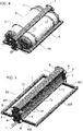
figure 5 is a perspective view at an enlarged scale of the auxiliary frame forming part of the assembly offigure 4 . - In
figure 1 , reference numeral 1 generally designates the supporting structure of a light duty vehicle, including a cabin frame 2 and avehicle frame 3. Avehicle frame 3 comprises a pair oflongitudinal beams 4 connected to each other by a plurality ofcross-members 5. - In the case of the present invention, the
longitudinal beams 4 of thevehicle frame 3 have a hollow structure of welded sheet metal, with anupper wall 4A, alower wall 4B, two outerlateral walls 4C and two innerlateral walls 4D. At least some of thecross-members 5 also have a hollow structure of welded sheet metal, including an upper wall, a lower wall and two lateral walls. In the case of the illustrated example, the ends of thecross-members 5 are rigidly connected to thelongitudinal beams 4 of thevehicle frame 3 by means ofintermediate supports 6 which are welded both to thecross-members 5 and thelongitudinal beams 4. The cabin frame 2 can be made in any known way, but in any case comprises a pair of longitudinal beams 7 which are rigidly connected, for example by welding, to the front ends of thelongitudinal beams 4 of thevehicle frame 3. To this end, in the illustrated example, the front ends of the longitudinal beams have couplingportions 4E having a U-shape which are engaged around the rear ends of the longitudinal beams 7 of the cabin frame 2. - According to the present invention, some of the
cross-members 5 of thevehicle frame 3 shown infigure 1 are replaced by assemblies 8 (see for examplefigure 3 ) for supportingtanks 9 for gaseous fuel (in particular CNG), which are in the form of substantially cylindrical containers, arranged in a horizontal position, with their axis directed transversely with respect to the longitudinal direction of thevehicle frame 3. - As shown in
figure 3 , thevehicle frame 3 is substantially identical to theframe 3 which has been described with reference tofigure 1 , except for thatcross-members 5 are omitted at the areas where theassemblies 8 must be mounted. - In
figures 2 ,3 , the parts in common to those offigure 1 are designated by the same reference numerals. In the example illustrated herein, the vehicle frame is provided with afirst assembly 8 for supporting three pairs oftanks 9, and afurther assembly 8 for supporting a single pair oftanks 9. It is clearly apparent that this arrangement is illustrated herein purely by way of non-limiting example. A vehicle frame can be indeed provided with any number of assemblies 8 (also a single assembly) and eachassembly 8 can be provided for supporting any number oftanks 9. - Each
assembly 8 includes anauxiliary frame 80 which supports thetanks 9 and is rigidly connected to thevehicle frame 3. -
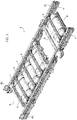
Figure 5 shows a perspective view of theframe 80 of anassembly 8 which supports a pair oftanks 9. In this embodiment, theauxiliary frame 80 has a quadrangular configuration, with twolongitudinal arms 80L and twotransverse arms 80T rigidly connected to each other. In the illustrated example, each of these arms is in the form of a metal bar with a square cross-section, so as to define a very rigid frame. Also with reference tofigure 5 , the central portions of the twolongitudinal arms 80L are connected to each after by a cross-member T which in the illustrated example is in the form of a hollow beam of welded sheet metal. The cross-member T has an upper wall T1, a lower wall T2 and two lateral walls T3. To the end surfaces of the cross-members T there are welded two connection plates P arranged at a vertical planes parallel to the longitudinal direction of the vehicle frame and having lugs projecting from the cross-section of the cross-members T, which are provided with holes or threaded bushes B, for engagement of screws for a rigid connection to thelongitudinal beams 4 of thevehicle frame 3. In the assembled condition (figure 2 ) the connection plates P are in contact with theinner walls 4D of thelongitudinal beam 4 of thevehicle frame 3 which are facing towards each other. - As diagrammatically shown by the arrows A in
figure 3 , theassemblies 8 are assembled from below on thevehicle frame 3. - Two flanges F axially project outwardly from the connection plates P of each cross-member T, these flanges acting as abutment elements adapted to engage the
lower walls 4B of the twolongitudinal beams 4 of thevehicle frame 3. In the specific example illustrated herein, each flange F is constituted by a flat portion of an L-shaped element welded to the respective plate P. - With reference to
figure 3 , in the case of the example illustrated herein, thevehicle frame 3 is provided, as indicated in the foregoing, both with anassembly 8 carrying a single pair oftanks 9 and with anassembly 8 carrying three pairs oftanks 9. This latter assembly also has anauxiliary frame 80 similar to that which has been described above with reference tofigure 5 , except for that thelongitudinal beams 80L have a longer extension and are connected to each other by many cross-members T. It is also absolutely possible, in place of asingle frame 80 carrying the three pairs oftanks 9, to provide threeframes 80 of the type shown infigure 5 , located at positions adjacent to each other. - An important feature of the present invention lies in that, due to the structure and the arrangement which have been described above, each
auxiliary frame 80 fulfills a structural strengthening function for thevehicle frame 3 which is absolutely similar to, or even more effective than, the structural function fulfilled by thecross-members 5 of the vehicle frame. As already indicated, in the area where the assemblies are provided, thecross-members 5 are omitted, but eachauxiliary frame 80 is able to fulfills the same function, due to the rigid configuration of this frame and due to the connection which has been described above between the ends of the cross-members T and thelongitudinal beams 4. In particular, theauxiliary frames 80 contribute to counteract the deformations of theframe 3 and above all they prevent undesired twisting deformations of this frame. - In this manner, the
auxiliary frames 80 carrying thegas tanks 9 also fulfill a safety function, by absorbing impact energy in the case of a vehicle collision. - With specific reference to the example in which each
assembly 8 carries gas tanks having the cylindrical configuration which has been described above, the lateral walls T3 of each beam T have a concave shape with a curved profile, so as to define a seat for the body of theadjacent tank 9. Furthermore, each wall T3 hasslots 10 through which securing metal belts 11 (figure 4 ) can be engaged, for securing thetanks 9 to theframes 80. - In the case of the specific example illustrated herein, to the
vehicle frame 3 there is associated also a counter-frame 30, comprising a pair oflongitudinal beams 31 connected to each other bycross-members 32. Thelongitudinal beams 31 are arranged above and along thelongitudinal beam 4 of thevehicle frame 3 and are rigidly connected thereto, for example by means of screws or by welding, in the case of the illustrated example, also the cross-members 32 are connected to thelongitudinal beams 31 with the interposition ofintermediate supports 33, each of which is welded both to the longitudinal beams and to the cross-members 32. - The counter-frame 30 is assembled from above (see arrow G in
figure 3 ) on thevehicle frame 3. As shown infigure 2 , in the assembled condition, thecounter-frame 3 acts as a spacer adapted to prevent a direct contact of the floor panel of the vehicle with thegas tanks 9. - As indicated in the foregoing, the invention is applicable also to the support of auxiliary units different from gas tanks, such as to the support of electric batteries.
- Naturally, while the principle of the invention remains the same, the details of construction and the embodiments may widely vary with respect to what has been described and shown purely by way of example, without departing from the scope of the present invention.
Claims (8)
- Light duty vehicle, comprising:- a vehicle frame (3), comprising a pair of longitudinal beams (4) connected to each other by a plurality of cross-members (5),- a cabin frame (2), comprising a pair of longitudinal beams (7) rigidly connected to the front ends of the longitudinal beams (4) of the vehicle frame (3),- at least one supporting structure (8) for auxiliary units (9) such as gaseous fuel tanks or electric batteries, carried by the vehicle frame (3),- said vehicle being characterized in that:- said supporting structure (8) for supporting the auxiliary units (9) comprises an auxiliary frame (80) which extends between the longitudinal beams (4) of the vehicle frame (3) and has at least two connection plates (P) arranged in vertical planes parallel to the longitudinal direction of the vehicle (3),- said connection plates (P) of the auxiliary frame (80) are in contact with mutually facing inner lateral walls (4D) of said longitudinal beams (4) of the vehicle frame (3) and are rigidly connected to said longitudinal beams (4) of the vehicle frame (3),so that said auxiliary frame (80) fulfills a structural function equivalent to the structural function of one or more of said cross-members (5) at an area of the vehicle frame (3) where said cross-members (5) are not provided or are omitted for leaving space for the auxiliary frame, and are therefore replaced by the latter.
- Vehicle according to claim 1, characterized in that said end plates (P) of the auxiliary frame (80) are provided with flanges (F) which project from said connection plates (P) and constitute abutment elements in engagement against lower walls (4B) of the two longitudinal beams (4) of the vehicle frame (3).
- Vehicle according to claim 2, characterized in that the auxiliary frame (80) has a quadrangular configuration including two longitudinal arms (80) and two transverse arms (80T) rigidly connected to each other and further comprising at least one cross-member (T) which connects the longitudinal arms (80L) to each other and which has its ends carrying said connection plates (P) arranged in vertical planes parallel to the longitudinal direction of the vehicle frame (3).
- Vehicle according to claim 3, characterized in that said at least one cross-member (T) of the auxiliary frame (80) is in the form of a hollow beam, with an upper wall (T1), a lower wall (T2), two lateral walls (T3) and end surfaces to which said connection plates (P) are rigidly connected.
- Vehicle according to claim 4, characterized in that said connection plates (P) have portions projecting outwardly with respect to the cross-section of the cross-member (T) which are provided with holes or threaded bushes (B) for engagement of screws for rigid connection to the longitudinal beams (4) of the vehicle frame (3).
- Vehicle according to claim 4, which is for housing a plurality of gaseous fuel tanks (9) having a substantially cylindrical shape, characterized in that said at least one cross-member (T) of the auxiliary frame (80) has concave lateral walls (T3) configured for defining a seat for respective gas tanks (9) arranged in a horizontal position with their axes arranged transversely to the longitudinal direction of the vehicle frame (3),
securing belts (11), for securing the tanks (9) to the auxiliary frame (70), being associated to each lateral wall (T3). - Vehicle according to claim 6, characterized in that it comprises a counter-frame (30) comprising a pair of longitudinal beams (31) extending above the longitudinal beams (4) of the vehicle frame (3), and rigidly connected thereto, and a plurality of cross-members (32) which connect the longitudinal beams (31) of the counter-frame (30) to each other, said counter-frame (30) acting as a spacer element for avoiding a direct contact of the gas tanks (9) with the vehicle floor panel.
- Vehicle according to claim 6, characterized in that it comprises one or more auxiliary frames (80), each auxiliary frame (80) being provided for supporting one or more gas tanks (9).
Priority Applications (5)
| Application Number | Priority Date | Filing Date | Title |
|---|---|---|---|
| EP19150888.6A EP3680150B1 (en) | 2019-01-09 | 2019-01-09 | Vehicle having a frame provided with a supporting structure for auxiliary units, in particular gas tanks or electric batteries |
| BR112021012409-8A BR112021012409B1 (en) | 2019-01-09 | 2019-08-13 | VEHICLE HAVING A FRAME PROVIDED WITH A SUPPORT FRAME FOR AUXILIARY UNITS, IN PARTICULAR GAS TANKS OR ELECTRIC BATTERIES |
| PCT/IB2019/056857 WO2020144498A1 (en) | 2019-01-09 | 2019-08-13 | Vehicle having a frame provided with a supporting structure for auxiliary units, in particular gas tanks or electric batteries |
| CN201980088535.XA CN113272205B (en) | 2019-01-09 | 2019-08-13 | Vehicle with a frame provided with a support structure for auxiliary units, in particular gas tanks or batteries |
| US17/421,093 US12194838B2 (en) | 2019-01-09 | 2019-08-13 | Vehicle having a frame provided with a supporting structure for auxiliary units, in particular gas tanks or electric batteries |
Applications Claiming Priority (1)
| Application Number | Priority Date | Filing Date | Title |
|---|---|---|---|
| EP19150888.6A EP3680150B1 (en) | 2019-01-09 | 2019-01-09 | Vehicle having a frame provided with a supporting structure for auxiliary units, in particular gas tanks or electric batteries |
Publications (2)
| Publication Number | Publication Date |
|---|---|
| EP3680150A1 true EP3680150A1 (en) | 2020-07-15 |
| EP3680150B1 EP3680150B1 (en) | 2021-02-24 |
Family
ID=65041555
Family Applications (1)
| Application Number | Title | Priority Date | Filing Date |
|---|---|---|---|
| EP19150888.6A Active EP3680150B1 (en) | 2019-01-09 | 2019-01-09 | Vehicle having a frame provided with a supporting structure for auxiliary units, in particular gas tanks or electric batteries |
Country Status (4)
| Country | Link |
|---|---|
| US (1) | US12194838B2 (en) |
| EP (1) | EP3680150B1 (en) |
| CN (1) | CN113272205B (en) |
| WO (1) | WO2020144498A1 (en) |
Cited By (2)
| Publication number | Priority date | Publication date | Assignee | Title |
|---|---|---|---|---|
| WO2023280385A1 (en) * | 2021-07-06 | 2023-01-12 | Volvo Truck Corporation | A suspension arrangement for an energy storage system |
| FR3130699A1 (en) * | 2021-12-16 | 2023-06-23 | Renault | Device for holding at least one energy storage element arranged under the floor of a motor vehicle |
Families Citing this family (8)
| Publication number | Priority date | Publication date | Assignee | Title |
|---|---|---|---|---|
| CA3161587C (en) * | 2019-12-16 | 2024-10-22 | Nikola Corporation | Integrated fuel storage system |
| DE202020103686U1 (en) * | 2020-06-26 | 2021-09-28 | Alois Kober Gmbh | Add-on chassis |
| JP7481221B2 (en) * | 2020-09-30 | 2024-05-10 | 株式会社Subaru | Fuel Cell Vehicles |
| CN112896317B (en) * | 2021-03-12 | 2023-03-14 | 中国重汽集团济南动力有限公司 | Short-wheelbase frame assembly and mounting method |
| KR102948443B1 (en) * | 2021-07-14 | 2026-04-06 | 현대자동차주식회사 | Vehicle floor structure |
| CN113635973A (en) * | 2021-07-16 | 2021-11-12 | 河南德力新能源汽车有限公司 | Truss type frame fuel cell cargo vehicle arrangement scheme |
| US12202543B2 (en) * | 2022-06-30 | 2025-01-21 | GM Global Technology Operations LLC | Modular pick-up truck chassis frame structure that maximizes the rechargeable energy storage system package volume for body-on-frame battery electric vehicle architectures introduction |
| CN117533157B (en) * | 2023-11-10 | 2024-09-13 | 陕西质镁融合科技有限公司 | Truss type light frame |
Citations (6)
| Publication number | Priority date | Publication date | Assignee | Title |
|---|---|---|---|---|
| US20040148778A1 (en) * | 2003-01-31 | 2004-08-05 | Fleming Sean M. | Method for manufacturing a vehicle frame assembly |
| US20050062251A1 (en) * | 2003-09-22 | 2005-03-24 | Ramsey John E. | Vehicle frame having air tank cross member |
| DE202010008375U1 (en) * | 2010-08-26 | 2011-11-28 | Al-Ko Kober Ag | chassis |
| JP2017039362A (en) * | 2015-08-18 | 2017-02-23 | スズキ株式会社 | Structure for mounting fuel gas tank for vehicle |
| EP3296186A1 (en) * | 2016-09-20 | 2018-03-21 | Schmitz Cargobull AG | Commercial vehicle with a structure and method for mounting a structure on a commercial vehicle |
| WO2018144780A1 (en) * | 2017-02-01 | 2018-08-09 | Agility Fuel Systems Llc | Tailgate fuel storage system |
Family Cites Families (10)
| Publication number | Priority date | Publication date | Assignee | Title |
|---|---|---|---|---|
| US5366246A (en) * | 1993-05-11 | 1994-11-22 | Navistar International Transportation Corp. | Vehicle fuel tank mounting and protective cage |
| US5658013A (en) * | 1995-09-20 | 1997-08-19 | The Babcock & Wilcox Company | Fuel tank for vehicles for holding and dispensing both a liquid and gaseous fuel therein |
| DE102006026118A1 (en) * | 2006-06-03 | 2007-12-06 | GM Global Technology Operations, Inc., Detroit | Mounting arrangement for gas tank of a motor vehicle |
| JP5061941B2 (en) * | 2008-02-18 | 2012-10-31 | 日産自動車株式会社 | Vehicle battery mounting structure |
| DE102010018093A1 (en) * | 2010-04-24 | 2011-10-27 | Gm Global Technology Operations Llc (N.D.Ges.D. Staates Delaware) | Tank module for a motor vehicle |
| DE102011014334A1 (en) * | 2011-03-18 | 2012-09-20 | GM Global Technology Operations LLC (n. d. Gesetzen des Staates Delaware) | Attachment structure for arranging gas tank in bottom portion of vehicle, has tank holders with fastening bands, fastening portions that are directly mounted on vehicle, and fastening regions with supporting foot mounted on vehicle |
| DE102012024842A1 (en) * | 2012-12-19 | 2014-06-26 | Daimler Ag | Component arrangement for motor car, has first composite component and shock-crash sensitive second composite component connected with each other by cylindrical acceleration-reduction device, where component are made of fiber material |
| WO2015017844A1 (en) * | 2013-08-02 | 2015-02-05 | Alternative Fuel Containers, Llc | Conformable fuel gas tank |
| EP3263424B1 (en) * | 2016-07-01 | 2018-10-03 | FCA Italy S.p.A. | Unit with longitudinal beam and front plate for a motor-vehicle structure |
| DE102016010138A1 (en) * | 2016-08-19 | 2017-02-16 | Daimler Ag | Fastening arrangement for a resource container between the longitudinal members of a frame of a truck |
-
2019
- 2019-01-09 EP EP19150888.6A patent/EP3680150B1/en active Active
- 2019-08-13 CN CN201980088535.XA patent/CN113272205B/en active Active
- 2019-08-13 WO PCT/IB2019/056857 patent/WO2020144498A1/en not_active Ceased
- 2019-08-13 US US17/421,093 patent/US12194838B2/en active Active
Patent Citations (6)
| Publication number | Priority date | Publication date | Assignee | Title |
|---|---|---|---|---|
| US20040148778A1 (en) * | 2003-01-31 | 2004-08-05 | Fleming Sean M. | Method for manufacturing a vehicle frame assembly |
| US20050062251A1 (en) * | 2003-09-22 | 2005-03-24 | Ramsey John E. | Vehicle frame having air tank cross member |
| DE202010008375U1 (en) * | 2010-08-26 | 2011-11-28 | Al-Ko Kober Ag | chassis |
| JP2017039362A (en) * | 2015-08-18 | 2017-02-23 | スズキ株式会社 | Structure for mounting fuel gas tank for vehicle |
| EP3296186A1 (en) * | 2016-09-20 | 2018-03-21 | Schmitz Cargobull AG | Commercial vehicle with a structure and method for mounting a structure on a commercial vehicle |
| WO2018144780A1 (en) * | 2017-02-01 | 2018-08-09 | Agility Fuel Systems Llc | Tailgate fuel storage system |
Cited By (2)
| Publication number | Priority date | Publication date | Assignee | Title |
|---|---|---|---|---|
| WO2023280385A1 (en) * | 2021-07-06 | 2023-01-12 | Volvo Truck Corporation | A suspension arrangement for an energy storage system |
| FR3130699A1 (en) * | 2021-12-16 | 2023-06-23 | Renault | Device for holding at least one energy storage element arranged under the floor of a motor vehicle |
Also Published As
| Publication number | Publication date |
|---|---|
| CN113272205A (en) | 2021-08-17 |
| WO2020144498A1 (en) | 2020-07-16 |
| US12194838B2 (en) | 2025-01-14 |
| BR112021012409A2 (en) | 2021-09-08 |
| US20220105799A1 (en) | 2022-04-07 |
| EP3680150B1 (en) | 2021-02-24 |
| CN113272205B (en) | 2023-05-05 |
Similar Documents
| Publication | Publication Date | Title |
|---|---|---|
| US12194838B2 (en) | Vehicle having a frame provided with a supporting structure for auxiliary units, in particular gas tanks or electric batteries | |
| US7513329B2 (en) | Vehicle rear body structure | |
| US7828330B2 (en) | Vehicle front body structure | |
| US9758029B2 (en) | Battery frame and vehicle battery mounting structure | |
| US8070217B2 (en) | Vehicle body rear part structure | |
| US11447184B2 (en) | Vehicle body lower structure | |
| US20170113728A1 (en) | Load path control mechanism | |
| KR101610766B1 (en) | Vehicle front structure | |
| US8210603B2 (en) | Detachable-body vehicle frame | |
| CN117508348A (en) | Vehicle subframes, vehicle body components, and vehicle | |
| JP2006111076A (en) | Body frame structure | |
| JP2017114162A (en) | Suspension cross member structure | |
| CN223266864U (en) | Platform skeleton structure and mining dump truck | |
| CN222496443U (en) | Auxiliary frame, chassis and vehicle | |
| EP4428014A1 (en) | Improved connection for vehicular frame of a public transport vehicle | |
| CN214607394U (en) | Vehicle with a steering wheel | |
| KR20200080886A (en) | Structure for Reinforcing Strength of Suspension Mount of Aluminum Frame | |
| CN217435837U (en) | Auxiliary frame and automobile body connecting support and automobile body | |
| CN217864012U (en) | Anticollision roof beam mounting panel and have its anticollision roof beam subassembly, vehicle | |
| CN115649285B (en) | Floor frame structure for cargo vehicle and cargo vehicle | |
| CN222246758U (en) | Stabilizer bar fixing support | |
| EP4175856B1 (en) | A vehicle | |
| JP5737097B2 (en) | Front body structure of the vehicle | |
| KR20110054339A (en) | Crossmember of vehicle | |
| BR112021012409B1 (en) | VEHICLE HAVING A FRAME PROVIDED WITH A SUPPORT FRAME FOR AUXILIARY UNITS, IN PARTICULAR GAS TANKS OR ELECTRIC BATTERIES |
Legal Events
| Date | Code | Title | Description |
|---|---|---|---|
| PUAI | Public reference made under article 153(3) epc to a published international application that has entered the european phase |
Free format text: ORIGINAL CODE: 0009012 |
|
| STAA | Information on the status of an ep patent application or granted ep patent |
Free format text: STATUS: REQUEST FOR EXAMINATION WAS MADE |
|
| 17P | Request for examination filed |
Effective date: 20191021 |
|
| AK | Designated contracting states |
Kind code of ref document: A1 Designated state(s): AL AT BE BG CH CY CZ DE DK EE ES FI FR GB GR HR HU IE IS IT LI LT LU LV MC MK MT NL NO PL PT RO RS SE SI SK SM TR |
|
| AX | Request for extension of the european patent |
Extension state: BA ME |
|
| RIC1 | Information provided on ipc code assigned before grant |
Ipc: B60K 1/04 20190101ALI20200713BHEP Ipc: B60K 15/07 20060101ALI20200713BHEP Ipc: B62D 21/12 20060101ALI20200713BHEP Ipc: B60K 15/063 20060101ALI20200713BHEP Ipc: B62D 21/02 20060101AFI20200713BHEP Ipc: B60K 15/03 20060101ALI20200713BHEP |
|
| GRAP | Despatch of communication of intention to grant a patent |
Free format text: ORIGINAL CODE: EPIDOSNIGR1 |
|
| STAA | Information on the status of an ep patent application or granted ep patent |
Free format text: STATUS: GRANT OF PATENT IS INTENDED |
|
| INTG | Intention to grant announced |
Effective date: 20200827 |
|
| GRAS | Grant fee paid |
Free format text: ORIGINAL CODE: EPIDOSNIGR3 |
|
| GRAA | (expected) grant |
Free format text: ORIGINAL CODE: 0009210 |
|
| STAA | Information on the status of an ep patent application or granted ep patent |
Free format text: STATUS: THE PATENT HAS BEEN GRANTED |
|
| AK | Designated contracting states |
Kind code of ref document: B1 Designated state(s): AL AT BE BG CH CY CZ DE DK EE ES FI FR GB GR HR HU IE IS IT LI LT LU LV MC MK MT NL NO PL PT RO RS SE SI SK SM TR |
|
| REG | Reference to a national code |
Ref country code: CH Ref legal event code: EP |
|
| REG | Reference to a national code |
Ref country code: AT Ref legal event code: REF Ref document number: 1364100 Country of ref document: AT Kind code of ref document: T Effective date: 20210315 |
|
| REG | Reference to a national code |
Ref country code: IE Ref legal event code: FG4D |
|
| REG | Reference to a national code |
Ref country code: DE Ref legal event code: R096 Ref document number: 602019002640 Country of ref document: DE |
|
| REG | Reference to a national code |
Ref country code: LT Ref legal event code: MG9D |
|
| REG | Reference to a national code |
Ref country code: NL Ref legal event code: MP Effective date: 20210224 |
|
| PG25 | Lapsed in a contracting state [announced via postgrant information from national office to epo] |
Ref country code: HR Free format text: LAPSE BECAUSE OF FAILURE TO SUBMIT A TRANSLATION OF THE DESCRIPTION OR TO PAY THE FEE WITHIN THE PRESCRIBED TIME-LIMIT Effective date: 20210224 Ref country code: FI Free format text: LAPSE BECAUSE OF FAILURE TO SUBMIT A TRANSLATION OF THE DESCRIPTION OR TO PAY THE FEE WITHIN THE PRESCRIBED TIME-LIMIT Effective date: 20210224 Ref country code: GR Free format text: LAPSE BECAUSE OF FAILURE TO SUBMIT A TRANSLATION OF THE DESCRIPTION OR TO PAY THE FEE WITHIN THE PRESCRIBED TIME-LIMIT Effective date: 20210525 Ref country code: BG Free format text: LAPSE BECAUSE OF FAILURE TO SUBMIT A TRANSLATION OF THE DESCRIPTION OR TO PAY THE FEE WITHIN THE PRESCRIBED TIME-LIMIT Effective date: 20210524 Ref country code: NO Free format text: LAPSE BECAUSE OF FAILURE TO SUBMIT A TRANSLATION OF THE DESCRIPTION OR TO PAY THE FEE WITHIN THE PRESCRIBED TIME-LIMIT Effective date: 20210524 Ref country code: PT Free format text: LAPSE BECAUSE OF FAILURE TO SUBMIT A TRANSLATION OF THE DESCRIPTION OR TO PAY THE FEE WITHIN THE PRESCRIBED TIME-LIMIT Effective date: 20210624 Ref country code: LT Free format text: LAPSE BECAUSE OF FAILURE TO SUBMIT A TRANSLATION OF THE DESCRIPTION OR TO PAY THE FEE WITHIN THE PRESCRIBED TIME-LIMIT Effective date: 20210224 |
|
| REG | Reference to a national code |
Ref country code: AT Ref legal event code: MK05 Ref document number: 1364100 Country of ref document: AT Kind code of ref document: T Effective date: 20210224 |
|
| PG25 | Lapsed in a contracting state [announced via postgrant information from national office to epo] |
Ref country code: SE Free format text: LAPSE BECAUSE OF FAILURE TO SUBMIT A TRANSLATION OF THE DESCRIPTION OR TO PAY THE FEE WITHIN THE PRESCRIBED TIME-LIMIT Effective date: 20210224 Ref country code: RS Free format text: LAPSE BECAUSE OF FAILURE TO SUBMIT A TRANSLATION OF THE DESCRIPTION OR TO PAY THE FEE WITHIN THE PRESCRIBED TIME-LIMIT Effective date: 20210224 Ref country code: NL Free format text: LAPSE BECAUSE OF FAILURE TO SUBMIT A TRANSLATION OF THE DESCRIPTION OR TO PAY THE FEE WITHIN THE PRESCRIBED TIME-LIMIT Effective date: 20210224 Ref country code: PL Free format text: LAPSE BECAUSE OF FAILURE TO SUBMIT A TRANSLATION OF THE DESCRIPTION OR TO PAY THE FEE WITHIN THE PRESCRIBED TIME-LIMIT Effective date: 20210224 Ref country code: LV Free format text: LAPSE BECAUSE OF FAILURE TO SUBMIT A TRANSLATION OF THE DESCRIPTION OR TO PAY THE FEE WITHIN THE PRESCRIBED TIME-LIMIT Effective date: 20210224 |
|
| PG25 | Lapsed in a contracting state [announced via postgrant information from national office to epo] |
Ref country code: IS Free format text: LAPSE BECAUSE OF FAILURE TO SUBMIT A TRANSLATION OF THE DESCRIPTION OR TO PAY THE FEE WITHIN THE PRESCRIBED TIME-LIMIT Effective date: 20210624 |
|
| PG25 | Lapsed in a contracting state [announced via postgrant information from national office to epo] |
Ref country code: CZ Free format text: LAPSE BECAUSE OF FAILURE TO SUBMIT A TRANSLATION OF THE DESCRIPTION OR TO PAY THE FEE WITHIN THE PRESCRIBED TIME-LIMIT Effective date: 20210224 Ref country code: EE Free format text: LAPSE BECAUSE OF FAILURE TO SUBMIT A TRANSLATION OF THE DESCRIPTION OR TO PAY THE FEE WITHIN THE PRESCRIBED TIME-LIMIT Effective date: 20210224 Ref country code: SM Free format text: LAPSE BECAUSE OF FAILURE TO SUBMIT A TRANSLATION OF THE DESCRIPTION OR TO PAY THE FEE WITHIN THE PRESCRIBED TIME-LIMIT Effective date: 20210224 Ref country code: AT Free format text: LAPSE BECAUSE OF FAILURE TO SUBMIT A TRANSLATION OF THE DESCRIPTION OR TO PAY THE FEE WITHIN THE PRESCRIBED TIME-LIMIT Effective date: 20210224 |
|
| REG | Reference to a national code |
Ref country code: DE Ref legal event code: R097 Ref document number: 602019002640 Country of ref document: DE |
|
| PG25 | Lapsed in a contracting state [announced via postgrant information from national office to epo] |
Ref country code: RO Free format text: LAPSE BECAUSE OF FAILURE TO SUBMIT A TRANSLATION OF THE DESCRIPTION OR TO PAY THE FEE WITHIN THE PRESCRIBED TIME-LIMIT Effective date: 20210224 Ref country code: SK Free format text: LAPSE BECAUSE OF FAILURE TO SUBMIT A TRANSLATION OF THE DESCRIPTION OR TO PAY THE FEE WITHIN THE PRESCRIBED TIME-LIMIT Effective date: 20210224 Ref country code: DK Free format text: LAPSE BECAUSE OF FAILURE TO SUBMIT A TRANSLATION OF THE DESCRIPTION OR TO PAY THE FEE WITHIN THE PRESCRIBED TIME-LIMIT Effective date: 20210224 |
|
| PLBE | No opposition filed within time limit |
Free format text: ORIGINAL CODE: 0009261 |
|
| STAA | Information on the status of an ep patent application or granted ep patent |
Free format text: STATUS: NO OPPOSITION FILED WITHIN TIME LIMIT |
|
| PG25 | Lapsed in a contracting state [announced via postgrant information from national office to epo] |
Ref country code: AL Free format text: LAPSE BECAUSE OF FAILURE TO SUBMIT A TRANSLATION OF THE DESCRIPTION OR TO PAY THE FEE WITHIN THE PRESCRIBED TIME-LIMIT Effective date: 20210224 Ref country code: ES Free format text: LAPSE BECAUSE OF FAILURE TO SUBMIT A TRANSLATION OF THE DESCRIPTION OR TO PAY THE FEE WITHIN THE PRESCRIBED TIME-LIMIT Effective date: 20210224 |
|
| 26N | No opposition filed |
Effective date: 20211125 |
|
| PG25 | Lapsed in a contracting state [announced via postgrant information from national office to epo] |
Ref country code: IS Free format text: LAPSE BECAUSE OF FAILURE TO SUBMIT A TRANSLATION OF THE DESCRIPTION OR TO PAY THE FEE WITHIN THE PRESCRIBED TIME-LIMIT Effective date: 20210624 |
|
| PG25 | Lapsed in a contracting state [announced via postgrant information from national office to epo] |
Ref country code: MC Free format text: LAPSE BECAUSE OF FAILURE TO SUBMIT A TRANSLATION OF THE DESCRIPTION OR TO PAY THE FEE WITHIN THE PRESCRIBED TIME-LIMIT Effective date: 20210224 |
|
| REG | Reference to a national code |
Ref country code: CH Ref legal event code: PL |
|
| REG | Reference to a national code |
Ref country code: BE Ref legal event code: MM Effective date: 20220131 |
|
| PG25 | Lapsed in a contracting state [announced via postgrant information from national office to epo] |
Ref country code: LU Free format text: LAPSE BECAUSE OF NON-PAYMENT OF DUE FEES Effective date: 20220109 |
|
| PG25 | Lapsed in a contracting state [announced via postgrant information from national office to epo] |
Ref country code: BE Free format text: LAPSE BECAUSE OF NON-PAYMENT OF DUE FEES Effective date: 20220131 |
|
| PG25 | Lapsed in a contracting state [announced via postgrant information from national office to epo] |
Ref country code: LI Free format text: LAPSE BECAUSE OF NON-PAYMENT OF DUE FEES Effective date: 20220131 Ref country code: CH Free format text: LAPSE BECAUSE OF NON-PAYMENT OF DUE FEES Effective date: 20220131 |
|
| PG25 | Lapsed in a contracting state [announced via postgrant information from national office to epo] |
Ref country code: IE Free format text: LAPSE BECAUSE OF NON-PAYMENT OF DUE FEES Effective date: 20220109 |
|
| GBPC | Gb: european patent ceased through non-payment of renewal fee |
Effective date: 20230109 |
|
| PG25 | Lapsed in a contracting state [announced via postgrant information from national office to epo] |
Ref country code: GB Free format text: LAPSE BECAUSE OF NON-PAYMENT OF DUE FEES Effective date: 20230109 |
|
| PG25 | Lapsed in a contracting state [announced via postgrant information from national office to epo] |
Ref country code: MK Free format text: LAPSE BECAUSE OF FAILURE TO SUBMIT A TRANSLATION OF THE DESCRIPTION OR TO PAY THE FEE WITHIN THE PRESCRIBED TIME-LIMIT Effective date: 20210224 Ref country code: CY Free format text: LAPSE BECAUSE OF FAILURE TO SUBMIT A TRANSLATION OF THE DESCRIPTION OR TO PAY THE FEE WITHIN THE PRESCRIBED TIME-LIMIT Effective date: 20210224 |
|
| PG25 | Lapsed in a contracting state [announced via postgrant information from national office to epo] |
Ref country code: HU Free format text: LAPSE BECAUSE OF FAILURE TO SUBMIT A TRANSLATION OF THE DESCRIPTION OR TO PAY THE FEE WITHIN THE PRESCRIBED TIME-LIMIT; INVALID AB INITIO Effective date: 20190109 |
|
| PG25 | Lapsed in a contracting state [announced via postgrant information from national office to epo] |
Ref country code: TR Free format text: LAPSE BECAUSE OF FAILURE TO SUBMIT A TRANSLATION OF THE DESCRIPTION OR TO PAY THE FEE WITHIN THE PRESCRIBED TIME-LIMIT Effective date: 20210224 |
|
| PG25 | Lapsed in a contracting state [announced via postgrant information from national office to epo] |
Ref country code: MT Free format text: LAPSE BECAUSE OF FAILURE TO SUBMIT A TRANSLATION OF THE DESCRIPTION OR TO PAY THE FEE WITHIN THE PRESCRIBED TIME-LIMIT Effective date: 20210224 |
|
| PGFP | Annual fee paid to national office [announced via postgrant information from national office to epo] |
Ref country code: FR Payment date: 20251217 Year of fee payment: 8 |
|
| PG25 | Lapsed in a contracting state [announced via postgrant information from national office to epo] |
Ref country code: SI Free format text: LAPSE BECAUSE OF FAILURE TO SUBMIT A TRANSLATION OF THE DESCRIPTION OR TO PAY THE FEE WITHIN THE PRESCRIBED TIME-LIMIT Effective date: 20210224 |
|
| PGFP | Annual fee paid to national office [announced via postgrant information from national office to epo] |
Ref country code: DE Payment date: 20251217 Year of fee payment: 8 |
|
| PGFP | Annual fee paid to national office [announced via postgrant information from national office to epo] |
Ref country code: IT Payment date: 20260107 Year of fee payment: 8 |