EP3296186A1 - Commercial vehicle with a structure and method for mounting a structure on a commercial vehicle - Google Patents
Commercial vehicle with a structure and method for mounting a structure on a commercial vehicle Download PDFInfo
- Publication number
- EP3296186A1 EP3296186A1 EP16189673.3A EP16189673A EP3296186A1 EP 3296186 A1 EP3296186 A1 EP 3296186A1 EP 16189673 A EP16189673 A EP 16189673A EP 3296186 A1 EP3296186 A1 EP 3296186A1
- Authority
- EP
- European Patent Office
- Prior art keywords
- chassis
- subframe
- brackets
- commercial vehicle
- consoles
- Prior art date
- Legal status (The legal status is an assumption and is not a legal conclusion. Google has not performed a legal analysis and makes no representation as to the accuracy of the status listed.)
- Withdrawn
Links
Images


Classifications
-
- B—PERFORMING OPERATIONS; TRANSPORTING
- B62—LAND VEHICLES FOR TRAVELLING OTHERWISE THAN ON RAILS
- B62D—MOTOR VEHICLES; TRAILERS
- B62D21/00—Understructures, i.e. chassis frame on which a vehicle body may be mounted
-
- B—PERFORMING OPERATIONS; TRANSPORTING
- B62—LAND VEHICLES FOR TRAVELLING OTHERWISE THAN ON RAILS
- B62D—MOTOR VEHICLES; TRAILERS
- B62D21/00—Understructures, i.e. chassis frame on which a vehicle body may be mounted
- B62D21/02—Understructures, i.e. chassis frame on which a vehicle body may be mounted comprising longitudinally or transversely arranged frame members
-
- B—PERFORMING OPERATIONS; TRANSPORTING
- B62—LAND VEHICLES FOR TRAVELLING OTHERWISE THAN ON RAILS
- B62D—MOTOR VEHICLES; TRAILERS
- B62D21/00—Understructures, i.e. chassis frame on which a vehicle body may be mounted
- B62D21/12—Understructures, i.e. chassis frame on which a vehicle body may be mounted assembled from readily detachable parts
-
- B—PERFORMING OPERATIONS; TRANSPORTING
- B62—LAND VEHICLES FOR TRAVELLING OTHERWISE THAN ON RAILS
- B62D—MOTOR VEHICLES; TRAILERS
- B62D33/00—Superstructures for load-carrying vehicles
- B62D33/077—Superstructures for load-carrying vehicles characterised by the connection of the superstructure to the vehicle frame
Definitions
- the invention relates to a utility vehicle with a chassis, on which at least one axle is mounted with wheels of the vehicle, and with a structure which is erected on the chassis.
- the invention relates to a method for mounting a structure on a chassis of a commercial vehicle, wherein at least one axle with wheels of the vehicle is mounted on the chassis.
- Commercial vehicles of the type in question here are in particular transport vehicles of the medium and small weight classes, ie vehicles with a total weight of typically up to 7.5 t, in particular up to 3.5 t, as used for example in regional delivery traffic ,
- Such commercial vehicles are usually provided by the vehicle manufacturer without the structure required for stowing the transported goods.
- the commercial vehicles then have a chassis which forms the central support structure of the vehicle.
- the chassis On the chassis of the drive unit, the drive train, the steering, the cab, etc. are stored.
- the chassis usually comprises two longitudinal members which extend at a distance from each other over the length of the vehicle.
- On these side rails or other, usually attached to the side members of the chassis components are then specialized Companies that mount custom-designed bodies according to customer requirements.
- the structures are typically designed as so-called "suitcases", ie cuboidal housings whose bottom, roof and walls consist of prefabricated panel components.
- suitable cases ie cuboidal housings whose bottom, roof and walls consist of prefabricated panel components.
- An example of such a case construction is in EP 2 524 856 B1 described.
- the superstructures may, for example, also be flatbed or tipper bodies or any other type of superstructure, as required or offered in practice in smaller commercial vehicles.
- the invention has achieved this object in that such a commercial vehicle is designed according to claim 1.
- a commercial vehicle according to the invention thus comprises a chassis, on which at least one axle is mounted with wheels of the vehicle, and a structure which is erected on the chassis bounded.
- the structure is supported by an auxiliary frame, which is supported on the chassis via individual brackets, which hold the subframe in relation to a flat surface on which the commercial vehicle is in a desired height, which is higher than that related to the flat surface Height of the top edge of the chassis in the area where the bodywork is mounted.
- the subframe has a platform independent of the actual dimensions of the vehicle chassis, the width and length of which are optimally adapted to the dimensions of the body.
- the structure itself can therefore be composed of standard components regardless of the type of vehicle. Its adaptation to the respective vehicle takes place via the subframe and the consoles supporting it.
- the brackets can in turn be standardized with respect to the connection to the subframe, so that in this respect the assembly effort is also minimized. Only the height and optionally width of the consoles must be adapted to the particular type of vehicle so that the subframe, with its top provided for placement of the construction, may be limited at the lower limit of the available free space above the chassis and the others Components of the vehicle is arranged.
- groups of identically shaped brackets are assembled, the groups differing in that the height of the fastening section of the brackets of one group depends on the height of the fastening section of the bracket the other group and / or the length of the support portion of the consoles of the one group is different from the length of the support portion of the console of the other group.
- Optimal way so many groups of consoles are provided that all types of vehicles, on each of which similar structures are mounted in each operation, are covered. Before assembly of a body on a certain type of vehicle then only the group of consoles must be determined, the dimensions of which are adapted to the dimensions of the vehicle type in question, that the provided for the construction subframe are mounted in the height provided for him on the chassis can.
- the width difference between an actual width of the chassis measured parallel to the flat surface and the area provided for securing the consoles can accordingly also be selected in step d) and a desired width of the subframe are determined.
- the at least one group of brackets selected for mounting is then determined such that not only the height of the attachment sections of the height difference determined in step d) but also the length of the support sections of the respective brackets assigned to the additionally determined width difference equivalent.
- the mounting of the subframe on the chassis can be done in two alternative ways.
- the consoles of the selected group of consoles are first placed with their support sections on the respectively assigned areas of the chassis and these consoles are fastened to the chassis. Then, the subframe is mounted on the attachment portions of the brackets mounted on the chassis.
- the consoles of the selected group of consoles are first identified with attached to their attachment sections on the subframe, then attached to the subframe brackets with their support sections placed on the respective associated areas of the chassis and finally the seated on the chassis consoles attached to the chassis.
- a particularly simple assembly results in a commercial vehicle according to the invention then, if this commercial vehicle includes a chassis with two longitudinal beams in the usual way today, on which are the subframes supporting consoles.
- a further variant of the invention facilitating the adaptation of the embodiment of a commercial vehicle according to the invention to any type of commercial vehicle is characterized in that the auxiliary frame comprises two auxiliary longitudinal beams aligned in the longitudinal direction of the commercial vehicle and composed of at least two auxiliary longitudinal beam sections.
- the length of the auxiliary longitudinal carrier sections is dimensioned such that the length of the auxiliary longitudinal carrier sections assembled to the respective auxiliary longitudinal carrier corresponds in total to the nominal length of the auxiliary longitudinal carrier.
- auxiliary longitudinal beams in the longitudinal direction of the auxiliary longitudinal beam allows the subframe to be provided as a kit comprising at least two groups of auxiliary longitudinal beam sections, the groups of auxiliary longitudinal beam sections being distinguished by the length of the associated auxiliary longitudinal beam sections, the auxiliary longitudinal beam sections of the groups otherwise, however, are identically shaped. From the groups of auxiliary longitudinal carrier sections, taking into account a target length of the subframe, respectively, auxiliary longitudinal carrier sections of different lengths are selected so that the total length of at least two auxiliary longitudinal carriers composed of the selected auxiliary longitudinal carrier sections is Target length of the subframe corresponds.
- the subframe is finally mounted, for which purpose, for example, transverse connectors or other stiffening components can be used to support the auxiliary longitudinal beams against each other and thus to ensure optimal stiffening of the subframe.
- auxiliary longitudinal beams by transverse connectors, such as auxiliary cross members or the like, can be dispensed with if the load capacity and dimensional stability of the subframe-supporting consoles and the auxiliary longitudinal beam alone is sufficient to ensure a proper level of the auxiliary longitudinal beams.
- the subframe thus consists only of the optionally combined in the manner described above Hilfslangvagen and strictly speaking thus no "frame” is from the term "subframe" according to the understanding of the invention, therefore, regardless of the shape of the respective construction all modules or components, which are supported on the one hand on selected according to the invention consoles on the chassis of the respective vehicle and on the other hand define the uppermost part of the auxiliary structure on which the construction of the commercial vehicle is constructed according to the invention.
- the entire assembly according to the invention should preferably be carried out without the use of welding methods or other methods in which it can lead to material changes as a result of heat and the like. Therefore, the invention provides according to a particularly effective practice for the embodiment, that the consoles with the chassis, the brackets with the subframe, the subframe with the structure and the components of the subframe are respectively exclusively positively or non-positively connected to each other.
- simple screw or rivet or so-called RandenbolzENSen be used, as in the DE 10248102 C1 are described.
- the positive or non-positive connections of the individual subframe sections can be made with each other by means of connecting straps which bridge the joints between the subframe sections.
- auxiliary longitudinal carrier sections of a respective auxiliary longitudinal carrier can also be supported by the fact that the auxiliary longitudinal carrier sections each have at their ends a bevelled in the height and longitudinal direction of the Hilfslangmoi coupless beveled edge ("bevel"). At these bevels the Hilfslangyesteil adoptede are placed together. It proves to be particularly advantageous in view of the rigidity of the connection between the Hilfslangyesteil Wunschen when in the bevels a shoulder is formed, against which in use the respective adjacent Hilfslangyesilia is supported at a transversely acting to the longitudinal extent of the Hilfslangyess load.
- the consoles may, as mentioned, shoe-shaped with a mounting portion and a right angle to the mounting portion arranged support portion, wherein the subframe on a support portion facing the contact surface of the mounting portion abuts and wherein the support portion supported with a remote from the mounting portion support surface on the associated component of the chassis is.
- brackets each have two or more openings arranged in the longitudinal direction of the respective section for passing through a fastening means, the auxiliary longitudinal beams and the associated component of the chassis likewise at its fastening section and its supporting section Having two or more openings for passing through the fastening means, each console at least one opening of the fastening portion having an opening of the associated auxiliary longitudinal carrier and an opening of the support portion are brought to an opening of the associated component of the chassis and each a fastening means brought by the aligned Openings is guided.
- similar, identically shaped brackets can be used to mount the respective subframe on different height chassis or in different nominal heights.
- the variation of the effective height of the attachment point provided for attaching the subframe to the attachment portion is effected by selecting the appropriate in each case based on the height of the attachment portion to the intended height desired opening.
- the length of the support section which is effectively used for the fastening can be determined by a selection of the respectively matching opening in the support section of the bracket and / or on the chassis component which is adapted to the respective chassis and body width, to which the relevant console is fastened.
- the invention can be realized in a particularly cost-effective manner when the consoles and the auxiliary longitudinal carriers are shaped sheet metal parts.
- the components of the subframe, in particular its auxiliary longitudinal carrier be designed as sheet metal profiles, based on simple Way, for example, by rolling or other continuous process molding, can be produced inexpensively in large quantities.
- the invention thus relates to a utility vehicle having a chassis and having a structure erected thereon.
- This structure is according to the invention supported by a subframe which is supported on the chassis via brackets, which hold him relative to a substrate on which the commercial vehicle is at a desired height which is higher than the reference to the level surface height of the upper edge of the Chassis in the area where the body is mounted.
- a commercial vehicle with a chassis, a subframe and a selection of groups of consoles are provided according to the invention, wherein the groups of consoles differ by a different height of the fastening sections or length of the support sections of the respective brackets assigned to the groups of consoles.
- the height difference between the actual height of the upper edge of the chassis in its intended for the attachment of the consoles areas and provided for the position of the subframe target height is determined and a group of consoles selected in which the height of their attachment sections corresponds to the determined height difference.
- the subframe is fastened to the chassis via the brackets and the superstructure is mounted on the subframe.
- a transporter of the 3.5-tonne class typically has a chassis 2 constructed as a ladder frame construction with the drive axle 3 and steered axle 4 mounted thereon, a drive unit supported by the chassis and located in the front area of the commercial vehicle 1 and an over it, arranged in the front region of the vehicle 1 cab 5 carries.
- the commercial vehicle 1 In the delivery state, the commercial vehicle 1 has no special features, but corresponds to the standard of the respective manufacturer.
- the chassis 2 has two extending in the longitudinal direction L of the commercial vehicle 1, designed as steel profiles long beam 8.9, which are aligned parallel to each other and connected by cross members 10 together are.
- the rest of the structure of the chassis 2 corresponds to the usual standard construction of the respective manufacturer.
- an auxiliary frame 11 is mounted on the long beams 8.9.
- the subframe 11 is aligned parallel to one another by two auxiliary longitudinal beams 12, 13 and two auxiliary longitudinal beams 12, 13 and supports auxiliary crossbeams 14, 15 at a distance. If necessary, the auxiliary crossbeams 14, 15 can also be dispensed with if the carrying capacity and rigidity of the auxiliary longitudinal beams 12, 13 alone suffice for the support of the body A. In this case, the subframe 11 consists only of the auxiliary longitudinal beams 11,12, which are handled during assembly as separate components.
- the width BH of the auxiliary frame 11 measured transversely to the longitudinal extent L and parallel to the base on which the commercial vehicle 1 stands is wider than the width BC measured between the outer edges of the auxiliary longitudinal beams 12, 13, but smaller than the width corresponding to the statutory maximum width BA of the structure 7.
- the width BH of the auxiliary frame 11 is additionally dimensioned such that the auxiliary frame 11 fits between the drive wheels R of the commercial vehicle 1.
- the auxiliary longitudinal beams 12, 13 are each composed of two auxiliary longitudinal beam sections 12a, 12b and 13a, 13b. These auxiliary longitudinal carrier sections 12a, 12b have each been selected from different groups of auxiliary longitudinal carrier sections, which are stored in operation, which carries out the assembly of the superstructure 7 on the commercial vehicle 1, or at the manufacturer of the superstructure 7.
- Each Hilfslangyesteil Sharing a certain length is in each case combined into one group. For example, six groups of different lengths, but otherwise identically shaped Auxiliary Langismeteil congressen kept.
- the lengths of the auxiliary longitudinal carrier sections of the individual groups are matched to one another such that by combining two or more auxiliary longitudinal carrier sections which are taken from one of the groups or several different groups and combined with each other to form an auxiliary longitudinal carrier 12, 13, the overall length LH of the respective auxiliary frame 11 associated auxiliary longitudinal beams 12,13 to the available on the respective commercial vehicle 1 for the assembly of the body 7 available length LC and the length LA of the body 7 can be adjusted.
- the auxiliary longitudinal beam sections 12a, 13a having a length LH 'and the fourth group of auxiliary longitudinal beam sections having a length LH "shorter than the length LH', the auxiliary longitudinal beam sections 12b , 13b, so that a long beam 12,13 with the required total length LH LH '+ LH "is obtained.
- auxiliary longitudinal support sections 12a, 12b, 13a, 13b are each formed as U-profiles from a sheet metal. In order to minimize weight, openings are formed in a central region of their base section 16 at regular intervals. In addition, over the entire available length at the respective upper leg portion 17 and lower leg portion 18 adjacent edge portions of the base portion 16 of the Hilfslangyesteil foundede 12a - 13b each have a number of uniformly spaced circular through holes 19.
- the auxiliary longitudinal support sections 12a 13b in the region of its base section 16 their ends over their height HT bevelled bevels 20,21.
- the chamfers 20,21 are mirror-symmetrically aligned with respect to the longitudinal extension L center of the respective Hilfslangyesteil 12a-13b, so that in each case a leg portion 17 of the Hilfslangyesteil Federatione 12a-13b is shorter than her other leg portion 18.
- the chamfer 20, 21 respectively merges into a shoulder 22, 23 whose front-side contact surface is oriented at right angles to the respective leg section 17, 18.
- the auxiliary longitudinal beam sections 12a, 12b and 13a, 13b are correspondingly butted together with their associated ends such that the longer leg section 18 is at the top of an auxiliary longitudinal beam section 12a, 13a, whereas the respective other auxiliary longitudinal beam section 12b, 13b is aligned so that the shorter leg portion 17 is above.
- the auxiliary longitudinal beams 12, 13 are aligned such that their leg sections 17, 18 face one another, their base sections 16 thus facing the outside of the auxiliary longitudinal beam 11, respectively.
- the joining zone F1, F2 between the auxiliary longitudinal support sections 12a, 12b and 13a, 13b is then bridged to the auxiliary crossmember 14,15 associated inner sides of their base portions 16, each with a connecting plate 24, for example, by conventional, guided through the openings 19 screw or RändelbolzMISen 26 positively and positively connected with each other.
- auxiliary cross member 14,15 regardless of the compound of To fix auxiliary longitudinal support sections 12a-13b using the provided through holes 19 on the auxiliary longitudinal beams 12,13, as in Fig. 1 and 2 for the driver's cab 5 associated auxiliary cross member 15 is shown.
- the respective shoe-like brackets 27, 28 have a fastening section 29 and a support section 30 oriented at right angles thereto.
- the attachment portion 29 has on its the support portion 30 associated side a contact surface 31 for the outer surface 16a of the base portion 16 of the respective associated auxiliary longitudinal support 12,13, whereas the support portion 30 on its side facing away from the mounting portion 29 underside has a support surface 32 which is perpendicular with respect to the contact surface 31 is aligned and is provided for placement on the upper side 33 of the longitudinal beam 8.9 of the chassis 2.
- In the contact surfaces 31 of the brackets 27,28 spaced slot-shaped and parallel to the support surface 32 extending through openings 34,35 are formed in the respective wall of the mounting portion.
- the spacing of the passage openings 34, 35 corresponds to the spacing of the rows of passage openings 19 in the base sections 16 of the auxiliary longitudinal support sections 12a-13b.
- the brackets 27 each have a pair of passage openings 34, 35 arranged in this way, whereas in the case of the brackets 28, which are approximately twice as wide as the brackets 27, two pairs of passage openings 34, 35 are formed in the contact surface 31 of the fastening section 29 ,
- the support portion 30 of the brackets 27 has two correspondingly arranged passage openings 36, 37, whereas in the support portion 30 of the brackets 28 only one passage opening 36 is provided.
- the length LS of the support portion 30 and the position of its passage openings 36,37 and the height HB of the mounting portion 29 and the position of its through holes 34,35 are chosen so that the support portions 30 of the brackets 27,28 securely on the top 33 of the long beam 8.9 sit and on the other hand, the subframe 11 with the outside 16a of their respective auxiliary longitudinal beams 12,13 abut against the contact surface 31 of the mounting portion 29.
- the brackets 27,28 bridge in this way the width difference between the present in the region of the side members 8,9 width BC of the chassis 2 and the width BH of the subframe 11 is present, and hold the auxiliary longitudinal beams 12,13 simultaneously so high the longitudinal beams 8, 9 that its upper edge is held at a prescribed nominal height HSoll above the level ground U, on which the commercial vehicle 1 stands, and in the case of a finished commercial vehicle ( Fig. 7 ) mounted on the auxiliary longitudinal beam 12,13 structure 7 is accordingly free above the drive wheels R of the commercial vehicle 1.
- the brackets 27, 28 have each been selected from different groups of brackets, which, like the auxiliary longitudinal beam sections 12 a - 13 b, are stored in operation, which carries out the assembly of the body 7 on the commercial vehicle 1, or the manufacturer of the body 7.
- the respective consoles grouped into one of the groups differ from the consoles of the other groups by the length LS of their support sections 30 and / or the height HB of their attachment sections 29.
- Another distinguishing criterion is the effective length LS of the support sections 30 for the support essential position of the through holes 36,37 or for fixing the respective assigned auxiliary longitudinal support 12,13 effectively usable height determining position of the slot-shaped through holes 34,35 in the contact surface 31 be. For example, ten groups of different sized, but otherwise identically shaped consoles are kept ready.
- the dimensions of the consoles of the individual groups are tuned so that by selecting consoles from a particular group in the respective commercial vehicle 1, on which the body 7 is to be mounted, existing height difference between the actual height Hist the top of the chassis 2 in the for the Fixing the consoles provided areas (here the top 33 of the long beam 8.9) and provided for the position of the subframe 11 target height Hsoll, can be bridged.
- the dimensions of the waiting consoles are determined so that the width difference between the width BH of the subframe 11 and the width BC in the area of the longitudinal beams 8, 9 of the chassis 2 can be bridged over the support sections 30 of the respective selected consoles.
- the consoles grouped together into groups are dimensioned so that at least one group of matching consoles is available for each common vehicle type and each associated subframe 11 or assembly 7.
- brackets 27, 28 are selected in the manner described above from the waiting groups of brackets.
- brackets 27, 28 are fastened with their fastening sections 29 on the upper side 33 of the associated longitudinal beams 8, 9 to through openings introduced there by means of suitable screw or knurled bolt connections.
- one of the wider consoles 28 is arranged on the driver's cab 5 assigned area to be able to safely absorb the higher loads occurring there.
- four of the narrower consoles 27 are arranged distributed per longitudinal beam 8,9 at equal intervals over the available length.
- the subframe 11 is placed between the mounting portions 30 of the brackets 27,28 and also connected by screw or Rändelbolzemblen with the brackets 27,28. If the subframe 11 does not comprise an auxiliary cross member 14, 15, the subframe 11 thus consists only of the auxiliary longitudinal beams 12, 13, then the auxiliary longitudinal beams 12, 13 are placed in two consecutively completed working steps on the fastening sections 29 of the respective associated brackets 27, 28 and fastened there ,
- auxiliary crossmember 14,15 Regardless of whether they are connected to each other as part of the subframe shown here in the figures 11 on the auxiliary crossmember 14,15 or whether they are renounced independently of the Befest Trentsabschitte 29 of the consoles 27,28, waiving the auxiliary crossbar 14,15 the connection of the respective auxiliary longitudinal beams 12,13 on the brought to coincidence openings 19 and 34,35, wherein by the slot shape of the passage openings 34,35 a tolerance compensation is made possible.
- the height of the passage openings 34,35 over the support portion 30 of the brackets 27,28 is taking into account the height of the base portion 16 of the Hilfslangyesteil Publishede 12,13 dimensioned so that the subframe 11 at a distance from the upper edge of the support portions 30 to the brackets 27,28 is held. In this way prevents height tolerances hinder the assembly of the subframe 11 to the brackets 27,28.
- the superstructure 7 is erected thereon in the manner known in the art.
Abstract
Die Erfindung betrifft ein Nutzfahrzeug mit einem Chassis (2) und mit einem darauf errichteten Aufbau (7). Dieser wird erfindungsgemäß von einem Hilfsrahmen (11) getragen, der auf dem Chassis (2) über Konsolen (27,28) abgestützt ist, die ihn bezogen auf einen Untergrund (U), auf dem das Nutzfahrzeug (1) steht, in einer Sollhöhe (Hsoll) halten, die höher ist als die auf den ebenen Untergrund (U) bezogene Höhe (Hist) der Oberkante des Chassis (2) in dem Bereich (6), in dem der Aufbau (7) montiert ist. Auf diese Weise lassen sich auf dem Nutzfahrzeug unabhängig vom bei ihm vorhandenen Chassis Aufbauten montieren. Hierzu werden erfindungsgemäß ein Nutzfahrzeug (1) mit einem Chassis (2), ein Hilfsrahmen (11) und eine Auswahl von Gruppen von Konsolen bereitgestellt, wobei sich die Gruppen von Konsolen durch eine unterschiedliche Höhe (HB) der Befestigungsabschnitte (29) oder Länge (LS) der Stützabschnitte (30) der den Gruppen von Konsolen jeweils zugeordneten Konsolen unterscheiden. Dann wird die Höhendifferenz zwischen der Isthöhe (Hist) der Oberkante des Chassis (2) in dessen für die Befestigung der Konsolen (27,28) vorgesehenen Bereichen und einer für die Position des Hilfsrahmens (11) vorgesehenen Sollhöhe (Hsoll) bestimmt und eine Gruppe von Konsolen (27,28) ausgewählt, bei denen die Höhe (HB) ihrer Befestigungsabschnitte der ermittelten Höhendifferenz entspricht. Schließlich wird der Hilfsrahmen über die Konsolen auf dem Chassis befestigt und der Aufbau auf dem Hilfsrahmen montiert.The invention relates to a utility vehicle with a chassis (2) and with a structure erected thereon (7). This is inventively supported by a subframe (11) which is supported on the chassis (2) via brackets (27,28), which relates to a substrate (U) on which the commercial vehicle (1), in a desired height (Hsoll) which is higher than the height (Hist) of the upper edge of the chassis (2) in the area (6) in which the superstructure (7) is mounted, relative to the level ground (U). In this way, can be mounted on the commercial vehicle regardless of the existing chassis chassis. For this purpose, a commercial vehicle (1) with a chassis (2), an auxiliary frame (11) and a selection of groups of consoles are provided according to the invention, wherein the groups of consoles are characterized by a different height (HB) of the attachment sections (29) or length ( LS) of the support portions (30) of the groups of consoles respectively associated consoles. Then, the height difference between the actual height (Hist) of the upper edge of the chassis (2) in its intended for the attachment of the brackets (27,28) areas and a for the position of the subframe (11) provided target height (Hsoll) is determined and a group selected by brackets (27,28), in which the height (HB) of their attachment sections corresponds to the determined height difference. Finally, the subframe is fastened to the chassis via the brackets and the superstructure is mounted on the subframe.
Description
Die Erfindung betrifft ein Nutzfahrzeug mit einem Chassis, an dem mindestens eine Achse mit Rädern des Fahrzeugs gelagert ist, und mit einem Aufbau, der auf dem Chassis errichtet ist.The invention relates to a utility vehicle with a chassis, on which at least one axle is mounted with wheels of the vehicle, and with a structure which is erected on the chassis.
Darüber hinaus betrifft die Erfindung ein Verfahren zum Montieren eines Aufbaus auf einem Chassis eines Nutzfahrzeugs, wobei an dem Chassis mindestens eine Achse mit Rädern des Fahrzeugs gelagert ist.Moreover, the invention relates to a method for mounting a structure on a chassis of a commercial vehicle, wherein at least one axle with wheels of the vehicle is mounted on the chassis.
Bei Nutzfahrzeugen der hier in Rede stehenden Art handelt es sich insbesondere um Transportfahrzeuge der mittleren und kleinen Gewichtsklasse, also Fahrzeuge mit einem Gesamtgewicht von typischerweise bis zu 7,5 t, insbesondere bis zu 3,5 t, wie sie beispielsweise im regionalen Lieferverkehr eingesetzt werden.Commercial vehicles of the type in question here are in particular transport vehicles of the medium and small weight classes, ie vehicles with a total weight of typically up to 7.5 t, in particular up to 3.5 t, as used for example in regional delivery traffic ,
Solche Nutzfahrzeuge werden üblicherweise vom Fahrzeughersteller ohne den zum Verstauen des Transportguts benötigten Aufbau bereitgestellt. Im Auslieferungszustand weisen die Nutzfahrzeuge dann ein Chassis auf, das die zentrale Tragstruktur des Fahrzeugs bildet. An dem Chassis sind das Antriebsaggregat, der Antriebsstrang, die Lenkung, die Fahrerkabine etc. gelagert. Dabei umfasst das Chassis üblicherweise zwei Längsträger, die sich beabstandet zueinander über die Länge des Fahrzeugs erstrecken. Auf diesen Längsträgern oder andere, in der Regel an die Längsträger angebaute Bauteile des Chassis werden dann von spezialisierten Unternehmen die jeweils an den Kundenwunsch angepassten Aufbauten montiert.Such commercial vehicles are usually provided by the vehicle manufacturer without the structure required for stowing the transported goods. In the delivery state, the commercial vehicles then have a chassis which forms the central support structure of the vehicle. On the chassis of the drive unit, the drive train, the steering, the cab, etc. are stored. In this case, the chassis usually comprises two longitudinal members which extend at a distance from each other over the length of the vehicle. On these side rails or other, usually attached to the side members of the chassis components are then specialized Companies that mount custom-designed bodies according to customer requirements.
Die Aufbauten werden dabei typischerweise als so genannte "Koffer" ausgebildet, d.h. quaderförmigen Gehäusen, deren Boden, Dach und Wände aus vorgefertigten Paneelbauteilen bestehen. Ein Beispiel für einen derartigen Kofferaufbau ist in der
Unabhängig von ihrer Art und Ausführung ergibt sich bei der Montage der Aufbauten dadurch ein Problem, dass die Höhe, in der der Aufbau über dem Chassis des jeweiligen Nutzfahrzeugs montiert werden kann, von Fahrzeughersteller zu Fahrzeughersteller konstruktionsbedingt unterschiedlich ist. So führen nicht nur unterschiedliche Dimensionierungen der Bauteile des Chassis, sondern auch die Rädergröße sowie die unterschiedliche Gestaltungen von Radkästen und sonstigen Anbauteilen dazu, dass der freie Bereich, in dem der Aufbau montiert werden kann, von Fahrzeugtyp zu Fahrzeugtyp unterschiedlich hoch liegt.Regardless of their nature and design, there is a problem with the assembly of the structures in that the height at which the structure can be mounted above the chassis of the respective commercial vehicle differs from vehicle manufacturer to vehicle manufacturer due to the design. So lead not only different dimensions of the components of the chassis, but also the size of the wheels and the different designs of wheel arches and other attachments to the fact that the free area in which the structure can be mounted varies from vehicle to vehicle type.
In der Praxis wird dieses Problem dadurch gelöst, dass für jeden Fahrzeugtyp individuell abgestimmte Konsolen, Zwischenträger oder desgleichen vorgesehen werden, die auf dem Chassis montiert werden und die Höhendifferenz zwischen dem Chassis und dem Beginn des für die Montage des Aufbaus zur Verfügung stehenden freien Bereichs überbrücken. Die Anpassung, Fertigung und Bevorratung der hierzu erforderlichen, individuell gefertigten Bauteile ist zeit- und kostenaufwändig. Darüber hinaus bringt die Notwendigkeit der Montage der individuell gefertigten Bauteile insbesondere dann einen vermehrten Montageaufwand mit sich, wenn beispielsweise in einem handwerklich arbeitenden Betrieb in Kleinstauflagen Aufbauten auf unterschiedliche Fahrzeugtypen montiert werden sollen.In practice, this problem is solved by providing for each vehicle type individually matched consoles, subcarriers or the like, which are mounted on the chassis and bridge the height difference between the chassis and the beginning of the available for the assembly of the structure free area , The adaptation, production and storage of the required individually manufactured components is time consuming and costly. In addition, the need for mounting the custom-made components in particular brings an increased installation effort when, for example, in a manual operation in Small runs Superstructures to be mounted on different vehicle types.
Vor diesem Hintergrund hat sich die Aufgabe ergeben, ein Nutzfahrzeug so zu gestalten, dass sich auf ihm unabhängig vom jeweils bei ihm vorhandenen Chassis auf einfache und kostengünstige Weise ein Aufbau der voranstehend erläuterten Art montieren lässt.Against this background, the task has arisen that a commercial vehicle to be designed so that it can be mounted on it regardless of the existing chassis in each case in a simple and cost-effective manner, a structure of the type described above.
Darüber hinaus sollte ein Verfahren zur Montage von Aufbauten auf Nutzfahrzeugen angegeben werden, das es auf kostengünstige und praxisgerechte Art erlaubt, derartige Aufbauten auf beliebigen, jeweils mit einem Chassis ausgestatteten Nutzfahrzeugtypen zu montieren.In addition, a method for assembling superstructures on commercial vehicles should be specified, which makes it possible in a cost-effective and practical way to assemble such superstructures on any type of commercial vehicle equipped with a chassis.
In Bezug auf das Nutzfahrzeug hat die Erfindung diese Aufgabe dadurch gelöst, dass ein solches Nutzfahrzeug gemäß Anspruch 1 ausgebildet ist.With respect to the commercial vehicle, the invention has achieved this object in that such a commercial vehicle is designed according to
Ein die voranstehend genannte Aufgabe erfindungsgemäß lösendes Verfahren ist in Anspruch 12 angegeben.An object according to the above-mentioned method according to the invention is specified in
Vorteilhafte Ausgestaltungen der Erfindung sind in den abhängigen Ansprüchen angegeben und werden nachfolgend wie der allgemeine Erfindungsgedanke im Einzelnen erläutert.Advantageous embodiments of the invention are specified in the dependent claims and are explained below as the general inventive concept in detail.
Ein erfindungsgemäßes Nutzfahrzeug umfasst somit ein Chassis, an dem mindestens eine Achse mit Rädern des Fahrzeugs gelagert ist, und einen Aufbau, der auf dem Chassis errichtet ist umgrenzt.A commercial vehicle according to the invention thus comprises a chassis, on which at least one axle is mounted with wheels of the vehicle, and a structure which is erected on the chassis bounded.
Erfindungsgemäß ist dabei der Aufbau von einem Hilfsrahmen getragen, der auf dem Chassis über einzelne Konsolen abgestützt ist, die den Hilfsrahmen bezogen auf einen ebenen Untergrund, auf dem das Nutzfahrzeug steht, in einer Sollhöhe halten, die höher ist als die auf den ebenen Untergrund bezogene Höhe der Oberkante des Chassis in dem Bereich, in dem der Aufbau montiert ist.According to the invention, the structure is supported by an auxiliary frame, which is supported on the chassis via individual brackets, which hold the subframe in relation to a flat surface on which the commercial vehicle is in a desired height, which is higher than that related to the flat surface Height of the top edge of the chassis in the area where the bodywork is mounted.
Dadurch, dass bei einem erfindungsgemäßen Fahrzeug der jeweilige Aufbau auf einem Hilfsrahmen errichtet ist und dieser Hilfsrahmen über Konsolen auf dem Chassis des Fahrzeugs abgestützt ist, ist der für eine ordnungsgemäße Abstützung und Befestigung des Aufbaus auf dem Chassis erforderliche Aufwand deutlich minimiert. Der Hilfsrahmen bietet eine von den tatsächlichen Abmessungen des Fahrzeug-Chassis unabhängige Plattform, deren Breite und Länge optimal an die Abmessungen des Aufbaus angepasst sind. Der Aufbau selbst kann daher unabhängig vom jeweiligen Fahrzeugtyp aus Standardbauteilen zusammengesetzt sein. Seine Anpassung an das jeweilige Fahrzeug erfolgt über den Hilfsrahmen und die ihn stützenden Konsolen.The fact that in a vehicle according to the invention, the respective structure is erected on a subframe and this subframe is supported by brackets on the chassis of the vehicle, the effort required for proper support and attachment of the structure on the chassis is significantly minimized. The subframe has a platform independent of the actual dimensions of the vehicle chassis, the width and length of which are optimally adapted to the dimensions of the body. The structure itself can therefore be composed of standard components regardless of the type of vehicle. Its adaptation to the respective vehicle takes place via the subframe and the consoles supporting it.
Die Konsolen können wiederum in Bezug auf den Anschluss an den Hilfsrahmen standardisiert ausgebildet sein, so dass insoweit der Montageaufwand ebenfalls minimiert ist. Lediglich die Höhe und gegebenenfalls Breite der Konsolen muss an den jeweiligen Fahrzeugtyp so angepasst sein, dass der Hilfsrahmen mit seiner zum Aufsetzen des Aufbaus vorgesehenen Oberseite an der Untergrenze des für den Aufbau zur Verfügung stehenden freien Raums oberhalb des Chassis und der anderen diesen Raum möglicherweise beschränkenden Bauteile des Fahrzeugs angeordnet ist.The brackets can in turn be standardized with respect to the connection to the subframe, so that in this respect the assembly effort is also minimized. Only the height and optionally width of the consoles must be adapted to the particular type of vehicle so that the subframe, with its top provided for placement of the construction, may be limited at the lower limit of the available free space above the chassis and the others Components of the vehicle is arranged.
Dem einem erfindungsgemäßen Nutzfahrzeug zu Grunde liegenden Konzept entsprechend sieht das erfindungsgemäße Verfahren zum Montieren eines Aufbaus auf einem Chassis eines Nutzfahrzeugs, wobei an dem Chassis mindestens eine Achse mit Rädern des Fahrzeugs gelagert ist, umfassend folgende Arbeitsschritte vor:
- a) Bereitstellen des mit dem Chassis ausgestatteten Nutzfahrzeugs;
- b) Bereitstellen einer Auswahl von Gruppen von Konsolen, die jeweils einen Befestigungsabschnitt und einen rechtwinklig dazu angeordneten Stützabschnitt aufweisen, wobei sich die Gruppen von Konsolen durch eine unterschiedliche Höhe der Befestigungsabschnitte oder Länge der Stützabschnitte der den Gruppen von Konsolen zugeordneten Konsolen unterscheiden;
- c) Bereitstellen eines Hilfsrahmens,
- d) Bestimmen der Höhendifferenz zwischen der Isthöhe der Oberkante des Chassis in dessen für die Befestigung der Konsolen vorgesehenen Bereichen und einer für die Position des Hilfsrahmens vorgesehenen Sollhöhe, wobei die Isthöhe der für die Befestigung der Konsolen vorgesehenen Bereiche des Chassis und die Sollhöhe der Position des Hilfsrahmens jeweils über einem ebenen Untergrund, auf dem das Nutzfahrzeug steht, gemessen wird,
- e) Auswählen mindestens einer Gruppe von Konsolen, bei denen die Höhe ihrer Befestigungsabschnitte der im Arbeitsschritt d) ermittelten Höhendifferenz entspricht;
- f1) Aufsetzen der Stützabschnitte (30) der Konsolen (27,28) der ausgewählten Gruppe von Konsolen (27,28) auf den jeweils zugeordneten Bereichen des Chassis (2), Befestigen der Konsolen (27,28) am Chassis (2) und Montieren des Hilfsrahmens (11) an den Befestigungsabschnitten (30) der am Chassis (2) befestigten Konsolen (27,28);
oder - f2) Montieren der Konsolen (27,28) der ausgewählten Gruppe von Konsolen (27,28) mit ihren Befestigungsabschnitten (30) am Hilfsrahmen (11), Aufsetzen der Stützabschnitte (30) der am Hilfsrahmen (11) befestigten Konsolen (27,28) auf den jeweils zugeordneten Bereichen des Chassis (2) und Befestigen der Konsolen (27,28) am Chassis (2);
- g) Montieren des Aufbaus auf dem Hilfsrahmen.
- a) providing the commercial vehicle equipped with the chassis;
- b) providing a selection of groups of consoles, each having a mounting portion and a support portion arranged at right angles thereto, said groups of consoles extending through a different heights of the mounting portions or length of the support portions of the groups of consoles associated consoles;
- c) providing a subframe,
- d) determining the height difference between the actual height of the upper edge of the chassis in its intended for the attachment of the consoles areas and provided for the position of the subframe target height, the actual height of the intended for the attachment of the console areas of the chassis and the desired height of the position of the Subframe above a level surface on which the commercial vehicle stands, is measured,
- e) selecting at least one group of consoles, in which the height of their attachment sections corresponds to the height difference determined in step d);
- f1) placing the support sections (30) of the consoles (27, 28) of the selected group of consoles (27, 28) on the respectively associated areas of the chassis (2), securing the consoles (27, 28) to the chassis (2) and Mounting the subframe (11) to the attachment portions (30) of the brackets (27, 28) fixed to the chassis (2);
or - f2) mounting the brackets (27, 28) of the selected group of brackets (27, 28) with their attachment sections (30) on the subframe (11), placing the support sections (30) of the consoles (27, 28 ) on the respective associated areas of the chassis (2) and attaching the brackets (27,28) on the chassis (2);
- g) mounting the body on the subframe.
Beim erfindungsgemäßen Verfahren werden also Gruppen von identisch geformten Konsolen zusammengestellt, wobei sich die Gruppen dadurch unterscheiden, dass die Höhe des Befestigungsabschnitts der Konsolen der einen Gruppe sich von der Höhe des Befestigungsabschnitts der Konsole der anderen Gruppe und / oder die Länge des Stützabschnitts der Konsolen der einen Gruppe sich von der Länge des Stützabschnitts der Konsole der anderen Gruppe unterscheidet. Dabei werden optimaler Weise so viele Gruppen von Konsolen bereitgestellt, dass alle Fahrzeugtypen, auf denen im jeweiligen Betrieb jeweils gleichartige Aufbauten montiert werden, abgedeckt sind. Vor der Montage eines Aufbaus auf einem bestimmten Fahrzeugtyp muss dann nur noch die Gruppe von Konsolen bestimmt werden, deren Abmessungen so an die Abmessungen des betreffenden Fahrzeugtyps angepasst sind, dass der für den Aufbau vorgesehene Hilfsrahmen in der für ihn vorgesehenen Höhe auf dem Chassis montiert werden kann.Thus, in the method according to the invention, groups of identically shaped brackets are assembled, the groups differing in that the height of the fastening section of the brackets of one group depends on the height of the fastening section of the bracket the other group and / or the length of the support portion of the consoles of the one group is different from the length of the support portion of the console of the other group. Optimal way so many groups of consoles are provided that all types of vehicles, on each of which similar structures are mounted in each operation, are covered. Before assembly of a body on a certain type of vehicle then only the group of consoles must be determined, the dimensions of which are adapted to the dimensions of the vehicle type in question, that the provided for the construction subframe are mounted in the height provided for him on the chassis can.
Im Fall, dass auch die Breite des am jeweiligen Fahrzeugtyp vorhandenen Chassis von Fahrzeugtyp zu Fahrzeugtyp variiert, kann dementsprechend bei erfindungsgemäßer Vorgehensweise im Arbeitsschritt d) zusätzlich die Breitendifferenz zwischen einer parallel zum ebenen Untergrund gemessenen Istbreite des Chassis an den für die Befestigung der Konsolen vorgesehenen Bereichen und einer Sollbreite des Hilfsrahmens bestimmt werden. Im Arbeitsschritt e) wird dann die mindestens eine Gruppe von für die Montage ausgewählten Konsolen so bestimmt, dass nicht nur die Höhe der Befestigungsabschnitte der im Arbeitsschritt d) ermittelten Höhendifferenz, sondern auch die Länge der Stützabschnitte der der jeweiligen Gruppe zugeordneten Konsolen der zusätzlich ermittelten Breitendifferenz entspricht.In the event that the width of the chassis present on the respective type of vehicle varies from vehicle type to vehicle type, the width difference between an actual width of the chassis measured parallel to the flat surface and the area provided for securing the consoles can accordingly also be selected in step d) and a desired width of the subframe are determined. In step e), the at least one group of brackets selected for mounting is then determined such that not only the height of the attachment sections of the height difference determined in step d) but also the length of the support sections of the respective brackets assigned to the additionally determined width difference equivalent.
Die Montage des Hilfsrahmens auf dem Chassis kann auf zwei alternativen Wegen erfolgen. Bei der ersten Alternative (Arbeitsschritt f1)) werden zunächst die Konsolen der ausgewählten Gruppe von Konsolen mit ihren Stützabschnitten auf den jeweils zugeordneten Bereichen des Chassis gesetzt und diese Konsolen am Chassis befestigt. Dann wird der Hilfsrahmen an den Befestigungsabschnitten der auf dem Chassis befestigten Konsolen montiert. Bei der zweiten Alternative (Arbeitsschritt f2)) werden die Konsolen der ausgewählten Gruppe von Konsolen zuerst mit ihren Befestigungsabschnitten am Hilfsrahmen befestigt, dann die am Hilfsrahmen befestigten Konsolen mit ihren Stützabschnitten auf den jeweils zugeordneten Bereichen des Chassis gesetzt und schließlich die auf dem Chassis sitzenden Konsolen am Chassis befestigt.The mounting of the subframe on the chassis can be done in two alternative ways. In the first alternative (step f1)), the consoles of the selected group of consoles are first placed with their support sections on the respectively assigned areas of the chassis and these consoles are fastened to the chassis. Then, the subframe is mounted on the attachment portions of the brackets mounted on the chassis. In the second alternative (step f2)), the consoles of the selected group of consoles are first identified with attached to their attachment sections on the subframe, then attached to the subframe brackets with their support sections placed on the respective associated areas of the chassis and finally the seated on the chassis consoles attached to the chassis.
Eine besonders einfache Montage ergibt sich bei einem erfindungsgemäßen Nutzfahrzeug dann, wenn dieses Nutzfahrzeug in der heute üblichen Weise ein Chassis mit zwei Langträgern umfasst, auf denen die den Hilfsrahmen stützenden Konsolen stehen.A particularly simple assembly results in a commercial vehicle according to the invention then, if this commercial vehicle includes a chassis with two longitudinal beams in the usual way today, on which are the subframes supporting consoles.
Eine die Adaption der erfindungsgemäßen Ausgestaltung eines Nutzfahrzeugs an beliebige Nutzfahrzeugtypen erleichternde weitere Variante der Erfindung ist dadurch gekennzeichnet, dass der Hilfsrahmen zwei in Längsrichtung des Nutzfahrzeugs ausgerichtete Hilfslangträger umfasst, die aus mindestens zwei Hilfslangträgerteilstücken zusammengesetzt sind. Die Länge der Hilfslangträgerteilstücke ist dabei so bemessen, dass die Länge der zum jeweiligen Hilfslangträger zusammengesetzten Hilfslangträgerteilstücke in Summe der Solllänge des Hilfslangträgers entspricht.A further variant of the invention facilitating the adaptation of the embodiment of a commercial vehicle according to the invention to any type of commercial vehicle is characterized in that the auxiliary frame comprises two auxiliary longitudinal beams aligned in the longitudinal direction of the commercial vehicle and composed of at least two auxiliary longitudinal beam sections. The length of the auxiliary longitudinal carrier sections is dimensioned such that the length of the auxiliary longitudinal carrier sections assembled to the respective auxiliary longitudinal carrier corresponds in total to the nominal length of the auxiliary longitudinal carrier.
Diese in Längsrichtung des Hilfslangträgers mindestens zweiteilige Gestaltung der Hilfslangträger erlaubt es bei erfindungsgemäßer Vorgehensweise, den Hilfsrahmen als einen Bausatz bereitzustellen, der mindestens zwei Gruppen von Hilfslangträgerteilstücken umfasst, wobei sich die Gruppen von Hilfslangträgerteilstücken durch die Länge der ihnen zugeordneten Hilfslangträgerteilstücke unterscheiden, die Hilfslangträgerteilstücke der Gruppen im Übrigen jedoch identisch geformt sind. Aus den Gruppen von Hilfslangträgerteilstücken werden unter Berücksichtigung einer Solllänge des Hilfsrahmens jeweils Hilfslangträgerteilstücke unterschiedlicher Länge derart ausgewählt, dass die Gesamtlänge von mindestens zwei aus den ausgewählten Hilfslangträgerteilstücken zusammengesetzten Hilfslangträgern jeweils der Solllänge des Hilfsrahmens entspricht. Unter Verwendung der aus den Hilfslangträgerteilstücken gebildeten Hilfslangträgern wird schließlich der Hilfsrahmen montiert, wobei hierzu beispielsweise Querverbinder oder andere Aussteifungsbauteile verwendet werden können, um die Hilfslangträger gegeneinander abzustützen und so eine optimale Aussteifung des Hilfsrahmens zu gewährleisten.This at least two-part design of the auxiliary longitudinal beams in the longitudinal direction of the auxiliary longitudinal beam allows the subframe to be provided as a kit comprising at least two groups of auxiliary longitudinal beam sections, the groups of auxiliary longitudinal beam sections being distinguished by the length of the associated auxiliary longitudinal beam sections, the auxiliary longitudinal beam sections of the groups otherwise, however, are identically shaped. From the groups of auxiliary longitudinal carrier sections, taking into account a target length of the subframe, respectively, auxiliary longitudinal carrier sections of different lengths are selected so that the total length of at least two auxiliary longitudinal carriers composed of the selected auxiliary longitudinal carrier sections is Target length of the subframe corresponds. Using the auxiliary longitudinal beams formed from the auxiliary longitudinal support sections, the subframe is finally mounted, for which purpose, for example, transverse connectors or other stiffening components can be used to support the auxiliary longitudinal beams against each other and thus to ensure optimal stiffening of the subframe.
Auf eine gegenseitige Abstützung der Hilfslangträger durch Querverbinder, wie Hilfsquerträger oder desgleichen, kann verzichtet werden, wenn die Tragfähigkeit und Formsteifigkeit der den Hilfsrahmen tragenden Konsolen und der Hilfslangträger alleine ausreicht, um einen ordnungsgemäßen Stand der Hilfslangträger zu gewährleisten. In diesem Fall besteht der Hilfsrahmen somit nur aus den optional in der voranstehend erläuterten Weise zusammengesetzten Hilfslangträgern und stellt streng genommen somit keinen "Rahmen" dar. Vom Begriff "Hilfsrahmen" sind nach dem Verständnis der Erfindung demnach unabhängig von der Gestalt der jeweiligen Konstruktion sämtliche Baugruppen oder Bauteile umfasst, die einerseits über erfindungsgemäß ausgewählte Konsolen auf dem Chassis des jeweiligen Fahrzeugs abgestützt sind und andererseits den obersten Teil der Hilfskonstruktion definieren, auf der der Aufbauf des Nutzfahrzeugs erfindungsgemäß errichtet ist.Mutual support of the auxiliary longitudinal beams by transverse connectors, such as auxiliary cross members or the like, can be dispensed with if the load capacity and dimensional stability of the subframe-supporting consoles and the auxiliary longitudinal beam alone is sufficient to ensure a proper level of the auxiliary longitudinal beams. In this case, the subframe thus consists only of the optionally combined in the manner described above Hilfslangträgern and strictly speaking thus no "frame" is from the term "subframe" according to the understanding of the invention, therefore, regardless of the shape of the respective construction all modules or components, which are supported on the one hand on selected according to the invention consoles on the chassis of the respective vehicle and on the other hand define the uppermost part of the auxiliary structure on which the construction of the commercial vehicle is constructed according to the invention.
Die gesamte erfindungsgemäße Montage soll bevorzugt ohne Einsatz von Schweißverfahren oder anderen Verfahren erfolgen, bei denen es zu Materialveränderungen in Folge von Wärmeeinwirkung und desgleichen kommen kann. Deshalb sieht die Erfindung gemäß einer für die Praxis besonders effektiven Ausgestaltung vor, dass die Konsolen mit dem Chassis, die Konsolen mit dem Hilfsrahmen, der Hilfsrahmen mit dem Aufbau und die Bauteile des Hilfsrahmens jeweils ausschließlich form- oder kraftschlüssig miteinander verbunden werden. Hierzu können beispielsweise einfache Schraub- oder Nietverbindungen oder sogenannte "Rändebolzverbindungen" eingesetzt werden, wie sie in der
Im Fall, dass der Hilfsrahmen Hilfslangträger umfasst und diese Hilfslangträger mehrteilig ausgebildet sind, können die form- oder kraftschlüssigen Verbindungen der einzelnen Hilfslangträgerteilstücke miteinander mit Hilfe von Verbindungslaschen hergestellt werden, die die Fügestellen zwischen den Hilfslangträgerteilstücken überbrücken.In the case where the subframe comprises auxiliary longitudinal beams and these subframes are formed in several parts, the positive or non-positive connections of the individual subframe sections can be made with each other by means of connecting straps which bridge the joints between the subframe sections.
Die lagerichtige und verbindungssteife Verkopplung der Hilfslangträgerteilstücke eines jeweiligen Hilfslangträgers kann zudem dadurch unterstützt werden, dass die Hilfslangträgerteilstücke an ihren Enden jeweils eine in Höhen- und Längsrichtung des Hilfslangträgerstücks angeschrägte Schrägkante ("Anschrägung") aufweisen. An diesen Anschrägungen werden die Hilfslangträgerteilstücke aneinander gesetzt. Dabei erweist es sich im Hinblick auf die Steifigkeit der Verbindung zwischen den Hilfslangträgerteilstücken als besonders vorteilhaft, wenn in die Anschrägungen ein Absatz eingeformt ist, gegen den im Einsatz das jeweils anliegende Hilfslangträgerstück bei einer quer zur Längserstreckung des Hilfslangträgers wirkenden Belastung abgestützt ist.The correct position and connection rigid coupling of the auxiliary longitudinal carrier sections of a respective auxiliary longitudinal carrier can also be supported by the fact that the auxiliary longitudinal carrier sections each have at their ends a bevelled in the height and longitudinal direction of the Hilfslangträgerstücks beveled edge ("bevel"). At these bevels the Hilfslangträgerteilstücke are placed together. It proves to be particularly advantageous in view of the rigidity of the connection between the Hilfslangträgerteilstücken when in the bevels a shoulder is formed, against which in use the respective adjacent Hilfslangträgerstück is supported at a transversely acting to the longitudinal extent of the Hilfslangträgers load.
Die Konsolen können, wie erwähnt, schuhförmig mit einem Befestigungsabschnitt und einem rechtwinklig zum Befestigungsabschnitt angeordneten Stützabschnitt ausgebildet sein, wobei der Hilfsrahmen an einer dem Stützabschnitt zugewandten Anlagefläche des Befestigungsabschnitts anliegt und wobei der Stützabschnitt mit einer vom Befestigungsabschnitt abgewandten Stützfläche auf dem zugeordneten Bauteil des Chassis abgestützt ist.The consoles may, as mentioned, shoe-shaped with a mounting portion and a right angle to the mounting portion arranged support portion, wherein the subframe on a support portion facing the contact surface of the mounting portion abuts and wherein the support portion supported with a remote from the mounting portion support surface on the associated component of the chassis is.
Eine lagegenaue, Fertigungs- und Montagetoleranzen ausgleichende Befestigung des Hilfsrahmens an den Konsolen lässt sich auf einfache Weise dadurch erzielen, dass die Hilfslangträger mit Abstand zum Stützabschnitt am Befestigungsabschnitt der zugeordneten Konsolen befestigt sind.An accurate, manufacturing and mounting tolerances compensating attachment of the subframe to the consoles can be achieved in a simple manner that the auxiliary longitudinal carrier at a distance from the Support section are attached to the attachment portion of the associated consoles.
Die Vielseitigkeit des der Erfindung zu Grunde liegenden Nutzfahrzeugkonzepts kann dadurch noch gesteigert werden, wenn die Konsolen an ihrem Befestigungsabschnitt und ihrem Stützabschnitt jeweils zwei oder mehr in Längsrichtung des jeweiligen Abschnitts angeordnete Öffnungen zum Durchführen eines Befestigungsmittels aufweisen, die Hilfslangträger und das zugeordnete Bauteil des Chassis ebenfalls zwei oder mehr Öffnungen zum Durchführen des Befestigungsmittels aufweisen, bei jeder Konsole mindestens eine Öffnung des Befestigungsabschnitts mit einer Öffnung des zugeordneten Hilfslangträgers und eine Öffnung des Stützabschnitts mit einer Öffnung des zugeordneten Bauteils des Chassis zur Deckung gebracht sind und jeweils ein Befestigungsmittel durch die zur Deckung gebrachten Öffnungen geführt ist. Auf diese Weise lassen sich gleichartige, identisch geformte Konsolen nutzen, um den jeweiligen Hilfsrahmen auf unterschiedlich hohen Chassis bzw. in unterschiedlichen Sollhöhen montieren. Die Variation der effektiven Höhe des zum Befestigen des Hilfsrahmens an dem Befestigungsabschnitt vorgesehenen Befestigungspunkts erfolgt dabei durch Auswahl der jeweils bezogen auf die Höhe des Befestigungsabschnitts zur vorgesehenen Sollhöhe passenden Öffnung. Genauso kann auch die für die Befestigung effektiv genutzte Länge des Stützabschnitts durch eine an die jeweilige Chassis- und Aufbaubreite angepasste Auswahl der jeweils passenden Öffnung im Stützabschnitt der Konsole und / oder am Chassisbauteil bestimmt werden, an dem die betreffende Konsole befestigt wird.The versatility of the commercial vehicle concept on which the invention is based can be further enhanced if the brackets each have two or more openings arranged in the longitudinal direction of the respective section for passing through a fastening means, the auxiliary longitudinal beams and the associated component of the chassis likewise at its fastening section and its supporting section Having two or more openings for passing through the fastening means, each console at least one opening of the fastening portion having an opening of the associated auxiliary longitudinal carrier and an opening of the support portion are brought to an opening of the associated component of the chassis and each a fastening means brought by the aligned Openings is guided. In this way, similar, identically shaped brackets can be used to mount the respective subframe on different height chassis or in different nominal heights. The variation of the effective height of the attachment point provided for attaching the subframe to the attachment portion is effected by selecting the appropriate in each case based on the height of the attachment portion to the intended height desired opening. In the same way, the length of the support section which is effectively used for the fastening can be determined by a selection of the respectively matching opening in the support section of the bracket and / or on the chassis component which is adapted to the respective chassis and body width, to which the relevant console is fastened.
Besonders kostengünstig lässt sich die Erfindung dann verwirklichen, wenn die Konsolen und die Hilfslangträger Blechformteile sind. So können beispielsweise die Bauteile des Hilfsrahmens, insbesondere dessen Hilfslangträger, als Blechprofile ausgebildet sein, die sich auf einfache Weise, beispielsweise durch Rollieren oder andere kontinuierlich ablaufende Umformverfahren, in großen Stückzahlen kostengünstig herstellen lassen.The invention can be realized in a particularly cost-effective manner when the consoles and the auxiliary longitudinal carriers are shaped sheet metal parts. Thus, for example, the components of the subframe, in particular its auxiliary longitudinal carrier, be designed as sheet metal profiles, based on simple Way, for example, by rolling or other continuous process molding, can be produced inexpensively in large quantities.
Kurz gesagt betrifft die Erfindung somit ein Nutzfahrzeug mit einem Chassis und mit einem darauf errichteten Aufbau. Dieser Aufbau ist erfindungsgemäß von einem Hilfsrahmen getragen, der auf dem Chassis über Konsolen abgestützt ist, die ihn bezogen auf einen Untergrund, auf dem das Nutzfahrzeug steht, in einer Sollhöhe halten, die höher ist als die auf den ebenen Untergrund bezogene Höhe der Oberkante des Chassis in dem Bereich, in dem der Aufbau montiert ist. Auf diese Weise lassen sich auf dem Nutzfahrzeug unabhängig vom bei ihm vorhandenen Chassis Aufbauten montieren. Hierzu werden erfindungsgemäß ein Nutzfahrzeug mit einem Chassis, ein Hilfsrahmen und eine Auswahl von Gruppen von Konsolen bereitgestellt, wobei sich die Gruppen von Konsolen durch eine unterschiedliche Höhe der Befestigungsabschnitte oder Länge der Stützabschnitte der den Gruppen von Konsolen jeweils zugeordneten Konsolen unterscheiden. Dann wird die Höhendifferenz zwischen der Isthöhe der Oberkante des Chassis in dessen für die Befestigung der Konsolen vorgesehenen Bereichen und einer für die Position des Hilfsrahmens vorgesehenen Sollhöhe bestimmt und eine Gruppe von Konsolen ausgewählt, bei denen die Höhe ihrer Befestigungsabschnitte der ermittelten Höhendifferenz entspricht. Schließlich wird der Hilfsrahmen über die Konsolen auf dem Chassis befestigt und der Aufbau auf dem Hilfsrahmen montiert.Briefly, the invention thus relates to a utility vehicle having a chassis and having a structure erected thereon. This structure is according to the invention supported by a subframe which is supported on the chassis via brackets, which hold him relative to a substrate on which the commercial vehicle is at a desired height which is higher than the reference to the level surface height of the upper edge of the Chassis in the area where the body is mounted. In this way, can be mounted on the commercial vehicle regardless of the existing chassis chassis. For this purpose, a commercial vehicle with a chassis, a subframe and a selection of groups of consoles are provided according to the invention, wherein the groups of consoles differ by a different height of the fastening sections or length of the support sections of the respective brackets assigned to the groups of consoles. Then, the height difference between the actual height of the upper edge of the chassis in its intended for the attachment of the consoles areas and provided for the position of the subframe target height is determined and a group of consoles selected in which the height of their attachment sections corresponds to the determined height difference. Finally, the subframe is fastened to the chassis via the brackets and the superstructure is mounted on the subframe.
Nachfolgend wird die Erfindung anhand einer ein Ausführungsbeispiel darstellenden Zeichnung näher erläutert. Deren Figuren zeigen jeweils schematisch:
- Fig. 1
- ein Nutzfahrzeug mit bereits montiertem Hilfsrahmen, jedoch ohne Aufbau in einer perspektivischen Ansicht von hinten;
- Fig. 2
- einen Hilfsrahmen zur Montage eines Aufbaus auf dem Fahrzeug gemäß
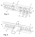
Fig. 1 ; - Fig. 3
- einen vergrößerten Ausschnitt A von
Fig. 2 ; - Fig. 4
- einen vergrößerten Ausschnitt B von
Fig. 2 ; - Fig. 5
- eine erste Konsole in einer perspektivischen Ansicht;
- Fig. 6
- eine zweite Konsole in einer perspektivischen Ansicht;
- Fig. 7
- das Nutzfahrzeug gemäß
Fig. 1 mit fertig montiertem Aufbau.
- Fig. 1
- a commercial vehicle with already mounted subframe, but without structure in a perspective view from behind;
- Fig. 2
- a subframe for mounting a structure on the vehicle according to
Fig. 1 ; - Fig. 3
- an enlarged section A of
Fig. 2 ; - Fig. 4
- an enlarged section B of
Fig. 2 ; - Fig. 5
- a first console in a perspective view;
- Fig. 6
- a second console in a perspective view;
- Fig. 7
- the commercial vehicle according to
Fig. 1 with fully assembled body.
Bei dem in
Im sich an die Führerkabine 5 anschließenden rückwärtigen Bereich des Nutzfahrzeugs 1 ist im Auslieferungszustand, in dem das Nutzfahrzeug 1 das Werk des Nutzfahrzeugherstellers verlässt, über diesem Teil des Chassis 2 ein Freiraum 6 für die Montage eines kofferartigen Aufbaus 7 vorgesehen, der einen Laderaum für mit dem Nutzfahrzeug 1 zu transportierendes Gut umgrenzt.In the subsequent to the
Im Auslieferungszustand weist das Nutzfahrzeug 1 keine Besonderheiten auf, sondern entspricht dem Standard des jeweiligen Herstellers.In the delivery state, the
Das Chassis 2 weist zwei sich in Längsrichtung L des Nutzfahrzeugs 1 erstreckende, als Stahlprofile geformte Langträger 8,9 auf, die parallel zueinander ausgerichtet und durch Querträger 10 miteinander verbunden sind. Auch der übrige Aufbau des Chassis 2 entspricht der üblichen Standardbauweise des jeweiligen Herstellers.The
Für die Montage des Kofferaufbaus 7 ist auf den Langträgern 8,9 ein Hilfsrahmen 11 montiert.For the assembly of the
Der Hilfsrahmen 11 ist durch zwei Hilfslangträger 12,13 und zwei die Hilfslangträger 12,13 parallel zueinander ausgerichtet und auf Abstand haltende Hilfsquerträger 14,15 gebildet. Auf die Hilfsquerträger 14,15 kann gegebenenfalls auch verzichtet werden, wenn die Tragfähigkeit und Steifigkeit der Hilfslangträger 12,13 alleine für die Abstützung des Aufbaus A ausreicht. In diesem Fall besteht der Hilfsrahmen 11 nur aus den Hilfslangträgern 11,12, die bei der Montage als separate Bauteile gehandhabt werden.The
Die quer zur Längserstreckung L und parallel zum Grund, auf dem das Nutzfahrzeug 1 steht, gemessene Breite BH des Hilfsrahmens 11 ist breiter als die zwischen den Außenkanten der Hilfslangträger 12,13 gemessene Breite BC, jedoch kleiner als die der gesetzlich maximal zulässigen Breite entsprechenden Breite BA des Aufbaus 7. Beim hier gezeigten Beispiel ist die Breite BH des Hilfsrahmens 11 zusätzlich so bemessen, dass der Hilfsrahmen 11 zwischen die Antriebsräder R des Nutzfahrzeugs 1 passt.The width BH of the
Die Hilfslangträger 12,13 sind jeweils aus zwei Hilfslangträgerteilstücken 12a,12b und 13a,13b zusammengesetzt. Diese Hilfslangträgerteilstücke 12a,12b sind dabei jeweils aus unterschiedlichen Gruppen von Hilfslangträgerteilstücken ausgewählt worden, die im Betrieb, der die Montage des Aufbaus 7 auf dem Nutzfahrzeug 1 vornimmt, oder beim Hersteller des Aufbaus 7 bevorratet werden. Jedes Hilfslangträgerteilstück einer bestimmten Länge ist dabei jeweils zu einer Gruppe zusammengefasst. So werden beispielsweise sechs Gruppen von unterschiedlich langen, im Übrigen aber identisch geformten Hilfslangträgerteilstücken bereitgehalten. Die Längen der Hilfslangträgerteilstücke der einzelnen Gruppen sind dabei so aufeinander abgestimmt, dass durch Kombination von jeweils zwei oder mehr Hilfslangträgerteilstücken, die einer der Gruppen oder mehreren unterschiedlichen Gruppen entnommenen und miteinander zu jeweils einem Hilfslangträger 12,13 miteinander kombiniert werden, die Gesamtlänge LH der dem jeweiligen Hilfsrahmen 11 zugeordneten Hilfslangträger 12,13 an die auf dem jeweiligen Nutzfahrzeug 1 für die Montage des Aufbaus 7 zur Verfügung stehende Länge LC und die Länge LA des Aufbaus 7 angepasst werden können. Auf diese Weise sind für den Hilfslangträger 12,13 beispielsweise aus der zweiten Gruppe die Hilfslangträgerteilstücke 12a,13a mit einer Länge LH' und aus der vierten Gruppe von Hilfslangträgerteilstücken mit einer Länge LH", welche kürzer ist als die Länge LH', die Hilfslangträgerteilstücke 12b,13b entnommen worden, so dass ein Langträger 12,13 mit der geforderten Gesamtlänge LH = LH' + LH" erhalten wird.The auxiliary
Die Hilfslangträgerteilstücke 12a,12b,13a,13b sind jeweils als U-Profile aus einem Blech geformt. Zur Gewichtsminimierung sind dabei in einen zentralen Bereich ihres Basisabschnitts 16 in regelmäßigen Abständen Öffnungen eingeformt. Zusätzlich weisen über die gesamte zur Verfügung stehende Länge an den jeweiligen oberen Schenkelabschnitt 17 bzw. unteren Schenkelabschnitt 18 angrenzenden Randbereiche des Basisabschnitts 16 der Hilfslangträgerteilstücke 12a - 13b jeweils eine Reihe in gleichmäßigen Abständen angeordnete kreisrunde Durchgangsöffnungen 19 auf.The auxiliary
Um eine einwandfreie Ausrichtung der Hilfslangträgerteilstücke 12a,12b und 13a,13b aneinander zu erleichtern und um den Kraftfluss im Bereich der Fügezonen F1,F2, in der die einander zugeordneten Hilfslangträgerteilstücke 12a,12b und 13a,13b aufeinanderstoßen, zu optimieren, sind die Hilfslangträgerteilstücke 12a-13b im Bereich ihres Basisabschnitts 16 an ihren Enden über ihre Höhe HT zu Anschrägungen 20,21 angeschrägt. Dabei sind die Anschrägungen 20,21 spiegelsymmetrisch zur auf die Längserstreckung L bezogenen Mitte des jeweiligen Hilfslangträgerteilstücks 12a-13b ausgerichtet, so dass jeweils ein Schenkelabschnitt 17 der Hilfslangträgerteilstücke 12a-13b kürzer als ihr anderer Schenkelabschnitt 18 ist. Im Bereich des Übergangs vom Basisabschnitt 16 zu den Schenkelabschnitten 17,18 geht die Anschrägung 20,21 jeweils in einen Absatz 22,23 über, dessen stirnseitige Anlagefläche rechtwinklig zum jeweiligen Schenkelabschnitt 17,18 ausgerichtet ist.In order to facilitate proper alignment of the auxiliary
Für den Zusammenbau der Hilfslangträger 12,13 werden die Hilfslangträgerteilstücke 12a,12b bzw. 13a,13b dementsprechend mit ihren einander zugeordneten Enden so auf Stoß gefügt, dass bei dem einen Hilfslangträgerteilstück 12a,13a der längere Schenkelabschnitt 18 oben liegt, wogegen das jeweils andere Hilfslangträgerteilstück 12b,13b so ausgerichtet wird, dass der kürzere Schenkelabschnitt 17 oben liegt. Gleichzeitig werden die Hilfslangträger 12,13 so ausgerichtet, dass ihre Schenkelabschnitte 17,18 zueinander zeigen, ihre Basisabschnitte 16 also jeweils der Außenseite des Hilfslangträgers 11 zugewandt sind.For the assembly of the auxiliary
Die Fügezone F1,F2 zwischen den Hilfslangträgerteilstücken 12a,12b und 13a,13b wird dann an den den Hilfsquerträger 14,15 zugeordneten Innenseiten ihrer Basisabschnitte 16 mit jeweils einer Verbindungslasche 24 überbrückt, die beispielsweise durch konventionelle, durch die Öffnungen 19 geführte Schraub- oder Rändelbolzverbindungen 26 kraft- und formschlüssig miteinander verbunden.The joining zone F1, F2 between the auxiliary
Beim hier beschriebenen Ausführungsbeispiel erstreckt sich zwischen den einander zugeordneten und gegenüberliegend zueinander in den Fügezonen F1,F2 angeordneten Verbindungslaschen 24 der eine Hilfsquerträger 14. Es ist jedoch selbstverständlich möglich, die Hilfsquerträger 14,15 unabhängig von der Verbindung der Hilfslangträgerteilstücke 12a-13b unter Nutzung der dazu vorgesehenen Durchgangsöffnungen 19 an den Hilfslangträgern 12,13 zu befestigen, wie dies in
Die Abstützung des Hilfsrahmens 11 auf dem Chassis 2 erfolgt über aus Blechzuschnitten geformte Konsolen 27,28.The support of the
Die jeweils schuhartig geformten Konsolen 27,28 weisen einen Befestigungsabschnitt 29 und einen dazu rechtwinklig ausgerichteten Stützabschnitt 30 auf. Der Befestigungsabschnitt 29 besitzt an seiner dem Stützabschnitt 30 zugeordneten Seite eine Anlagefläche 31 für die Außenfläche 16a des Basisabschnitts 16 des jeweils zugeordneten Hilfslangträgers 12,13, wogegen der Stützabschnitt 30 an seiner vom Befestigungsabschnitt 29 abgewandten Unterseite eine Stützfläche 32 aufweist, die rechtwinklig in Bezug auf die Anlagefläche 31 ausgerichtet ist und zum Aufsetzen auf die Oberseite 33 der Langträger 8,9 des Chassis 2 vorgesehen ist. In die Anlageflächen 31 der Konsolen 27,28 sind übereinander mit Abstand zueinander angeordnete schlitzförmige und parallel zur Stützfläche 32 sich erstreckende Durchgangsöffnungen 34,35 in die betreffende Wand des Befestigungsabschnitts eingeformt. Der Abstand der Durchgangsöffnungen 34,35 entspricht dabei dem Abstand der Reihen von Durchgangsöffnungen 19 in den Basisabschnitten 16 der Hilfslangträgerteilstücke 12a-13b. Die Konsolen 27 besitzen jeweils ein Paar von in dieser Weise angeordneten Durchgangsöffnungen 34,35, wogegen bei den Konsolen 28, die etwa doppelt so breit sind wie die Konsolen 27 jeweils zwei paare von Durchgangsöffnungen 34,35 in die Anlagefläche 31 des Befestigungsabschnitts 29 eingeformt sind.The respective shoe-
In den frei über die Anlagefläche 31 hinausstehenden Bereich der Stützfläche 32 des Stützabschnitts 30 ist ebenfalls jeweils mindestens eine in Längsrichtung des Stützabschnitts 30 beabstandete Durchgangsöffnung 36,37 in die jeweilige Wand des Stützabschnitts 30 eingeformt. Der Stützabschnitt 30 der Konsolen 27 weist dabei zwei entsprechend angeordnete Durchgangsöffnungen 36,37 auf, wogegen beim Stützabschnitt 30 der Konsolen 28 nur eine Durchgangsöffnung 36 vorgesehen ist.In the freely projecting beyond the
Die Länge LS des Stützabschnitts 30 und die Lage seiner Durchgangsöffnungen 36,37 sowie die Höhe HB des Befestigungsabschnitts 29 und die Lage seiner Durchgangsöffnungen 34,35 sind dabei so gewählt, dass die Stützabschnitte 30 der Konsolen 27,28 sicher auf der Oberseite 33 der Langträger 8,9 sitzen und andererseits der Hilfsrahmen 11 mit der Außenseite 16a seiner jeweiligen Hilfslangträger 12,13 an der Anlagefläche 31 des Befestigungsabschnitts 29 anliegen. Die Konsolen 27,28 überbrücken auf diese Weise die Breitendifferenz, die zwischen der im Bereich von dessen Längsträgern 8,9 vorhandenen Breite BC des Chassis 2 und der Breite BH des Hilfsrahmens 11 vorhanden ist, und halten den Hilfslangträger 12,13 gleichzeitig so hoch über den Langträgern 8,9, dass seine Oberkante in einer vorgeschriebenen Sollhöhe HSoll über dem ebenen Untergrund U, auf dem das Nutzfahrzeug 1 steht, gehalten ist und bei fertigem Nutzfahrzeug (
Die Konsolen 27,28 sind jeweils aus unterschiedlichen Gruppen von Konsolen ausgewählt worden, die, wie die Hilfslangträgerteilstücke 12a-13b, im Betrieb, der die Montage des Aufbaus 7 auf dem Nutzfahrzeug 1 vornimmt, oder beim Hersteller des Aufbaus 7 bevorratet werden. Die jeweils zu einer der Gruppen zusammengefassten Konsolen unterscheiden sich dabei von den Konsolen der jeweils anderen Gruppen durch die Länge LS ihrer Stützabschnitte 30 und/oder die Höhe HB ihrer Befestigungsabschnitte 29. Ein anderes Unterscheidungskriterium kann die für die Abstützung effektiv nutzbare Länge LS der Stützabschnitte 30 wesentliche Position der Durchgangsöffnungen 36,37 oder die zum Befestigen des jeweils zugeordneten Hilfslangträgers 12,13 effektiv nutzbare Höhe bestimmende Position der schlitzförmigen Durchgangsöffnungen 34,35 in der Anlagefläche 31 sein. So werden beispielsweise zehn Gruppen von unterschiedlich dimensionierten, im Übrigen aber identisch geformten Konsolen bereitgehalten.The
Die Abmessungen der Konsolen der einzelnen Gruppen sind so abgestimmt, dass durch Auswahl von Konsolen aus einer bestimmten Gruppe die beim jeweiligen Nutzfahrzeug 1, auf dem der Aufbau 7 montiert werden soll, bestehende Höhendifferenz zwischen der Isthöhe Hist der Oberkante des Chassis 2 in dessen für die Befestigung der Konsolen vorgesehenen Bereichen (hier die Oberseite 33 der Langträger 8,9) und einer für die Position des Hilfsrahmens 11 vorgesehenen Sollhöhe Hsoll, überbrückt werden kann. Gleichzeitig sind die Abmessungen der bereitstehenden Konsolen so bestimmt, dass die Breitendifferenz, die zwischen der Breite BH des Hilfsrahmens 11 und der Breite BC im Bereich der Langträger 8,9 des Chassis 2 besteht, über die Stützabschnitte 30 der jeweils ausgewählten Konsolen überbrückt werden kann. Die zu den Gruppen zusammengefassten Konsolen sind dabei so bemessen, dass zu jedem gängigen Fahrzeugtyp und zu jedem zugeordneten Hilfsrahmen 11 oder Aufbau 7 mindestens eine Gruppe von passenden Konsolen zur Verfügung steht.The dimensions of the consoles of the individual groups are tuned so that by selecting consoles from a particular group in the respective
Zur Montage des Aufbaus 7 auf dem Nutzfahrzeug 1 werden also die Konsolen 27,28 in der voranstehend beschriebenen Weise aus den bereitstehenden Gruppen von Konsolen ausgewählt.For mounting the
Anschließend werden die Konsolen 27,28 mit ihren Befestigungsabschnitten 29 auf der Oberseite 33 der zugeordneten Langträger 8,9 an dort eingebrachten Durchgangsöffnungen mittels geeigneter Schrauben- oder Rändelbolzverbindungen befestigt. Dabei wird jeweils einer der breiteren Konsolen 28 am der Fahrerkabine 5 zugeordneten Bereich angeordnet, um die dort auftretenden höheren Lasten sicher aufnehmen zu können. Beispielsweise vier der schmaleren Konsolen 27 werden pro Langträger 8,9 in gleichmäßigen Abständen über die zur Verfügung stehende Länge verteilt angeordnet.Subsequently, the
Daraufhin wird der Hilfsrahmen 11 zwischen die Befestigungsabschnitte 30 der Konsolen 27,28 gesetzt und ebenfalls durch Schraub- oder Rändelbolzverbindungen mit den Konsolen 27,28 verbunden. Umfasst der Hilfsrahmen 11 keine Hilfsquerträger 14,15, besteht der Hilfsrahmen 11 also nur aus den Hilfslangträgern 12,13, so werden die Hilfslangträger 12,13 in zwei nacheinander absolvierten Arbeitsschritten an die Befestigungsabschnitte 29 der jeweils zugeordneten Konsolen 27,28 gesetzt und dort befestigt.Then the
Unabhängig, ob sie als Teil des hier in den Figuren gezeigten Hilfsrahmens 11 über die Hilfsquerträger 14,15 miteinander verbunden sind oder ob sie, bei Verzicht auf die Hilfsquerträger 14,15 unabhängig voneinander an die Befestigungsabschitte 29 der Konsolen 27,28 angesetzt werden, erfolgt die Verbindung der jeweiligen Hilfslangträger 12,13 über die zur Deckung gebrachten Öffnungen 19 und 34,35, wobei durch die Schlitzform der Durchgangsöffnungen 34,35 ein Toleranzausgleich ermöglicht ist.Regardless of whether they are connected to each other as part of the subframe shown here in the figures 11 on the
Die Höhe der Durchgangsöffnungen 34,35 über dem Stützabschnitt 30 der Konsolen 27,28 ist dabei unter Berücksichtigung der Höhe des Basisabschnitts 16 der Hilfslangträgerteilstücke 12,13 so bemessen, dass der Hilfsrahmen 11 mit Abstand zur Oberkante der Stützabschnitte 30 an den Konsolen 27,28 gehalten ist. Auf diese Weise wird verhindert, dass Höhentoleranzen die Montage des Hilfsrahmens 11 an den Konsolen 27,28 behindern.The height of the
Nachdem der Hilfsrahmen 11 montiert ist, wird auf ihm der Aufbau 7 in der aus dem Stand der Technik bekannten Weise errichtet.After the
- 11
- Nutzfahrzeugcommercial vehicle
- 22
- Chassischassis
- 33
- Antriebsachsedrive axle
- 44
- gelenkte Achsesteered axle
- 55
- Führerkabinecab
- 66
- Freiraumfree space
- 77
- kofferartiger Aufbaucase-like construction
- 8,98.9
-
Langträger des Chassis 2Long carrier of the
chassis 2 - 1010
-
Querträger des Chassis 2Cross member of the
chassis 2 - 1111
- Hilfsrahmensubframe
- 12,1312.13
- HilfslangträgerAuxiliary longitudinal carrier
- 14,1514.15
- HilfsquerträgerAuxiliary crossbeam
- 12a,12b12a, 12b
- HilfslangträgerteilstückeAuxiliary longitudinal carrier sections
- 13a,13b13a, 13b
- HilfslangträgerteilstückeAuxiliary longitudinal carrier sections
- 1616
-
jeweiliger Basisabschnitt der Hilfslangträgerteilstücke 12a-13brespective base portion of the auxiliary
longitudinal beam sections 12a-13b - 16a16a
-
Außenfläche des Basisabschnitts 16 der Hilfslangträger 12,13Outer surface of the
base portion 16 of the auxiliarylongitudinal beams - 17,1817.18
-
jeweilige Schenkelabschnitte der Hilfslangträgerteilstücke 12a-13brespective leg portions of the auxiliary
longitudinal beam sections 12a-13b - 1919
- DurchgangsöffnungenThrough openings
- 20,2120.21
- Anschrägungenbevels
- 22,2322.23
- Absätzeparagraphs
- 2424
- Verbindungslascheconnecting strap
- 2626
- RändelbolzverbindungenRändelbolzverbindungen
- 27,2827.28
- Konsolenconsoles
- 2929
- Befestigungsabschnittattachment section
- 3030
- Stützabschnittsupport section
- 3131
- Anlageflächecontact surface
- 3232
- Stützfläche zur Anlage an die Oberseite 33 der Langträger 8,9Support surface for engagement with the top 33 of the long beam 8.9
- 3333
-
jeweilige Oberseite der Langträger 8,9respective upper side of the
longitudinal beams 8,9 - 34,3534.35
- schlitzförmig Durchgangsöffnungenslit-shaped through holes
- 36,3736.37
- Durchgangsöffnungen im Stützabschnitt 30Through holes in the support portion 30th
- BHbra
-
Breite des Hilfsrahmens 11Width of the
subframe 11 - BCBC
-
Breite des Chassis 2 im Bereich der Langträger 8,9Width of the
chassis 2 in the area of the long beam 8.9 - BABA
-
Breite des Aufbaus 7Width of
construction 7 - F1,F2F1, F2
- Fügezonenjoining zones
- HBHB
-
Höhe des Befestigungsabschnitts 29Height of the
attachment portion 29 - HsollHsetpoint
-
Sollhöhe der Oberkante des Hilfsrahmens 11Target height of the upper edge of the
subframe 11 - Histhist
-
Isthöhe der Oberkante des Chassis 2Actual height of the upper edge of the
chassis 2 - LL
-
Längsrichtung des Nutzfahrzeugs 1Longitudinal direction of the
commercial vehicle 1 - LHLH
-
Gesamtlänge des jeweiligen Hilfslangträgers 12,13Total length of the respective auxiliary
longitudinal carrier - LCLC
-
für die Montage des Aufbaus 7 zur Verfügung stehende Längefor the assembly of the
body 7 available length - LALA
-
Länge des Aufbaus 7Length of
body 7 - LH'LH '
-
Länge der Hilfslangträgerteilstücke 12a,13aLength of the auxiliary
longitudinal support sections - LH"LH "
-
Länge der Hilfslangträgerteilstücke 12b,13bLength of the auxiliary
longitudinal support sections - LSLS
-
Länge des Stützabschnitts 30Length of the
support section 30 - RR
- Antriebsräderdrive wheels
- UU
- ebener Untergrundlevel surface
Claims (15)
gekennzeichnet, dass der Aufbau (7) von einem Hilfsrahmen (11) getragen ist, der auf dem Chassis (2) über einzelne Konsolen (27,28) abgestützt ist, die den Hilfsrahmen (11) bezogen auf einen ebenen Untergrund (U), auf dem das Nutzfahrzeug (1) steht, in einer Sollhöhe (Hsoll) halten, die höher ist als die auf den ebenen Untergrund (U) bezogene Höhe (Hist) der Oberkante des Chassis (2) in dem Bereich (6), in dem der Aufbau (7) montiert ist.Commercial vehicle is mounted with a chassis (2) on which at least one axis (3) with wheels (R) of the utility vehicle (1), and having a structure (7) which is erected on the chassis (2), characterized
characterized in that the structure (7) is supported by a subframe (11) supported on the chassis (2) by individual brackets (27, 28) which support the subframe (11) with respect to a flat ground (U), on which the commercial vehicle (1) stands, at a desired height (Hsoll), which is higher than the reference to the flat ground (U) height (Hist) of the upper edge of the chassis (2) in the region (6), in the the structure (7) is mounted.
dass das Chassis (2) zwei Langträger (8,9) umfasst, auf denen die den Hilfsrahmen (11) stützenden Konsolen (27,28) stehen.Commercial vehicle according to claim 1, characterized
in that the chassis (2) comprises two longitudinal beams (8, 9) on which are brackets (27, 28) supporting the subframe (11).
dass die Hilfslangträgerteilstücke (12a,12b,13a,13b) mittels Verbindungslaschen (24) miteinander verbunden sind.Commercial vehicle according to claim 3, characterized
in that the auxiliary longitudinal support sections (12a, 12b, 13a, 13b) are connected to one another by means of connecting straps (24).
dass die Verbindungslaschen (24) ausschließlich form- oder kraftschlüssig mit den Hilfslangträgerteilstücken (12a-13b) verbunden sind.Commercial vehicle according to claim 4, characterized in that
in that the connecting straps (24) are connected exclusively with the auxiliary longitudinal support sections (12a-13b) in a form-locking or force-locking manner.
gekennzeichnet, dass die Hilfslangträgerteilstücke (12a-13b) an ihren Enden jeweils eine in Höhen- und Längsrichtung des Hilfslangträgerteilstücks (12a-13b) angeschrägte Anschrägung (20,21) aufweisen.Commercial vehicle according to one of claims 3 - 5, characterized
characterized in that the Hilfslangträgerteilstücke (12a-13b) at their ends in each case in the height and length direction of the Hilfslangträgerteil (12a-13b) beveled bevel (20,21).
dass die an beiden Enden der Längsträger jeweils vorgesehenen Anschrägungen (20,21) bezogen auf die Mitte des Hilfslangträgerteilstücks (12a-13b) spiegelsymmetrisch geformt sind.Commercial vehicle according to claim 6, characterized
in that the chamfers (20, 21) respectively provided at both ends of the longitudinal members are mirror-symmetrically shaped relative to the center of the auxiliary longitudinal carrier section (12a-13b).
gekennzeichnet, dass die Konsolen (27,28) schuhförmig mit einem Befestigungsabschnitt (29) und einem rechtwinklig zum Befestigungsabschnitt (29) angeordneten Stützabschnitt (30) ausgebildet sind, dass der Hilfsrahmen (11) an einer dem Stützabschnitt (30) zugewandten Anlagefläche (31) des Befestigungsabschnitts (29) anliegt und dass der Stützabschnitt (30) mit einer vom Befestigungsabschnitt (29) abgewandten Stützfläche (32) am zugeordneten Bauteil (8,9) des Chassis (2) abgestützt ist.Commercial vehicle according to one of the preceding claims, characterized
in that the brackets (27, 28) are configured in the form of a shoe with a fastening section (29) and a support section (30) arranged at right angles to the fastening section (29) such that the auxiliary frame (11) adjoins a contact surface (31) facing the support section (30) ) of the attachment portion (29) and that the support portion (30) with a mounting portion (29) facing away from the support surface (32) on the associated component (8,9) of the chassis (2) is supported.
dass die Konsolen (27,28) ausschließlich form- oder kraftschlüssig mit dem jeweils zugeordneten Hilfslangträger (12,13) und dem Chassis (2) verbunden sind.Commercial vehicle according to claim 8, characterized
in that the brackets (27, 28) are connected only in a positive or non-positive manner to the respective associated auxiliary longitudinal carrier (12, 13) and to the chassis (2).
oder
or
gekennzeichnet, dass derHilfsrahmen(11)alsBausatz bereitgestellt wird, der mindestens zwei Gruppen von Hilfslangträgerteilstücken (12a,13a;12b,13b) umfasst, wobei sich die Gruppen von Hilfslangträgerteilstücken (12a,13a;12b,13b) durch die Länge (LH',LH") der ihnen zugeordneten Hilfslangträgerteilstücke (12a,13a;12b,13b) unterscheiden, die Hilfslangträgerteilstücke (12a,13a;12b,13b) der Gruppen im Übrigen jedoch identisch geformt sind, dass das aus den Gruppen von Hilfslangträgerteilstücken (12a,13a;12b,13b) unter Berücksichtigung einer Solllänge (LH) des Hilfsrahmens (11) jeweils Hilfslangträgerteilstücke (12a,13a;12b,13b) unterschiedlicher Länge (LH',LH") derart ausgewählt werden, dass die Gesamtlänge (LH) von mindestens zwei aus den ausgewählten Hilfslangträgerteilstücken (12a,12b;13a,13b) zusammengesetzten Hilfslangträgern (12,13) jeweils der Solllänge (LH) des Hilfsrahmens (11) entspricht, und dass unter Verwendung der aus den Hilfslangträgerteilstücken (12a,13a;12b,13b) gebildeten Hilfslangträgern (12,13) der Hilfsrahmen (11) montiert wird.A method according to claim 12 or 13, characterized
characterized in that the auxiliary frame (11) is provided as a kit comprising at least two sets of auxiliary longitudinal support sections (12a, 13a; 12b, 13b), the groups of auxiliary longitudinal support sections (12a, 13a; 12b, 13b) being defined by the length (LH ', Incidentally, however, the auxiliary longitudinal support sections (12a, 13a; 12b, 13b) of the groups are otherwise identically shaped such that the one of the groups of auxiliary longitudinal support sections (12a, 13a; 12b, 13b) taking into account a desired length (LH) of the auxiliary frame (11), respectively auxiliary longitudinal support sections (12a, 13a, 12b, 13b) different length (LH ', LH ") are selected such that the total length (LH) of at least two of the selected auxiliary longitudinal carrier sections (12a, 12b, 13a, 13b) composed auxiliary longitudinal beams (12,13) each of the desired length (LH) of the subframe (11), and that by using the auxiliary longitudinal beams (12, 13) formed of the auxiliary longitudinal beam sections (12a, 13a, 12b, 13b), the subframe (11) is mounted.
gekennzeichnet, dass die Konsolen (27,28) mit dem Chassis (2), die Konsolen (27,28) mit dem Hilfsrahmen (11), der Hilfsrahmen (11) mit dem Aufbau (7) und die Bauteile (12,13,14,15,24) des Hilfsrahmens (11) untereinander jeweils ausschließlich form- oder kraftschlüssig miteinander verbunden werden.Method according to one of claims 12-14, characterized
g characterized in that the brackets (27,28) to the chassis (2), the brackets (27,28) with the subframe (11), the subframe (11) with the structure (7) and the components (12,13 , 14,15,24) of the subframe (11) are mutually interconnected exclusively with positive or non-positive.
Priority Applications (1)
| Application Number | Priority Date | Filing Date | Title |
|---|---|---|---|
| EP16189673.3A EP3296186A1 (en) | 2016-09-20 | 2016-09-20 | Commercial vehicle with a structure and method for mounting a structure on a commercial vehicle |
Applications Claiming Priority (1)
| Application Number | Priority Date | Filing Date | Title |
|---|---|---|---|
| EP16189673.3A EP3296186A1 (en) | 2016-09-20 | 2016-09-20 | Commercial vehicle with a structure and method for mounting a structure on a commercial vehicle |
Publications (1)
| Publication Number | Publication Date |
|---|---|
| EP3296186A1 true EP3296186A1 (en) | 2018-03-21 |
Family
ID=56958851
Family Applications (1)
| Application Number | Title | Priority Date | Filing Date |
|---|---|---|---|
| EP16189673.3A Withdrawn EP3296186A1 (en) | 2016-09-20 | 2016-09-20 | Commercial vehicle with a structure and method for mounting a structure on a commercial vehicle |
Country Status (1)
| Country | Link |
|---|---|
| EP (1) | EP3296186A1 (en) |
Cited By (4)
| Publication number | Priority date | Publication date | Assignee | Title |
|---|---|---|---|---|
| CN109278867A (en) * | 2018-11-15 | 2019-01-29 | 陕西宏象房车科技发展有限公司 | Adjustable length pulls caravan chassis |
| CN111186493A (en) * | 2020-03-03 | 2020-05-22 | 天津中科先进技术研究院有限公司 | Light high-strength composite material truck auxiliary frame transverse and longitudinal beam structure |
| EP3680150A1 (en) * | 2019-01-09 | 2020-07-15 | C.R.F. Società Consortile per Azioni | Vehicle having a frame provided with a supporting structure for auxiliary units, in particular gas tanks or electric batteries |
| WO2022262631A1 (en) * | 2021-06-18 | 2022-12-22 | 杭州海康机器人股份有限公司 | Chassis structure and transport vehicle |
Citations (8)
| Publication number | Priority date | Publication date | Assignee | Title |
|---|---|---|---|---|
| DE10040018A1 (en) * | 1999-09-07 | 2001-03-08 | Henschel Engineering Sa Nv | Fastening system for load platform on vehicle substructure consists of longitudinal struts and connection parts connected via bolts and nuts, on platform and substructure |
| EP1190899A1 (en) * | 2000-09-26 | 2002-03-27 | Van den Top, Hendrik | Multifunctional vehicle, method and auxiliary chassis therefor |
| DE10248102A1 (en) | 2001-10-15 | 2003-07-24 | Schmitz Cargobull Ag | Joint connection for metal elements has fitting shank section of screw in rubbing contact with inside of holes formed in metal elements to be joined and has fine flutes and ribs distributed over periphery |
| EP1445178A1 (en) * | 2003-02-06 | 2004-08-11 | Aghito Sistemi S.r.l. | Floor of a vehicle for load carrying |
| US20060021541A1 (en) * | 2004-08-02 | 2006-02-02 | Oshkosh Truck Corporation | Universal mounting system |
| FR2914242A1 (en) * | 2007-03-30 | 2008-10-03 | Frejalines Sa | Trailer e.g. container load type trailer, for transporting container type loads, has module formed with cross pieces of container or frameworks, and base structure with flange including interface common to cross pieces and frameworks |
| EP2524856B1 (en) | 2011-05-20 | 2014-07-02 | Schmitz Cargobull AG | Superstructure for a commercial vehicle |
| WO2015082803A1 (en) * | 2013-12-06 | 2015-06-11 | Nexter Systems | Shielded vehicle connected to a chassis |
-
2016
- 2016-09-20 EP EP16189673.3A patent/EP3296186A1/en not_active Withdrawn
Patent Citations (8)
| Publication number | Priority date | Publication date | Assignee | Title |
|---|---|---|---|---|
| DE10040018A1 (en) * | 1999-09-07 | 2001-03-08 | Henschel Engineering Sa Nv | Fastening system for load platform on vehicle substructure consists of longitudinal struts and connection parts connected via bolts and nuts, on platform and substructure |
| EP1190899A1 (en) * | 2000-09-26 | 2002-03-27 | Van den Top, Hendrik | Multifunctional vehicle, method and auxiliary chassis therefor |
| DE10248102A1 (en) | 2001-10-15 | 2003-07-24 | Schmitz Cargobull Ag | Joint connection for metal elements has fitting shank section of screw in rubbing contact with inside of holes formed in metal elements to be joined and has fine flutes and ribs distributed over periphery |
| EP1445178A1 (en) * | 2003-02-06 | 2004-08-11 | Aghito Sistemi S.r.l. | Floor of a vehicle for load carrying |
| US20060021541A1 (en) * | 2004-08-02 | 2006-02-02 | Oshkosh Truck Corporation | Universal mounting system |
| FR2914242A1 (en) * | 2007-03-30 | 2008-10-03 | Frejalines Sa | Trailer e.g. container load type trailer, for transporting container type loads, has module formed with cross pieces of container or frameworks, and base structure with flange including interface common to cross pieces and frameworks |
| EP2524856B1 (en) | 2011-05-20 | 2014-07-02 | Schmitz Cargobull AG | Superstructure for a commercial vehicle |
| WO2015082803A1 (en) * | 2013-12-06 | 2015-06-11 | Nexter Systems | Shielded vehicle connected to a chassis |
Cited By (5)
| Publication number | Priority date | Publication date | Assignee | Title |
|---|---|---|---|---|
| CN109278867A (en) * | 2018-11-15 | 2019-01-29 | 陕西宏象房车科技发展有限公司 | Adjustable length pulls caravan chassis |
| EP3680150A1 (en) * | 2019-01-09 | 2020-07-15 | C.R.F. Società Consortile per Azioni | Vehicle having a frame provided with a supporting structure for auxiliary units, in particular gas tanks or electric batteries |
| WO2020144498A1 (en) | 2019-01-09 | 2020-07-16 | C.R.F. Società Consortile Per Azioni | Vehicle having a frame provided with a supporting structure for auxiliary units, in particular gas tanks or electric batteries |
| CN111186493A (en) * | 2020-03-03 | 2020-05-22 | 天津中科先进技术研究院有限公司 | Light high-strength composite material truck auxiliary frame transverse and longitudinal beam structure |
| WO2022262631A1 (en) * | 2021-06-18 | 2022-12-22 | 杭州海康机器人股份有限公司 | Chassis structure and transport vehicle |
Similar Documents
| Publication | Publication Date | Title |
|---|---|---|
| DE102005048379B4 (en) | Storage rack with a variety of shelving units | |
| DE102013020823B3 (en) | Support structure and method for welding a chassis frame longitudinal beam of a rail vehicle | |
| DE102010029563B4 (en) | channel storage | |
| EP3296186A1 (en) | Commercial vehicle with a structure and method for mounting a structure on a commercial vehicle | |
| WO2014063687A2 (en) | Modular system | |
| DE202005017269U1 (en) | Storage racking has first transporting means which consists of several detachably interconnected modules, the number of which is variable in dependence upon number of rack units | |
| WO2018007204A1 (en) | Motor vehicle | |
| EP1927506B1 (en) | Vehicle frame with cross-members for securing a load and cross-members therefor | |
| DE102014211534B4 (en) | Method for producing vehicle bodies | |
| DE2364849C3 (en) | Floor pan for commercial vehicles | |
| DE102018132257B4 (en) | Front axle support arrangement on an electrically operated motor vehicle | |
| EP2729349B1 (en) | Vehicle and method for mounting a drive assembly | |
| EP0572929A1 (en) | Parking platform | |
| EP3696054B1 (en) | Modular vehicle chassis with rear frame overhang | |
| WO2006037549A1 (en) | Subframe for the chassis frame of a utility vehicle | |
| DE19651627B4 (en) | Substructure structure of a motor vehicle body | |
| DE102009022090A1 (en) | High-bay warehouse and support for a high-bay warehouse and method for producing the support | |
| DE102019124074A1 (en) | Instrument panel support for a motor vehicle | |
| DE102019102687A1 (en) | Vehicle, preferably commercial vehicle, with a lattice frame | |
| DE10200982A1 (en) | Transporter to move pref. motor cars between production stations consists of pre-assembled main frame with locking and support devices to secure car body without wheels | |
| EP2103502A1 (en) | Commercial vehicle with a box body | |
| DE102016007327A1 (en) | Device for storing and / or transporting components | |
| DE102009023333A1 (en) | Frame structure for large-volume vehicle i.e. omnibus, has cross beam units and side member units coupled with steering wheels of front wheel suspensions, such that action lines of forces are formed in beam levels or side member levels | |
| EP0437655B1 (en) | Ladder frame | |
| DE102010016552B4 (en) | Side member for load securing |
Legal Events
| Date | Code | Title | Description |
|---|---|---|---|
| PUAI | Public reference made under article 153(3) epc to a published international application that has entered the european phase |
Free format text: ORIGINAL CODE: 0009012 |
|
| AK | Designated contracting states |
Kind code of ref document: A1 Designated state(s): AL AT BE BG CH CY CZ DE DK EE ES FI FR GB GR HR HU IE IS IT LI LT LU LV MC MK MT NL NO PL PT RO RS SE SI SK SM TR |
|
| AX | Request for extension of the european patent |
Extension state: BA ME |
|
| 17P | Request for examination filed |
Effective date: 20180920 |
|
| RBV | Designated contracting states (corrected) |
Designated state(s): AL AT BE BG CH CY CZ DE DK EE ES FI FR GB GR HR HU IE IS IT LI LT LU LV MC MK MT NL NO PL PT RO RS SE SI SK SM TR |
|
| 17Q | First examination report despatched |
Effective date: 20190715 |
|
| GRAP | Despatch of communication of intention to grant a patent |
Free format text: ORIGINAL CODE: EPIDOSNIGR1 |
|
| INTG | Intention to grant announced |
Effective date: 20200401 |
|
| STAA | Information on the status of an ep patent application or granted ep patent |
Free format text: STATUS: THE APPLICATION IS DEEMED TO BE WITHDRAWN |
|
| 18D | Application deemed to be withdrawn |
Effective date: 20200812 |