EP1445178A1 - Floor of a vehicle for load carrying - Google Patents
Floor of a vehicle for load carrying Download PDFInfo
- Publication number
- EP1445178A1 EP1445178A1 EP03425070A EP03425070A EP1445178A1 EP 1445178 A1 EP1445178 A1 EP 1445178A1 EP 03425070 A EP03425070 A EP 03425070A EP 03425070 A EP03425070 A EP 03425070A EP 1445178 A1 EP1445178 A1 EP 1445178A1
- Authority
- EP
- European Patent Office
- Prior art keywords
- floor
- layer
- board
- main frame
- thickness
- Prior art date
- Legal status (The legal status is an assumption and is not a legal conclusion. Google has not performed a legal analysis and makes no representation as to the accuracy of the status listed.)
- Granted
Links
Images


Classifications
-
- B—PERFORMING OPERATIONS; TRANSPORTING
- B60—VEHICLES IN GENERAL
- B60J—WINDOWS, WINDSCREENS, NON-FIXED ROOFS, DOORS, OR SIMILAR DEVICES FOR VEHICLES; REMOVABLE EXTERNAL PROTECTIVE COVERINGS SPECIALLY ADAPTED FOR VEHICLES
- B60J5/00—Doors
- B60J5/04—Doors arranged at the vehicle sides
- B60J5/0497—Doors arranged at the vehicle sides for load transporting vehicles or public transport, e.g. lorries, trucks, buses
- B60J5/0498—Doors arranged at the vehicle sides for load transporting vehicles or public transport, e.g. lorries, trucks, buses with rigid panels pivoting about a horizontal axis
-
- B—PERFORMING OPERATIONS; TRANSPORTING
- B60—VEHICLES IN GENERAL
- B60P—VEHICLES ADAPTED FOR LOAD TRANSPORTATION OR TO TRANSPORT, TO CARRY, OR TO COMPRISE SPECIAL LOADS OR OBJECTS
- B60P1/00—Vehicles predominantly for transporting loads and modified to facilitate loading, consolidating the load, or unloading
-
- B—PERFORMING OPERATIONS; TRANSPORTING
- B62—LAND VEHICLES FOR TRAVELLING OTHERWISE THAN ON RAILS
- B62D—MOTOR VEHICLES; TRAILERS
- B62D21/00—Understructures, i.e. chassis frame on which a vehicle body may be mounted
- B62D21/12—Understructures, i.e. chassis frame on which a vehicle body may be mounted assembled from readily detachable parts
-
- B—PERFORMING OPERATIONS; TRANSPORTING
- B62—LAND VEHICLES FOR TRAVELLING OTHERWISE THAN ON RAILS
- B62D—MOTOR VEHICLES; TRAILERS
- B62D25/00—Superstructure or monocoque structure sub-units; Parts or details thereof not otherwise provided for
- B62D25/20—Floors or bottom sub-units
- B62D25/2054—Load carrying floors for commercial vehicles
-
- B—PERFORMING OPERATIONS; TRANSPORTING
- B62—LAND VEHICLES FOR TRAVELLING OTHERWISE THAN ON RAILS
- B62D—MOTOR VEHICLES; TRAILERS
- B62D33/00—Superstructures for load-carrying vehicles
- B62D33/02—Platforms; Open load compartments
Definitions
- the present invention relates to a floor of a vehicle for load carrying, for example a commercial vehicle, an industrial vehicle and the like, which comprises a plate-like flat structure mounted on a vehicle main frame.
- the floor is expected to be sufficiently strong to take the weight of its load, both loose and manufactured goods, directly loaded or with proper pallets without yielding, without significant deformations or breakage, over long routes on roads where maintenance condition may be not perfect.
- the underlying problem of this invention is to provide a floor as indicated, having structural and functional features to obviate the above drawback.
- a floor as indicated being characterized in that its plate-like flat structure comprises a board including a number of layers, whereof one having prevalent thickness and cellular matrix, and a framework.
- a floor according to the invention is generally shown with 1.
- the floor 1 is part of a vehicle 2 for load carrying, which, in the example, is a commercial or industrial vehicle, specifically a small truck.
- vehicle 2 is provided with a frame 3 whereon the floor 1 is mounted.
- the floor 1 comprises a plate-like flat structure 4, which has a rectangular outline, with its long sides or edges extending lengthwise and coinciding with the motion direction of the vehicle, and with short sides or edges extending according to a crosswise direction, perpendicularly to said motion direction.
- the plate-like flat structure 4 comprises a board 5 including a number of layers 6, 7, 8.
- the board 5 comprises a middle layer 6, which has prevalent thickness.
- the layer 6 is sandwiched between a top layer 7 and a bottom layer 8, both of limited thickness.
- the middle layer 6 has a thickness "a" selected between 30 and 70 mm. It has cellular matrix. In this example, it has a structure formed by cells 9 alveolar or honeycomb and it is of a synthetic material, e.g. polypropylene.
- the top layer 7 has a thickness "b" selected between 4 and 8 mm, in this example of 6.8 mm.
- the top layer 7 consists of a plurality of wood sheets, e.g. of birch or beech wood, assembled into a plywood sheet 10, and it is sandwiched between a facing layer 11 and a reinforcing layer 12.
- the facing layer 11 is a suitable synthetic material having good antiwear, antislide, waterproof, flame-resistant properties and being washable, e.g. a phenolic resin.
- the reinforcing layer 12 is a metallic or fiber laminate, e.g. Kevlar or glass fiber.
- an undercut 13 is provided, the undercut being a few millimeters deep and a few centimeters wide.
- the bottom layer 8 is of a metal sheet, preferably of light alloy such as aluminum alloy, or of a fibrous material, e.g. glass fiber or Kevlar.
- the thickness "c" of the layer 8 is chosen between 0.2 and 1.2 mm. Lower values are chosen for metallic materials and higher values for synthetic materials. A preferred material is steel and its thickness of 0.4 mm.
- the board 5 is completed with a framework, generally designated with 14.
- the framework 14 comprises rod-like inserts 15 which are transversely embedded in the thickness of layer 6.
- the rod-like inserts 15 are made of metal, e.g. from square box-like sectional stock of aluminum whose side dimension equals the thickness of the layer 6.
- the rod-like inserts 15 could be formed from a synthetic material, with or without reinforcing fibers.
- the inserts 15 are integral with the board layers through proper adhesive, e.g. using a two-part adhesive.
- the top and bottom surfaces of the rod-like inserts are irregular as shown at 15a, e.g. with a sawtooth pattern of score lines.
- the framework 14 further comprises two stringers 16, 17 having a substantially C-shaped cross-section and extending along the longitudinal sides of the board 5.
- the stringers 16 and 17 are preferably made through aluminum extrusions and have a top wing 18, a core 19, and a bottom wing 20. They are applied to the board edges in a with prefixed driving and there adhesively arranged, e.g. using a two-part adhesive.
- the top wing 18 and bottom wing 20 have irregular surfaces as shown at 18a and 20a, respectively, e.g. with sawtooth score lines to enhance the adhesive bond.
- the core 19 is box-like with a bottom extension 19a, also box-like, and a further rod-like extension 19b, jointly giving the extrusion a substantially F-shaped overall cross-section.
- the extension 19a additionally to its stiffening function, is a base for etching various equipping elements as well as a cableway.
- the extension 19b serves a stiffening function and, in addition, carries tarpaulin points of attachment.
- the top wing 18 fits in the undercut 13 so that the top surface of the board is perfectly plane.
- the framework 14 further includes two stringers 21, 22, preferably extruded from aluminum and having the same cross-sectional shape as the stringers 16 and 17, which extend along the transversal sides of the board 5 to which they are fixed as described for the stringers 16 and 17.
- the rod-like inserts 15, like stringers 21 and 22 are cross-members of the vehicle main frame 3, and work as such.
- the stringers 16 and 17 are stringers of the frame 3, and work as such.
- the vehicle main frame 3 results from the combination of the two sleepers 23, 24 and the framework 14.
- the board 5 is secured on the frame sleepers 23 and 24 of the main frame 3 through fixing means 25 which consist of respective spacers 26 and 27, preferably in the form of Z-shaped section stringers whose top and bottom wings 28 and 29 are respectively attached to the floor and to the longitudinal member, by means of screws and adhesive.
- the floor 30 is suitable for load 31 carrying, e.g. a commercial or industrial vehicle, specifically a big truck such as an articulated vehicle, having a main frame 32 on which the floor 30 is mounted.
- the floor 30 comprises a board 33 which is split into a plurality of successive short boards 34 assembled together as segments of the floor board.
- the panels 34 are all identical and set one after another to form the desired floor length.
- a joint 35 is provided between adjacent panels 34 for mutual connection.
- the joint 35 is made of two identical rod-like inserts 36 that fit between two facing ends of the boards or board segments 34 and there held by using a suitable two-part adhesive.
- Each rod-like insert 36 has a box-like section, and has irregular top and bottom surfaces scored with sawtooth score lines 36a for enhanced adhesive bond.
- Each rod-like insert 36 has an inner ribbing 37.
- the inner ribbing 37 has a mortise 38 and an open-ring termination 39.
- the joint 35 further incorporates a listel 40. When the joint 35 operates, the listel 40 engages the mortises 38 one another, much after the style of a classic mortise-and-tenon joint.
- Tying members 41 in the form of threaded bars or screws are engaged in the open-ring terminations 39 to secure the sequenced boards 34 to a common C-shaped stringer, 16 and 17, extending all along each lengthwise edge of the floor board 33.
- the individual panels 34 are secured together into a unitary floor board.
- rod-like inserts 36 and the listel 40 are crossmembers for the vehicle main frame.
- a floor according to the invention was tested statically, by loading a board 4.50 meters long and 2.13 meters wide, being secured on two longitudinal side members bearing on floor stands, and loaded in stages up to 2208 kg/m 2 .
- the board withstood this loading successfully, and only inceptive sag of one longitudinal side member was to be noticed.
- the principal advantage of the load-platform floor of the invention is its uniquely simple construction, the floor board constituting a self-supporting monolithic member that is quick to manufacture and allows shorter lead times while, by virtue of all its parts working in concert, the floor board shows excellent load capacity with both spread and concentrated loads.
- the board could be a modular construction, so that several different sizes can be provided for but a small number of specific parts.
- the invention is susceptible of retrofit, to be carried out as a vehicle is undergoing conversion or a rebuild.
- the floor of this invention may be added raised sides, hoops, and the like, in customized versions.
Abstract
Description
- The present invention relates to a floor of a vehicle for load carrying, for example a commercial vehicle, an industrial vehicle and the like, which comprises a plate-like flat structure mounted on a vehicle main frame.
- As it is known, the floor is expected to be sufficiently strong to take the weight of its load, both loose and manufactured goods, directly loaded or with proper pallets without yielding, without significant deformations or breakage, over long routes on roads where maintenance condition may be not perfect.
- This requirement is currently met by floors having a plate-like flat structure, e.g. of wood, arranged to rest on the vehicle main frame, commonly reticular, metallic frame, such as steel.
- While being advantageous in several respects and performing fairly satisfactorily, such prior floors have a drawback, accepted so far, in that their complicated construction reflects on extended manufacturing times and, as a consequence, long periods for delivering the desired vehicle.
- The underlying problem of this invention is to provide a floor as indicated, having structural and functional features to obviate the above drawback.
- The problem is solved by a floor as indicated being characterized in that its plate-like flat structure comprises a board including a number of layers, whereof one having prevalent thickness and cellular matrix, and a framework.
- Further features and the advantages of the floor according to the invention should become apparent from the following description of an embodiment thereof, given by way of non-limitative example with reference to the accompanying drawings.
-
- Figure 1 is a schematic perspective view of a vehicle incorporating the floor of this invention.
- Figure 2 is a cutaway perspective view, drawn to an enlarged scale, of the floor shown in Figure 1.
- Figure 3 is an exploded perspective view, drawn to an even larger scale, of a detail of the floor shown in Figure 2.
- Figure 4 is a perspective view of a vehicle incorporating a modified version of the floor of this invention.
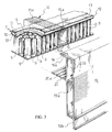
- Figure 5 is a cutaway perspective view, drawn to an enlarged scale, of the floor shown in Figure 4.
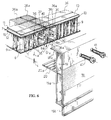
- Figure 6 is an exploded perspective view, drawn to an even larger scale, of a detail of the floor shown in Figure 5.
-
- With reference to the enclosed drawings, a floor according to the invention is generally shown with 1.
- The
floor 1 is part of a vehicle 2 for load carrying, which, in the example, is a commercial or industrial vehicle, specifically a small truck. The vehicle 2 is provided with aframe 3 whereon thefloor 1 is mounted. - The
floor 1 comprises a plate-like flat structure 4, which has a rectangular outline, with its long sides or edges extending lengthwise and coinciding with the motion direction of the vehicle, and with short sides or edges extending according to a crosswise direction, perpendicularly to said motion direction. - The plate-like flat structure 4 comprises a board 5 including a number of
layers middle layer 6, which has prevalent thickness. Thelayer 6 is sandwiched between a top layer 7 and abottom layer 8, both of limited thickness. - The
middle layer 6 has a thickness "a" selected between 30 and 70 mm. It has cellular matrix. In this example, it has a structure formed bycells 9 alveolar or honeycomb and it is of a synthetic material, e.g. polypropylene. - The top layer 7 has a thickness "b" selected between 4 and 8 mm, in this example of 6.8 mm.
- The top layer 7 consists of a plurality of wood sheets, e.g. of birch or beech wood, assembled into a
plywood sheet 10, and it is sandwiched between a facinglayer 11 and a reinforcinglayer 12. The facinglayer 11 is a suitable synthetic material having good antiwear, antislide, waterproof, flame-resistant properties and being washable, e.g. a phenolic resin. The reinforcinglayer 12 is a metallic or fiber laminate, e.g. Kevlar or glass fiber. - At the top layer periphery, i.e. all along the longitudinal and transverse edges of the board, an
undercut 13 is provided, the undercut being a few millimeters deep and a few centimeters wide. - The
bottom layer 8 is of a metal sheet, preferably of light alloy such as aluminum alloy, or of a fibrous material, e.g. glass fiber or Kevlar. The thickness "c" of thelayer 8 is chosen between 0.2 and 1.2 mm. Lower values are chosen for metallic materials and higher values for synthetic materials. A preferred material is steel and its thickness of 0.4 mm. - The board 5 is completed with a framework, generally designated with 14.
- The
framework 14 comprises rod-like inserts 15 which are transversely embedded in the thickness oflayer 6. The rod-like inserts 15 are made of metal, e.g. from square box-like sectional stock of aluminum whose side dimension equals the thickness of thelayer 6. Alternatively, the rod-like inserts 15 could be formed from a synthetic material, with or without reinforcing fibers. Theinserts 15 are integral with the board layers through proper adhesive, e.g. using a two-part adhesive.Preferably, the top and bottom surfaces of the rod-like inserts are irregular as shown at 15a, e.g. with a sawtooth pattern of score lines. - The
framework 14 further comprises twostringers - In particular, the
stringers top wing 18, acore 19, and abottom wing 20. They are applied to the board edges in a with prefixed driving and there adhesively arranged, e.g. using a two-part adhesive. Thetop wing 18 andbottom wing 20 have irregular surfaces as shown at 18a and 20a, respectively, e.g. with sawtooth score lines to enhance the adhesive bond. - The
core 19 is box-like with abottom extension 19a, also box-like, and a further rod-like extension 19b, jointly giving the extrusion a substantially F-shaped overall cross-section. Theextension 19a, additionally to its stiffening function, is a base for etching various equipping elements as well as a cableway. Theextension 19b serves a stiffening function and, in addition, carries tarpaulin points of attachment. - The
top wing 18 fits in the undercut 13 so that the top surface of the board is perfectly plane. - The
framework 14 further includes twostringers stringers stringers - It should be noted that the rod-
like inserts 15, likestringers 21 and 22are cross-members of the vehiclemain frame 3, and work as such. Similarly, thestringers frame 3, and work as such. In other words, the vehiclemain frame 3 results from the combination of the twosleepers framework 14. - The board 5 is secured on the
frame sleepers main frame 3 through fixing means 25 which consist ofrespective spacers bottom wings - A
floor 30 according to a modified embodiment of the invention will now be described with reference to Figures 4, 5 and 6. Thefloor 30 is suitable for load 31 carrying, e.g. a commercial or industrial vehicle, specifically a big truck such as an articulated vehicle, having amain frame 32 on which thefloor 30 is mounted. - In Figures 4, 5 and 6, parts having the same or similar structure and function as in Figures 1, 2 and 3 are denoted by the same numeral references and no further described.
- The
floor 30 comprises aboard 33 which is split into a plurality of successiveshort boards 34 assembled together as segments of the floor board. Thepanels 34 are all identical and set one after another to form the desired floor length. A joint 35 is provided betweenadjacent panels 34 for mutual connection. - In particular, the
joint 35 is made of two identical rod-like inserts 36 that fit between two facing ends of the boards orboard segments 34 and there held by using a suitable two-part adhesive. Each rod-like insert 36 has a box-like section, and has irregular top and bottom surfaces scored withsawtooth score lines 36a for enhanced adhesive bond. Each rod-like insert 36 has aninner ribbing 37. Theinner ribbing 37 has amortise 38 and an open-ring termination 39. The joint 35 further incorporates alistel 40. When the joint 35 operates, thelistel 40 engages themortises 38 one another, much after the style of a classic mortise-and-tenon joint. - Tying
members 41 in the form of threaded bars or screws are engaged in the open-ring terminations 39 to secure the sequencedboards 34 to a common C-shaped stringer, 16 and 17, extending all along each lengthwise edge of thefloor board 33. Thus, theindividual panels 34 are secured together into a unitary floor board. - It should be noted that the rod-
like inserts 36 and thelistel 40 are crossmembers for the vehicle main frame. - A floor according to the invention was tested statically, by loading a board 4.50 meters long and 2.13 meters wide, being secured on two longitudinal side members bearing on floor stands, and loaded in stages up to 2208 kg/m2. The board withstood this loading successfully, and only inceptive sag of one longitudinal side member was to be noticed.
- Dynamic tests were conducted on a running, loaded vehicle, for long times, and the behaviour observed was normal.
- The principal advantage of the load-platform floor of the invention is its uniquely simple construction, the floor board constituting a self-supporting monolithic member that is quick to manufacture and allows shorter lead times while, by virtue of all its parts working in concert, the floor board shows excellent load capacity with both spread and concentrated loads.
- In addition, the board could be a modular construction, so that several different sizes can be provided for but a small number of specific parts.
- The invention is susceptible of retrofit, to be carried out as a vehicle is undergoing conversion or a rebuild.
- It should be noted, moreover, that the floor of this invention may be added raised sides, hoops, and the like, in customized versions.
- No least advantage, especially to freight vehicles, is that the inventive floor is light in weight.
- It is understood that the floor described in the foregoing may be modified in many ways by the skilled person in the art within the proprietorial scope defined in the following claims.
Claims (30)
- Floor (1,30) of a vehicle (2, 31) for load carrying, for example a commercial vehicle, an industrial vehicle and like, comprising a plate-like flat structure (4) mounted on a main frame of the vehicle (2, 31), characterized in that the plate-like flat structure (4) comprises a board (5, 33) including a number of layers (6,7,8), whereof one (6) having prevalent thickness and cellular matrix, and a framework (14), obtaining a floor composite, structurally monolithic and self-supporting.
- Floor (1,30) according to Claim 1, characterized in that the framework (14) forms at least a portion of the main frame.
- Floor (1,30) according to Claim 1, characterized in that the layer (6), having cellular matrix, is sandwiched between top (7) and bottom (8) layers, both of limited thickness.
- Floor (1,30) according to Claim 1, characterized in that the layer (6), having cellular matrix, is a honeycomb construction.
- Floor (1,30) according to Claim 1, characterized in that the layer (6), having cellular matrix, is formed from a synthetic material, preferably polypropylene.
- Floor (1,30) according to Claim 3, characterized in that the top layer (7) comprises a plurality of veneers, preferably of birch or beech wood, forming substantially a plywood sheet (10) sandwiched between a facing layer (11) of a suitable synthetic material, preferably a phenolic resin, and a stiffening layer (12) of a metal laminate or a fiber, preferably glass or Kevlar reinforced.
- Floor (1,30) according to Claim 3, characterized in that the bottom layer (8) is either of sheet metal, preferably a light alloy, preferably alloyed aluminum, or sheet of a preferably glass fiber or Kevlar reinforced material.
- Floor (1,30) according to Claim 1, characterized in that the framework (14) comprises transverse rod-like inserts (15) embedded in the thickness of the cellulate layer (6).
- Floor (1,30) according to Claim 8, characterized in that said transverse rod-like inserts (15) forms crossmembers of the main frame.
- Floor (1,30) according to Claim 8, characterized in that said transverse rod-like inserts (15) are from sectional metal stock, preferably aluminum or fiber-reinforced synthetic material, having a box-shaped cross-section.
- Floor (1,30) according to Claim 8, characterized in that the box-shaped cross-section is a polygon whose height equals the thickness of the layer (6), having cellular matrix.
- Floor (1,30) according to Claim 10, characterized in that the box-shaped section (15) is a square whose side dimension equals the thickness of the layer (6), having cellular matrix.
- Floor (1,30) according to Claim 1, characterized in that the framework (14) comprises sectional members (16,17) having a substantially C-shaped cross-section and extending along the longitudinal edges of the board in the lengthwise direction thereof.
- Floor (1,30) according to Claim 12, characterized in that the longitudinal sectional members (16,17) form stringers of the main frame.
- Floor (1,30) according to Claim 1, characterized in that the framework (14) comprises sectional members (21,22) having a substantially C-shaped cross-section and extending along the transverse edges of the board in the transverse direction thereof.
- Floor (1,30) according to Claim 15, characterized in that the transverse sectional members (21,22) form crossmembers of the main frame.
- Floor (1,30) according to Claims 13 and 15, characterized in that the sectional members (16,17,21,22) of substantially C-shaped cross-section are aluminum extrusions.
- Floor (1,30) according to Claim 16, characterized in that the substantially C-shaped cross-section consists of a box-like web (19), a box-like extension (19a), and a plate extension (19b) of the latter.
- Floor (1,30) according to Claim 1, characterized in that it comprises fastening means (25) for fastening the board to sleepers of the main frame.
- Floor (30) according to Claim 1, characterized in that the board (33) is split into board segments (34) laid after one another lengthwise and linked together by a joint (35).
- Floor (30) according to Claim 20, characterized in that the joint (35) for the board segments comprises two crosspieces (36) lying along confronting edges of adjacent segments, comprising confronting mortises (38), and a strip-like piece (40) engaging both said mortises like a tenon.
- Floor (30) according to Claim 21, characterized in that said crosspieces (36) and said strip-like piece (40) form crossmembers of the main frame.
- Floor (30) according to Claim 21, characterized in that said crosspieces (36) have a box-shaped cross-section with an inner rib (37) formed with the mortise (38), and with split-ring terminations (39) providing a socket for a tying member (41) securing the longitudinal sectional members (16,17).
- Floor (1,30) according to Claim 19, characterized in that said fastening means (25) comprise connection elements (25,27) extending between each sleeper of the main frame and the board, and being attached thereto.
- Floor (1,30) according to Claim 24, characterized in that the connection elements (26,27) comprise two sectional members having a substantially Z-shaped cross-section with the flanges (28,29) attached to the sleepers and the board, respectively.
- Floor (1,30) according to Claim 6, characterized in that the facing layer (11) has a knurled surface.
- Floor (1,30) according to Claim 1, characterized in that the thickness of the cellulate layer (6) is in the range of 30 to 70 mm, and is preferably 40 mm.
- Floor (1,30) according to Claim 3, characterized in that the thickness of the top layer (7) is selected to lie between 4 and 8 mm, preferably equal to 6 mm.
- Floor (1,30) according to Claim 3, characterized in that the thickness of the bottom layer (8) is selected to lie between 0.2 and 1.2 mm, with the low-end values applying to metal materials and the high-end values applying to synthetic materials, and is preferably equal to 0.4 mm where the layer is steel.
- Floor (1,30) according to Claim 3, characterized in that said layers (6,7,8) are adhesively bonded together.
Priority Applications (3)
| Application Number | Priority Date | Filing Date | Title |
|---|---|---|---|
| EP03425070A EP1445178B1 (en) | 2003-02-06 | 2003-02-06 | Floor of a vehicle for load carrying |
| DE60327161T DE60327161D1 (en) | 2003-02-06 | 2003-02-06 | Ground of a truck |
| AT03425070T ATE428620T1 (en) | 2003-02-06 | 2003-02-06 | FLOOR OF A TRUCK |
Applications Claiming Priority (1)
| Application Number | Priority Date | Filing Date | Title |
|---|---|---|---|
| EP03425070A EP1445178B1 (en) | 2003-02-06 | 2003-02-06 | Floor of a vehicle for load carrying |
Publications (2)
| Publication Number | Publication Date |
|---|---|
| EP1445178A1 true EP1445178A1 (en) | 2004-08-11 |
| EP1445178B1 EP1445178B1 (en) | 2009-04-15 |
Family
ID=32605512
Family Applications (1)
| Application Number | Title | Priority Date | Filing Date |
|---|---|---|---|
| EP03425070A Expired - Lifetime EP1445178B1 (en) | 2003-02-06 | 2003-02-06 | Floor of a vehicle for load carrying |
Country Status (3)
| Country | Link |
|---|---|
| EP (1) | EP1445178B1 (en) |
| AT (1) | ATE428620T1 (en) |
| DE (1) | DE60327161D1 (en) |
Cited By (7)
| Publication number | Priority date | Publication date | Assignee | Title |
|---|---|---|---|---|
| DE102007020589A1 (en) * | 2007-05-02 | 2008-11-13 | Kögel Fahrzeugwerke GmbH | Commercial vehicle has vehicle frame and loading space, where base is provided with floor mat element and arranged in base holder of vehicle frame, and floor mat element designs support area as support of bottom beam |
| FR2937303A1 (en) * | 2008-10-16 | 2010-04-23 | Airbus France | FLOOR IN COMPOSITE MATERIAL FOR TRANSPORT VEHICLE AND METHOD FOR MANUFACTURING SUCH FLOOR |
| DE202010007523U1 (en) | 2010-02-03 | 2010-09-09 | Hurler, Walter | Motor vehicle with lining module, lining module and composite group |
| WO2011157897A1 (en) * | 2010-06-15 | 2011-12-22 | Upm-Kymmene Wood Oy | A flooring for a freight transportation vehicle or trailer and a method for forming a flooring to a freight transportation vehicle or trailer |
| CN105691458A (en) * | 2016-04-22 | 2016-06-22 | 青岛中集专用车有限公司 | Assembled semi-trailer frame, semi-trailer and assembling method thereof |
| CN105730508A (en) * | 2016-04-22 | 2016-07-06 | 青岛中集专用车有限公司 | Truck and edge beam thereof |
| EP3296186A1 (en) * | 2016-09-20 | 2018-03-21 | Schmitz Cargobull AG | Commercial vehicle with a structure and method for mounting a structure on a commercial vehicle |
Citations (6)
| Publication number | Priority date | Publication date | Assignee | Title |
|---|---|---|---|---|
| DE3906628A1 (en) * | 1989-03-02 | 1990-09-13 | Peter Schmitz | Floor platform for the chassis of lorries and the like |
| US5054843A (en) * | 1990-04-06 | 1991-10-08 | Trailmobile, Inc. | Bonded composite insulated floor construction |
| US5417453A (en) * | 1992-03-31 | 1995-05-23 | Vandenberg; Ervin | Lightweight flatbed trailer |
| EP0787643A1 (en) * | 1995-08-22 | 1997-08-06 | Toray Industries, Inc. | Panel and cargo compartment for a truck |
| EP0823368A1 (en) * | 1996-08-07 | 1998-02-11 | Menci & C. S.p.A. | An integrated structure for vehicles, in particular for industrial vehicles, such as trailers, semitrailers and similar |
| EP0915006A2 (en) * | 1998-10-07 | 1999-05-12 | General Trailers France | Loading surface for commercial vehicle , chassis comprising such a loading surface , and commercial vehicle comprising such a loading surface |
-
2003
- 2003-02-06 DE DE60327161T patent/DE60327161D1/en not_active Expired - Fee Related
- 2003-02-06 AT AT03425070T patent/ATE428620T1/en not_active IP Right Cessation
- 2003-02-06 EP EP03425070A patent/EP1445178B1/en not_active Expired - Lifetime
Patent Citations (6)
| Publication number | Priority date | Publication date | Assignee | Title |
|---|---|---|---|---|
| DE3906628A1 (en) * | 1989-03-02 | 1990-09-13 | Peter Schmitz | Floor platform for the chassis of lorries and the like |
| US5054843A (en) * | 1990-04-06 | 1991-10-08 | Trailmobile, Inc. | Bonded composite insulated floor construction |
| US5417453A (en) * | 1992-03-31 | 1995-05-23 | Vandenberg; Ervin | Lightweight flatbed trailer |
| EP0787643A1 (en) * | 1995-08-22 | 1997-08-06 | Toray Industries, Inc. | Panel and cargo compartment for a truck |
| EP0823368A1 (en) * | 1996-08-07 | 1998-02-11 | Menci & C. S.p.A. | An integrated structure for vehicles, in particular for industrial vehicles, such as trailers, semitrailers and similar |
| EP0915006A2 (en) * | 1998-10-07 | 1999-05-12 | General Trailers France | Loading surface for commercial vehicle , chassis comprising such a loading surface , and commercial vehicle comprising such a loading surface |
Cited By (11)
| Publication number | Priority date | Publication date | Assignee | Title |
|---|---|---|---|---|
| DE102007020589A1 (en) * | 2007-05-02 | 2008-11-13 | Kögel Fahrzeugwerke GmbH | Commercial vehicle has vehicle frame and loading space, where base is provided with floor mat element and arranged in base holder of vehicle frame, and floor mat element designs support area as support of bottom beam |
| DE102007020589B4 (en) * | 2007-05-02 | 2013-02-28 | Kögel Trailer GmbH & Co. KG | Utility vehicle, ground for a utility vehicle, method of manufacturing a utility vehicle |
| FR2937303A1 (en) * | 2008-10-16 | 2010-04-23 | Airbus France | FLOOR IN COMPOSITE MATERIAL FOR TRANSPORT VEHICLE AND METHOD FOR MANUFACTURING SUCH FLOOR |
| US8814091B2 (en) | 2008-10-16 | 2014-08-26 | Airbus Operations (Sas) | Floor made out of composite material and process for manufacturing such a floor |
| DE202010007523U1 (en) | 2010-02-03 | 2010-09-09 | Hurler, Walter | Motor vehicle with lining module, lining module and composite group |
| DE102010001540A1 (en) | 2010-02-03 | 2011-08-04 | Walter 86391 Hurler | Motor vehicle with lining module, lining module and composite group |
| WO2011095548A1 (en) | 2010-02-03 | 2011-08-11 | Walter Hurler | Motor vehicle having a lining module, lining module and composite group |
| WO2011157897A1 (en) * | 2010-06-15 | 2011-12-22 | Upm-Kymmene Wood Oy | A flooring for a freight transportation vehicle or trailer and a method for forming a flooring to a freight transportation vehicle or trailer |
| CN105691458A (en) * | 2016-04-22 | 2016-06-22 | 青岛中集专用车有限公司 | Assembled semi-trailer frame, semi-trailer and assembling method thereof |
| CN105730508A (en) * | 2016-04-22 | 2016-07-06 | 青岛中集专用车有限公司 | Truck and edge beam thereof |
| EP3296186A1 (en) * | 2016-09-20 | 2018-03-21 | Schmitz Cargobull AG | Commercial vehicle with a structure and method for mounting a structure on a commercial vehicle |
Also Published As
| Publication number | Publication date |
|---|---|
| DE60327161D1 (en) | 2009-05-28 |
| EP1445178B1 (en) | 2009-04-15 |
| ATE428620T1 (en) | 2009-05-15 |
Similar Documents
| Publication | Publication Date | Title |
|---|---|---|
| EP2569154B1 (en) | Multilayer veneer - form | |
| US6749921B1 (en) | Fiber-reinforced thermoplastic composite bonded to wood | |
| EP0206562A2 (en) | Hollow core sandwich structures | |
| US20070284913A1 (en) | Wall Construction For A Trailer | |
| US20130014464A1 (en) | Wooden laminated floor for the transport industry composed of softwood lumber | |
| EP1445178B1 (en) | Floor of a vehicle for load carrying | |
| JPH01502418A (en) | Load-supporting structural members and frame structures | |
| EP3081449A1 (en) | Floor construction for a vehicle | |
| US9533716B2 (en) | Floor construction for a vehicle | |
| EP0566424B1 (en) | Elevator platform | |
| US7871055B1 (en) | Lightweight composite concrete formwork panel | |
| JPH05239914A (en) | Formwork | |
| HUE033267T2 (en) | A flooring for a freight transportation vehicle or trailer | |
| JPS5880046A (en) | Structural panel | |
| EP3247842A1 (en) | Formwork support and formwork construction | |
| CN102774043A (en) | Honeycomb composite board structure for container floor | |
| CN210735101U (en) | Floor, container and compartment body | |
| CH696272A5 (en) | Form board and floor panel for e.g. vehicle industry, has outer layers made from plywood, and inner layer made from cross-grained wood chumps e.g. balsa wood, where chumps have maximum weight of four hundred and fifty kilograms/cubic meter | |
| EP0814013A1 (en) | Floor for the superstructure of a load-carrying trailer or motor vehicle | |
| CN2769413Y (en) | Composite integrated supporting structural member | |
| JP5306008B2 (en) | Structural glulam | |
| DE3417321A1 (en) | Panel-shaped building element for the universal production of dismantleable floors of all types | |
| EP1167657A2 (en) | Platform which is suitable for use in combination with a scaffold | |
| FI117794B (en) | Floor construction for a cargo space in a vehicle | |
| NL1023445C1 (en) | Wooden shell reinforcing method, by concentrating reinforcing material around connections between beams and face panels |
Legal Events
| Date | Code | Title | Description |
|---|---|---|---|
| PUAI | Public reference made under article 153(3) epc to a published international application that has entered the european phase |
Free format text: ORIGINAL CODE: 0009012 |
|
| AK | Designated contracting states |
Kind code of ref document: A1 Designated state(s): AT BE BG CH CY CZ DE DK EE ES FI FR GB GR HU IE IT LI LU MC NL PT SE SI SK TR |
|
| AX | Request for extension of the european patent |
Extension state: AL LT LV MK RO |
|
| 17P | Request for examination filed |
Effective date: 20050208 |
|
| AKX | Designation fees paid |
Designated state(s): AT BE BG CH CY CZ DE DK EE ES FI FR GB GR HU IE IT LI LU MC NL PT SE SI SK TR |
|
| 17Q | First examination report despatched |
Effective date: 20060801 |
|
| GRAP | Despatch of communication of intention to grant a patent |
Free format text: ORIGINAL CODE: EPIDOSNIGR1 |
|
| RIN1 | Information on inventor provided before grant (corrected) |
Inventor name: TOGNIN, SERGIOC/O AGHITO SISTEMI S.R.L. |
|
| GRAS | Grant fee paid |
Free format text: ORIGINAL CODE: EPIDOSNIGR3 |
|
| GRAA | (expected) grant |
Free format text: ORIGINAL CODE: 0009210 |
|
| AK | Designated contracting states |
Kind code of ref document: B1 Designated state(s): AT BE BG CH CY CZ DE DK EE ES FI FR GB GR HU IE IT LI LU MC NL PT SE SI SK TR |
|
| REG | Reference to a national code |
Ref country code: GB Ref legal event code: FG4D Ref country code: CH Ref legal event code: EP |
|
| REG | Reference to a national code |
Ref country code: IE Ref legal event code: FG4D |
|
| REF | Corresponds to: |
Ref document number: 60327161 Country of ref document: DE Date of ref document: 20090528 Kind code of ref document: P |
|
| NLV1 | Nl: lapsed or annulled due to failure to fulfill the requirements of art. 29p and 29m of the patents act | ||
| PG25 | Lapsed in a contracting state [announced via postgrant information from national office to epo] |
Ref country code: ES Free format text: LAPSE BECAUSE OF FAILURE TO SUBMIT A TRANSLATION OF THE DESCRIPTION OR TO PAY THE FEE WITHIN THE PRESCRIBED TIME-LIMIT Effective date: 20090726 Ref country code: AT Free format text: LAPSE BECAUSE OF FAILURE TO SUBMIT A TRANSLATION OF THE DESCRIPTION OR TO PAY THE FEE WITHIN THE PRESCRIBED TIME-LIMIT Effective date: 20090415 Ref country code: FI Free format text: LAPSE BECAUSE OF FAILURE TO SUBMIT A TRANSLATION OF THE DESCRIPTION OR TO PAY THE FEE WITHIN THE PRESCRIBED TIME-LIMIT Effective date: 20090415 Ref country code: PT Free format text: LAPSE BECAUSE OF FAILURE TO SUBMIT A TRANSLATION OF THE DESCRIPTION OR TO PAY THE FEE WITHIN THE PRESCRIBED TIME-LIMIT Effective date: 20090915 |
|
| PG25 | Lapsed in a contracting state [announced via postgrant information from national office to epo] |
Ref country code: SI Free format text: LAPSE BECAUSE OF FAILURE TO SUBMIT A TRANSLATION OF THE DESCRIPTION OR TO PAY THE FEE WITHIN THE PRESCRIBED TIME-LIMIT Effective date: 20090415 Ref country code: SE Free format text: LAPSE BECAUSE OF FAILURE TO SUBMIT A TRANSLATION OF THE DESCRIPTION OR TO PAY THE FEE WITHIN THE PRESCRIBED TIME-LIMIT Effective date: 20090715 Ref country code: NL Free format text: LAPSE BECAUSE OF FAILURE TO SUBMIT A TRANSLATION OF THE DESCRIPTION OR TO PAY THE FEE WITHIN THE PRESCRIBED TIME-LIMIT Effective date: 20090415 |
|
| PG25 | Lapsed in a contracting state [announced via postgrant information from national office to epo] |
Ref country code: CZ Free format text: LAPSE BECAUSE OF FAILURE TO SUBMIT A TRANSLATION OF THE DESCRIPTION OR TO PAY THE FEE WITHIN THE PRESCRIBED TIME-LIMIT Effective date: 20090415 Ref country code: DK Free format text: LAPSE BECAUSE OF FAILURE TO SUBMIT A TRANSLATION OF THE DESCRIPTION OR TO PAY THE FEE WITHIN THE PRESCRIBED TIME-LIMIT Effective date: 20090415 Ref country code: EE Free format text: LAPSE BECAUSE OF FAILURE TO SUBMIT A TRANSLATION OF THE DESCRIPTION OR TO PAY THE FEE WITHIN THE PRESCRIBED TIME-LIMIT Effective date: 20090415 |
|
| PLBE | No opposition filed within time limit |
Free format text: ORIGINAL CODE: 0009261 |
|
| STAA | Information on the status of an ep patent application or granted ep patent |
Free format text: STATUS: NO OPPOSITION FILED WITHIN TIME LIMIT |
|
| PG25 | Lapsed in a contracting state [announced via postgrant information from national office to epo] |
Ref country code: SK Free format text: LAPSE BECAUSE OF FAILURE TO SUBMIT A TRANSLATION OF THE DESCRIPTION OR TO PAY THE FEE WITHIN THE PRESCRIBED TIME-LIMIT Effective date: 20090415 Ref country code: BE Free format text: LAPSE BECAUSE OF FAILURE TO SUBMIT A TRANSLATION OF THE DESCRIPTION OR TO PAY THE FEE WITHIN THE PRESCRIBED TIME-LIMIT Effective date: 20090415 |
|
| 26N | No opposition filed |
Effective date: 20100118 |
|
| PG25 | Lapsed in a contracting state [announced via postgrant information from national office to epo] |
Ref country code: BG Free format text: LAPSE BECAUSE OF FAILURE TO SUBMIT A TRANSLATION OF THE DESCRIPTION OR TO PAY THE FEE WITHIN THE PRESCRIBED TIME-LIMIT Effective date: 20090715 |
|
| REG | Reference to a national code |
Ref country code: CH Ref legal event code: PL |
|
| GBPC | Gb: european patent ceased through non-payment of renewal fee |
Effective date: 20100206 |
|
| PG25 | Lapsed in a contracting state [announced via postgrant information from national office to epo] |
Ref country code: LI Free format text: LAPSE BECAUSE OF NON-PAYMENT OF DUE FEES Effective date: 20100228 Ref country code: CH Free format text: LAPSE BECAUSE OF NON-PAYMENT OF DUE FEES Effective date: 20100228 Ref country code: GR Free format text: LAPSE BECAUSE OF FAILURE TO SUBMIT A TRANSLATION OF THE DESCRIPTION OR TO PAY THE FEE WITHIN THE PRESCRIBED TIME-LIMIT Effective date: 20090716 Ref country code: MC Free format text: LAPSE BECAUSE OF NON-PAYMENT OF DUE FEES Effective date: 20100301 |
|
| REG | Reference to a national code |
Ref country code: FR Ref legal event code: ST Effective date: 20101029 |
|
| PG25 | Lapsed in a contracting state [announced via postgrant information from national office to epo] |
Ref country code: IE Free format text: LAPSE BECAUSE OF NON-PAYMENT OF DUE FEES Effective date: 20100206 Ref country code: FR Free format text: LAPSE BECAUSE OF NON-PAYMENT OF DUE FEES Effective date: 20100301 |
|
| PG25 | Lapsed in a contracting state [announced via postgrant information from national office to epo] |
Ref country code: DE Free format text: LAPSE BECAUSE OF NON-PAYMENT OF DUE FEES Effective date: 20100901 |
|
| PG25 | Lapsed in a contracting state [announced via postgrant information from national office to epo] |
Ref country code: GB Free format text: LAPSE BECAUSE OF NON-PAYMENT OF DUE FEES Effective date: 20100206 Ref country code: IT Free format text: LAPSE BECAUSE OF NON-PAYMENT OF DUE FEES Effective date: 20100206 |
|
| PG25 | Lapsed in a contracting state [announced via postgrant information from national office to epo] |
Ref country code: CY Free format text: LAPSE BECAUSE OF FAILURE TO SUBMIT A TRANSLATION OF THE DESCRIPTION OR TO PAY THE FEE WITHIN THE PRESCRIBED TIME-LIMIT Effective date: 20090415 |
|
| PG25 | Lapsed in a contracting state [announced via postgrant information from national office to epo] |
Ref country code: HU Free format text: LAPSE BECAUSE OF FAILURE TO SUBMIT A TRANSLATION OF THE DESCRIPTION OR TO PAY THE FEE WITHIN THE PRESCRIBED TIME-LIMIT Effective date: 20091016 Ref country code: LU Free format text: LAPSE BECAUSE OF NON-PAYMENT OF DUE FEES Effective date: 20100206 |
|
| PG25 | Lapsed in a contracting state [announced via postgrant information from national office to epo] |
Ref country code: TR Free format text: LAPSE BECAUSE OF FAILURE TO SUBMIT A TRANSLATION OF THE DESCRIPTION OR TO PAY THE FEE WITHIN THE PRESCRIBED TIME-LIMIT Effective date: 20090415 |