EP3680135A1 - Side protection device for vehicle - Google Patents
Side protection device for vehicle Download PDFInfo
- Publication number
- EP3680135A1 EP3680135A1 EP17924458.7A EP17924458A EP3680135A1 EP 3680135 A1 EP3680135 A1 EP 3680135A1 EP 17924458 A EP17924458 A EP 17924458A EP 3680135 A1 EP3680135 A1 EP 3680135A1
- Authority
- EP
- European Patent Office
- Prior art keywords
- vehicle
- main body
- body housing
- protection device
- side protection
- Prior art date
- Legal status (The legal status is an assumption and is not a legal conclusion. Google has not performed a legal analysis and makes no representation as to the accuracy of the status listed.)
- Pending
Links
- 238000003032 molecular docking Methods 0.000 claims description 24
- 230000008878 coupling Effects 0.000 claims description 21
- 238000010168 coupling process Methods 0.000 claims description 21
- 238000005859 coupling reaction Methods 0.000 claims description 21
- 238000001514 detection method Methods 0.000 claims description 19
- 238000000926 separation method Methods 0.000 claims description 16
- 238000004891 communication Methods 0.000 claims description 11
- 238000012856 packing Methods 0.000 claims description 11
- 230000002265 prevention Effects 0.000 claims description 4
- 239000000463 material Substances 0.000 description 6
- 229910052751 metal Inorganic materials 0.000 description 4
- 239000002184 metal Substances 0.000 description 4
- 230000000694 effects Effects 0.000 description 2
- 239000011521 glass Substances 0.000 description 2
- 238000000034 method Methods 0.000 description 2
- 230000001151 other effect Effects 0.000 description 2
- 229910052779 Neodymium Inorganic materials 0.000 description 1
- 239000000853 adhesive Substances 0.000 description 1
- 230000001070 adhesive effect Effects 0.000 description 1
- 230000004075 alteration Effects 0.000 description 1
- 239000006185 dispersion Substances 0.000 description 1
- 239000000428 dust Substances 0.000 description 1
- 239000013013 elastic material Substances 0.000 description 1
- 230000005389 magnetism Effects 0.000 description 1
- 238000012986 modification Methods 0.000 description 1
- 230000004048 modification Effects 0.000 description 1
- QEFYFXOXNSNQGX-UHFFFAOYSA-N neodymium atom Chemical compound [Nd] QEFYFXOXNSNQGX-UHFFFAOYSA-N 0.000 description 1
- 229920001296 polysiloxane Polymers 0.000 description 1
- 230000008569 process Effects 0.000 description 1
- 238000006748 scratching Methods 0.000 description 1
- 230000002393 scratching effect Effects 0.000 description 1
- 229910052710 silicon Inorganic materials 0.000 description 1
- 239000010703 silicon Substances 0.000 description 1
- 239000007779 soft material Substances 0.000 description 1
- 230000009897 systematic effect Effects 0.000 description 1
Images




Classifications
-
- B—PERFORMING OPERATIONS; TRANSPORTING
- B60—VEHICLES IN GENERAL
- B60R—VEHICLES, VEHICLE FITTINGS, OR VEHICLE PARTS, NOT OTHERWISE PROVIDED FOR
- B60R19/00—Wheel guards; Radiator guards, e.g. grilles; Obstruction removers; Fittings damping bouncing force in collisions
- B60R19/02—Bumpers, i.e. impact receiving or absorbing members for protecting vehicles or fending off blows from other vehicles or objects
- B60R19/42—Bumpers, i.e. impact receiving or absorbing members for protecting vehicles or fending off blows from other vehicles or objects extending primarily along the sides of, or completely encircling, a vehicle
-
- B—PERFORMING OPERATIONS; TRANSPORTING
- B60—VEHICLES IN GENERAL
- B60R—VEHICLES, VEHICLE FITTINGS, OR VEHICLE PARTS, NOT OTHERWISE PROVIDED FOR
- B60R13/00—Elements for body-finishing, identifying, or decorating; Arrangements or adaptations for advertising purposes
- B60R13/04—External Ornamental or guard strips; Ornamental inscriptive devices thereon
-
- B—PERFORMING OPERATIONS; TRANSPORTING
- B60—VEHICLES IN GENERAL
- B60R—VEHICLES, VEHICLE FITTINGS, OR VEHICLE PARTS, NOT OTHERWISE PROVIDED FOR
- B60R19/00—Wheel guards; Radiator guards, e.g. grilles; Obstruction removers; Fittings damping bouncing force in collisions
- B60R19/02—Bumpers, i.e. impact receiving or absorbing members for protecting vehicles or fending off blows from other vehicles or objects
- B60R19/24—Arrangements for mounting bumpers on vehicles
-
- B—PERFORMING OPERATIONS; TRANSPORTING
- B60—VEHICLES IN GENERAL
- B60R—VEHICLES, VEHICLE FITTINGS, OR VEHICLE PARTS, NOT OTHERWISE PROVIDED FOR
- B60R19/00—Wheel guards; Radiator guards, e.g. grilles; Obstruction removers; Fittings damping bouncing force in collisions
- B60R19/02—Bumpers, i.e. impact receiving or absorbing members for protecting vehicles or fending off blows from other vehicles or objects
- B60R19/48—Bumpers, i.e. impact receiving or absorbing members for protecting vehicles or fending off blows from other vehicles or objects combined with, or convertible into, other devices or objects, e.g. bumpers combined with road brushes, bumpers convertible into beds
- B60R19/483—Bumpers, i.e. impact receiving or absorbing members for protecting vehicles or fending off blows from other vehicles or objects combined with, or convertible into, other devices or objects, e.g. bumpers combined with road brushes, bumpers convertible into beds with obstacle sensors of electric or electronic type
Definitions
- the present invention relates to a side protection device for a vehicle.
- a large building (apartment, mall, office building or the like) has a secured parking space by dividing a parking row so that multiple vehicles can be parked in a row.
- the vehicles may be parked to have a certain separation distance from each other to the left and right, respectively.
- the separation distance between parked vehicles is generally smaller than a swing radius of the vehicle door which is opened.
- edges of left and right vehicle doors which are opened cause damage such as scratching or packing to sides of neighboring vehicles parked; on the contrary, where sides of the vehicle are damaged by the neighboring vehicles.
- the prior art thus discloses a sponge-type impact absorbing pad having a predetermined size and attached to one end of the vehicle door to absorb an external impact.
- the prior impact absorbing pad is to be attached to a surface of the vehicle, and thus has the following problems: it is troublesome to replace the pad; there is a risk of damage caused by dust or foreign material which is attached on the surface of the vehicle thereto when the pad is detached; and the pad is easily stolen.
- An object of the present invention is to provide a side protection device for a vehicle which is easily and simply detachably attached, is held firmly in a fixed state, and minimizes damage caused by foreign material on a surface of the vehicle thereto when detached.
- Another object of the present invention is to provide a side protection device for a vehicle, capable of being installed to fit side curvatures of various vehicles and models, and effectively protecting a large area of the vehicle from an external physical impact.
- side protection device for a vehicle including: a main body housing detachably attached to a side of the vehicle; a guard unit rotatably installed to the main body housing and deployed along a full-length direction of the vehicle for protecting the side of the vehicle from an external physical impact; and a fixing unit installed in the main body housing for locking and fixing the main body housing to the side of the vehicle by a manual operation.
- the main body housing may include a magnetic pad allowing the main body housing to be detachably attached to the side of the vehicle by a magnetic force.
- the guard unit may have a telescopic form so that a length of the guard unit is adjusted in one direction, and connected to hinges in multiple stages so that one end of the guard unit is folded.
- the guard unit may further include a support member coupled to the guard unit, detachably attached to a surface of the vehicle by the magnetic force, and supporting the guard unit to be fixed to the surface of the vehicle.
- the fixing unit may include a clamp and a fastening switch, the clamp being built in the main body housing and locked and fixed to the side of the vehicle, and the fastening switch allowing the clamp to be pulled out of/built in the main body housing by the manual operation.
- the clamp may have a clip form.
- a side protection device for a vehicle including: an adapter housing detachably attached to a vehicle door by a first magnetic force; a main body housing detachably attached to the adapter housing by a second magnetic force; a plurality of guard units rotatably coupled to the main body housing, having a length varied in one direction about a rotation axis, and protecting a surface of the vehicle from a physical impact; and a fixing unit provided in the adapter housing and fixing the adapter housing to the side of the vehicle.
- the adapter housing may include a coupling groove and a column, the coupling groove being formed to be recessed in one surface of the adapter housing to guide the main body housing to be coupled to the adapter housing, and the column being formed to extend from one surface of the coupling groove and having a locking jaw extending radially at an end of the column and a bar magnet built in the column and providing the second magnetic force.
- the main body housing may include a docking switch and a docking clamp , the docking switch being installed on the main body housing and driven by sensing the second magnetic force generated from the adapter housing, and the docking clamp being installed in the main body housing and driven depending on a drive of the docking switch to be locked and fixed to/unlocked from the adapter housing.
- the main body housing may include a battery and a control unit, the battery being installed in the main body housing for supplying the docking switch with driving power, and the control unit being installed in the main body housing and remotely controlling the docking switch in case that a user operates a user terminal or a smart key of the vehicle.
- the main body housing may further include a separation means installed on the main body housing for allowing the guard unit to be separated from the side of the vehicle by a predetermined distance.
- the side protection device for a vehicle may further include a pedestrian detection sensor and a control unit, the pedestrian detection sensor being installed in the main body housing or the guard unit, and the control unit driving the separation means based on a detection signal from the pedestrian detection sensor.
- the pedestrian detection sensor may include a proximity sensor or an impact detection sensor.
- main body housing may further include a rubber packing coupled to one surface of the main body housing facing the coupling groove in case that the main body housing and the adapter housing are coupled to each other.
- the rubber packing may have an inclined surface among its circumferential surfaces, the inclined surface corresponding to an inclined surface among inner circumferential surfaces of the coupling groove.
- control unit may include a communication module and a control module, the communication module receiving a control signal from the user terminal or the smart key of the vehicle, and the control module controlling a drive of the docking switch based on the control signal received by the communication module.
- the fixing unit may be a clamp locked and fixed to an edge of the vehicle door corresponding to the side of the vehicle in a clip form.
- the clamp may include a detachment prevention pin bent from an end of the clamp and disposed between the edge of the vehicle door and an adjacent vehicle pillar when the vehicle door is closed for preventing the adapter housing from being detached from the side of the vehicle.
- a side protection device for a vehicle including: a main body housing detachably attached to a side of the vehicle; a guard unit rotatably installed to the main body housing and deployed along a full-length direction of the vehicle for protecting the side of the vehicle from an external physical impact; a fixing clip built in a side of the main body housing and protruding from the main body housing to lock and fix the main body housing to the side of the vehicle; and an attachment button allowing the fixing clip to protrude and installed in the main body housing.
- At least two attachment buttons are formed on one surface of the main body housing.
- the fixing clip built in the main body housing may protrude in an arc shape by a button operation of the attachment button to be fixed to a frame edge of the vehicle.
- the side protection device for a vehicle may further include a clip guide portion formed on the main body housing.
- the side protection device for a vehicle may be easily and simply detachably attached, be held firmly in a fixed state, and minimize damage caused by foreign material on a surface of the vehicle thereto when detached.
- the side protection device for a vehicle may be installed to fit side curvatures of various vehicles and models, and may effectively protect a large area of the vehicle from an external physical impact.
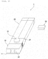
- FIG. 1 is a first perspective view schematically showing an overall configuration of a side protection device for a vehicle according to a first embodiment of the present invention
- FIG. 2 is a second perspective view showing a state in which the side protection device for a vehicle according to the first embodiment shown in FIG. 1 is ready to be mounted on the vehicle
- FIG. 3 is a perspective view showing a deployed state of a guard unit according to the first embodiment shown in FIG. 1 .
- a side protection device 1 for a vehicle which may be easily and simply detachably attached, be held firmly in a fixed state, and minimize damage caused by foreign material on a surface of the vehicle thereto when detached, includes a main body housing 10, a guard unit 20 and a fixing unit 30.
- a side of a vehicle may refer to a side portion of the vehicle in which a door of the vehicle is disposed
- a pillar may refer to a pillar frame supporting a roof of the vehicle, as is well known.
- an A-pillar may refer to a frame disposed on a left/right side of a windshield glass on a front end of the vehicle
- a B-pillar may refer to a frame disposed between front and rear seat doors of the vehicle
- a C-pillar may refer to a frame disposed on a left/right side of a glass on a rear end of the vehicle.
- the main body housing 10 is configured to be detachably attached to the side of the vehicle.
- the main body housing 10 may include a magnetic pad 11 and thus be primarily detachably attached to the side of the vehicle by a magnetic force of the magnet pad 11.
- the main body housing 10 may further include an adhesive means enabling adhesion of the main body housing 10 to at least one side of the vehicle.
- main body housing 10 may further include a separation means 16 installed on the main body housing to allow the guard unit 20 to be spaced apart from the side of the vehicle by a predetermined distance.
- the separation means 16 is configured to be able to adjust a position of the guard unit 20 to allow the guard unit 20 to be spaced apart from the side of the vehicle by the predetermined distance (i.e. to have an adjusted distance from a door portion).
- the separation means 16 may be installed on the main body housing 10 to be connected to the guard unit 20 in a form of a shaft, and be implemented with a known drive means moving the guard unit 20 by the predetermined distance along an axial direction of the shaft.
- the separation means 16 may be provided to be remotely controlled by a user's manual operation or a separate operation means.
- the separation means 16 may be implemented using a spring structure or a lever structure.
- the separation means may be operated by a pedestrian detection sensor installed in the main body housing 10 or the guard unit 20. That is, based on a detection signal from the pedestrian detection sensor including a proximity sensor or an impact detection sensor, the separation means 16 may be configured to be driven by a control unit to axially move toward the door and thus not to obstruct movement of a pedestrian.
- the magnetic pad 11 may be coupled to one surface of the main body housing 10, and may include, for example, a rubber magnet or a known magnet. It is preferable that the magnetic pad 11 includes a permanent magnet having a certain level or more of magnetism to allow the magnetic pad to be held firmly in a fixed state to the side of the vehicle.
- one surface of the magnet pad 11, which is in contact with the surface of the vehicle may be sealed with a soft material such as silicon to minimize damage caused by detachment of the side protection device for a vehicle from the side of the vehicle, i.e. the surface of the vehicle.
- the guard unit 20 is configured to be installed to fit side curvatures of various vehicles and models, and serve to efficiently protect a large area of the vehicle from an external physical impact.
- the guard unit 20 is configured to be installed rotatably by an axis of the main body housing 10.
- the guard unit 20 may be deployed to extend/expand along a full-length direction of the vehicle for protecting the side of the vehicle from the external physical impact.
- the guard unit 20 may have a telescopic form (i.e. a form in which the guard unit 20 connected to a plurality of continuous frames 201 as shown in the drawings) so that a length of the guard unit 20 is adjusted in one direction.
- the guard unit 20 may have not only a style in which the guard unit 20 is deployed in both directions, but also a style in which the guard unit 20 is deployed in an inclined direction.
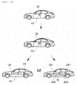
- the guard unit 20 may also be configured to have a style in which the guard unit 20 is deployed simultaneously in both the directions and the inclined direction. This configuration is described below with reference to FIG. 4 .
- the guard unit 20 is configured to be connected to the plurality of frames 201 in multiple stages so that one end of the guard unit 20 is folded, and the plurality of frames 201 are connected to each other by hinges 202, respectively.
- the side protection device for a vehicle may systematically fold the guard unit 20 to fit the side curvatures of various vehicles, and as a result, may be easily installed to fit the curvatures of the various vehicles.
- the hinges may be configured to be perpendicularly connected to each other in the axial direction and thus be rotated in X, Y or Z axis direction. This configuration is described in more detail with reference to FIG. 13.
- the guard unit 20 may further include a support member 22 coupled to one surface of the guard unit 20, detachably attached to the surface of the vehicle by the magnetic force, and supporting the guard unit to be fixed to the surface of the vehicle. Accordingly, an overall weight of a guard member protecting the side of the vehicle may be distributed by the support member 22, thereby improving durability and enabling efficient impact dispersion even against external impact.
- the fixing unit 30 is configured to serve to allow the main body housing 10 to be easily and simply detachably attached to the side of the vehicle while allowing the main body housing 10 to be held firmly in a fixed state to the side of the vehicle.
- the fixing unit 30 is configured to be installed in the main body housing 10 for locking and fixing the main body housing 10 to the side of the vehicle by a manual operation.
- the fixing unit 30 may include a clamp 31 and a fastening switch 32.
- the clamp 31 may be built in the main body housing 10 and locked and fixed to the side of the vehicle. That is, the clamp 31 is configured to be locked and fixed to the side of the vehicle, i.e. an edge of a vehicle door.
- the clamp 31 may have a clip form. That is, the clamp 31 is configured to be built in or protrude from the main body housing 10 based on an operation of the fastening switch 32 to be described below.
- the clamp 31 may be pulled out of/built in the main body housing 10. That is, when the fastening switch 32 is rotated from the main body housing 10, the clamp 31 may be configured to be interlocked with the fastening switch 32 and protrude outward from the main body housing 10. Therefore, the clamp 31 may press the edge of the vehicle door by such a systematic drive between the fastening switch 32 and the clamp 31. As a result, the main body housing 10 may be held more tightly in a locked and fixed state to the side of the vehicle.
- the side protection device 1 for a vehicle of the present invention may attach the main body housing 10 to the side of the vehicle, i.e. a vehicle door adjacent to a vehicle pillar. Then, the guard unit 20 attached to the main body housing 10 may be deployed in both directions, and then deployed in a telescoping manner to be completely mounted on the side of the vehicle.
- the guard unit 20 may include a horizontal guard unit 201 and an inclined guard unit 202.
- the guard unit 20 may include only either the horizontal guard unit 201 or the inclined guard unit 202. In case that the guard unit 20 includes both the horizontal guard unit 201 and the inclined guard unit 202, the side of the vehicle may be protected even when the vehicle has an unusual shape (for example, a protruding fender portion).
- the description describes that the side protection device 1 is coupled to a side of the door with reference to FIG. 5 .
- the main body housing 10 may include the magnetic pad 11, and be attached to and thus primarily fixed to the side of the vehicle by the magnetic force of the magnetic pad 11.
- the clamp 31 built in the main body housing 10 may be interlocked with the fastening switch 32 and pulled out of the main body housing 10, based on the operation of the fastening switch 32.
- the main body housing 10 may be secondly fixed to the side of the vehicle by clipping and fixing the pulled-out clamp 31 to the edge of the vehicle door D.
- the clamp 31 having the clip form may be clipped and fixed to the end of the vehicle door D.
- the fastening switch 32 is manually operated, as the clamp 31 is fixed while pressing the end of the vehicle door D by a pull-out/built-in operation of the clamp 31, the main body housing 10 may be held more tightly and firmly in a fixed state to a side panel P of the vehicle.
- the description focuses on a side protection device for a vehicle according to a second embodiment of the present invention.
- the side protection device for a vehicle in the second embodiment may be automatically attached to the vehicle using an adapter housing attached to the vehicle.
- FIG. 6 is a perspective view schematically showing an overall configuration of a side protection device for a vehicle according to a second embodiment of the present invention
- FIG. 7 is a perspective view showing a main body housing according to the second embodiment shown in FIG. 6
- FIG. 8 is a plan view showing an adapter housing according to the second embodiment shown in FIG. 6
- FIG. 9 is a side cross-sectional view showing a state in which the main body housing and the adapter housing, according to the second embodiment shown in FIG. 6 , are detachably attached to each other
- FIG. 10 is a view for explaining a state in which the side protection device for a vehicle according to the second embodiment shown in FIG. 6 is coupled to a side of the vehicle.
- the side protection device 10 for a vehicle may include an adapter housing 40, a main body housing 10, a guard unit 20 and a fixing unit 30.
- the adapter housing 40 may be detachably attached to a vehicle door.
- the adapter housing 40 may include a magnet pad 11 on one surface thereof, and thus be detachably attached to the vehicle door, i.e. the side of the vehicle by a first magnetic force generated from the magnet pad 11.
- the adapter housing 40 may include a coupling groove 41 and a column 43.
- the coupling groove 41 may be formed to be recessed in one end of the adapter housing 40 to guide the main body housing 10 to be detachably attached to the adapter housing 40.
- the column 43 may be formed to protrude from the coupling groove 41 in a column form, and extend from one surface of the coupling groove 41.
- the column 43 may include a locking jaw 42 and a bar magnet 44.
- the locking jaw 42 may be formed to extend radially at an end of the column 43.
- the bar magnet 44 may serve to provide a second magnetic force, and may preferably be a permanent magnet such as neodymium.
- the main body housing 10 is configured to be detachably attached to the adapter housing 40 by the second magnetic force.
- the main body housing 10 may include a docking switch 12 and a clamp groove 13.
- the docking switch 12 is configured to be installed to the main body housing 10 and driven by sensing the second magnetic force generated from the adapter housing 40.
- the clamp groove 13 may be installed to the main body housing 10 and physically driven depending on a drive of the docking switch 12 to be locked and fixed to/unlocked from the adapter housing 40.
- the clamp groove 13 is configured to be formed in a ring shape an end of which is locked to the locking jaw 42 of the column 43, locked and fixed to/unlocked from the locking jaw 42 by sensing the second magnetic force of the main body housing 10, and driven typically by an actuator providing a physical drive force.
- the main body housing 10 may include a battery 14 and a control unit 15.
- the battery 14 may supply the docking switch 12 with driving power, and may be formed of, for example, a rechargeable secondary battery.
- the control unit 15 may be configured to be installed in the main body housing 10 and remotely controlling the docking switch 12 in case that a user operates a user terminal such as a smart-phone or a smart key of the vehicle.
- the control unit 15 may be configured to include a communication module 151 receiving a control signal from the user terminal or the smart key of the vehicle and a control module 152 controlling a drive of the docking switch 12 based on the control signal received by the communication module 151.
- a signal for remotely controlling the docking switch 12 may be transmitted by a separate short-range communication module as well as the user terminal, or a fingerprint sensor formed in the main body housing.
- the main body housing 10 may further include a separation means 16.
- the separation means 16 is configured to be installed on the main body housing 10 for allowing the guard unit 20 to be separated from the side of the vehicle by a predetermined distance.
- the separation means 16 may be implemented by a known actuator connected to the guard unit 20 for physically moving the guard unit 20.
- main body housing 10 may further include a rubber packing 17.
- the rubber packing 17 may be coupled to one surface of the main body housing 10 facing the coupling groove 41 in case that the main body housing 10 and the adapter housing 40 are coupled to each other.
- the rubber packing 17 may preferably be made of an elastic material having elasticity such as rubber material or silicone.
- the rubber packing 17 may be formed to have an inclined surface 171.
- the inclined surface 171 among circumferential surfaces of the rubber packing 17 may correspond to an inclined surface among inner circumferential surfaces of the coupling groove 41.
- a plurality of guard units 20 are configured to be rotatably coupled to the main body housing 10, having a length varied in one direction about a rotation axis, and protecting a surface of the vehicle from a physical impact.
- the fixing unit 30 may be configured to be provided in the adapter housing 40 and serve to fix the adapter housing 40 to the side of the vehicle.
- the fixing unit 30 may be a clamp 31 locked and fixed to an edge of the vehicle door corresponding to the side of the vehicle in a clip form.
- the clamp 31 may include a detachment prevention pin 311 bent from an end of the clamp 31 and disposed between the edge of the vehicle door and an adjacent vehicle pillar when the vehicle door is closed for preventing the adapter housing 40 from being detached from the side of the vehicle.
- the side protection device 1 for a vehicle may detachably attach the adapter housing 40 to the side of the vehicle, i.e. the vehicle door by a first magnetic force generated from the magnetic pad 11. Therefore, the adapter housing 40 may be primarily fixed to the vehicle door by the first magnetic force.
- the clamp 31 of the fixing unit 30 may be fixed to the edge of the vehicle door, i.e. the end of the door in contact with the pillar of the vehicle, and thus the adapter housing 40 may be secondarily fixed to the vehicle door.
- the detachment prevention pin 311 may be disposed between the vehicle door and the vehicle pillar, and thus the adapter housing 40 may not be detached but be held firmly in a fixed state when the vehicle door is closed.
- the adapter housing 40 may be prevented not only from being forcibly detached by an external impact, but also from being stolen.
- the adapter housing 40 may be coupled to the main body housing 10 through the coupling groove 41 of the adapter housing 40.
- the clamp groove 13 of the main body housing 10 may be inserted into the coupling groove 41 of the adapter housing 40.
- the docking switch 12 of the adapter housing 40 may sense the second magnetic force generated from the bar magnet 44 built in the column 43.
- the docking switch 12 may drive the clamp groove 13 based on the sensed second magnetic force, and then the clamp groove 13 may be physically driven to be locked and fixed to the locking jaw 42 of the column 43.
- the main body housing 10 may be tightly coupled to the adapter housing 40 by the rubber packing 17, and simply and quickly coupled to the adapter housing 40 because the inclined surface 171 guides a coupling position of the main body housing 10 and the adapter housing 40.
- the drive of the docking switch 12 for the coupling of the main body housing 10 and the adapter housing 40 may be remotely controlled by the control unit 15.
- the above driving may be controlled based on a control of the control module 152 depending on a network communication between an application activated on the user's smart-phone and the communication module 151.
- the operation of the switch module 12 or the guard unit 20 may be controlled, being interlocked with various signals based on a driving of the vehicle (for example, vehicle start on/off).
- the guard unit 20 may be rotated about the main body housing 10 in a state where the main body housing 10 is coupled to the adapter housing 40.
- the guard unit 20 may be installed rotatably by a rotation axis with respect to the main body housing 10, and thus the guard unit 20 may be rotated along the axial direction of the rotation axis.
- guard unit 20 may be deployed to extend/be reduced along a full-length direction of the vehicle in a telescoping manner.
- the guard unit 20 may then protect the side of the vehicle from an external physical impact.
- the guard unit 20 may protect the sides of the various vehicles by being folded to fit a side curvature of the vehicle by hinges 21 connected to the guard unit 20.
- a support member 22 may be coupled between the guard unit 20 and the side of the vehicle to support the guard unit 20, thereby distributing a weight of the guard unit 20 and improving durability of the guard unit 20 against the external impact.
- a side protection device for a vehicle which may be more conveniently attached to a door surface of a vehicle, is described in more detail with reference to FIGS. 11 and 12 .
- FIG. 11 is a perspective view schematically showing an overall configuration of a side protection device for a vehicle according to a third embodiment of the present invention.
- the side protection device for a vehicle according to the third embodiment shown in FIG. 11 is different from those according to the first embodiment and the second embodiment in having components such as an attachment button 32' and a fixing clip 13-1.
- a clip guide portion 13-2 may be formed at a side of a main body housing 10 detachably attached to a side of a vehicle.
- the fixing clip 13-1 may be formed to protrude in an arc shape based on an input signal of the attachment button 32' and thus function to be locked and fixed to the door of the vehicle.
- the attachment button 32' may be formed on a bottom surface of the main body housing 10.
- the clip guide portion 13-2 may have a c shape having an opening for the fixing clip 13-1.
- the clip guide portion 13-2 is not limited to having this shape, and may be configured to have various shapes such as a shape in which the clip guide portions 13-2 protrude from both sides of the fixing clip 13-1.
- the attachment button 32' may be naturally pressed. Accordingly, the fixing clip 13-1 built in the main body housing 10 may be fixed to the edge of the vehicle door while being rotated in the arc shape in a state where the mounting of the fixing clip 13-1 is guided by the clip guide portion 13-2.
- a built-in metal detection sensor (not shown) may be used together. That is, the metal detection sensor may check whether the side protection device for a vehicle is tightly attached to the vehicle door which is made of metal.
- a built-in motor (not shown) may start its operation, and thus the fixing clip 13-1 may protrude.
- two or more attachment buttons 32' may be formed on the bottom surface of the main body housing 10, and the fixing clip 13-1 may be configured to protrude when pressing signals are generated from both of these buttons 32'.
- FIG. 12 is a view showing another example of the guard unit 20 which may be applied to the side protection device for a vehicle according to the first to third embodiments of the present invention.
- the guard unit 20 When rotated in the main body housing 10 and deployed horizontally, the guard unit 20 may need to be rotated in one of three axis directions due to a shape of the vehicle or various other reasons.
- hinge shafts 202 and 203 may be installed between frames 201.
- the hinge shafts 202 and 203 may be installed continuously, and may be perpendicular to each other, respectively.
- the hinge shafts 202 and 203 may be rotated in all three X, Y, and Z axis directions.
- the present invention may be easily and simply detachably attached, be held firmly in the fixed state, and minimize damage caused by foreign material on the surface of the vehicle thereto when detached.
- the present invention may be installed to fit the side curvatures of various vehicles and models, and may effectively protect a large area of the vehicle from the external physical impact.
Landscapes
- Engineering & Computer Science (AREA)
- Mechanical Engineering (AREA)
- Fittings On The Vehicle Exterior For Carrying Loads, And Devices For Holding Or Mounting Articles (AREA)
Abstract
Description
- The present invention relates to a side protection device for a vehicle.
- In general, a large building (apartment, mall, office building or the like) has a secured parking space by dividing a parking row so that multiple vehicles can be parked in a row. In the secured parking space, the vehicles may be parked to have a certain separation distance from each other to the left and right, respectively.
- Here, after the vehicle is parked in the divided parking row, in case that a vehicle door is opened for a passenger to get out of the vehicle, the separation distance between parked vehicles is generally smaller than a swing radius of the vehicle door which is opened.
- Therefore, there may frequently occur the following situations: where edges of left and right vehicle doors which are opened cause damage such as scratching or packing to sides of neighboring vehicles parked; on the contrary, where sides of the vehicle are damaged by the neighboring vehicles.
- The prior art thus discloses a sponge-type impact absorbing pad having a predetermined size and attached to one end of the vehicle door to absorb an external impact.
- However, the prior impact absorbing pad is to be attached to a surface of the vehicle, and thus has the following problems: it is troublesome to replace the pad; there is a risk of damage caused by dust or foreign material which is attached on the surface of the vehicle thereto when the pad is detached; and the pad is easily stolen.
- An object of the present invention is to provide a side protection device for a vehicle which is easily and simply detachably attached, is held firmly in a fixed state, and minimizes damage caused by foreign material on a surface of the vehicle thereto when detached.
- Another object of the present invention is to provide a side protection device for a vehicle, capable of being installed to fit side curvatures of various vehicles and models, and effectively protecting a large area of the vehicle from an external physical impact.
- The objects of the present invention are not limited to those mentioned above, and other effects that are not mentioned are clearly understood by those skilled in the art from the following description.
- According to an embodiment of the present invention, there is provided side protection device for a vehicle including: a main body housing detachably attached to a side of the vehicle; a guard unit rotatably installed to the main body housing and deployed along a full-length direction of the vehicle for protecting the side of the vehicle from an external physical impact; and a fixing unit installed in the main body housing for locking and fixing the main body housing to the side of the vehicle by a manual operation.
- In addition, the main body housing may include a magnetic pad allowing the main body housing to be detachably attached to the side of the vehicle by a magnetic force.
- In addition, the guard unit may have a telescopic form so that a length of the guard unit is adjusted in one direction, and connected to hinges in multiple stages so that one end of the guard unit is folded.
- In addition, the guard unit may further include a support member coupled to the guard unit, detachably attached to a surface of the vehicle by the magnetic force, and supporting the guard unit to be fixed to the surface of the vehicle.
- In addition, the fixing unit may include a clamp and a fastening switch, the clamp being built in the main body housing and locked and fixed to the side of the vehicle, and the fastening switch allowing the clamp to be pulled out of/built in the main body housing by the manual operation.
- In addition, the clamp may have a clip form.
- Meanwhile, according to another embodiment of the present invention, there is provided a side protection device for a vehicle including: an adapter housing detachably attached to a vehicle door by a first magnetic force; a main body housing detachably attached to the adapter housing by a second magnetic force; a plurality of guard units rotatably coupled to the main body housing, having a length varied in one direction about a rotation axis, and protecting a surface of the vehicle from a physical impact; and a fixing unit provided in the adapter housing and fixing the adapter housing to the side of the vehicle.
- In addition, the adapter housing may include a coupling groove and a column, the coupling groove being formed to be recessed in one surface of the adapter housing to guide the main body housing to be coupled to the adapter housing, and the column being formed to extend from one surface of the coupling groove and having a locking jaw extending radially at an end of the column and a bar magnet built in the column and providing the second magnetic force.
- In addition, the main body housing may include a docking switch and a docking clamp , the docking switch being installed on the main body housing and driven by sensing the second magnetic force generated from the adapter housing, and the docking clamp being installed in the main body housing and driven depending on a drive of the docking switch to be locked and fixed to/unlocked from the adapter housing.
- In addition, the main body housing may include a battery and a control unit, the battery being installed in the main body housing for supplying the docking switch with driving power, and the control unit being installed in the main body housing and remotely controlling the docking switch in case that a user operates a user terminal or a smart key of the vehicle.
- In addition, the main body housing may further include a separation means installed on the main body housing for allowing the guard unit to be separated from the side of the vehicle by a predetermined distance.
- In addition, the side protection device for a vehicle may further include a pedestrian detection sensor and a control unit, the pedestrian detection sensor being installed in the main body housing or the guard unit, and the control unit driving the separation means based on a detection signal from the pedestrian detection sensor.
- In addition, the pedestrian detection sensor may include a proximity sensor or an impact detection sensor.
- In addition, the main body housing may further include a rubber packing coupled to one surface of the main body housing facing the coupling groove in case that the main body housing and the adapter housing are coupled to each other.
- In addition, the rubber packing may have an inclined surface among its circumferential surfaces, the inclined surface corresponding to an inclined surface among inner circumferential surfaces of the coupling groove.
- In addition, the control unit may include a communication module and a control module, the communication module receiving a control signal from the user terminal or the smart key of the vehicle, and the control module controlling a drive of the docking switch based on the control signal received by the communication module.
- In addition, the fixing unit may be a clamp locked and fixed to an edge of the vehicle door corresponding to the side of the vehicle in a clip form.
- In addition, the clamp may include a detachment prevention pin bent from an end of the clamp and disposed between the edge of the vehicle door and an adjacent vehicle pillar when the vehicle door is closed for preventing the adapter housing from being detached from the side of the vehicle.
- According to still another embodiment of the present invention, there is provided a side protection device for a vehicle including: a main body housing detachably attached to a side of the vehicle; a guard unit rotatably installed to the main body housing and deployed along a full-length direction of the vehicle for protecting the side of the vehicle from an external physical impact; a fixing clip built in a side of the main body housing and protruding from the main body housing to lock and fix the main body housing to the side of the vehicle; and an attachment button allowing the fixing clip to protrude and installed in the main body housing.
- Here, at least two attachment buttons are formed on one surface of the main body housing.
- Here, the fixing clip built in the main body housing may protrude in an arc shape by a button operation of the attachment button to be fixed to a frame edge of the vehicle.
- Here, the side protection device for a vehicle may further include a clip guide portion formed on the main body housing.
- According to the present invention, by the magnetic pad and the fixing unit, the side protection device for a vehicle may be easily and simply detachably attached, be held firmly in a fixed state, and minimize damage caused by foreign material on a surface of the vehicle thereto when detached.
- In addition, by the guard unit, the side protection device for a vehicle according to the present invention may be installed to fit side curvatures of various vehicles and models, and may effectively protect a large area of the vehicle from an external physical impact.
- The effects of the present invention are not limited to those mentioned above, and other effects that are not mentioned are clearly understood by those skilled in the art from the following description.
-
-
FIG. 1 is a first perspective view schematically showing an overall configuration of a side protection device for a vehicle according to a first embodiment of the present invention. -
FIG. 2 is a second perspective view showing a state in which the side protection device for a vehicle according to the first embodiment shown inFIG. 1 is ready to be mounted on the vehicle. -
FIG. 3 is a perspective view showing a deployed state of a guard unit according to the first embodiment shown inFIG. 1 . -
FIG. 4 is an exemplary view showing usages of the side protection device for a vehicle according to the first embodiment shown inFIG. 1 . -
FIG. 5 is a view for explaining a state in which the side protection device for a vehicle according to the first embodiment shown inFIG. 1 is coupled to a side of the vehicle. -
FIG. 6 is a perspective view schematically showing an overall configuration of a side protection device for a vehicle according to a second embodiment of the present invention. -
FIG. 7 is a perspective view showing a main body housing according to the second embodiment shown inFIG. 6 . -
FIG. 8 is a plan view showing an adapter housing according to the second embodiment shown inFIG. 6 . -
FIG. 9 is a side cross-sectional view showing a state in which the main body housing and the adapter housing, according to the second embodiment shown inFIG. 6 , are detachably attached to each other. -
FIG. 10 is a view for explaining a state in which the side protection device for a vehicle according to the second embodiment shown inFIG. 6 is coupled to a side of the vehicle. -
FIG. 11 is a perspective view schematically showing an overall configuration of a side protection device for a vehicle according to a third embodiment of the present invention. -
FIG. 12 is a view showing another example of the guard unit which may be applied to the side protection device for a vehicle according to the first to third embodiments of the present invention. - Hereinafter, embodiments of the present invention are described in detail with reference to the accompanying drawings. Various advantages and features of the present invention and methods accomplishing them become apparent from the following description of exemplary embodiments with reference to the accompanying drawings. However, the present invention is not limited to exemplary embodiments to be described below, but may be implemented in various different forms. These exemplary embodiments are provided only in order to make the present invention complete and allow those skilled in the art to completely recognize the scope of the present invention, and the present invention is defined by the scope of the claims. Throughout the specification, like reference numerals denote like elements.
- Unless defined otherwise, all terms (including technical and scientific terms) used in the present specification have the same meaning as meanings commonly understood by those skilled in the art to which the present invention pertains. In addition, terms generally used and defined in a dictionary are not to be interpreted as having ideal or excessive meanings unless clearly indicated.
- Hereinafter, a side protection device 1 for a vehicle according to embodiments of the present invention is described with reference to the drawings.
-
FIG. 1 is a first perspective view schematically showing an overall configuration of a side protection device for a vehicle according to a first embodiment of the present invention;FIG. 2 is a second perspective view showing a state in which the side protection device for a vehicle according to the first embodiment shown inFIG. 1 is ready to be mounted on the vehicle; andFIG. 3 is a perspective view showing a deployed state of a guard unit according to the first embodiment shown inFIG. 1 . - Referring to
FIGS. 1 to 3 , a side protection device 1 for a vehicle according to an embodiment of the present invention, which may be easily and simply detachably attached, be held firmly in a fixed state, and minimize damage caused by foreign material on a surface of the vehicle thereto when detached, includes amain body housing 10, aguard unit 20 and afixing unit 30. - Here, a side of a vehicle may refer to a side portion of the vehicle in which a door of the vehicle is disposed, and a pillar may refer to a pillar frame supporting a roof of the vehicle, as is well known. (For example, an A-pillar may refer to a frame disposed on a left/right side of a windshield glass on a front end of the vehicle, a B-pillar may refer to a frame disposed between front and rear seat doors of the vehicle, and a C-pillar may refer to a frame disposed on a left/right side of a glass on a rear end of the vehicle.
- The
main body housing 10 is configured to be detachably attached to the side of the vehicle. Themain body housing 10 may include amagnetic pad 11 and thus be primarily detachably attached to the side of the vehicle by a magnetic force of themagnet pad 11. In addition, themain body housing 10 may further include an adhesive means enabling adhesion of themain body housing 10 to at least one side of the vehicle. - In addition, the
main body housing 10 may further include a separation means 16 installed on the main body housing to allow theguard unit 20 to be spaced apart from the side of the vehicle by a predetermined distance. - The separation means 16 is configured to be able to adjust a position of the
guard unit 20 to allow theguard unit 20 to be spaced apart from the side of the vehicle by the predetermined distance (i.e. to have an adjusted distance from a door portion). For example, the separation means 16 may be installed on themain body housing 10 to be connected to theguard unit 20 in a form of a shaft, and be implemented with a known drive means moving theguard unit 20 by the predetermined distance along an axial direction of the shaft. Here, the separation means 16 may be provided to be remotely controlled by a user's manual operation or a separate operation means. - The separation means 16 may be implemented using a spring structure or a lever structure. In addition, the separation means may be operated by a pedestrian detection sensor installed in the
main body housing 10 or theguard unit 20. That is, based on a detection signal from the pedestrian detection sensor including a proximity sensor or an impact detection sensor, the separation means 16 may be configured to be driven by a control unit to axially move toward the door and thus not to obstruct movement of a pedestrian. - The
magnetic pad 11 may be coupled to one surface of themain body housing 10, and may include, for example, a rubber magnet or a known magnet. It is preferable that themagnetic pad 11 includes a permanent magnet having a certain level or more of magnetism to allow the magnetic pad to be held firmly in a fixed state to the side of the vehicle. - In addition, one surface of the
magnet pad 11, which is in contact with the surface of the vehicle, may be sealed with a soft material such as silicon to minimize damage caused by detachment of the side protection device for a vehicle from the side of the vehicle, i.e. the surface of the vehicle. - The
guard unit 20 is configured to be installed to fit side curvatures of various vehicles and models, and serve to efficiently protect a large area of the vehicle from an external physical impact. - The
guard unit 20 is configured to be installed rotatably by an axis of themain body housing 10. Theguard unit 20 may be deployed to extend/expand along a full-length direction of the vehicle for protecting the side of the vehicle from the external physical impact. - The
guard unit 20 may have a telescopic form (i.e. a form in which theguard unit 20 connected to a plurality ofcontinuous frames 201 as shown in the drawings) so that a length of theguard unit 20 is adjusted in one direction. In addition, theguard unit 20 may have not only a style in which theguard unit 20 is deployed in both directions, but also a style in which theguard unit 20 is deployed in an inclined direction. Theguard unit 20 may also be configured to have a style in which theguard unit 20 is deployed simultaneously in both the directions and the inclined direction. This configuration is described below with reference toFIG. 4 . - Here, the
guard unit 20 is configured to be connected to the plurality offrames 201 in multiple stages so that one end of theguard unit 20 is folded, and the plurality offrames 201 are connected to each other byhinges 202, respectively. Accordingly, the side protection device for a vehicle may systematically fold theguard unit 20 to fit the side curvatures of various vehicles, and as a result, may be easily installed to fit the curvatures of the various vehicles. That is, the hinges may be configured to be perpendicularly connected to each other in the axial direction and thus be rotated in X, Y or Z axis direction. This configuration is described in more detail with reference to FIG. 13. - In addition, the
guard unit 20 may further include asupport member 22 coupled to one surface of theguard unit 20, detachably attached to the surface of the vehicle by the magnetic force, and supporting the guard unit to be fixed to the surface of the vehicle. Accordingly, an overall weight of a guard member protecting the side of the vehicle may be distributed by thesupport member 22, thereby improving durability and enabling efficient impact dispersion even against external impact. - The fixing
unit 30 is configured to serve to allow themain body housing 10 to be easily and simply detachably attached to the side of the vehicle while allowing themain body housing 10 to be held firmly in a fixed state to the side of the vehicle. - The fixing
unit 30 is configured to be installed in themain body housing 10 for locking and fixing themain body housing 10 to the side of the vehicle by a manual operation. To this end, the fixingunit 30 may include aclamp 31 and afastening switch 32. - The
clamp 31 may be built in themain body housing 10 and locked and fixed to the side of the vehicle. That is, theclamp 31 is configured to be locked and fixed to the side of the vehicle, i.e. an edge of a vehicle door. Theclamp 31 may have a clip form. That is, theclamp 31 is configured to be built in or protrude from themain body housing 10 based on an operation of thefastening switch 32 to be described below. - Based on the opening and closing operation of the
fastening switch 32, theclamp 31 may be pulled out of/built in themain body housing 10. That is, when thefastening switch 32 is rotated from themain body housing 10, theclamp 31 may be configured to be interlocked with thefastening switch 32 and protrude outward from themain body housing 10. Therefore, theclamp 31 may press the edge of the vehicle door by such a systematic drive between thefastening switch 32 and theclamp 31. As a result, themain body housing 10 may be held more tightly in a locked and fixed state to the side of the vehicle. - Hereinafter, the description focuses on usages of the side protection device for a vehicle according to the embodiment of the present invention, which is configured as described above.
-
FIG. 4 is an exemplary view showing usages of the side protection device for a vehicle according to the first embodiment shown inFIG. 1 ; andFIG. 5 is a view for explaining a state in which the side protection device for a vehicle according to the first embodiment shown inFIG. 1 is coupled to a side of the vehicle. - Referring to
FIGS. 4 and5 , when the vehicle is parked, the side protection device 1 for a vehicle of the present invention may attach themain body housing 10 to the side of the vehicle, i.e. a vehicle door adjacent to a vehicle pillar. Then, theguard unit 20 attached to themain body housing 10 may be deployed in both directions, and then deployed in a telescoping manner to be completely mounted on the side of the vehicle. Here, theguard unit 20 may include ahorizontal guard unit 201 and aninclined guard unit 202. Alternatively, theguard unit 20 may include only either thehorizontal guard unit 201 or theinclined guard unit 202. In case that theguard unit 20 includes both thehorizontal guard unit 201 and theinclined guard unit 202, the side of the vehicle may be protected even when the vehicle has an unusual shape (for example, a protruding fender portion). - Meanwhile, the description describes that the side protection device 1 is coupled to a side of the door with reference to
FIG. 5 . As shown inFIG. 5 , themain body housing 10 may include themagnetic pad 11, and be attached to and thus primarily fixed to the side of the vehicle by the magnetic force of themagnetic pad 11. - Next, when a user manually operates the
fastening switch 32 of the fixingunit 30, theclamp 31 built in themain body housing 10 may be interlocked with thefastening switch 32 and pulled out of themain body housing 10, based on the operation of thefastening switch 32. - In addition, while the vehicle door is opened, the
main body housing 10 may be secondly fixed to the side of the vehicle by clipping and fixing the pulled-out clamp 31 to the edge of the vehicle door D. - That is, the
clamp 31 having the clip form may be clipped and fixed to the end of the vehicle door D. - Here, in case that the
fastening switch 32 is manually operated, as theclamp 31 is fixed while pressing the end of the vehicle door D by a pull-out/built-in operation of theclamp 31, themain body housing 10 may be held more tightly and firmly in a fixed state to a side panel P of the vehicle. - Hereinafter, the description focuses on a side protection device for a vehicle according to a second embodiment of the present invention. Unlike in the first embodiment, the side protection device for a vehicle in the second embodiment may be automatically attached to the vehicle using an adapter housing attached to the vehicle.
-
FIG. 6 is a perspective view schematically showing an overall configuration of a side protection device for a vehicle according to a second embodiment of the present invention;FIG. 7 is a perspective view showing a main body housing according to the second embodiment shown inFIG. 6 ;FIG. 8 is a plan view showing an adapter housing according to the second embodiment shown inFIG. 6 ;FIG. 9 is a side cross-sectional view showing a state in which the main body housing and the adapter housing, according to the second embodiment shown inFIG. 6 , are detachably attached to each other; andFIG. 10 is a view for explaining a state in which the side protection device for a vehicle according to the second embodiment shown inFIG. 6 is coupled to a side of the vehicle. - Hereinafter, the second embodiment is described in detail, and the same components as those of the first embodiment are omitted for simple description of the invention.
- Referring to
FIGS. 6 to 10 , theside protection device 10 for a vehicle according to another embodiment of the present invention may include anadapter housing 40, amain body housing 10, aguard unit 20 and a fixingunit 30. - The
adapter housing 40 may be detachably attached to a vehicle door. Theadapter housing 40 may include amagnet pad 11 on one surface thereof, and thus be detachably attached to the vehicle door, i.e. the side of the vehicle by a first magnetic force generated from themagnet pad 11. Theadapter housing 40 may include acoupling groove 41 and acolumn 43. - The
coupling groove 41 may be formed to be recessed in one end of theadapter housing 40 to guide themain body housing 10 to be detachably attached to theadapter housing 40. - The
column 43 may be formed to protrude from thecoupling groove 41 in a column form, and extend from one surface of thecoupling groove 41. Thecolumn 43 may include a lockingjaw 42 and abar magnet 44. - The locking
jaw 42 may be formed to extend radially at an end of thecolumn 43. - The
bar magnet 44 may serve to provide a second magnetic force, and may preferably be a permanent magnet such as neodymium. - The
main body housing 10 is configured to be detachably attached to theadapter housing 40 by the second magnetic force. Themain body housing 10 may include a docking switch 12 and aclamp groove 13. - The docking switch 12 is configured to be installed to the
main body housing 10 and driven by sensing the second magnetic force generated from theadapter housing 40. - The
clamp groove 13 may be installed to themain body housing 10 and physically driven depending on a drive of the docking switch 12 to be locked and fixed to/unlocked from theadapter housing 40. For example, theclamp groove 13 is configured to be formed in a ring shape an end of which is locked to the lockingjaw 42 of thecolumn 43, locked and fixed to/unlocked from the lockingjaw 42 by sensing the second magnetic force of themain body housing 10, and driven typically by an actuator providing a physical drive force. - In addition, the
main body housing 10 may include abattery 14 and acontrol unit 15. - The
battery 14 may supply the docking switch 12 with driving power, and may be formed of, for example, a rechargeable secondary battery. - The
control unit 15 may be configured to be installed in themain body housing 10 and remotely controlling the docking switch 12 in case that a user operates a user terminal such as a smart-phone or a smart key of the vehicle. Thecontrol unit 15 may be configured to include acommunication module 151 receiving a control signal from the user terminal or the smart key of the vehicle and acontrol module 152 controlling a drive of the docking switch 12 based on the control signal received by thecommunication module 151. Here, a signal for remotely controlling the docking switch 12 may be transmitted by a separate short-range communication module as well as the user terminal, or a fingerprint sensor formed in the main body housing. - In addition, the
main body housing 10 may further include a separation means 16. The separation means 16 is configured to be installed on themain body housing 10 for allowing theguard unit 20 to be separated from the side of the vehicle by a predetermined distance. The separation means 16 may be implemented by a known actuator connected to theguard unit 20 for physically moving theguard unit 20. - In addition, the
main body housing 10 may further include arubber packing 17. - The rubber packing 17 may be coupled to one surface of the
main body housing 10 facing thecoupling groove 41 in case that themain body housing 10 and theadapter housing 40 are coupled to each other. The rubber packing 17 may preferably be made of an elastic material having elasticity such as rubber material or silicone. The rubber packing 17 may be formed to have aninclined surface 171. Theinclined surface 171 among circumferential surfaces of the rubber packing 17 may correspond to an inclined surface among inner circumferential surfaces of thecoupling groove 41. - A plurality of
guard units 20 are configured to be rotatably coupled to themain body housing 10, having a length varied in one direction about a rotation axis, and protecting a surface of the vehicle from a physical impact. - The fixing
unit 30 may be configured to be provided in theadapter housing 40 and serve to fix theadapter housing 40 to the side of the vehicle. - The fixing
unit 30 may be aclamp 31 locked and fixed to an edge of the vehicle door corresponding to the side of the vehicle in a clip form. - In addition, the
clamp 31 may include adetachment prevention pin 311 bent from an end of theclamp 31 and disposed between the edge of the vehicle door and an adjacent vehicle pillar when the vehicle door is closed for preventing theadapter housing 40 from being detached from the side of the vehicle. - The description specifically describes a usage example of the side protection device 1 for a vehicle according to another embodiment of the present invention, which is configured as described above.
- After parking the vehicle, the side protection device 1 for a vehicle according to another embodiment of the present invention may detachably attach the
adapter housing 40 to the side of the vehicle, i.e. the vehicle door by a first magnetic force generated from themagnetic pad 11. Therefore, theadapter housing 40 may be primarily fixed to the vehicle door by the first magnetic force. - Then, the
clamp 31 of the fixingunit 30 may be fixed to the edge of the vehicle door, i.e. the end of the door in contact with the pillar of the vehicle, and thus theadapter housing 40 may be secondarily fixed to the vehicle door. - Here, when the vehicle door is closed, the
detachment prevention pin 311 may be disposed between the vehicle door and the vehicle pillar, and thus theadapter housing 40 may not be detached but be held firmly in a fixed state when the vehicle door is closed. - Therefore, the
adapter housing 40 may be prevented not only from being forcibly detached by an external impact, but also from being stolen. - Next, the
adapter housing 40 may be coupled to themain body housing 10 through thecoupling groove 41 of theadapter housing 40. - In detail, the
clamp groove 13 of themain body housing 10 may be inserted into thecoupling groove 41 of theadapter housing 40. In this process, when themain body housing 10 and theadapter housing 40 come close to each other by a predetermined distance, the docking switch 12 of theadapter housing 40 may sense the second magnetic force generated from thebar magnet 44 built in thecolumn 43. - Then, the docking switch 12 may drive the
clamp groove 13 based on the sensed second magnetic force, and then theclamp groove 13 may be physically driven to be locked and fixed to the lockingjaw 42 of thecolumn 43. - Here, the
main body housing 10 may be tightly coupled to theadapter housing 40 by the rubber packing 17, and simply and quickly coupled to theadapter housing 40 because theinclined surface 171 guides a coupling position of themain body housing 10 and theadapter housing 40. - In addition, the drive of the docking switch 12 for the coupling of the
main body housing 10 and theadapter housing 40 may be remotely controlled by thecontrol unit 15. For example, the above driving may be controlled based on a control of thecontrol module 152 depending on a network communication between an application activated on the user's smart-phone and thecommunication module 151. The operation of the switch module 12 or theguard unit 20 may be controlled, being interlocked with various signals based on a driving of the vehicle (for example, vehicle start on/off). - Therefore, it is not only possible to easily and automatically couple and fasten the
main body housing 10 and theadapter housing 40 to each other, but also possible to simply and quickly control this coupling and fastening. - Next, the
guard unit 20 may be rotated about themain body housing 10 in a state where themain body housing 10 is coupled to theadapter housing 40. - For example, the
guard unit 20 may be installed rotatably by a rotation axis with respect to themain body housing 10, and thus theguard unit 20 may be rotated along the axial direction of the rotation axis. - In addition, the
guard unit 20 may be deployed to extend/be reduced along a full-length direction of the vehicle in a telescoping manner. - The
guard unit 20 may then protect the side of the vehicle from an external physical impact. - Here, the
guard unit 20 may protect the sides of the various vehicles by being folded to fit a side curvature of the vehicle byhinges 21 connected to theguard unit 20. - In addition, a
support member 22 may be coupled between theguard unit 20 and the side of the vehicle to support theguard unit 20, thereby distributing a weight of theguard unit 20 and improving durability of theguard unit 20 against the external impact. - Hereinafter, a side protection device for a vehicle according to a third embodiment of the present invention, which may be more conveniently attached to a door surface of a vehicle, is described in more detail with reference to
FIGS. 11 and 12 . -
FIG. 11 is a perspective view schematically showing an overall configuration of a side protection device for a vehicle according to a third embodiment of the present invention. The side protection device for a vehicle according to the third embodiment shown inFIG. 11 is different from those according to the first embodiment and the second embodiment in having components such as an attachment button 32' and a fixing clip 13-1. As shown in the drawing, a clip guide portion 13-2 may be formed at a side of amain body housing 10 detachably attached to a side of a vehicle. In a state where mounting of the fixing clip 13-1 is guided by the clip guide portion 13-2, the fixing clip 13-1 may be formed to protrude in an arc shape based on an input signal of the attachment button 32' and thus function to be locked and fixed to the door of the vehicle. Here, the attachment button 32' may be formed on a bottom surface of themain body housing 10. - As shown in the drawing, the clip guide portion 13-2 may have a c shape having an opening for the fixing clip 13-1. The clip guide portion 13-2 is not limited to having this shape, and may be configured to have various shapes such as a shape in which the clip guide portions 13-2 protrude from both sides of the fixing clip 13-1.
- As the side protection device for a vehicle according to the third embodiment is attached to an edge of a vehicle door, the attachment button 32' may be naturally pressed. Accordingly, the fixing clip 13-1 built in the
main body housing 10 may be fixed to the edge of the vehicle door while being rotated in the arc shape in a state where the mounting of the fixing clip 13-1 is guided by the clip guide portion 13-2. Here, a built-in metal detection sensor (not shown) may be used together. That is, the metal detection sensor may check whether the side protection device for a vehicle is tightly attached to the vehicle door which is made of metal. In addition to this metal detection signal, when a pressing signal of the attachment button 32' is generated together, a built-in motor (not shown) may start its operation, and thus the fixing clip 13-1 may protrude. Here, two or more attachment buttons 32' may be formed on the bottom surface of themain body housing 10, and the fixing clip 13-1 may be configured to protrude when pressing signals are generated from both of these buttons 32'. - Hereinafter, a rotational operation of the
guard unit 20 is described with reference toFIG. 12 . -
FIG. 12 is a view showing another example of theguard unit 20 which may be applied to the side protection device for a vehicle according to the first to third embodiments of the present invention. When rotated in themain body housing 10 and deployed horizontally, theguard unit 20 may need to be rotated in one of three axis directions due to a shape of the vehicle or various other reasons. In this case, as illustrated inFIG. 12 ,hinge shafts frames 201. Thehinge shafts hinge shafts - As set forth above, the present invention may be easily and simply detachably attached, be held firmly in the fixed state, and minimize damage caused by foreign material on the surface of the vehicle thereto when detached. In addition, the present invention may be installed to fit the side curvatures of various vehicles and models, and may effectively protect a large area of the vehicle from the external physical impact.
- Although exemplary embodiments of the present invention are described with reference to the accompanying drawings, those skilled in the art are expected to appreciate that various modifications and alterations may be made without departing from the spirit or essential feature of the present invention. Therefore, it is to be understood that exemplary embodiments described hereinabove are illustrative rather than being restrictive in all aspects.
Claims (22)
- A side protection device for a vehicle, comprising:a main body housing detachably attached to a side of the vehicle;a guard unit rotatably installed to the main body housing and deployed along a full-length direction of the vehicle for protecting the side of the vehicle from an external physical impact; anda fixing unit installed in the main body housing for locking and fixing the main body housing to the side of the vehicle by a manual operation.
- The side protection device for a vehicle of claim 1, wherein the main body housing includes a magnetic pad allowing the main body housing to be detachably attached to the side of the vehicle by a magnetic force.
- The side protection device for a vehicle of claim 1, wherein the guard unit has a telescopic form so that a length of the guard unit is adjusted in one direction, and extends by at least two hinges continuously connected to each other so that one end of the guard unit is folded.
- The side protection device for a vehicle of claim 1, wherein the guard unit further includes a support member coupled to the guard unit, detachably attached to a surface of the vehicle by the magnetic force, and supporting the guard unit to be fixed to the surface of the vehicle.
- The side protection device for a vehicle of claim 1, wherein the fixing unit includes a clamp and a fastening switch,
the clamp being built in the main body housing and locked and fixed to the side of the vehicle, and
the fastening switch allowing the clamp to be pulled out of/built in the main body housing by the manual operation. - The side protection device for a vehicle of claim 5, wherein the clamp has a clip form.
- A side protection device for a vehicle, comprising:an adapter housing detachably attached to a vehicle door by a first magnetic force;a main body housing detachably attached to the adapter housing by a second magnetic force;a plurality of guard units rotatably coupled to the main body housing, having a length varied in one direction about a rotation axis, and protecting a surface of the vehicle from a physical impact; anda fixing unit provided in the adapter housing and fixing the adapter housing to a side of the vehicle.
- The side protection device for a vehicle of claim 7, wherein the adapter housing includes a coupling groove and a column,
the coupling groove being formed to be recessed in one surface of the adapter housing to guide the main body housing to be coupled to the adapter housing, and
the column being formed to extend from one surface of the coupling groove and having a locking jaw extending radially at an end of the column and a bar magnet built in the column and providing the second magnetic force. - The side protection device for a vehicle of claim 7, wherein the main body housing includes a docking switch and a clamp groove,
the docking switch being installed on the main body housing and driven by sensing the second magnetic force generated from the adapter housing, and
the clamp groove being installed in the main body housing and driven depending on a drive of the docking switch to be locked and fixed to/unlocked from the adapter housing. - The side protection device for a vehicle of claim 9, wherein the main body housing includes a battery and a control unit,
the battery being installed in the main body housing for supplying the docking switch with driving power, and
the control unit being installed in the main body housing and remotely controlling the docking switch in case that a user operates a user terminal or a smart key of the vehicle. - The side protection device for a vehicle of any one of claims 1 to 7, wherein the main body housing further includes a separation means installed on the main body housing for allowing the guard unit to be separated from the side of the vehicle by a predetermined distance.
- The side protection device for a vehicle of claim 11,
wherein the side protection device for a vehicle further includes a pedestrian detection sensor and a control unit,
the pedestrian detection sensor being installed in the main body housing or the guard unit, and
the control unit driving the separation means based on a detection signal from the pedestrian detection sensor. - The side protection device for a vehicle of claim 12, wherein the pedestrian detection sensor includes a proximity sensor or an impact detection sensor.
- The side protection device for a vehicle of claim 7, wherein the main body housing further includes a rubber packing coupled to one surface of the main body housing facing the coupling groove in case that the main body housing and the adapter housing are coupled to each other.
- The side protection device for a vehicle of claim 14, wherein the rubber packing has an inclined surface among its circumferential surfaces, the inclined surface corresponding to an inclined surface among inner circumferential surfaces of the coupling groove.
- The side protection device for a vehicle of claim 10, wherein the control unit includes a communication module and a control module,
the communication module receiving a control signal from the user terminal or the smart key of the vehicle, and
the control module controlling a drive of the docking switch based on the control signal received by the communication module. - The side protection device for a vehicle of claim 7, wherein the fixing unit is a clamp locked and fixed to an edge of the vehicle door corresponding to the side of the vehicle in a clip form.
- The side protection device for a vehicle of claim 17, wherein the clamp includes a detachment prevention pin bent from an end of the clamp and disposed between the edge of the vehicle door and an adjacent vehicle pillar when the vehicle door is closed for preventing the adapter housing from being detached from the side of the vehicle.
- A side protection device for a vehicle, comprising:a main body housing detachably attached to a side of the vehicle;a guard unit rotatably installed to the main body housing, deployed along a full-length direction of the vehicle for protecting the side of the vehicle from an external physical impact;a fixing clip built in a side of the main body housing and protruding from the main body housing to lock and fix the main body housing to the side of the vehicle; andan attachment button allowing the fixing clip to protrude and installed in the main body housing.
- The side protection device for a vehicle of claim 19, wherein at least two attachment buttons are formed on one surface of the main body housing.
- The side protection device for a vehicle of claim 19, wherein the fixing clip built in the main body housing protrudes in an arc shape by a button operation of the attachment button to be fixed to a frame edge of the vehicle.
- The side protection device for a vehicle of claim 19, wherein the side protection device for a vehicle further includes a clip guide portion formed on the main body housing.
Applications Claiming Priority (1)
| Application Number | Priority Date | Filing Date | Title |
|---|---|---|---|
| PCT/KR2017/009898 WO2019050070A1 (en) | 2017-09-08 | 2017-09-08 | Side protection device for vehicle |
Publications (2)
| Publication Number | Publication Date |
|---|---|
| EP3680135A1 true EP3680135A1 (en) | 2020-07-15 |
| EP3680135A4 EP3680135A4 (en) | 2022-03-02 |
Family
ID=65634253
Family Applications (1)
| Application Number | Title | Priority Date | Filing Date |
|---|---|---|---|
| EP17924458.7A Pending EP3680135A4 (en) | 2017-09-08 | 2017-09-08 | SIDE PROTECTION DEVICE FOR A VEHICLE |
Country Status (4)
| Country | Link |
|---|---|
| US (1) | US11458916B2 (en) |
| EP (1) | EP3680135A4 (en) |
| JP (1) | JP6951719B2 (en) |
| WO (1) | WO2019050070A1 (en) |
Family Cites Families (25)
| Publication number | Priority date | Publication date | Assignee | Title |
|---|---|---|---|---|
| US4879543A (en) | 1988-06-03 | 1989-11-07 | Smith Sr Leonard B | Automobile door guard |
| US5072979A (en) * | 1990-10-15 | 1991-12-17 | Swinton Randolph M | Protective panel for automotive vehicle |
| US5333923A (en) * | 1993-11-26 | 1994-08-02 | Whitfield Raymond E | Telescoping rid for protecting the side body structure of a vehicle |
| JP2000043570A (en) * | 1998-07-29 | 2000-02-15 | Ryujin Fujinomaki | Automobile body protective device |
| JP2001026219A (en) | 1999-07-13 | 2001-01-30 | Tomohisa Hibino | Damage preventing fixture for vehicle |
| KR200171409Y1 (en) | 1999-09-11 | 2000-03-15 | 윤종현 | Guard for protecting side panel of car |
| US6955383B2 (en) * | 2002-05-13 | 2005-10-18 | Larry Raymond Cano | Retractable object protective barrier |
| US6971693B1 (en) * | 2004-04-12 | 2005-12-06 | Richardson Rodney L | Removable vehicle door protector |
| US7374214B2 (en) * | 2006-01-10 | 2008-05-20 | Pierre Debs | Vehicle door and fender protector |
| US20070273167A1 (en) * | 2006-05-25 | 2007-11-29 | Gail Alexander | Method, system, and apparatus for protecting a vehicle |
| US8118338B2 (en) * | 2008-07-03 | 2012-02-21 | Craig Kimball | Apparatus, system, and method for automobile protection device |
| US8393658B2 (en) * | 2010-08-04 | 2013-03-12 | Ronnie Malina | Device for protecting doors |
| US8573661B1 (en) * | 2011-01-26 | 2013-11-05 | Robert J. Moreno | Vehicle side protector |
| KR101251912B1 (en) | 2011-04-22 | 2013-04-08 | 정희명 | Automobile door protector |
| US8496267B2 (en) * | 2011-12-12 | 2013-07-30 | Pamela Wohlberg | Vehicle protection device |
| US20130328333A1 (en) * | 2012-06-11 | 2013-12-12 | Joshua Jordan | Vehicle Door Bumper Guard having Door Edge Attachments |
| KR20140125022A (en) | 2013-04-17 | 2014-10-28 | 이종일 | Protection apparatus of car door |
| US9931997B1 (en) * | 2013-06-28 | 2018-04-03 | Kendall T. Jones | Vehicle door protector system |
| KR200472618Y1 (en) * | 2013-11-07 | 2014-05-12 | 김동철 | Door Guard For Vehicle |
| US20160347266A1 (en) * | 2015-05-29 | 2016-12-01 | Kyle Edwin Mathis | Protective guard for the outer surface of an automobile |
| KR101723409B1 (en) | 2015-12-01 | 2017-04-07 | (주)샤픈고트 | Door protection apparatus for cars |
| US9937884B2 (en) * | 2016-06-07 | 2018-04-10 | Darrin Dagrossa | Adjustable length bumper guard |
| US9662964B1 (en) * | 2016-10-03 | 2017-05-30 | Abdullah Ayman Abd Alrasoul Mirza | Car door protector |
| US10029627B2 (en) * | 2016-10-28 | 2018-07-24 | Michael Ardrey | Vehicle exterior guard assembly |
| US10906488B2 (en) * | 2019-01-22 | 2021-02-02 | Edward Santiago | Vehicle dent protection assembly |
-
2017
- 2017-09-08 WO PCT/KR2017/009898 patent/WO2019050070A1/en not_active Ceased
- 2017-09-08 US US16/645,025 patent/US11458916B2/en active Active
- 2017-09-08 JP JP2020535943A patent/JP6951719B2/en active Active
- 2017-09-08 EP EP17924458.7A patent/EP3680135A4/en active Pending
Also Published As
| Publication number | Publication date |
|---|---|
| JP6951719B2 (en) | 2021-10-20 |
| WO2019050070A1 (en) | 2019-03-14 |
| US20200262375A1 (en) | 2020-08-20 |
| JP2020532464A (en) | 2020-11-12 |
| US11458916B2 (en) | 2022-10-04 |
| EP3680135A4 (en) | 2022-03-02 |
Similar Documents
| Publication | Publication Date | Title |
|---|---|---|
| CN108297655B (en) | Vehicle interior component | |
| EP2533992B1 (en) | Door glass over-closing | |
| JP7062632B2 (en) | Electrical component mounting structure | |
| ITTO20070408A1 (en) | DASHBOARD UNIT OF A MOTOR VEHICLE EQUIPPED WITH A CONNECTOR TO CONNECT A PORTABLE ELECTRONIC DEVICE | |
| US20240351407A1 (en) | Motorized Windshield Shade Device | |
| US8740282B2 (en) | Vehicular sun visor | |
| KR101371019B1 (en) | Door protection aparatus for cars, including a protection pad | |
| US8875775B2 (en) | Hook for auto-release shade | |
| KR101979798B1 (en) | Guard device for automobile panel | |
| US11458916B2 (en) | Side protection device for vehicle | |
| US10894518B2 (en) | Door trim | |
| US7857366B2 (en) | Removable resilient vehicle protection assembly | |
| KR101969084B1 (en) | Guard device for automobile panel | |
| KR20090117515A (en) | Automobile door module and assembly method | |
| KR100501519B1 (en) | Structure of passenger airbag door for automobile | |
| KR101282575B1 (en) | Door outside handle covers protection link structure is lost for automobile | |
| KR20160002247U (en) | Door Guard Of Vehicle | |
| KR101962295B1 (en) | Side guard of vehicle | |
| EP2135760B1 (en) | Vehicular sun visor | |
| KR20220099774A (en) | Protective guard for vehicle door | |
| KR102047999B1 (en) | Space expansion parking system | |
| US20130076058A1 (en) | Sun visor for shielding sunlight | |
| KR101264919B1 (en) | A dent prevention device for vehicle | |
| KR20090125887A (en) | Bracket Unit of Car Bumper | |
| KR0131760Y1 (en) | Sun visor of car |
Legal Events
| Date | Code | Title | Description |
|---|---|---|---|
| STAA | Information on the status of an ep patent application or granted ep patent |
Free format text: STATUS: THE INTERNATIONAL PUBLICATION HAS BEEN MADE |
|
| PUAI | Public reference made under article 153(3) epc to a published international application that has entered the european phase |
Free format text: ORIGINAL CODE: 0009012 |
|
| STAA | Information on the status of an ep patent application or granted ep patent |
Free format text: STATUS: REQUEST FOR EXAMINATION WAS MADE |
|
| 17P | Request for examination filed |
Effective date: 20200330 |
|
| AK | Designated contracting states |
Kind code of ref document: A1 Designated state(s): AL AT BE BG CH CY CZ DE DK EE ES FI FR GB GR HR HU IE IS IT LI LT LU LV MC MK MT NL NO PL PT RO RS SE SI SK SM TR |
|
| AX | Request for extension of the european patent |
Extension state: BA ME |
|
| DAV | Request for validation of the european patent (deleted) | ||
| DAX | Request for extension of the european patent (deleted) | ||
| A4 | Supplementary search report drawn up and despatched |
Effective date: 20220127 |
|
| RIC1 | Information provided on ipc code assigned before grant |
Ipc: B60R 13/04 20060101ALI20220121BHEP Ipc: B60R 11/00 20060101ALI20220121BHEP Ipc: B60R 21/0134 20060101ALI20220121BHEP Ipc: B60R 21/34 20110101ALI20220121BHEP Ipc: B60R 13/06 20060101ALI20220121BHEP Ipc: B60R 19/42 20060101AFI20220121BHEP |
|
| STAA | Information on the status of an ep patent application or granted ep patent |
Free format text: STATUS: EXAMINATION IS IN PROGRESS |
|
| 17Q | First examination report despatched |
Effective date: 20250312 |