EP3680078A1 - Dispositif et procédé de séparation d'une bande plate ainsi que dispositif de fabrication d'un brin - Google Patents
Dispositif et procédé de séparation d'une bande plate ainsi que dispositif de fabrication d'un brin Download PDFInfo
- Publication number
- EP3680078A1 EP3680078A1 EP20150666.4A EP20150666A EP3680078A1 EP 3680078 A1 EP3680078 A1 EP 3680078A1 EP 20150666 A EP20150666 A EP 20150666A EP 3680078 A1 EP3680078 A1 EP 3680078A1
- Authority
- EP
- European Patent Office
- Prior art keywords
- roller
- grooves
- blades
- deflector
- strips
- Prior art date
- Legal status (The legal status is an assumption and is not a legal conclusion. Google has not performed a legal analysis and makes no representation as to the accuracy of the status listed.)
- Granted
Links
- 238000000034 method Methods 0.000 title claims description 16
- 239000000463 material Substances 0.000 claims abstract description 32
- 238000005520 cutting process Methods 0.000 claims description 28
- 238000000926 separation method Methods 0.000 claims description 23
- 239000002245 particle Substances 0.000 claims description 12
- 241000208125 Nicotiana Species 0.000 claims description 8
- 235000002637 Nicotiana tabacum Nutrition 0.000 claims description 8
- 238000011144 upstream manufacturing Methods 0.000 description 7
- 238000004519 manufacturing process Methods 0.000 description 6
- 210000001520 comb Anatomy 0.000 description 4
- 239000000725 suspension Substances 0.000 description 4
- 239000000356 contaminant Substances 0.000 description 3
- 229920006381 polylactic acid film Polymers 0.000 description 3
- 230000015572 biosynthetic process Effects 0.000 description 2
- 238000004140 cleaning Methods 0.000 description 2
- 230000010355 oscillation Effects 0.000 description 2
- 230000000737 periodic effect Effects 0.000 description 2
- 239000000654 additive Substances 0.000 description 1
- 238000005352 clarification Methods 0.000 description 1
- 238000001816 cooling Methods 0.000 description 1
- 230000002950 deficient Effects 0.000 description 1
- 238000000605 extraction Methods 0.000 description 1
- 238000009434 installation Methods 0.000 description 1
- 230000003993 interaction Effects 0.000 description 1
- 238000009940 knitting Methods 0.000 description 1
- 239000002184 metal Substances 0.000 description 1
- 230000000391 smoking effect Effects 0.000 description 1
- 125000006850 spacer group Chemical group 0.000 description 1
- 238000002604 ultrasonography Methods 0.000 description 1
Images


Classifications
-
- B—PERFORMING OPERATIONS; TRANSPORTING
- B26—HAND CUTTING TOOLS; CUTTING; SEVERING
- B26D—CUTTING; DETAILS COMMON TO MACHINES FOR PERFORATING, PUNCHING, CUTTING-OUT, STAMPING-OUT OR SEVERING
- B26D1/00—Cutting through work characterised by the nature or movement of the cutting member or particular materials not otherwise provided for; Apparatus or machines therefor; Cutting members therefor
- B26D1/01—Cutting through work characterised by the nature or movement of the cutting member or particular materials not otherwise provided for; Apparatus or machines therefor; Cutting members therefor involving a cutting member which does not travel with the work
- B26D1/12—Cutting through work characterised by the nature or movement of the cutting member or particular materials not otherwise provided for; Apparatus or machines therefor; Cutting members therefor involving a cutting member which does not travel with the work having a cutting member moving about an axis
- B26D1/14—Cutting through work characterised by the nature or movement of the cutting member or particular materials not otherwise provided for; Apparatus or machines therefor; Cutting members therefor involving a cutting member which does not travel with the work having a cutting member moving about an axis with a circular cutting member, e.g. disc cutter
- B26D1/24—Cutting through work characterised by the nature or movement of the cutting member or particular materials not otherwise provided for; Apparatus or machines therefor; Cutting members therefor involving a cutting member which does not travel with the work having a cutting member moving about an axis with a circular cutting member, e.g. disc cutter coacting with another disc cutter
- B26D1/245—Cutting through work characterised by the nature or movement of the cutting member or particular materials not otherwise provided for; Apparatus or machines therefor; Cutting members therefor involving a cutting member which does not travel with the work having a cutting member moving about an axis with a circular cutting member, e.g. disc cutter coacting with another disc cutter for thin material, e.g. for sheets, strips or the like
-
- A—HUMAN NECESSITIES
- A24—TOBACCO; CIGARS; CIGARETTES; SIMULATED SMOKING DEVICES; SMOKERS' REQUISITES
- A24C—MACHINES FOR MAKING CIGARS OR CIGARETTES
- A24C5/00—Making cigarettes; Making tipping materials for, or attaching filters or mouthpieces to, cigars or cigarettes
- A24C5/14—Machines of the continuous-rod type
- A24C5/28—Cutting-off the tobacco rod
-
- B—PERFORMING OPERATIONS; TRANSPORTING
- B26—HAND CUTTING TOOLS; CUTTING; SEVERING
- B26D—CUTTING; DETAILS COMMON TO MACHINES FOR PERFORATING, PUNCHING, CUTTING-OUT, STAMPING-OUT OR SEVERING
- B26D7/00—Details of apparatus for cutting, cutting-out, stamping-out, punching, perforating, or severing by means other than cutting
- B26D7/18—Means for removing cut-out material or waste
- B26D2007/1809—Means for removing cut-out material or waste by stripping fingers
Definitions
- the invention relates to a device for separating a flat web from a web material into a plurality of strips, comprising a separating device and a rejection device, the separating device comprising a first and a second roller interacting with the latter, the lateral surfaces of the rollers alternating in the axial direction in the circumferential direction each roller have closed circumferential grooves and blades and in an effective area the blades of the first roller engage in the grooves of the second roller and the blades of the second roller in the grooves of the first roller, and the separating device is set up to convert the flat web into a plurality of to separate adjacent strips and wherein the rejection device comprises at least one rejection element, the webs of which engage in the grooves of the first or the second roller.
- the invention further relates to a device for producing a strand of the tobacco processing industry, comprising such a device for cutting a flat web.
- the invention also relates to a method for separating a flat web from a web material into a multiplicity of strips, in which the flat web is separated into the multiplicity of adjacent strips with a separating device which comprises a first and a second roller which interacts with it
- a separating device which comprises a first and a second roller which interacts with it
- the circumferential surfaces of the rollers alternately have circumferential grooves and blades in the circumferential direction of the respective roller, and the blades of the first roller engage in the grooves of the second roller and the blades of the second roller engage in the grooves of the first roller in an effective area, with a deflector , which comprises at least one deflector, the webs of which engage in the grooves of the first or the second roller, the strips are removed from the grooves of the first or the second roller with a deflector.
- a device for producing a strand which comprises a separating device for separating a flat web, goes out, for example DE 1 954 036 A forth.
- the flat web is cut into parallel strips using a disc knife cutting device.
- the strips are then combined in a strand and surrounded with a covering.
- a flat web of reconstituted tobacco material is processed.
- the manufactured and covered strand is cut into pieces of a predetermined length so that rod-shaped smoking articles can be produced.
- a device which comprises a pair of cutting rollers for separating the flat web into the plurality of strips.
- the device also includes guide combs positioned so that the prongs of the combs extend into the spaces between adjacent blades of the cutting rollers.
- the device comprises cleaning combs, the prongs of which also engage in the grooves between the blades.
- a device for separating a flat web from a web material into a multiplicity of strips comprising a separating device and a deflecting device, the separating device comprising a first and a second roller interacting with the latter, and the lateral surfaces of the rollers alternating in the axial direction have circumferential grooves and blades closed in the circumferential direction of the respective roller and in an effective area the blades of the first roller engage in the grooves of the second roller and the blades of the second roller in the grooves of the first roller, and the separating device is set up to move the flat web in to separate a plurality of adjacent strips, and wherein the deflecting device comprises at least one deflecting element, the webs of which engage in the grooves of the first or the second roller, the device being further developed in that the at least one deflecting element is in sections a plate-shaped deflector is formed, which forms a closed surface downstream of the effective area of the separating device, which extends in the axial direction over at least two web
- the plate-shaped deflector of the deflector extends outside the rollers.
- the position of the deflector should be understood in view of the following explanations.
- the rejection device comprises at least one rejection element, in many cases two rejection elements, the webs of which extend in regions in the grooves between adjacent blades of the roller. These sections or areas of the webs extend within the cylindrical surface of the roller.
- the outer circumferences of the blades of the roller span a cylindrical surface.
- the blades of the first roller span a first cylindrical surface
- the blades of the second roller span a second cylinder surface. When viewed in a cross section that is perpendicular to the axes of rotation of the rollers, the first and the second cylinder surface overlap one another.
- the axes of rotation of the rollers are aligned parallel to one another. They extend in the axial direction.
- the area of overlap of the cylinder jacket surfaces should be referred to as the effective area.
- the plate-shaped deflector lies outside and downstream of this effective area. It lies outside the rollers, i.e. outside a range or volume that is surrounded by the first cylinder jacket surface and the second cylinder jacket surface.
- an extension of the plate-shaped deflector in the axial direction is greater than or equal to a dimension of the effective area in the axial direction.
- the plate-shaped deflector is therefore dimensioned larger in the axial direction than the effective range of the separator in this direction. This ensures that no stripes generated by the separating device fall off at the edge regions of the plate-shaped deflector and may be lost for the subsequent production steps.
- the reliability of the device with regard to uninterrupted production is further improved by such a configuration of the plate-shaped deflector.
- the device is further developed in that the webs of the at least one deflector element are held on one side on the plate-shaped deflector and, starting from the deflector, extend in the direction of their respective free ends into the grooves of the first roller or the second roller.
- the deflector elements are designed such that their webs are connected to one another only on the outlet side, namely via the deflector arranged downstream of the effective area, but not on the inlet side.
- a deflector element configured in this way which is designed to be plate-shaped and closed only downstream of the effective area, is much easier to install. For example, it is possible to mount or also replace the deflecting element without having to remove the rollers of the separating device or one of the two rollers of the separating device. This is always necessary for devices that are closed both on the inlet side and on the outlet side. However, since this is not provided in accordance with the above-mentioned embodiment, there are great advantages with regard to assembly and service of the device for separating the flat web.
- the webs are designed to be substantially higher than wide in order to give them the required mechanical stability.
- deflector elements which are designed in accordance with the above embodiment are, namely, deflector elements, the webs of which are only held on one side on the plate-shaped deflector.
- At least one web of at least one deflector element in particular all webs of at least one deflector element, furthermore in particular all webs of all deflector elements, have a T-shaped cross section.
- a flat side of the T-shaped cross sections is oriented in the direction of this separation plane.
- the flat page mentioned is an upper side of the Ts when viewed upright.
- the cross section of the webs is viewed in a plane which is oriented transversely, in particular perpendicularly, to a longitudinal direction of extension of the respective webs.
- the webs are also considered with regard to the feature mentioned above, according to which they are higher than wide.
- the height of the webs is measured in one direction towards the parting plane. In other words, the webs have a larger dimension in a direction perpendicular to the parting plane than in a direction parallel to the parting plane.
- the webs are made higher than wide, however, dirt can accumulate or, when separating moist materials, sticking between the webs and the groove flanks of the rollers can occur, which in the worst case blocks the separating device.
- the design of the webs with a T-shaped cross section is advantageous since only that part of the webs that comes into contact with the strips cut from the flat web and pushes them out of the grooves of the rollers fills almost the entire width of the grooves.
- the part that continues in the direction of the groove base is made much narrower (viewed in the axial direction of the rollers), as a result of which contaminants can no longer block the separating device so easily.
- contaminants can fall out of the deflectors in the direction of the base of the groove and can be removed, for example scraped out, from the base of the groove using a downstream device.
- the device is designed in particular in such a way that the rejection device comprises a first and a second rejection element, which are arranged on opposite sides of a separation plane, with a shortest connection between a first axis of rotation of the first roller and a second axis of rotation of the second roller perpendicular to the separation plane stands, the two deflecting elements being arranged on both sides of the separating plane, in particular mirror-symmetrically to the separating plane.
- asymmetrical configurations are also provided, in which the two deflecting elements are not arranged mirror-symmetrically to the separation plane.
- one of the two deflectors is arranged closer to the parting plane than the other.
- this can be the geodetically lower deflector. This can, for example, in the immediate vicinity, i.e. be arranged just below the parting plane. It is thus possible to support the strips running out of the separating device from below, so that they can be fed to the further process steps approximately within the separating plane.
- the two deflectors are downstream, i.e. run apart in the direction of the process, funnel-shaped.
- an asymmetrical configuration can again be provided, for example only the upper (geodetically higher) of the two deflectors can be curved, so that there is a funnel-shaped extension.
- the splitting plane is equidistant from the first and second axes of rotation. In the case of rolls with different radii, the cutting plane is closer to the roll with the smaller radius.
- the first and the second cylinder surface intersect along two lines that run parallel to one another. These two lines are in the separation plane.
- One deflector element is therefore provided per roller.
- the strips which may be present in the grooves between the blades as a result of the cutting process can be lifted out of the associated roller by the respective deflecting element.
- the strips are then reliably guided on the first or the second deflecting element.
- the webs of the at least one deflecting element extend in sections in a partial area of the grooves of the first or second roller, the plate-shaped deflector connecting downstream to the webs and connecting all the webs to one another, and in particular the plate-shaped one Deflectors and the webs are integrally formed.
- the plate-shaped deflector is located downstream of the webs. In some areas, the webs are located downstream of the effective area. Following the cylinder surface defined by the blades, the webs merge into the plate-shaped deflector.
- the plate-shaped deflector is as close as possible to the surface of the cylinder. A distance between the cylinder jacket surface and the plate-shaped deflector is, however, chosen only so small that the associated roller can be freely rotated about its axis of rotation.
- the plate-shaped deflector and the webs are formed in one piece.
- the deflector element or the deflector elements are made from one piece.
- the webs are made, for example, by placing them in a flat Component grooves are introduced.
- the rejection element or the rejection elements are therefore preferably configured in one piece.
- the deflecting element or the deflecting elements are designed to be flat, ie completely flat.
- one or both deflecting elements are curved.
- the deflecting elements viewed in a cross section that is perpendicular to the axial direction, can be bent such that a funnel-shaped opening is formed both on the inlet side and on the outlet side. Upstream of the effective area, i.e. against the material flow direction, this funnel widens in the feed area. The further funnel also widens downstream of the effective range of the separating device, that is to say in the direction of material flow.
- the first and / or the second plate-shaped deflectors comprise a further plate-shaped deflector upstream of the effective area.
- the plurality of webs of the first and / or second deflector element thus also extends in sections in a partial area of the grooves upstream of the effective area of the separating device and continues upstream into the further plate-shaped deflector.
- the further plate-shaped deflector connects upstream to the webs of the deflector element.
- the at least one deflecting element is set up to exert a spring force acting in the direction of a separation plane on the flat web or the strips, with a shortest connection between a first axis of rotation of the first roller and a second axis of rotation of the second roller perpendicularly stands on the separation level, in particular the at least one deflecting element being designed as a spring-elastic element and / or being spring-loaded.
- the first deflecting element exerts a spring force in the direction of the second roller or is spring-loaded in this direction. Accordingly, the second deflecting element exercises in the direction of the first Roll out a spring force or is spring-loaded in this direction.
- the spring force can be adjustable.
- first and / or the second deflecting element are configured or mounted so as to be adjustable, specifically in the direction of the respective opposite roller.
- the first and / or second deflecting element are therefore adjustable. They are fed up to the opposite roller so that the strips made of the web material lie between a surface of the webs of the deflecting element and an outer end face of the cutting edges. A material thickness of the web material is compensated for by the spring action or the resilient mounting of the deflector element.
- the at least one deflecting element viewed in a plane which is perpendicular to the axial direction, has at least one S-lay.
- the first and / or the second deflecting element has a first S-lay in a first direction and a further S-lay in the opposite direction.
- first S-lay extended inlet area
- second S-lay extended outlet area
- the device is further developed by further comprising a scraper device which comprises a first and / or a second comb-shaped scraper with a plurality of prongs, prongs of the first scraper for cleaning the first roller into the grooves of the first roller engage and engage prongs of the second scraper to clean the second roller in the grooves of the second roller, the scraper device comprising a suction device for suction of particles removed from the scraper from the roller or rollers.
- a scraper device which comprises a first and / or a second comb-shaped scraper with a plurality of prongs, prongs of the first scraper for cleaning the first roller into the grooves of the first roller engage and engage prongs of the second scraper to clean the second roller in the grooves of the second roller
- the scraper device comprising a suction device for suction of particles removed from the scraper from the roller or rollers.
- the particle extraction provided is advantageous because the particles that may remain in the rollers as a result of the separation process can be removed from the current production process in this way. They can be returned to the production process elsewhere or disposed of.
- the device is designed such that the at least one deflector element is mechanically coupled to at least one vibration exciter, which is set up to set the deflector element into periodic or aperiodic oscillation.
- At least one suspension of the deflecting element is designed as a vibration exciter.
- Suitable vibration exciters are, for example, piezo actuators, eccentrics or ultrasound generators. It is also provided that a mechanical element rotating with unbalance is used as the vibration exciter. By vibrating the deflector, the wear of the deflector can be reduced. Furthermore, mechanical blockages (blockages) of the rolls by the strips are prevented or eliminated.
- the separating device is set up to separate immediately adjacent strips along a predetermined dividing line in the effective area, in that the flat web is stretched transversely to the dividing line to such an extent that it tears apart along the dividing line.
- the first and the second roller are not in direct contact with one another in the effective area.
- the flat web is not cut along the dividing line by the interaction of two blades, but is torn in a defined manner by overextension. Since the flat web is not cut, but torn in a defined manner, open structures are created at the breaking edge, i.e. on the side edges of the strips.
- the strips of web material are, for example, better suited to absorb additives or also to release them, for example when heated.
- the first and / or the second roller are / is designed as an intermittent roller, all blades of the intermittent roller each comprising at least one recess which interrupts a cutting edge of the blade, the recesses in the blades of the intermittent roller are arranged along a helix and this helix lies in a cylinder jacket spanned by the cutting edges of the blades and the axis of the helix coincides with an axis of rotation of the intermittent roller.
- a “recess” is to be understood as an intermittent or groove which is introduced into the corresponding blade in such a way that it interrupts the cutting edge of the blade.
- a "helix” is to be understood as a helix that has a constant pitch. The recesses arranged along the helix ensure that the separating device separates the flat web in such a way that the individual strips are connected to one another in pairs, each by webs. In this way, the loss of individual strips from the process can also be avoided in the event of a break or a strip tear. With the next crossbar, the defective strip is fed back into the process.
- the web material from which the individual strips are made and from which the flat web is made is, for example, reconstituted tobacco material, PLA film, a paper web or another web material.
- a device for producing a strand of the tobacco processing industry comprising a device according to one or more of the aforementioned embodiments, the device further comprising a strand forming unit, which is set up to form a strand from the plurality of strips.
- a rod-shaped article of the tobacco processing industry can be produced.
- This article is, for example, an HNB product (Heat-not-Burn).
- HNB product Heat-not-Burn
- the device can be used, for example, to produce a cooling element, in particular for an HNB article.
- a filter or spacer element can be produced.
- the object is further achieved by a method for separating a flat web from a web material into a multiplicity of strips, in which the flat web is separated into the multiplicity of adjacent strips with a separating device, which comprises a first and a second roller interacting with it.
- the circumferential surfaces of the rollers alternately have circumferential grooves and blades in the circumferential direction of the respective roller and in an effective area the blades of the first roller engage in the grooves of the second roller and the blades of the second roller engage in the grooves of the first roller, with a rejection device which comprises at least one rejection element, the webs of which engage in the grooves of the first or the second roller, the strips are removed from the grooves of the first or the second roller with a deflection device, and this method is further developed in that the strips downstream of the effective range of the separator device are guided along a surface of a plate-shaped deflector, the at least one deflecting element being designed in sections as a plate-shaped deflector which forms a closed surface downstream of the effective region of the separating device and extends in the axial direction over at least two webs.
- the grooves of the first roller are cleaned of existing particles by prongs of a first scraper, which engage in the grooves of the first roller
- the grooves of the second roller are cleaned of existing particles by prongs of a second scraper, which engage in the grooves of the second roller, the particles removed from the grooves being sucked off.
- immediately adjacent strips are separated from one another along a predetermined dividing line in the effective area by stretching the flat web so far transversely to the dividing line that it tears apart along the dividing line.
- the method is further developed in particular in that the first and / or the second roller are / is designed as an intermittent roller, all blades of the intermittent roller each comprising at least one recess which interrupts a cutting edge of the blade, the recesses in the blades the intermittent roller is arranged along a helix and this helix lies in a cylinder jacket spanned by the cutting edges of the blades and the axis of the helix coincides with an axis of rotation of the intermittent roller and the flat web is separated into strips connected to one another by transverse webs, which during the separation process into the recesses of the blades.
- Embodiments according to the invention can fulfill individual features or a combination of several features.
- Fig. 1 shows a schematic and simplified representation of a device 2 for producing a strand 4 from a web material.
- the web material is unwound from a bobbin 8 as a flat web 6.
- an unwinding unit 10 is provided. It is also provided that the flat web 6 is fed in a different way.
- the web material of the flat web 6 is, for example, reconstituted tobacco material, PLA film or paper.
- the flat web 6 is fed to a device 11, which is included in the device 2, for cutting the flat web 6.
- the device 11 for separating the flat web 6 comprises a separating device 12 and a rejection device 13.
- the separating device 12 is set up to separate the flat web 6 into a plurality of strips 14.
- the strips 14 extend in a strip plane, which in the illustration of FIG Fig. 1 is perpendicular to the plane of the paper.
- the strips 14 are led out of the separating device 12 by the deflector 13.
- Fig. 1 a detailed plan view of the plurality of strips 14 produced is shown as a detailed view, this view being rotated 90 ° out of the paper plane for clarification.
- the strips 14, which run essentially parallel to one another, are conveyed, for example, via transport rollers 16 in the direction of an inlet funnel 18 of a strand forming unit 20.
- a smooth, flat guide for example a sheet metal or the like, can also be provided, over which the strips 14 are drawn and / or pushed.
- the device 11 is different from the representation in Fig. 1 is not constructed so that the flat web 6 is processed in the horizontal direction. This can be deflected or can also be supplied or subjected to one or more processing steps in directions deviating from the horizontal direction. However, it has proven to be advantageous if the cut strips 14 are no longer deflected until the inlet funnel of the strand forming unit 20 is reached.
- the strand forming unit 20 is part of the device 2 for producing the strand 4.
- a strand 4 is formed from the plurality of strips 14.
- the strand formation takes place, for example, in a format channel 22, which is only indicated schematically. After the strand formation, the strand 4 can be cut into individual rod-shaped articles 24 of a desired length.
- the separating device 12 of the device 11 for separating the flat web 6 comprises a first roller 26 and a second roller 28 cooperating therewith.
- the two rollers 26, 28 are not in mechanical contact with one another.
- the first roller 26 rotates about a first axis of rotation 27, the second roller 28 rotates about a second axis of rotation 29.
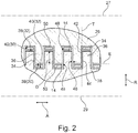
- Fig. 2 shows a schematically simplified detailed view of the two rollers 26, 28 of the separating device 12 in the effective area of the two rollers 26, 28.
- Fig. 2 is a representation in a sectional plane in which the axes of rotation 27, 29 of the rollers 26, 28 lie. The axes of rotation 27, 29 of the rollers 26, 28 extend in the axial direction A.
- the first roller 26 has a first circumferential surface 30 and the second roller 28 has a second circumferential surface 32.
- the circumferential surfaces 30, 32 of the rollers 26, 28 alternately have circumferential grooves 34 and blades 36 in the axial direction A. For reasons of clarity, only some of the grooves 34 and the blades 36 are provided with reference numerals. In the effective area of the two rollers 26, 28 shown, the blades 36 of the first roller 26 engage in the grooves 34 in FIG second roller 28 and the blades 36 of the second roller 28 engage in the grooves 34 of the first roller 26.
- the parting plane T lies in the representation of Fig. 2 perpendicular to the web plane E, in which the flat web 6 is fed to the separating device 12.
- the blades 36 of the rollers 26, 28 each comprise an upper side 38, which is part of the outer surface 30, 32 of the associated roller 26, 28.
- the grooves 34 each comprise a bottom 40, which is also part of the outer surface 30, 32 of the associated roller 26, 28.
- the blades 36 and the grooves 34 are connected to one another by flanks 42, 44.
- flanks 42 Depending on whether the grooves 34 or the blades 36 are assigned to the first or the second roller 26, 28, these flanks should be used as the first flanks 42 if the first roller 26 is concerned and as the second flanks 44 if they are is the second roller 28 are referred to.
- the flanks 42, 44 run radially, that is to say in a radial direction R, which is perpendicular to the axial direction A.
- the radial direction R runs in the direction of a radius of the respective roller 26, 28.
- the dividing lines along which the flat web 6 is divided into strips 14 each run between the first flanks 42 of the first roller 26 and the second flanks 44 of the second roller 28 .
- the separating device 12 is set up for separating the flat web 6, which has a predetermined material thickness.
- the separating device 12 can be designed in such a way that an axial gap dimension 46 is provided between the flanks 42, 44 of opposing rollers 26, 28, that is to say between the first flank 42 and the second flank 44, which is 0.5 times to twice, is in particular 0.6 times to 1 times the value of the predetermined material thickness of the flat web 6.
- a distance D measured in the radial direction R of the rollers 26, 28 between the The top side 38 of the blades 36 and the first roller 26 and the top side 38 of the blades 36 of the second roller 28 is, for example, one to five times the value of the predetermined material thickness of the flat web 6.
- the local expansion of the flat web 6 along the dividing lines leads to the fact that in the grooves 34 of the rollers 26, 28, the individual strips 14, of which only a few are provided with reference numerals for reasons of clarity, are present separately from one another.
- the strips 14 have an open structure at their edges 48, since they are not separated by a cut, but are torn apart in a defined manner by overextension.
- the separating device 12 comprises the deflecting device 13, which comprises at least one deflecting element, the webs 50 of which engage in the grooves 34 of the first and second rollers 26, 28.
- the webs 50 extend between the bottom 40 of the grooves 34 and the respective strip 14. The strips 14 are led out of the grooves 34 by the webs 50 at the end of the effective area, i.e.
- the strips 14 are led out of a cylindrical surface of the rollers 26, 28 defined by the outer circumferences of the blades 36.
- the strips 14 continue to reach a plate-shaped deflector of the deflector element, which is arranged downstream of the effective area and is designed as a closed surface.
- Fig. 3 shows a schematically simplified perspective illustration of the separating device 12, comprising the first roller 26 and the second roller 28.
- the flat web 6 is the separating device 12 from the right Side fed an inlet area 60.
- the deflecting device 13 comprises a first deflecting element 54 and a second deflecting element 56.
- the deflecting elements 54, 56 are designed in sections as plate-shaped deflectors.
- the deflecting elements 54, 56 are arranged symmetrically with respect to a separation plane AT. Their location is in Fig. 3 indicated with a dotted line.
- the deflecting elements 54, 56 are also configured symmetrically to the separation plane AT in the inlet area 60 and also in the outlet area 58, that is to say upstream of the effective area 52 and downstream of the effective area 52.
- the deflecting elements 54, 56 are configured identically in the inlet area 60 and in the outlet area 58.
- Fig. 3 the area of the second deflecting element 56 designed as a plate-shaped deflector 62 is visible in the outlet area 58.
- This plate-shaped deflector 62 is designed as a closed surface and connects the in Fig. 3 Non-visible webs 50 of the second deflector element 56 with one another.
- the deflecting elements 54, 56 are set up, for example, to exert a spring force acting in the direction of a separation plane AT on the flat web 6 or the strips 14 produced.
- the deflection elements 54, 56 are designed, for example, as spring-elastic elements.
- the bearings or suspension 63 of the deflecting elements 54, 56 are designed as spring bearings.
- the first deflecting element 54 therefore exerts a spring force in the direction of the second roller 28 or is spring-loaded in this direction.
- the second deflecting element 56 exerts a spring force in the direction of the first roller 26 or is spring-loaded in this direction.
- the spring force can be adjustable in each case.
- the deflecting elements 54, 56 are mechanically coupled to at least one vibration exciter. This is set up to set the deflector element 54, 56 in periodic or aperiodic oscillation.
- at least one suspension 63 of at least one deflecting element 54, 56 is designed as a vibration exciter, for example as a piezo actuator, eccentric, ultrasonic generator or as a mechanical element rotating with imbalance.
- the separating device 12 is also provided with a stripping device 64.
- This comprises a first comb-shaped scraper 66, which is provided with a plurality of prongs, the prongs of the first scraper 66 engaging in the grooves 34 of the first roller 26 and serving to clean the first roller 26.
- the stripping device 64 further comprises a second stripper 68, which is also provided with prongs, the prongs of the second stripper 68 engaging in the grooves 34 of this roller 28 to clean the second roller 28.
- the stripping device 64 further comprises a suction device 70 with which the particles removed from the rollers 26, 28 by the strippers 66, 68 are suctioned off.
- the suction device 70 each includes a hood 72, in which a suction channel 74 is provided.
- the hood 72 extends up to an outer surface of the rollers 26, 28, so that particles removed from the wipers 66, 68 are taken up into the interior of the hood 72 and removed via the suction channel 74.
- the first cutting roller 26 or the second cutting roller 28 or both cutting rollers 26, 28, ie the first cutting roller 26 and the second cutting roller 28, are designed, for example, as an intermittent roller (s).
- the design of the separating device 12 with at least one intermittent roller ensures that the strips 14 are connected in pairs to each other with crossbars.
- all of the blades 36 of the intermittent roller 26, 28 are each provided with a recess which interrupts a cutting edge of the blade 36.
- the recesses in the blades 36 of such an intermittent roller 26, 28 are arranged along a helix. This helix lies in a cylinder jacket spanned by the cutting edges of the blades 36. The axis of this helix coincides with the respective axis of rotation 27, 29 of the intermittent roller 26, 28.
- Fig. 4 shows the first roller 26 and the second roller 28 in a schematically simplified perspective detail view.
- An outer blade 36 of the first roller 26 is visible in the figure. In the effective area 52, this blade 36 overlaps with a blade 36 of the second roller 28. The blade 36 thus engages in a groove 34 in the roller 26, 28 opposite.
- the web 50 of the second deflector element 56 extends through this groove 34.
- An opposing first deflector element 54 also has webs 50, of which only a single one is partially visible. These extend through the grooves 34 of the first roller 26.
- the flat web 6 is fed from the right side between the first deflecting element 54 and the second deflecting element 56 to the effective area 52.
- the flat web 6 is separated into individual strips 14, which are led out of the roller 26, 28 on the upper side 76 of the webs 50 facing the respective opposite roller 26, 28.
- the strips 14 then reach the plate-shaped deflector 62, which is shown in FIG Fig. 4 is provided with reference numerals for the second deflector element 56.
- the strips 14 are guided on the top of the deflector 62 and further processing steps are provided.
- the strips 14 are also led out of the first roller 26 by the first deflector element 54.
- the strips 14 are guided between the two deflection elements 54, 56, more precisely between the plate-shaped deflectors 62 of the respective deflection elements 54, 56.
- Fig. 5 shows a schematic and simplified plan view of a deflecting element, for example the first deflecting element 54, the deflecting device 13.
- the deflecting element 54 comprises a multiplicity of webs 50. Between the webs 50 there are free spaces or slots through which the blades 36 of the first roller 26 in protrude ready for installation. The webs 50 merge into the plate-shaped deflector 62. An expansion 78 of the plate-shaped deflector 62 in the axial direction A is larger than a dimension of the effective area 52 in this direction. The dimension of the effective area 52 in the axial direction A corresponds to the distance between the outer blades 36 of the rollers 26, 28. Since the blades 36 of the roller 26 protrude through the slots between the webs 50, this is the distance between the outer edges of the outermost slots, measured in the axial direction A.
- the deflector 54 is, for example, made in one piece.
- a plate is provided with slots, for example, so that the webs 50 are formed.
- the deflector element 54 is thus completely flat, for example.
- Fig. 6 shows a schematically simplified perspective detail view of a one-piece deflector element 54 in the operating position.
- the opposite roller 28 cooperating with the roller 26 shown is not shown.
- the deflector element shown should again be the first deflector element 54.
- the blades 36 of the first roller 26 extend in the grooves between the webs 50.
- the webs 50 merge into the plate-shaped deflector 62.
- the plate-shaped deflector 62 adjoins the webs 50 downstream and connects all the webs 50 to one another.
- the webs 50 are also connected to one another upstream with a further plate-shaped deflector 80.
- Fig. 7 shows in a schematically simplified sectional view, which lies in a plane perpendicular to the axial direction A, the first roller 26 and the second roller 28. Also shown are the first deflecting element 54 and the second deflecting element 56, which together form the deflecting device 13.
- the two deflecting elements 54, 56 are arranged on opposite sides of the splitting plane AT.
- the splitting plane AT is arranged such that it is perpendicular to a shortest connection between a first axis of rotation 27 of the first roller 26 and a second axis of rotation 29 of the second roller 28.
- the AT separation level separates this shortest connection exactly in the middle.
- the splitting plane AT is thus equidistant from the first and second axes of rotation 27, 29. This applies provided that the two rollers 26, 28 have radii of the same size.
- the two deflecting elements 54, 56 are arranged, for example, mirror-symmetrically to the splitting plane AT.
- Fig. 8 again shows the schematically simplified perspective detail view of the first roller 26 and the second roller 28, the second roller 28 being designed, for example, with a second deflecting element 56 according to a further exemplary embodiment.
- the webs 50 are on the in the Fig. 8 front side received in a common bracket 82. In particular, it is provided that the webs 50 are not formed in one piece or in one piece with this holder 82.
- the webs 50 also each have an S-lay, so that their top 76 reduces the distance to the opposite roller, in this case the first roller 26, in some areas. The S-lay is directed in the direction of this first roller 26.
- Fig. 9 shows a further schematically simplified perspective view, in which the second roller 28 and a second deflecting element 56 are shown according to a further exemplary embodiment.
- the deflector element 56 has a first S-stroke in a first area 84 and a second S-stroke in a second area 86.
- Fig. 10 shows that out Fig. 9 known roller 28 including the second deflector 56 in a sectional view, shown in one plane perpendicular to the axial direction A.
- the first and second regions 84, 86 are visible, in which the S-strokes, which are pronounced in opposite directions, are present in the deflecting element 56.
- Fig. 11 shows in a further schematic and simplified perspective view the rollers 26, 28 of the separating device 13, each with a deflector 54, 56 according to a further embodiment.
- the deflecting elements 54, 56 are designed in such a way that they each have two S-blows directed in the opposite direction. These are present in the first and second areas 84, 86.
- a recess is provided in a third area 88, in which the deflector 54, 56 again moves away from the respective opposite roller 26, 28.
- Fig. 12 shows a further schematically simplified sectional illustration in a plane perpendicular to the axial direction A of the two rollers 26, 28 of the separating device 12.
- the illustrated separating device 12 comprises a deflecting device 13, comprising a first deflecting element 54 and a second deflecting element 56.
- Deviating from the previous exemplary embodiments Deflection devices 13 are the webs 50 of the in Fig. 12
- the deflector elements 54, 56 shown are each held on one side on the plate-shaped deflector 62 and extend from this into the grooves 34 of the first roller 26 or into the grooves 34 of the second roller 28.
- a web 50 is completely visible from the first deflecting element 54, since the sectional illustration in FIG Fig. 12 the view of a groove 34 of the first roller 26 releases.
- this web 50 extends in the direction of its free end 90 into the groove 34.
- the web 50 of the second deflecting element 56 is only partially visible, since the associated groove of the second roller 28 is shown in the sectional view of FIG Fig. 12 is not shown.
- the outlet zone between the deflection elements 54, 56 widens in a funnel shape.
- the plate-shaped deflector 62 of the second deflector element 56 is in particular flat and, for example, parallel to the dividing plane AT indicated in dotted line.
- the individual strips can be led out of the effective area between the rollers 26, 28 via the webs 50 and the plate-shaped deflector 62 of the second deflector element 56.
- FIG Fig. 12 shown on the first roller 26.
- Fig. 13 shows a further schematically simplified detailed view of the rollers 26, 28 of the separating device 12. An effective area is shown between the two rollers 26, 28 in a sectional plane in which the axes of rotation of the rollers 26, 28 lie. The representation is similar to that in Fig. 2 .
- the first roller 26 and the second roller 28 are only shown in sections.
- the blades 36 of the first roller 26 engage in grooves 34 of the second roller 28.
- the blades 36 of the second roller 28 conversely engage in the grooves 34 of the first roller 26.
- the webs 50 of the first deflecting element 54 are also each shown in cross section.
- the webs 50 of the second deflecting element 56 are arranged in the grooves 34 of the second roller 28 and shown in cross section.
- the webs 50 are T-shaped in cross section.
- a flat top 92 of the webs 50 faces the parting plane AT.
- the in Fig. 13 Strip 14, not shown, is led out of the effective area between the first and the second roller 26, 28.
- the webs 50 only fill the grooves 34 approximately in width in a head region 94. In a much narrower fuselage area 96, the width of the webs 50 is significantly smaller. It is thus possible for contaminants to be transported between the groove flanks 98 and the narrow trunk area 96 in the direction of the bottom 40 of the grooves 34, where they can be Fig. 13 Stripping device 64, not shown, can be removed.
Priority Applications (1)
| Application Number | Priority Date | Filing Date | Title |
|---|---|---|---|
| EP23184847.4A EP4241941A3 (fr) | 2019-01-14 | 2020-01-08 | Dispositif et procédé de fabrication d'un boudin de l'industrie de traitement du tabac |
Applications Claiming Priority (1)
| Application Number | Priority Date | Filing Date | Title |
|---|---|---|---|
| DE102019100755.0A DE102019100755A1 (de) | 2019-01-14 | 2019-01-14 | Vorrichtung und Verfahren zum Auftrennen einer Flachbahn sowie Vorrichtung zum Herstellen eines Strangs |
Related Child Applications (1)
| Application Number | Title | Priority Date | Filing Date |
|---|---|---|---|
| EP23184847.4A Division EP4241941A3 (fr) | 2019-01-14 | 2020-01-08 | Dispositif et procédé de fabrication d'un boudin de l'industrie de traitement du tabac |
Publications (2)
| Publication Number | Publication Date |
|---|---|
| EP3680078A1 true EP3680078A1 (fr) | 2020-07-15 |
| EP3680078B1 EP3680078B1 (fr) | 2023-07-12 |
Family
ID=69147521
Family Applications (2)
| Application Number | Title | Priority Date | Filing Date |
|---|---|---|---|
| EP23184847.4A Pending EP4241941A3 (fr) | 2019-01-14 | 2020-01-08 | Dispositif et procédé de fabrication d'un boudin de l'industrie de traitement du tabac |
| EP20150666.4A Active EP3680078B1 (fr) | 2019-01-14 | 2020-01-08 | Dispositif et procede de fabrication d'un fil pour l'industrie du tabac |
Family Applications Before (1)
| Application Number | Title | Priority Date | Filing Date |
|---|---|---|---|
| EP23184847.4A Pending EP4241941A3 (fr) | 2019-01-14 | 2020-01-08 | Dispositif et procédé de fabrication d'un boudin de l'industrie de traitement du tabac |
Country Status (4)
| Country | Link |
|---|---|
| EP (2) | EP4241941A3 (fr) |
| CN (1) | CN111434249B (fr) |
| DE (1) | DE102019100755A1 (fr) |
| PL (1) | PL3680078T3 (fr) |
Citations (8)
| Publication number | Priority date | Publication date | Assignee | Title |
|---|---|---|---|---|
| US789465A (en) | 1903-05-15 | 1905-05-09 | Varley Duplex Magnet Co | Paper-slitting machine. |
| US3472236A (en) | 1964-11-16 | 1969-10-14 | American Mach & Foundry | Cigarette or cigar making machine and method |
| DE1954036A1 (de) | 1968-10-28 | 1970-05-14 | American Mach & Foundry | Verfahren und Vorrichtung zur Herstellung von Zigaretten |
| DE3616554A1 (de) * | 1986-05-16 | 1987-11-19 | Schleicher Co Feinwerktech | Messerwalzen-abstreifvorrichtung fuer aktenvernichter oder dgl. |
| US5025814A (en) | 1987-05-12 | 1991-06-25 | R. J. Reynolds Tobacco Company | Cigarette filters containing strands of tobacco-containing materials |
| US5511732A (en) | 1994-12-28 | 1996-04-30 | Fellowes Manufacturing Company | Document shredding machine with continuous stripper |
| DE202011003744U1 (de) * | 2011-03-10 | 2011-05-12 | Su, Chao-Lung | Verstärkte Schneideinrichtung für einen Streifenschnitt-Aktenvernichter |
| CN108081344A (zh) * | 2017-11-23 | 2018-05-29 | 广东恒联食品机械有限公司 | 一种肉片切花机 |
Family Cites Families (2)
| Publication number | Priority date | Publication date | Assignee | Title |
|---|---|---|---|---|
| DE102007059625B4 (de) * | 2007-12-10 | 2013-07-25 | Hauni Maschinenbau Ag | Strangschneidvorrichtung |
| DE102016112724B4 (de) * | 2016-07-12 | 2018-02-08 | Hauni Maschinenbau Gmbh | Schneiden eines Belagpapierstreifens der Tabak verarbeitenden Industrie |
-
2019
- 2019-01-14 DE DE102019100755.0A patent/DE102019100755A1/de active Pending
-
2020
- 2020-01-08 PL PL20150666.4T patent/PL3680078T3/pl unknown
- 2020-01-08 EP EP23184847.4A patent/EP4241941A3/fr active Pending
- 2020-01-08 EP EP20150666.4A patent/EP3680078B1/fr active Active
- 2020-01-14 CN CN202010036841.3A patent/CN111434249B/zh active Active
Patent Citations (8)
| Publication number | Priority date | Publication date | Assignee | Title |
|---|---|---|---|---|
| US789465A (en) | 1903-05-15 | 1905-05-09 | Varley Duplex Magnet Co | Paper-slitting machine. |
| US3472236A (en) | 1964-11-16 | 1969-10-14 | American Mach & Foundry | Cigarette or cigar making machine and method |
| DE1954036A1 (de) | 1968-10-28 | 1970-05-14 | American Mach & Foundry | Verfahren und Vorrichtung zur Herstellung von Zigaretten |
| DE3616554A1 (de) * | 1986-05-16 | 1987-11-19 | Schleicher Co Feinwerktech | Messerwalzen-abstreifvorrichtung fuer aktenvernichter oder dgl. |
| US5025814A (en) | 1987-05-12 | 1991-06-25 | R. J. Reynolds Tobacco Company | Cigarette filters containing strands of tobacco-containing materials |
| US5511732A (en) | 1994-12-28 | 1996-04-30 | Fellowes Manufacturing Company | Document shredding machine with continuous stripper |
| DE202011003744U1 (de) * | 2011-03-10 | 2011-05-12 | Su, Chao-Lung | Verstärkte Schneideinrichtung für einen Streifenschnitt-Aktenvernichter |
| CN108081344A (zh) * | 2017-11-23 | 2018-05-29 | 广东恒联食品机械有限公司 | 一种肉片切花机 |
Also Published As
| Publication number | Publication date |
|---|---|
| EP3680078B1 (fr) | 2023-07-12 |
| PL3680078T3 (pl) | 2024-01-03 |
| CN111434249A (zh) | 2020-07-21 |
| EP4241941A3 (fr) | 2023-12-20 |
| EP4241941A2 (fr) | 2023-09-13 |
| DE102019100755A1 (de) | 2020-07-16 |
| CN111434249B (zh) | 2023-06-30 |
Similar Documents
| Publication | Publication Date | Title |
|---|---|---|
| EP3069834B1 (fr) | Dispositif de séparation d'un tronçon d'une masse alimentaire pâteuse | |
| EP0340619A1 (fr) | Dispositif de fabrication de métal étiré | |
| EP3880399A1 (fr) | Procédé pour la découpe d'un matériau d'électrode de batterie continu pour fabriquer des électrodes de batterie et électrode de batterie | |
| EP3542648B1 (fr) | Dispositif et procédé de fabrication d'un boudin d'une matière en bande | |
| EP1010503A2 (fr) | Dispositif de coupe ayant un premier et un deuxième alignement d'outils pouvant se déplacer l'un vis-à-vis de l'autre le long de directions parallèles | |
| DE102018103294B3 (de) | Vorrichtung zur Längstrennung eines Rohres | |
| EP3144133A1 (fr) | Dispositif destine au rainurage de feuilles de materiau | |
| AT501246B1 (de) | Vorrichtung und verfahren zum auftrennen einer bewegten materialbahn | |
| EP3680078B1 (fr) | Dispositif et procede de fabrication d'un fil pour l'industrie du tabac | |
| WO2020120579A1 (fr) | Dispositif avec dispositif de coupe à longueur de type guillotine pour la fabrication d'un produit en matériau d'emballage à partir d'une matière première fibreuse et procédé de fabrication d'un produit en matériau d'emballage | |
| DE102019116263A1 (de) | Einrichtung mit einer Mehrfach-Strangbildungsvorrichtung und Verfahren der Tabak verarbeitenden Industrie | |
| EP3849318A1 (fr) | Organe de moulage de ruban de pâte pourvue d'un dispositif de coupe | |
| DE2812354A1 (de) | Bewehrungsfasern sowie verfahren und vorrichtung zu ihrer herstellung | |
| EP1614353A1 (fr) | Dispositif pour alimenter et former une masse de confiserie plastiquement déformable | |
| EP1449958B1 (fr) | Dispositif pour traiter en particulier pour traiter par dépression, la toile de fabrication ou le feutre d'une machine à papier | |
| EP3829838A1 (fr) | Dispositif de séparation et procédé de séparation d'une bande plate en une pluralité de rubans reliés, ainsi que dispositif et procédé de fabrication d'un brin | |
| WO2007006362A1 (fr) | Dispositif pour une machine de l'industrie du tabac | |
| EP3598904B1 (fr) | Machine de l'industrie de transformation du tabac destinée au chargement d'une machine à boudins ainsi que procédé de fonctionnement d'une telle machine | |
| EP0939592A1 (fr) | Dispositif de mise en forme de pate | |
| DE19852562C1 (de) | Schmutzausscheider | |
| DE102009021808B4 (de) | Umlenkeinrichtung für Filtertow | |
| WO2024051944A1 (fr) | Procede et dispositif de nettoyage de la surface d'un fil metallique ou d'une bande metallique | |
| DE102021118030A1 (de) | Verfahren zur Herstellung eines gerafften Materials | |
| WO2021121774A1 (fr) | Procédé de coupe transversale d'une bande de matériau et dispositif associé | |
| AT409834B (de) | Verfahren und vorrichtung zum fortlaufenden schneiden von käsebahnen |
Legal Events
| Date | Code | Title | Description |
|---|---|---|---|
| PUAI | Public reference made under article 153(3) epc to a published international application that has entered the european phase |
Free format text: ORIGINAL CODE: 0009012 |
|
| STAA | Information on the status of an ep patent application or granted ep patent |
Free format text: STATUS: THE APPLICATION HAS BEEN PUBLISHED |
|
| AK | Designated contracting states |
Kind code of ref document: A1 Designated state(s): AL AT BE BG CH CY CZ DE DK EE ES FI FR GB GR HR HU IE IS IT LI LT LU LV MC MK MT NL NO PL PT RO RS SE SI SK SM TR |
|
| AX | Request for extension of the european patent |
Extension state: BA ME |
|
| STAA | Information on the status of an ep patent application or granted ep patent |
Free format text: STATUS: REQUEST FOR EXAMINATION WAS MADE |
|
| 17P | Request for examination filed |
Effective date: 20201217 |
|
| RBV | Designated contracting states (corrected) |
Designated state(s): AL AT BE BG CH CY CZ DE DK EE ES FI FR GB GR HR HU IE IS IT LI LT LU LV MC MK MT NL NO PL PT RO RS SE SI SK SM TR |
|
| STAA | Information on the status of an ep patent application or granted ep patent |
Free format text: STATUS: EXAMINATION IS IN PROGRESS |
|
| 17Q | First examination report despatched |
Effective date: 20210712 |
|
| RAP3 | Party data changed (applicant data changed or rights of an application transferred) |
Owner name: KOERBER TECHNOLOGIES GMBH |
|
| GRAP | Despatch of communication of intention to grant a patent |
Free format text: ORIGINAL CODE: EPIDOSNIGR1 |
|
| STAA | Information on the status of an ep patent application or granted ep patent |
Free format text: STATUS: GRANT OF PATENT IS INTENDED |
|
| INTG | Intention to grant announced |
Effective date: 20230301 |
|
| TPAC | Observations filed by third parties |
Free format text: ORIGINAL CODE: EPIDOSNTIPA |
|
| GRAS | Grant fee paid |
Free format text: ORIGINAL CODE: EPIDOSNIGR3 |
|
| GRAA | (expected) grant |
Free format text: ORIGINAL CODE: 0009210 |
|
| STAA | Information on the status of an ep patent application or granted ep patent |
Free format text: STATUS: THE PATENT HAS BEEN GRANTED |
|
| AK | Designated contracting states |
Kind code of ref document: B1 Designated state(s): AL AT BE BG CH CY CZ DE DK EE ES FI FR GB GR HR HU IE IS IT LI LT LU LV MC MK MT NL NO PL PT RO RS SE SI SK SM TR |
|
| REG | Reference to a national code |
Ref country code: CH Ref legal event code: EP |
|
| REG | Reference to a national code |
Ref country code: IE Ref legal event code: FG4D Free format text: LANGUAGE OF EP DOCUMENT: GERMAN |
|
| REG | Reference to a national code |
Ref country code: DE Ref legal event code: R096 Ref document number: 502020004081 Country of ref document: DE |
|
| P01 | Opt-out of the competence of the unified patent court (upc) registered |
Effective date: 20231001 |
|
| REG | Reference to a national code |
Ref country code: LT Ref legal event code: MG9D |
|
| REG | Reference to a national code |
Ref country code: NL Ref legal event code: MP Effective date: 20230712 |
|
| PG25 | Lapsed in a contracting state [announced via postgrant information from national office to epo] |
Ref country code: NL Free format text: LAPSE BECAUSE OF FAILURE TO SUBMIT A TRANSLATION OF THE DESCRIPTION OR TO PAY THE FEE WITHIN THE PRESCRIBED TIME-LIMIT Effective date: 20230712 |
|
| PG25 | Lapsed in a contracting state [announced via postgrant information from national office to epo] |
Ref country code: GR Free format text: LAPSE BECAUSE OF FAILURE TO SUBMIT A TRANSLATION OF THE DESCRIPTION OR TO PAY THE FEE WITHIN THE PRESCRIBED TIME-LIMIT Effective date: 20231013 |
|
| PG25 | Lapsed in a contracting state [announced via postgrant information from national office to epo] |
Ref country code: ES Free format text: LAPSE BECAUSE OF FAILURE TO SUBMIT A TRANSLATION OF THE DESCRIPTION OR TO PAY THE FEE WITHIN THE PRESCRIBED TIME-LIMIT Effective date: 20230712 |
|
| PG25 | Lapsed in a contracting state [announced via postgrant information from national office to epo] |
Ref country code: IS Free format text: LAPSE BECAUSE OF FAILURE TO SUBMIT A TRANSLATION OF THE DESCRIPTION OR TO PAY THE FEE WITHIN THE PRESCRIBED TIME-LIMIT Effective date: 20231112 |
|
| PG25 | Lapsed in a contracting state [announced via postgrant information from national office to epo] |
Ref country code: SE Free format text: LAPSE BECAUSE OF FAILURE TO SUBMIT A TRANSLATION OF THE DESCRIPTION OR TO PAY THE FEE WITHIN THE PRESCRIBED TIME-LIMIT Effective date: 20230712 Ref country code: RS Free format text: LAPSE BECAUSE OF FAILURE TO SUBMIT A TRANSLATION OF THE DESCRIPTION OR TO PAY THE FEE WITHIN THE PRESCRIBED TIME-LIMIT Effective date: 20230712 Ref country code: PT Free format text: LAPSE BECAUSE OF FAILURE TO SUBMIT A TRANSLATION OF THE DESCRIPTION OR TO PAY THE FEE WITHIN THE PRESCRIBED TIME-LIMIT Effective date: 20231113 Ref country code: NO Free format text: LAPSE BECAUSE OF FAILURE TO SUBMIT A TRANSLATION OF THE DESCRIPTION OR TO PAY THE FEE WITHIN THE PRESCRIBED TIME-LIMIT Effective date: 20231012 Ref country code: LV Free format text: LAPSE BECAUSE OF FAILURE TO SUBMIT A TRANSLATION OF THE DESCRIPTION OR TO PAY THE FEE WITHIN THE PRESCRIBED TIME-LIMIT Effective date: 20230712 Ref country code: LT Free format text: LAPSE BECAUSE OF FAILURE TO SUBMIT A TRANSLATION OF THE DESCRIPTION OR TO PAY THE FEE WITHIN THE PRESCRIBED TIME-LIMIT Effective date: 20230712 Ref country code: IS Free format text: LAPSE BECAUSE OF FAILURE TO SUBMIT A TRANSLATION OF THE DESCRIPTION OR TO PAY THE FEE WITHIN THE PRESCRIBED TIME-LIMIT Effective date: 20231112 Ref country code: HR Free format text: LAPSE BECAUSE OF FAILURE TO SUBMIT A TRANSLATION OF THE DESCRIPTION OR TO PAY THE FEE WITHIN THE PRESCRIBED TIME-LIMIT Effective date: 20230712 Ref country code: GR Free format text: LAPSE BECAUSE OF FAILURE TO SUBMIT A TRANSLATION OF THE DESCRIPTION OR TO PAY THE FEE WITHIN THE PRESCRIBED TIME-LIMIT Effective date: 20231013 Ref country code: FI Free format text: LAPSE BECAUSE OF FAILURE TO SUBMIT A TRANSLATION OF THE DESCRIPTION OR TO PAY THE FEE WITHIN THE PRESCRIBED TIME-LIMIT Effective date: 20230712 Ref country code: ES Free format text: LAPSE BECAUSE OF FAILURE TO SUBMIT A TRANSLATION OF THE DESCRIPTION OR TO PAY THE FEE WITHIN THE PRESCRIBED TIME-LIMIT Effective date: 20230712 |
|
| PGFP | Annual fee paid to national office [announced via postgrant information from national office to epo] |
Ref country code: PL Payment date: 20231215 Year of fee payment: 5 |
|
| REG | Reference to a national code |
Ref country code: DE Ref legal event code: R026 Ref document number: 502020004081 Country of ref document: DE |
|
| PLBI | Opposition filed |
Free format text: ORIGINAL CODE: 0009260 |
|
| PG25 | Lapsed in a contracting state [announced via postgrant information from national office to epo] |
Ref country code: SM Free format text: LAPSE BECAUSE OF FAILURE TO SUBMIT A TRANSLATION OF THE DESCRIPTION OR TO PAY THE FEE WITHIN THE PRESCRIBED TIME-LIMIT Effective date: 20230712 Ref country code: RO Free format text: LAPSE BECAUSE OF FAILURE TO SUBMIT A TRANSLATION OF THE DESCRIPTION OR TO PAY THE FEE WITHIN THE PRESCRIBED TIME-LIMIT Effective date: 20230712 Ref country code: EE Free format text: LAPSE BECAUSE OF FAILURE TO SUBMIT A TRANSLATION OF THE DESCRIPTION OR TO PAY THE FEE WITHIN THE PRESCRIBED TIME-LIMIT Effective date: 20230712 Ref country code: DK Free format text: LAPSE BECAUSE OF FAILURE TO SUBMIT A TRANSLATION OF THE DESCRIPTION OR TO PAY THE FEE WITHIN THE PRESCRIBED TIME-LIMIT Effective date: 20230712 Ref country code: CZ Free format text: LAPSE BECAUSE OF FAILURE TO SUBMIT A TRANSLATION OF THE DESCRIPTION OR TO PAY THE FEE WITHIN THE PRESCRIBED TIME-LIMIT Effective date: 20230712 Ref country code: SK Free format text: LAPSE BECAUSE OF FAILURE TO SUBMIT A TRANSLATION OF THE DESCRIPTION OR TO PAY THE FEE WITHIN THE PRESCRIBED TIME-LIMIT Effective date: 20230712 |
|
| PGFP | Annual fee paid to national office [announced via postgrant information from national office to epo] |
Ref country code: DE Payment date: 20240201 Year of fee payment: 5 |
|
| PLAX | Notice of opposition and request to file observation + time limit sent |
Free format text: ORIGINAL CODE: EPIDOSNOBS2 |