EP3680009B1 - Schurrenartiger monomerspender - Google Patents
Schurrenartiger monomerspender Download PDFInfo
- Publication number
- EP3680009B1 EP3680009B1 EP18865906.4A EP18865906A EP3680009B1 EP 3680009 B1 EP3680009 B1 EP 3680009B1 EP 18865906 A EP18865906 A EP 18865906A EP 3680009 B1 EP3680009 B1 EP 3680009B1
- Authority
- EP
- European Patent Office
- Prior art keywords
- dispenser
- monomer
- chute
- slanted
- polymerization apparatus
- Prior art date
- Legal status (The legal status is an assumption and is not a legal conclusion. Google has not performed a legal analysis and makes no representation as to the accuracy of the status listed.)
- Active
Links
Images




Classifications
-
- B—PERFORMING OPERATIONS; TRANSPORTING
- B01—PHYSICAL OR CHEMICAL PROCESSES OR APPARATUS IN GENERAL
- B01J—CHEMICAL OR PHYSICAL PROCESSES, e.g. CATALYSIS OR COLLOID CHEMISTRY; THEIR RELEVANT APPARATUS
- B01J4/00—Feed or outlet devices; Feed or outlet control devices
- B01J4/001—Feed or outlet devices as such, e.g. feeding tubes
- B01J4/005—Feed or outlet devices as such, e.g. feeding tubes provided with baffles
-
- B—PERFORMING OPERATIONS; TRANSPORTING
- B01—PHYSICAL OR CHEMICAL PROCESSES OR APPARATUS IN GENERAL
- B01J—CHEMICAL OR PHYSICAL PROCESSES, e.g. CATALYSIS OR COLLOID CHEMISTRY; THEIR RELEVANT APPARATUS
- B01J19/00—Chemical, physical or physico-chemical processes in general; Their relevant apparatus
- B01J19/0053—Details of the reactor
- B01J19/006—Baffles
-
- B—PERFORMING OPERATIONS; TRANSPORTING
- B01—PHYSICAL OR CHEMICAL PROCESSES OR APPARATUS IN GENERAL
- B01J—CHEMICAL OR PHYSICAL PROCESSES, e.g. CATALYSIS OR COLLOID CHEMISTRY; THEIR RELEVANT APPARATUS
- B01J19/00—Chemical, physical or physico-chemical processes in general; Their relevant apparatus
- B01J19/06—Solidifying liquids
-
- B—PERFORMING OPERATIONS; TRANSPORTING
- B01—PHYSICAL OR CHEMICAL PROCESSES OR APPARATUS IN GENERAL
- B01J—CHEMICAL OR PHYSICAL PROCESSES, e.g. CATALYSIS OR COLLOID CHEMISTRY; THEIR RELEVANT APPARATUS
- B01J19/00—Chemical, physical or physico-chemical processes in general; Their relevant apparatus
- B01J19/18—Stationary reactors having moving elements inside
- B01J19/22—Stationary reactors having moving elements inside in the form of endless belts
-
- B—PERFORMING OPERATIONS; TRANSPORTING
- B01—PHYSICAL OR CHEMICAL PROCESSES OR APPARATUS IN GENERAL
- B01J—CHEMICAL OR PHYSICAL PROCESSES, e.g. CATALYSIS OR COLLOID CHEMISTRY; THEIR RELEVANT APPARATUS
- B01J19/00—Chemical, physical or physico-chemical processes in general; Their relevant apparatus
- B01J19/26—Nozzle-type reactors, i.e. the distribution of the initial reactants within the reactor is effected by their introduction or injection through nozzles
-
- B—PERFORMING OPERATIONS; TRANSPORTING
- B01—PHYSICAL OR CHEMICAL PROCESSES OR APPARATUS IN GENERAL
- B01J—CHEMICAL OR PHYSICAL PROCESSES, e.g. CATALYSIS OR COLLOID CHEMISTRY; THEIR RELEVANT APPARATUS
- B01J4/00—Feed or outlet devices; Feed or outlet control devices
- B01J4/001—Feed or outlet devices as such, e.g. feeding tubes
- B01J4/002—Nozzle-type elements
-
- B—PERFORMING OPERATIONS; TRANSPORTING
- B01—PHYSICAL OR CHEMICAL PROCESSES OR APPARATUS IN GENERAL
- B01J—CHEMICAL OR PHYSICAL PROCESSES, e.g. CATALYSIS OR COLLOID CHEMISTRY; THEIR RELEVANT APPARATUS
- B01J4/00—Feed or outlet devices; Feed or outlet control devices
- B01J4/008—Feed or outlet control devices
-
- B—PERFORMING OPERATIONS; TRANSPORTING
- B05—SPRAYING OR ATOMISING IN GENERAL; APPLYING FLUENT MATERIALS TO SURFACES, IN GENERAL
- B05B—SPRAYING APPARATUS; ATOMISING APPARATUS; NOZZLES
- B05B15/00—Details of spraying plant or spraying apparatus not otherwise provided for; Accessories
- B05B15/50—Arrangements for cleaning; Arrangements for preventing deposits, drying-out or blockage; Arrangements for detecting improper discharge caused by the presence of foreign matter
Definitions
- the present invention relates to a chute type monomer dispenser capable of feeding a monomer without foreign substances.
- a super absorbent polymer is a synthetic polymer material having a function of absorbing about 500 to 1,000 times its own weight of moisture.
- SAM super absorbency material
- AGM absorbent gel material
- the super absorbent polymer started to be practically applied in sanitary products and is currently widely used for water retaining soil for gardening, water stop materials for civil engineering and construction, sheets for raising seedling, fresh-keeping agents for food distribution fields, and materials for poultices, as well as hygiene products such as disposable diapers for children.
- the reverse phase suspension polymerization method is disclosed in Japanese Patent Laid-Open Publication Nos. S56-161408 , S57-158209 , S57-198714 , and also in KR20150133142A , US4985518A , KR20110138962A , EP2787012A and US4389357A .
- aqueous solution polymerization method a thermal polymerization method of polymerizing a hydrous gel phase polymer while fracturing and cooling the hydrous gel phase polymer in a kneader equipped with a plurality of shafts, a photo-polymerization method of irradiating an aqueous solution having a high concentration with UV rays and the like on a belt to perform polymerization and drying at the same time, and the like have been known.
- a monomer is fed using a cylindrical dispenser including the belt type SAP polymerization apparatus with a vertical pipe to convey the monomer at a uniform speed and thickness.
- Such a cylindrical dispenser includes a main channel through which a monomer is moved and a plurality of discharge channels branched from the main channel and through which the monomer is discharged.
- the monomer may be fed to the belt type SAP polymerization apparatus in a state in which an initiator and a foaming agent are injected together and mixed with the monomer.
- the present invention has been made in an effort to provide a chute type monomer dispenser having advantages of preventing a belt of a polymerization apparatus from being damaged due to foreign substances by preventing a formation of a dead zone where a flow of a monomer is blocked during feeding the monomer.
- An exemplary embodiment of the present invention provides a chute type monomer dispenser including: a chute dispenser installed to be slanted in a direction of a polymerization apparatus, injecting a monomer to the polymerization apparatus through an injection pipe, and having an injection portion opened at an upper portion of the chute dispenser; and an injector injecting an initiator and a foaming agent to the injection portion.
- the chute dispenser includes a dispenser body on which the monomer is moved in the direction of the polymerization apparatus, and guide portions formed at sides of the dispenser body and guiding the movement of the monomer.
- the dispenser body has a slanted movement portion on which the monomer, the initiator, and the foaming agent are moved in the direction of the polymerization apparatus.
- the slanted movement portion is formed in a fan shaped plane suitable for feeding a monomer to the polymerization apparatus while maintaining a uniform thickness, and may be formed from a portion where the first guide protrusion and the second guide protrusion are connected to each other.
- the injection pipe may have an opened fan-shaped portion where the monomer is discharged to the injection portion.
- the injector may inject the initiator and the foaming agent to a portion of the injection portion of the chute dispenser in a spray manner.
- a time required for a monomer to move from an injected position to a discharged position and a flow rate of the monomer are further increased, such that the monomer is stably fed without generation of foreign substances, thereby preventing a belt of the polymerization apparatus from being damaged due to the foreign substances.
- FIG. 1 is a cross-sectional view schematically illustrating a chute type monomer dispenser according to an exemplary embodiment of the present invention
- FIG. 2 is a perspective view schematically illustrating an operation state of a chute dispenser and an injector of the chute type monomer dispenser according to an exemplary embodiment of the present invention
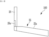
- FIG. 3 is a side view of the chute type monomer dispenser of FIG. 2 .
- a chute type monomer dispenser 100 includes a chute dispenser 20 installed to be slanted in a direction of a polymerization space inside a polymerization apparatus, injecting a monomer into the polymerization space through an injection pipe 26, and having an injection portion 22 formed at an upper portion of the chute dispenser, and an injector 30 injecting an initiator and a foaming agent to the injection portion 22.
- the polymerization apparatus 10 is for preparing a super absorbent polymer (SAP), and a belt type polymerization apparatus is described in the present exemplary embodiment by way of example.
- SAP super absorbent polymer
- the polymerization apparatus 10 may include a plurality of rotation shafts 11, a conveyer belt 13 movably installed in a certain direction between the rotation shafts 11, and a polymerization energy feeding unit 15 feeding polymerization energy.
- the monomer, the initiator, and the foaming agent may be injected to the polymerization apparatus 10.
- the monomer 21 may be injected to the polymerization apparatus 10 by the chute dispenser 20.
- the chute dispenser 20 is installed to be slanted in the direction of the polymerization apparatus and may inject the monomer to the polymerization apparatus.
- the chute dispenser 20 has an injection portion 22 opened at the upper portion of the chute dispenser, and the monomer 21 may be fed through the injection portion 22 and be injected into the polymerization apparatus 10.
- the monomer 21 may be fed into the injection portion 22 of the chute dispenser 20 through the injection pipe 26.
- the chute dispenser 20 includes a dispenser body 23 on which the monomer 21 is moved in the direction of the polymerization apparatus 10, and guide portions 25 formed at sides of the dispenser body 23 and guiding the movement of the monomer 21.
- the dispenser body 23 is installed to be slanted in the direction of the polymerization apparatus, and is installed so that the monomer 21 is injected into the polymerization apparatus 10 by its own weight.
- the dispenser body 23 has a slanted movement portion on which the monomer 21 is moved.
- the dispenser body and the slanted movement portion are denoted by the same reference numerals.
- the slanted movement portion 23 is formed at the upper portion of the dispenser body 23 and is formed in a fan-shaped plane with a long length in the present exemplary embodiment so that the monomer 21 is moved in the direction of the polymerization apparatus 10 by its own weight.
- the slanted movement portion 23 is formed in the fan-shaped plane, such that the monomer may be fed to the polymerization apparatus 10 while maintaining a uniform thickness, in a process in which the monomer 21 is discharged in the direction of the polymerization apparatus.
- the dispenser body 23 has guide portions 25 guiding the movement of the monomer 21.
- the guide portions 25 may include a first guide protrusion 25a protruding at an edge of a first side of the slanted movement portion 23 and a second guide protrusion 25b protruding at an edge of a second side of the slanted movement portion 23, the second side being opposed to the first side.
- the first guide protrusion 25a protrudes at the edge of the first side of the slanted movement portion 23, and may prevent the monomer 21 moved along the slanted movement portion 23 from escaping from the first side thereof to the outside.
- the first guide protrusion 25a may protrude at the first side of the slanted movement portion 23, while being in a slanted state.
- the first guide protrusion 25a may protrude in a slanted state so as to have a maximum height at a portion at which the monomer 21 is injected and a minimum height at a portion at which the monomer 21 is discharged, depending on a slant angle of the slanted movement portion 23.
- the second guide protrusion 25b may protrude at the second side of the slanted movement portion 23, while being in a slanted state.
- the second guide protrusion 25b is formed in the same size and shape as those of the first guide protrusion 25a, and may protrude at the second side opposed to the first side of the slanted movement portion 23.
- the second guide protrusion 25b may protrude at the second side of the slanted movement portion 23, while being in a slanted state.
- the second guide protrusion 25b may protrude in a slanted state so as to have a maximum height at a portion at which the monomer 21 is injected and a minimum height at a portion at which the monomer 21 is discharged, depending on a slant angle of the slanted movement portion 23.
- the second guide protrusion 25b protrudes at the second side of the slanted movement portion 23, and may prevent the monomer 21 from escaping from the second side of the slanted movement portion 23 to the outside in a process in which the monomer is injected.
- the first guide protrusion 25a and the second guide protrusion 25b described above each are formed in a protruding state at the edges of the both sides of the slanted movement portion 23 formed in a fan shape, such that the monomer 21 discharged along the slanted movement portion 23 may be guided to be stably injected to the polymerization apparatus 10 while maintaining a uniform thickness.
- FIG. 4 is a view schematically illustrating a state in which an injection pipe of the chute type monomer dispenser of FIG. 3 is installed
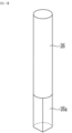
- FIG. 5 is a perspective view schematically illustrating the injection pipe according to an exemplary embodiment of the present invention.
- the monomer 21 may be injected into the injection portion 22 of the chute dispenser 20 through the injection pipe 26.
- the injection pipe 26 may have an opened fan-shaped portion 26a where the monomer 21 is discharged to the injection portion 22. More specifically, the injection pipe 26 may be installed in a state in which one side of an end of the injection pipe 26 is in contact with an inner surface of the first guide protrusion 25a and the other side of the end of the injection pipe 26 is in contact with an inner surface of the second guide protrusion 25b.
- the monomer 21 injected through the injection pipe 26 may be stably moved along the slanted movement portion 23 without a dead zone where a flow of the monomer is blocked.
- an initiator and a foaming agent 31 may be injected to the chute dispenser 20 by the injector 30.
- the injector 30 installed outside the chute dispenser 20 may be installed to inject the initiator and the foaming agent toward the injection portion 22 of the chute dispenser 20.
- the injector 30 may inject the initiator and the foaming agent toward the injection portion 22 from the outside of the chute dispenser 20 in a spray manner.
- the injector 30 injects the initiator and the foaming agent in a spray manner in a state in which the injector 30 is spaced apart from an upper side of the chute dispenser 20 at a predetermined distance to feed the initiator and the foaming agent to the chute dispenser 20.
- One injector 30 may be installed above the chute dispenser 20.
- injector 30 may be installed outside the chute dispenser 20 depending on injection amounts and injection positions of the initiator and the foaming agent.
- the chute type monomer dispenser 100 of the present exemplary embodiment may uniformly distribute and feed the monomer 21 fed through the vertical type injection pipe 26 to the belt type polymerization apparatus 10.
- the chute dispenser 20 is formed in an open type, and the initiator and the foaming agent may be fed to the open type chute dispenser 20 by the injector 30 in a spray manner.
- the monomer, the initiator, and the foaming agent fed to the chute dispenser 20 may be fed to the polymerization apparatus while turbulence for mixing is sufficiently formed.
- the chute dispenser 20 has the opened injection portion 22, such that the monomer, the initiator, and the foaming agent may be efficiently fed without a dead zone where a flow is blocked.
- FIG. 6 is a view schematically illustrating a state in which a dead zone is formed in a cylindrical dispenser according to the related art
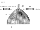
- FIG. 7 is a view schematically illustrating a state in which a dead zone is not formed in the chute type monomer dispenser according to an exemplary embodiment of the present invention.
- a wide dead zone is formed between a first outlet A and a second outlet B that are formed between an edge and an inlet of the cylindrical dispenser 1.
- a time required for a monomer to move from an injected position to a discharged position and a flow rate of the monomer are further increased, such that the monomer is stably fed without generation of foreign substances.
Landscapes
- Chemical & Material Sciences (AREA)
- Organic Chemistry (AREA)
- Chemical Kinetics & Catalysis (AREA)
- Polymerisation Methods In General (AREA)
- Compositions Of Macromolecular Compounds (AREA)
- Processing And Handling Of Plastics And Other Materials For Molding In General (AREA)
Claims (5)
- Tropfenartiger Monomerspender (100), umfassend:einen Tropfenspender (20), der so installiert ist, dass er in Richtung eines Förderbands (13) einer Polymerisationsvorrichtung (10) geneigt ist und einen Einspritzabschnitt (22) aufweist, der an einem oberen Abschnitt des Tropfenspenders (20) geöffnet ist;einen Injektor (30), der zum Einspritzen eines Initiators und eines Schaummittels in den Einspritzabschnitt geeignet ist,dadurch gekennzeichnet, dassder Tropfenspender (20) einen Spenderkörper (23) umfasst, der so installiert ist, dass er in Richtung eines Förderbands (13) der Polymerisationsvorrichtung (10) geneigt ist, so dass das Monomer (21) durch sein Eigengewicht in die Polymerisationsvorrichtung (10) eingespritzt wird, und einen geneigten Bewegungsabschnitt aufweist;der geneigte Bewegungsabschnitt in einer fächerförmigen Ebene ausgebildet ist, die zum Zuführen des Monomers (21) zur Polymerisationsvorrichtung (10) geeignet ist, während eine gleichmäßige Dicke beibehalten wird, in einem Prozess, in dem das Monomer (21) in Richtung der Polymerisationsvorrichtung (10) abgegeben wird; undder Spenderkörper (23) Führungsabschnitte (25) aufweist, die an Seiten des Spenderkörpers ausgebildet und konfiguriert sind, um die Bewegung des Monomers (21) zu führen.
- Tropfenartiger Monomerspender (100) nach Anspruch 1, bei dem
die Führungsabschnitte (25) umfassen:einen ersten Führungsvorsprung (25a), der an einer Kante einer ersten Seite des geneigten Bewegungsabschnitts (24) vorsteht; undeinen zweiten Führungsvorsprung (25b), der an einer Kante einer zweiten Seite des geneigten Bewegungsabschnitts (24) vorsteht, wobei die zweite Seite der ersten Seite gegenüberliegt. - Tropfenartiger Monomerspender (100) nach Anspruch 2, bei dem
der geneigte Bewegungsabschnitt (24) in einem fächerförmigen Abschnitt ausgebildet ist, wo der erste Führungsvorsprung (25a) und der zweite Führungsvorsprung (25b) miteinander verbunden sind. - Tropfenartiger Monomerspender (100) nach Anspruch 1, bei dem
das Einspritzrohr (26) einen geöffneten fächerförmigen Abschnitt aufweist, wo das Monomer zum Einspritzabschnitt (22) abgegeben wird. - Tropfenartiger Monomerspender (100) nach Anspruch 1, bei dem
der Injektor (30) zum Einspritzen des Initiators und des Schaummittels in einen Abschnitt des Einspritzabschnitts (22) des Tropfenspenders (20) auf Sprühweise geeignet ist.
Applications Claiming Priority (2)
| Application Number | Priority Date | Filing Date | Title |
|---|---|---|---|
| KR1020170132738A KR20190041308A (ko) | 2017-10-12 | 2017-10-12 | 슈트 타입 모노머 디스펜서 |
| PCT/KR2018/012054 WO2019074328A2 (ko) | 2017-10-12 | 2018-10-12 | 슈트 타입 모노머 디스펜서 |
Publications (3)
| Publication Number | Publication Date |
|---|---|
| EP3680009A2 EP3680009A2 (de) | 2020-07-15 |
| EP3680009A4 EP3680009A4 (de) | 2020-08-12 |
| EP3680009B1 true EP3680009B1 (de) | 2024-12-04 |
Family
ID=66100865
Family Applications (1)
| Application Number | Title | Priority Date | Filing Date |
|---|---|---|---|
| EP18865906.4A Active EP3680009B1 (de) | 2017-10-12 | 2018-10-12 | Schurrenartiger monomerspender |
Country Status (6)
| Country | Link |
|---|---|
| US (1) | US10967347B2 (de) |
| EP (1) | EP3680009B1 (de) |
| JP (1) | JP7022208B2 (de) |
| KR (2) | KR20190041308A (de) |
| CN (1) | CN111194238B (de) |
| WO (1) | WO2019074328A2 (de) |
Families Citing this family (2)
| Publication number | Priority date | Publication date | Assignee | Title |
|---|---|---|---|---|
| KR102860679B1 (ko) * | 2020-10-15 | 2025-09-15 | 주식회사 엘지화학 | 고흡수성 수지 제조용 중합 반응기 |
| KR102883894B1 (ko) * | 2020-10-23 | 2025-11-07 | 주식회사 엘지화학 | 고흡수성 수지 제조용 중합 반응기 |
Family Cites Families (20)
| Publication number | Priority date | Publication date | Assignee | Title |
|---|---|---|---|---|
| GB1551935A (en) | 1976-08-19 | 1979-09-05 | Philips Nv | Imaging devices |
| JPS56161408A (en) | 1980-05-19 | 1981-12-11 | Kao Corp | Production of water-absorbing resin |
| JPS57158209A (en) | 1981-03-25 | 1982-09-30 | Kao Corp | Production of bead-form highly water-absorbing polymer |
| JPS57198714A (en) | 1981-05-29 | 1982-12-06 | Sumitomo Chem Co Ltd | Production of hydrogel |
| US4389357A (en) * | 1981-06-26 | 1983-06-21 | Ashland Oil, Inc. | Method for preparing thermosetting resins |
| US4985518A (en) * | 1981-10-26 | 1991-01-15 | American Colloid Company | Process for preparing water-absorbing resins |
| JP4679683B2 (ja) * | 1999-11-02 | 2011-04-27 | 株式会社日本触媒 | 吸水性重合体の製造方法、及び該重合体の製造装置 |
| DE10060372A1 (de) | 2000-12-05 | 2002-06-06 | Basell Polyolefine Gmbh | Vorrichtung zur Initiatoreinspeisung an Reaktoren |
| WO2009077100A1 (de) | 2007-12-17 | 2009-06-25 | Basf Se | Verfahren zur herstellung wasserabsorbierender polymerpartikel |
| CN101884900A (zh) | 2009-05-15 | 2010-11-17 | 辽宁华兴集团化工股份公司 | 喷雾式反应器 |
| US20110160689A1 (en) * | 2009-12-30 | 2011-06-30 | Steven Ray Merrigan | High internal phase emulsion comprising photoinitiator |
| US8376663B2 (en) * | 2010-03-10 | 2013-02-19 | Mantissa Corporation | Segmented conveyor and air film chute |
| KR101126678B1 (ko) | 2010-06-22 | 2012-03-29 | 주식회사 엘지화학 | 고흡수성 수지 제조용 중합 반응기 및 이를 이용한 고흡수성 수지의 제조 방법 |
| EP2787012B1 (de) | 2012-04-13 | 2017-03-29 | LG Chem, Ltd. | Verfahren zur herstellung eines stark absorbierenden polymers |
| JP5496255B2 (ja) | 2012-05-31 | 2014-05-21 | 三菱電機株式会社 | 磁石式回転電機の回転子の製造方法およびその製造装置 |
| JP6204179B2 (ja) | 2012-12-13 | 2017-09-27 | 旭化成株式会社 | 重合反応装置 |
| KR101648138B1 (ko) * | 2014-05-19 | 2016-08-12 | 주식회사 엘지화학 | 고흡수성 수지 제조용 중합 반응기 및 이를 이용한 고흡수성 수지의 제조 방법 |
| US20160001315A1 (en) | 2014-07-03 | 2016-01-07 | Nch Corporation | System and Method for Conveying Low-Shear Tolerant Matrixes |
| KR101659347B1 (ko) | 2014-12-08 | 2016-09-23 | 주식회사 포스코 | 슈트의 부착탄 제거 장치 |
| CN106861558B (zh) | 2017-03-24 | 2019-09-27 | 广东洛斯特制药有限公司 | 苯扎氯铵单体合成装置 |
-
2017
- 2017-10-12 KR KR1020170132738A patent/KR20190041308A/ko not_active Ceased
-
2018
- 2018-10-12 JP JP2020520144A patent/JP7022208B2/ja active Active
- 2018-10-12 WO PCT/KR2018/012054 patent/WO2019074328A2/ko not_active Ceased
- 2018-10-12 CN CN201880065317.XA patent/CN111194238B/zh active Active
- 2018-10-12 EP EP18865906.4A patent/EP3680009B1/de active Active
- 2018-10-12 US US16/754,628 patent/US10967347B2/en active Active
-
2021
- 2021-06-25 KR KR1020210083262A patent/KR102299899B1/ko active Active
Also Published As
| Publication number | Publication date |
|---|---|
| WO2019074328A3 (ko) | 2019-06-06 |
| EP3680009A4 (de) | 2020-08-12 |
| JP7022208B2 (ja) | 2022-02-17 |
| EP3680009A2 (de) | 2020-07-15 |
| KR20190041308A (ko) | 2019-04-22 |
| JP2020537004A (ja) | 2020-12-17 |
| WO2019074328A2 (ko) | 2019-04-18 |
| CN111194238A (zh) | 2020-05-22 |
| CN111194238B (zh) | 2022-04-29 |
| US20210001295A1 (en) | 2021-01-07 |
| KR20210083234A (ko) | 2021-07-06 |
| KR102299899B1 (ko) | 2021-09-07 |
| US10967347B2 (en) | 2021-04-06 |
Similar Documents
| Publication | Publication Date | Title |
|---|---|---|
| EP3984711A1 (de) | Zusammengesetzter chopper für superabsorbierendes hydrogel | |
| US8907021B2 (en) | Polyacrylic acid (salt)-type water absorbent resin and method for producing of same | |
| DE69910884T2 (de) | Verfahren und Produktion von Absorptionharz aus Hydrogelformteilchen | |
| US10967347B2 (en) | Chute type monomer dispenser | |
| US6140395A (en) | Method of producing hydrophilic resin | |
| EP2808078A1 (de) | Polymerisationsreaktoren zur Herstellung eines superabsorbierenden Polymers sowie Hestellungsverfahren dafür mit diesen Reaktoren | |
| EP3318594A1 (de) | Verfahren zur herstellung eines supersaugfähigen harzes | |
| EP2270074A1 (de) | Oberflächenbehandlungsverfahren eines wasserabsorbierenden harzes und verfahren zur herstellung des wasserabsorbierenden harzes | |
| EP3070107A1 (de) | Verfahren zur herstellung eines superabsorbierenden polymers und auf diese weise hergestelltes superabsorbierendes polymer | |
| EP3719059B1 (de) | Verfahren zur herstellung eines stark absorbierenden polymers | |
| US20170114192A1 (en) | Surface cross-linked super absorbent resin and method for preparing same | |
| US20220212166A1 (en) | Preparation method of super absorbent polymer composition | |
| EP3112383A1 (de) | Verfahren zur herstellung eines supersaugfähigen harzes und anhand des verfahrens hergestelltes supersaugfähiges harz | |
| US12491662B2 (en) | Minute cutting apparatus for super absorbent polymer hydrogel using pump | |
| US20240110018A1 (en) | Preparation Method of Super Absorbent Polymer and Super Absorbent Polymer Therefrom | |
| EP3819329A1 (de) | Superabsorbierendes polymer und verfahren zur herstellung davon | |
| KR20250081347A (ko) | 초퍼용 홀 플레이트 및 이를 구비한 초퍼 | |
| US11066496B2 (en) | Super absorbent polymer and method for preparing same | |
| EP3995515A1 (de) | Vernetztes polymergel, verfahren zu seiner herstellung, monomerzusammensetzung und verfahren zur herstellung von vernetzten polymerteilchen | |
| EP2048463A1 (de) | Trocknung von wasserabweisendem pulver, produktionsverfahren und produktionsvorrichtung | |
| EP4269478A1 (de) | Verfahren zur herstellung eines superabsorbierenden polymers | |
| KR20190027682A (ko) | 정적 혼합기 및 이를 이용한 고흡수성 수지의 제조 방법 | |
| US20230287155A1 (en) | Method for preparing super absorbent polymer |
Legal Events
| Date | Code | Title | Description |
|---|---|---|---|
| STAA | Information on the status of an ep patent application or granted ep patent |
Free format text: STATUS: THE INTERNATIONAL PUBLICATION HAS BEEN MADE |
|
| PUAI | Public reference made under article 153(3) epc to a published international application that has entered the european phase |
Free format text: ORIGINAL CODE: 0009012 |
|
| STAA | Information on the status of an ep patent application or granted ep patent |
Free format text: STATUS: REQUEST FOR EXAMINATION WAS MADE |
|
| 17P | Request for examination filed |
Effective date: 20200407 |
|
| AK | Designated contracting states |
Kind code of ref document: A2 Designated state(s): AL AT BE BG CH CY CZ DE DK EE ES FI FR GB GR HR HU IE IS IT LI LT LU LV MC MK MT NL NO PL PT RO RS SE SI SK SM TR |
|
| AX | Request for extension of the european patent |
Extension state: BA ME |
|
| A4 | Supplementary search report drawn up and despatched |
Effective date: 20200710 |
|
| RIC1 | Information provided on ipc code assigned before grant |
Ipc: B05B 15/50 20180101ALI20200706BHEP Ipc: B65G 11/00 20060101ALI20200706BHEP Ipc: C08F 2/00 20060101ALI20200706BHEP Ipc: B01J 19/22 20060101ALI20200706BHEP Ipc: B01J 4/00 20060101AFI20200706BHEP |
|
| DAV | Request for validation of the european patent (deleted) | ||
| DAX | Request for extension of the european patent (deleted) | ||
| STAA | Information on the status of an ep patent application or granted ep patent |
Free format text: STATUS: EXAMINATION IS IN PROGRESS |
|
| 17Q | First examination report despatched |
Effective date: 20220701 |
|
| GRAP | Despatch of communication of intention to grant a patent |
Free format text: ORIGINAL CODE: EPIDOSNIGR1 |
|
| STAA | Information on the status of an ep patent application or granted ep patent |
Free format text: STATUS: GRANT OF PATENT IS INTENDED |
|
| INTG | Intention to grant announced |
Effective date: 20240913 |
|
| GRAS | Grant fee paid |
Free format text: ORIGINAL CODE: EPIDOSNIGR3 |
|
| GRAA | (expected) grant |
Free format text: ORIGINAL CODE: 0009210 |
|
| STAA | Information on the status of an ep patent application or granted ep patent |
Free format text: STATUS: THE PATENT HAS BEEN GRANTED |
|
| AK | Designated contracting states |
Kind code of ref document: B1 Designated state(s): AL AT BE BG CH CY CZ DE DK EE ES FI FR GB GR HR HU IE IS IT LI LT LU LV MC MK MT NL NO PL PT RO RS SE SI SK SM TR |
|
| REG | Reference to a national code |
Ref country code: GB Ref legal event code: FG4D |
|
| REG | Reference to a national code |
Ref country code: CH Ref legal event code: EP |
|
| REG | Reference to a national code |
Ref country code: DE Ref legal event code: R096 Ref document number: 602018077362 Country of ref document: DE |
|
| REG | Reference to a national code |
Ref country code: IE Ref legal event code: FG4D |
|
| REG | Reference to a national code |
Ref country code: LT Ref legal event code: MG9D |
|
| REG | Reference to a national code |
Ref country code: NL Ref legal event code: MP Effective date: 20241204 |
|
| PG25 | Lapsed in a contracting state [announced via postgrant information from national office to epo] |
Ref country code: HR Free format text: LAPSE BECAUSE OF FAILURE TO SUBMIT A TRANSLATION OF THE DESCRIPTION OR TO PAY THE FEE WITHIN THE PRESCRIBED TIME-LIMIT Effective date: 20241204 |
|
| PG25 | Lapsed in a contracting state [announced via postgrant information from national office to epo] |
Ref country code: FI Free format text: LAPSE BECAUSE OF FAILURE TO SUBMIT A TRANSLATION OF THE DESCRIPTION OR TO PAY THE FEE WITHIN THE PRESCRIBED TIME-LIMIT Effective date: 20241204 |
|
| PG25 | Lapsed in a contracting state [announced via postgrant information from national office to epo] |
Ref country code: BG Free format text: LAPSE BECAUSE OF FAILURE TO SUBMIT A TRANSLATION OF THE DESCRIPTION OR TO PAY THE FEE WITHIN THE PRESCRIBED TIME-LIMIT Effective date: 20241204 |
|
| PG25 | Lapsed in a contracting state [announced via postgrant information from national office to epo] |
Ref country code: ES Free format text: LAPSE BECAUSE OF FAILURE TO SUBMIT A TRANSLATION OF THE DESCRIPTION OR TO PAY THE FEE WITHIN THE PRESCRIBED TIME-LIMIT Effective date: 20241204 |
|
| PG25 | Lapsed in a contracting state [announced via postgrant information from national office to epo] |
Ref country code: NO Free format text: LAPSE BECAUSE OF FAILURE TO SUBMIT A TRANSLATION OF THE DESCRIPTION OR TO PAY THE FEE WITHIN THE PRESCRIBED TIME-LIMIT Effective date: 20250304 |
|
| PG25 | Lapsed in a contracting state [announced via postgrant information from national office to epo] |
Ref country code: LV Free format text: LAPSE BECAUSE OF FAILURE TO SUBMIT A TRANSLATION OF THE DESCRIPTION OR TO PAY THE FEE WITHIN THE PRESCRIBED TIME-LIMIT Effective date: 20241204 Ref country code: GR Free format text: LAPSE BECAUSE OF FAILURE TO SUBMIT A TRANSLATION OF THE DESCRIPTION OR TO PAY THE FEE WITHIN THE PRESCRIBED TIME-LIMIT Effective date: 20250305 |
|
| PG25 | Lapsed in a contracting state [announced via postgrant information from national office to epo] |
Ref country code: RS Free format text: LAPSE BECAUSE OF FAILURE TO SUBMIT A TRANSLATION OF THE DESCRIPTION OR TO PAY THE FEE WITHIN THE PRESCRIBED TIME-LIMIT Effective date: 20250304 |
|
| PG25 | Lapsed in a contracting state [announced via postgrant information from national office to epo] |
Ref country code: NL Free format text: LAPSE BECAUSE OF FAILURE TO SUBMIT A TRANSLATION OF THE DESCRIPTION OR TO PAY THE FEE WITHIN THE PRESCRIBED TIME-LIMIT Effective date: 20241204 |
|
| REG | Reference to a national code |
Ref country code: AT Ref legal event code: MK05 Ref document number: 1747578 Country of ref document: AT Kind code of ref document: T Effective date: 20241204 |
|
| PG25 | Lapsed in a contracting state [announced via postgrant information from national office to epo] |
Ref country code: SM Free format text: LAPSE BECAUSE OF FAILURE TO SUBMIT A TRANSLATION OF THE DESCRIPTION OR TO PAY THE FEE WITHIN THE PRESCRIBED TIME-LIMIT Effective date: 20241204 |
|
| PG25 | Lapsed in a contracting state [announced via postgrant information from national office to epo] |
Ref country code: PL Free format text: LAPSE BECAUSE OF FAILURE TO SUBMIT A TRANSLATION OF THE DESCRIPTION OR TO PAY THE FEE WITHIN THE PRESCRIBED TIME-LIMIT Effective date: 20241204 |
|
| PG25 | Lapsed in a contracting state [announced via postgrant information from national office to epo] |
Ref country code: IS Free format text: LAPSE BECAUSE OF FAILURE TO SUBMIT A TRANSLATION OF THE DESCRIPTION OR TO PAY THE FEE WITHIN THE PRESCRIBED TIME-LIMIT Effective date: 20250404 |
|
| PG25 | Lapsed in a contracting state [announced via postgrant information from national office to epo] |
Ref country code: PT Free format text: LAPSE BECAUSE OF FAILURE TO SUBMIT A TRANSLATION OF THE DESCRIPTION OR TO PAY THE FEE WITHIN THE PRESCRIBED TIME-LIMIT Effective date: 20250404 |
|
| PG25 | Lapsed in a contracting state [announced via postgrant information from national office to epo] |
Ref country code: EE Free format text: LAPSE BECAUSE OF FAILURE TO SUBMIT A TRANSLATION OF THE DESCRIPTION OR TO PAY THE FEE WITHIN THE PRESCRIBED TIME-LIMIT Effective date: 20241204 |
|
| PG25 | Lapsed in a contracting state [announced via postgrant information from national office to epo] |
Ref country code: RO Free format text: LAPSE BECAUSE OF FAILURE TO SUBMIT A TRANSLATION OF THE DESCRIPTION OR TO PAY THE FEE WITHIN THE PRESCRIBED TIME-LIMIT Effective date: 20241204 Ref country code: AT Free format text: LAPSE BECAUSE OF FAILURE TO SUBMIT A TRANSLATION OF THE DESCRIPTION OR TO PAY THE FEE WITHIN THE PRESCRIBED TIME-LIMIT Effective date: 20241204 |
|
| PG25 | Lapsed in a contracting state [announced via postgrant information from national office to epo] |
Ref country code: SK Free format text: LAPSE BECAUSE OF FAILURE TO SUBMIT A TRANSLATION OF THE DESCRIPTION OR TO PAY THE FEE WITHIN THE PRESCRIBED TIME-LIMIT Effective date: 20241204 |
|
| PG25 | Lapsed in a contracting state [announced via postgrant information from national office to epo] |
Ref country code: CZ Free format text: LAPSE BECAUSE OF FAILURE TO SUBMIT A TRANSLATION OF THE DESCRIPTION OR TO PAY THE FEE WITHIN THE PRESCRIBED TIME-LIMIT Effective date: 20241204 |
|
| PG25 | Lapsed in a contracting state [announced via postgrant information from national office to epo] |
Ref country code: IT Free format text: LAPSE BECAUSE OF FAILURE TO SUBMIT A TRANSLATION OF THE DESCRIPTION OR TO PAY THE FEE WITHIN THE PRESCRIBED TIME-LIMIT Effective date: 20241204 |
|
| REG | Reference to a national code |
Ref country code: DE Ref legal event code: R097 Ref document number: 602018077362 Country of ref document: DE |
|
| PG25 | Lapsed in a contracting state [announced via postgrant information from national office to epo] |
Ref country code: SE Free format text: LAPSE BECAUSE OF FAILURE TO SUBMIT A TRANSLATION OF THE DESCRIPTION OR TO PAY THE FEE WITHIN THE PRESCRIBED TIME-LIMIT Effective date: 20241204 |
|
| PG25 | Lapsed in a contracting state [announced via postgrant information from national office to epo] |
Ref country code: DK Free format text: LAPSE BECAUSE OF FAILURE TO SUBMIT A TRANSLATION OF THE DESCRIPTION OR TO PAY THE FEE WITHIN THE PRESCRIBED TIME-LIMIT Effective date: 20241204 |
|
| PLBE | No opposition filed within time limit |
Free format text: ORIGINAL CODE: 0009261 |
|
| STAA | Information on the status of an ep patent application or granted ep patent |
Free format text: STATUS: NO OPPOSITION FILED WITHIN TIME LIMIT |
|
| PGFP | Annual fee paid to national office [announced via postgrant information from national office to epo] |
Ref country code: GB Payment date: 20250922 Year of fee payment: 8 |
|
| PGFP | Annual fee paid to national office [announced via postgrant information from national office to epo] |
Ref country code: FR Payment date: 20250925 Year of fee payment: 8 |
|
| 26N | No opposition filed |
Effective date: 20250905 |
|
| PGFP | Annual fee paid to national office [announced via postgrant information from national office to epo] |
Ref country code: DE Payment date: 20250922 Year of fee payment: 8 |