EP3679102B1 - Procédé et dispositif pour la fabrication d'un ruban adhésif - Google Patents
Procédé et dispositif pour la fabrication d'un ruban adhésif Download PDFInfo
- Publication number
- EP3679102B1 EP3679102B1 EP18759289.4A EP18759289A EP3679102B1 EP 3679102 B1 EP3679102 B1 EP 3679102B1 EP 18759289 A EP18759289 A EP 18759289A EP 3679102 B1 EP3679102 B1 EP 3679102B1
- Authority
- EP
- European Patent Office
- Prior art keywords
- material web
- adhesive
- adhesive strip
- sensor
- web
- Prior art date
- Legal status (The legal status is an assumption and is not a legal conclusion. Google has not performed a legal analysis and makes no representation as to the accuracy of the status listed.)
- Active
Links
- 239000002390 adhesive tape Substances 0.000 title claims description 40
- 238000000034 method Methods 0.000 title claims description 21
- 239000000463 material Substances 0.000 claims description 119
- 239000000853 adhesive Substances 0.000 claims description 86
- 230000001070 adhesive effect Effects 0.000 claims description 86
- 238000005520 cutting process Methods 0.000 claims description 22
- 239000011248 coating agent Substances 0.000 claims description 17
- 238000000576 coating method Methods 0.000 claims description 17
- 238000004519 manufacturing process Methods 0.000 claims description 4
- 238000001429 visible spectrum Methods 0.000 claims description 2
- 230000003287 optical effect Effects 0.000 claims 2
- 238000004804 winding Methods 0.000 description 10
- 239000004744 fabric Substances 0.000 description 7
- 238000004132 cross linking Methods 0.000 description 4
- 229920000728 polyester Polymers 0.000 description 4
- 238000005286 illumination Methods 0.000 description 2
- 230000001105 regulatory effect Effects 0.000 description 2
- 230000001419 dependent effect Effects 0.000 description 1
- 238000006073 displacement reaction Methods 0.000 description 1
- 230000000694 effects Effects 0.000 description 1
- 239000003292 glue Substances 0.000 description 1
- 239000007788 liquid Substances 0.000 description 1
- 238000005259 measurement Methods 0.000 description 1
- 229910052709 silver Inorganic materials 0.000 description 1
- 239000004332 silver Substances 0.000 description 1
- 230000003595 spectral effect Effects 0.000 description 1
- 238000001228 spectrum Methods 0.000 description 1
- 238000003860 storage Methods 0.000 description 1
Images


Classifications
-
- C—CHEMISTRY; METALLURGY
- C09—DYES; PAINTS; POLISHES; NATURAL RESINS; ADHESIVES; COMPOSITIONS NOT OTHERWISE PROVIDED FOR; APPLICATIONS OF MATERIALS NOT OTHERWISE PROVIDED FOR
- C09J—ADHESIVES; NON-MECHANICAL ASPECTS OF ADHESIVE PROCESSES IN GENERAL; ADHESIVE PROCESSES NOT PROVIDED FOR ELSEWHERE; USE OF MATERIALS AS ADHESIVES
- C09J7/00—Adhesives in the form of films or foils
- C09J7/30—Adhesives in the form of films or foils characterised by the adhesive composition
-
- B—PERFORMING OPERATIONS; TRANSPORTING
- B65—CONVEYING; PACKING; STORING; HANDLING THIN OR FILAMENTARY MATERIAL
- B65H—HANDLING THIN OR FILAMENTARY MATERIAL, e.g. SHEETS, WEBS, CABLES
- B65H18/00—Winding webs
- B65H18/08—Web-winding mechanisms
- B65H18/10—Mechanisms in which power is applied to web-roll spindle
- B65H18/103—Reel-to-reel type web winding and unwinding mechanisms
-
- B—PERFORMING OPERATIONS; TRANSPORTING
- B26—HAND CUTTING TOOLS; CUTTING; SEVERING
- B26D—CUTTING; DETAILS COMMON TO MACHINES FOR PERFORATING, PUNCHING, CUTTING-OUT, STAMPING-OUT OR SEVERING
- B26D1/00—Cutting through work characterised by the nature or movement of the cutting member or particular materials not otherwise provided for; Apparatus or machines therefor; Cutting members therefor
- B26D1/01—Cutting through work characterised by the nature or movement of the cutting member or particular materials not otherwise provided for; Apparatus or machines therefor; Cutting members therefor involving a cutting member which does not travel with the work
- B26D1/12—Cutting through work characterised by the nature or movement of the cutting member or particular materials not otherwise provided for; Apparatus or machines therefor; Cutting members therefor involving a cutting member which does not travel with the work having a cutting member moving about an axis
- B26D1/14—Cutting through work characterised by the nature or movement of the cutting member or particular materials not otherwise provided for; Apparatus or machines therefor; Cutting members therefor involving a cutting member which does not travel with the work having a cutting member moving about an axis with a circular cutting member, e.g. disc cutter
- B26D1/157—Cutting through work characterised by the nature or movement of the cutting member or particular materials not otherwise provided for; Apparatus or machines therefor; Cutting members therefor involving a cutting member which does not travel with the work having a cutting member moving about an axis with a circular cutting member, e.g. disc cutter rotating about a movable axis
- B26D1/18—Cutting through work characterised by the nature or movement of the cutting member or particular materials not otherwise provided for; Apparatus or machines therefor; Cutting members therefor involving a cutting member which does not travel with the work having a cutting member moving about an axis with a circular cutting member, e.g. disc cutter rotating about a movable axis mounted on a movable carriage
- B26D1/185—Cutting through work characterised by the nature or movement of the cutting member or particular materials not otherwise provided for; Apparatus or machines therefor; Cutting members therefor involving a cutting member which does not travel with the work having a cutting member moving about an axis with a circular cutting member, e.g. disc cutter rotating about a movable axis mounted on a movable carriage for thin material, e.g. for sheets, strips or the like
-
- B—PERFORMING OPERATIONS; TRANSPORTING
- B26—HAND CUTTING TOOLS; CUTTING; SEVERING
- B26D—CUTTING; DETAILS COMMON TO MACHINES FOR PERFORATING, PUNCHING, CUTTING-OUT, STAMPING-OUT OR SEVERING
- B26D7/00—Details of apparatus for cutting, cutting-out, stamping-out, punching, perforating, or severing by means other than cutting
- B26D7/26—Means for mounting or adjusting the cutting member; Means for adjusting the stroke of the cutting member
- B26D7/2628—Means for adjusting the position of the cutting member
- B26D7/2635—Means for adjusting the position of the cutting member for circular cutters
-
- B—PERFORMING OPERATIONS; TRANSPORTING
- B65—CONVEYING; PACKING; STORING; HANDLING THIN OR FILAMENTARY MATERIAL
- B65H—HANDLING THIN OR FILAMENTARY MATERIAL, e.g. SHEETS, WEBS, CABLES
- B65H23/00—Registering, tensioning, smoothing or guiding webs
- B65H23/02—Registering, tensioning, smoothing or guiding webs transversely
- B65H23/032—Controlling transverse register of web
- B65H23/0326—Controlling transverse register of web by moving the unwinding device
-
- C—CHEMISTRY; METALLURGY
- C09—DYES; PAINTS; POLISHES; NATURAL RESINS; ADHESIVES; COMPOSITIONS NOT OTHERWISE PROVIDED FOR; APPLICATIONS OF MATERIALS NOT OTHERWISE PROVIDED FOR
- C09J—ADHESIVES; NON-MECHANICAL ASPECTS OF ADHESIVE PROCESSES IN GENERAL; ADHESIVE PROCESSES NOT PROVIDED FOR ELSEWHERE; USE OF MATERIALS AS ADHESIVES
- C09J7/00—Adhesives in the form of films or foils
-
- B—PERFORMING OPERATIONS; TRANSPORTING
- B65—CONVEYING; PACKING; STORING; HANDLING THIN OR FILAMENTARY MATERIAL
- B65H—HANDLING THIN OR FILAMENTARY MATERIAL, e.g. SHEETS, WEBS, CABLES
- B65H2301/00—Handling processes for sheets or webs
- B65H2301/40—Type of handling process
- B65H2301/41—Winding, unwinding
- B65H2301/414—Winding
- B65H2301/4148—Winding slitting
-
- B—PERFORMING OPERATIONS; TRANSPORTING
- B65—CONVEYING; PACKING; STORING; HANDLING THIN OR FILAMENTARY MATERIAL
- B65H—HANDLING THIN OR FILAMENTARY MATERIAL, e.g. SHEETS, WEBS, CABLES
- B65H2301/00—Handling processes for sheets or webs
- B65H2301/50—Auxiliary process performed during handling process
- B65H2301/51—Modifying a characteristic of handled material
- B65H2301/511—Processing surface of handled material upon transport or guiding thereof, e.g. cleaning
- B65H2301/5113—Processing surface of handled material upon transport or guiding thereof, e.g. cleaning applying adhesive
-
- B—PERFORMING OPERATIONS; TRANSPORTING
- B65—CONVEYING; PACKING; STORING; HANDLING THIN OR FILAMENTARY MATERIAL
- B65H—HANDLING THIN OR FILAMENTARY MATERIAL, e.g. SHEETS, WEBS, CABLES
- B65H2301/00—Handling processes for sheets or webs
- B65H2301/50—Auxiliary process performed during handling process
- B65H2301/51—Modifying a characteristic of handled material
- B65H2301/515—Cutting handled material
- B65H2301/5153—Details of cutting means
- B65H2301/51532—Blade cutter, e.g. single blade cutter
- B65H2301/515323—Blade cutter, e.g. single blade cutter rotary
-
- B—PERFORMING OPERATIONS; TRANSPORTING
- B65—CONVEYING; PACKING; STORING; HANDLING THIN OR FILAMENTARY MATERIAL
- B65H—HANDLING THIN OR FILAMENTARY MATERIAL, e.g. SHEETS, WEBS, CABLES
- B65H2553/00—Sensing or detecting means
- B65H2553/40—Sensing or detecting means using optical, e.g. photographic, elements
- B65H2553/41—Photoelectric detectors
- B65H2553/414—Photoelectric detectors involving receptor receiving light reflected by a reflecting surface and emitted by a separate emitter
-
- C—CHEMISTRY; METALLURGY
- C09—DYES; PAINTS; POLISHES; NATURAL RESINS; ADHESIVES; COMPOSITIONS NOT OTHERWISE PROVIDED FOR; APPLICATIONS OF MATERIALS NOT OTHERWISE PROVIDED FOR
- C09J—ADHESIVES; NON-MECHANICAL ASPECTS OF ADHESIVE PROCESSES IN GENERAL; ADHESIVE PROCESSES NOT PROVIDED FOR ELSEWHERE; USE OF MATERIALS AS ADHESIVES
- C09J2203/00—Applications of adhesives in processes or use of adhesives in the form of films or foils
- C09J2203/302—Applications of adhesives in processes or use of adhesives in the form of films or foils for bundling cables
-
- C—CHEMISTRY; METALLURGY
- C09—DYES; PAINTS; POLISHES; NATURAL RESINS; ADHESIVES; COMPOSITIONS NOT OTHERWISE PROVIDED FOR; APPLICATIONS OF MATERIALS NOT OTHERWISE PROVIDED FOR
- C09J—ADHESIVES; NON-MECHANICAL ASPECTS OF ADHESIVE PROCESSES IN GENERAL; ADHESIVE PROCESSES NOT PROVIDED FOR ELSEWHERE; USE OF MATERIALS AS ADHESIVES
- C09J2301/00—Additional features of adhesives in the form of films or foils
- C09J2301/20—Additional features of adhesives in the form of films or foils characterized by the structural features of the adhesive itself
- C09J2301/204—Additional features of adhesives in the form of films or foils characterized by the structural features of the adhesive itself the adhesive coating being discontinuous
Definitions
- GB 2 523 390 A is a comparable method, but in which the cutting device is also moved transversely before the cutting process, depending on signals from a sensor is moved in order to be able to set the desired longitudinal cuts in the exact position.
- the cutting means are knives or blades.
- the printer has a control device, a transport device for the tape and at least one sensor, with the help of which non-tacky and/or sticky areas of the tape can be detected.
- the control device positions the transport device in such a way that the cutting device always cuts through the tape in an area free of adhesive.
- the adhesive tapes produced in this way are designed differently or can be designed differently.
- a distinction is made between adhesive tapes for left-hand winding and those for right-hand winding.
- the adhesive tape in question is wound helically around the electrical cables to be combined and sheathed in order to be able to produce a cable harness or cable harness for automotive applications overall. This has basically worked.
- Comparable is in the EP 2 627 539 B1 described by the applicant.
- the carrier or its surface is specially processed. This results in a particularly flexible wrapping of the cables to be combined and the fabric carrier is particularly media-resistant, without having to apply an additional coating.
- adhesive tapes are generally produced, which are cut out from a tape material in the longitudinal direction and then wound around wires in the helical direction to produce a wire harness.
- WO 02/18509 A1 deals with a method for covering elongated goods such as cable harnesses in particular with an adhesive tape.
- the adhesive tape is guided around the elongate product in a spiral or helical movement.
- the adhesive is applied to at least one side of the backing material of the adhesive tape in the longitudinal direction in the form of a strip that is narrower than the backing material of the adhesive tape.
- the invention is based on the technical problem of further developing such a method and an associated device in such a way that the logistics and processing are simplified and the adhesive strip of the adhesive tape produced in each case has a defined position relative to the carrier in a reproducible manner.
- a generic method for producing an adhesive tape of the type described at the outset is, within the scope of the invention, characterized in that the web of material is aligned in the transverse direction before or during the cutting process and after it has been provided with the adhesive strip using a sensor scanning the web of material that a longitudinal cut produced with the aid of the cutting device is introduced into the material web in a precisely positioned manner and for this purpose a drive for the unwinding unit connected to a control unit is moved in the transverse direction compared to the feed direction or longitudinal direction.
- the detailed design is such that the sensor scans the material web for differences in contrast.
- the contrast differences to be determined are advantageously different light reflections from, on the one hand, the (uncoated) adhesive-free surface of the material web and, on the other hand, the adhesive strip, mostly in the visible spectral range.
- the sensor records the adhesive-free material web on the one hand and the adhesive strip or the associated light reflections on the other. From the different light reflections of the adhesive-free surface and the adhesive strip, a difference in contrast can be inferred and, as a result, the exact position of the adhesive strip and in particular its edge profile in comparison to the material web running in the longitudinal direction or, for example, to the edge of the material web can be precisely recorded and measured. Ultimately, it doesn't matter whether the adhesive-free surface of the material web itself has a coating or not. The sole decisive factor is sufficient contrast between the adhesive-free surface of the material web and the adhesive strip as such, specifically with regard to light reflections. The invention is based on the knowledge that, for example, visible light thrown onto the material web is reflected differently, on the one hand on the adhesive-free surface of the material web and on the other hand on the adhesive strip or its surface.
- visible light is used in this context, which can be located in the long-wave red range, because the web of material is designed, for example, as a web of fabric dyed black.
- white light or short-wave visible light can also be used at this point.
- the senor can use the contrast differences between the adhesive-free surface of the material web on the one hand and the adhesive strip on the other to measure the topological course of the adhesive strip on the surface of the material web and, for example, a respective distance between the edge of the adhesive strip and the edge of the material web, i.e. the respective edge course , record metrologically.
- the procedure is usually such that the sensor detects a topological edge profile of the adhesive strip on the material web from the contrast differences between the adhesive-free surface of the material web and the adhesive strip and specifies it for further processing.
- this is realized and implemented with the aid of the control unit that evaluates the signals from the sensor.
- the web of material is moved in the transverse direction.
- the procedure is such that the respective longitudinal cut produced in the material web equipped with the adhesive strip is introduced into the material web, possibly taking into account a predetermined minimum distance from the edge or the edge of the adhesive strip.
- the signals transmitted by the sensor in question to the control unit for the course of the edge of the adhesive strip generally function as a controlled variable for the adjusting movement of the material web in the transverse direction.
- the course of the edges of the adhesive strip and consequently the controlled variable acts back on itself in the sense of a circular structure and negative feedback.
- Edge profile from the predetermined edge profile provides the control unit for a corresponding adjustment movement to the effect that the web of material is moved in the transverse direction.
- the adjusting movement takes place on the web of material in such a way that the web of material is equipped with the associated drive in order to carry out the desired movement in the transverse direction.
- the cutting device typically used is a knife bar with a plurality of cutting knives rotatably mounted on the knife bar
- the cutting device or the knife bar is usually designed to be stationary, whereas the drive is used to move the material web transversely.
- the unwinding unit feeding the material web is equipped according to the invention with the relevant drive.
- the invention also relates to a device for producing an adhesive tape, which is advantageously suitable for carrying out the method described above and is described in more detail in claims 7 below.
- the adhesive tapes produced in this way can of course also be wrapped around cables to be combined in the course of a longitudinal sheathing.
- the adhesive tapes produced by the method described above are wound helically around the cable in question and the cable harness desired in each case is produced. This is where the main advantages can be seen.
- a device for producing an adhesive tape 1 is shown in the figures. Based on the sectional view in the 2 it can be seen that, by way of example and not by way of limitation, three adhesive tapes 1 are produced from a web of material 2 which is fed in from an unwinding unit 3 . The individual adhesive tapes 1 are each equipped with adhesive strips 4 on the edge.
- the adhesive strips 4 in question are arranged at the edge of a carrier 5 of the adhesive tape 1 in question.
- the respective carrier 5 is through in the 2 indicated longitudinal sections S cut from the material web 2 fed in the longitudinal direction L.
- the design is such that the respective adhesive strip 4 extends from the edge of the carrier in the direction of a center of the carrier and one adhesive strip 4 is applied to the underside and the other adhesive strip 4 to the upper side of the carrier 5 to form adhesive tapes 1 of the same structure.
- the two adhesive strips 4 are designed the same and have a width that is or can be approximately 20% to 50% of this total width B compared to the total width B of the adhesive tape 1 produced in this way.
- the respective adhesive strip 4 is applied to the material web 2 with a coating unit 6 .
- the material web 2 starting from the unwinding unit 3, is first fed to a first coating unit 6 for its one surface and then to a further second coating unit 6 for the other surface.
- the coating unit 6 for equipping the material web 2 on at least one surface with the adhesive strip 4 or the several adhesive strips 4 running parallel to one another is one with the help of which the respective adhesive is applied by direct coating onto the material web 2 in the course of a nozzle application will.
- the liquid adhesive is pumped through a slot die using a pump, for example pressed.
- a pump for example pressed.
- the adhesive strip 4 shown is assigned its own nozzle or the adhesive strips 4 can also be applied to a common surface of the material web 2 with the aid of a single nozzle, each with interruptions.
- the material web 2 is not limited to a web made of a fabric, in particular a polyester fabric.
- the web of material can also be in the form of a film web, laminate, paper web, etc.
- a web of material 2 made of a polyester fabric is used, which is made up of dyed warp and weft threads.
- the backing 5 of the adhesive tape produced in this way is a polyester fabric backing.
- the warp and weft threads in question may be spun-dyed and have the same color throughout, for example black.
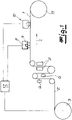
- the coating unit 6 or the two coating units 6 for the material web 2 follows in the 1 a crosslinking unit 7 in the processing direction indicated by an arrow or in the longitudinal direction L of the material web 2.
- the crosslinking unit 7 has UV lamps or UV LEDs, with the help of which the adhesive strips 4 applied to the respective surface of the material web 2 can be applied if necessary be networked. This means that the crosslinking unit 7 is to be considered as an option in the present case.
- the crosslinking unit 7 is designed in two parts, assigned to the respective surface of the material web 2 . This can be attributed to the fact that, according to the exemplary embodiment, both surfaces of the web of material 2 are equipped with associated adhesive strips 4 .
- the processing direction or longitudinal direction L of the material web 2 can be seen in the overview drawing according to FIG 1 first a sensor 8, 9, the function and characteristics of which will be explained in more detail below.
- the sensor 8, 9 is followed by a cutting device 10, with the help of which in each case 2 to be recognized cuts in the longitudinal direction or longitudinal cuts S are introduced into the material web 2.
- the cutting device 10 has a cutter bar, which is suitable and provided for the storage of knives rotating about a transverse axis, as is the case in the prior art according to FIG EP 2 744 865 B1 shows and describes as an example.
- the individual adhesive tapes 1 are made up and can, for example, be received or wound up on a winding unit 11 .
- the material web 2 is one in which a polyester fabric web is supplied as the carrier strip material.
- the web of material 2 can also be a fleece web, a film web, a paper web, and combinations thereof.
- the material web 2 is scanned with the aid of the sensor 8 , 9 .
- the sensor 8 , 9 is provided and placed above a surface of the material web 2 .
- the surface of the material web 2 pointing upwards is scanned with the local adhesive strip 4, which of course only applies as an example.
- the sensor 8, 9 as a whole can emit signals to a control unit 12, which, according to the supervision, is shown in FIG 3 to a topological edge course A; K 1 , K 2 of the respective adhesive strip 4 correspond.
- K 1 , K 2 of the adhesive strip 4 is in the context of the representation after 3 and the exemplary embodiment, a distance A between two edges K 1 , K 2 and the associated values for the distance A in the longitudinal direction L of the material web 2.
- edge K 1 is according to the embodiment in the 3 meaning the left edge of the material web 2 in the feed direction or longitudinal direction L.
- the edge K 2 designates the right-hand edge in the running direction or longitudinal direction L of the adhesive strip 4 that is closest to the edge K 1 of the material web 2.
- the topological course of the edges A; K 1 , K 2 now reflect the values for the respective distance A between the two edges K 1 and K 2 , depending on the respective position of the material web 2 in the longitudinal direction L.
- the individual values for the distance A, which are dependent on the longitudinal direction L, are fed into the control unit 12 as signals from the sensor 8, 9.
- the course of the K 2 can be detected.
- the course of the edge K 1 of the material web 2 is determined and sent to the control unit 12 . From the two values for the position of the respective edge K 1 , K 2 depending on its position in comparison to the longitudinal direction L of the material web 2, the control unit 12 can determine the already described topological course of the edges A; Determine K 1 , K 2 .
- the senor 8, 9 is first of all equipped in such a way that it can scan the material web 2 for differences in contrast.
- the contrast differences are different values for the light reflection from the adhesive-free surface of the material web 2 on the one hand and the adhesive strips 4 on the other.
- the illumination source 9 is the camera 8, for example LEDs surrounding it in a ring shape, which in the present case emit long-wave light in the visible spectrum, for example red light.
- This red light from the illumination source 9 is reflected differently by the material web 2 .
- the material web 2 is largely opaque on its adhesive-free surface next to the adhesive strip 4, ie it has only low light reflection.
- the adhesive strip 4 ensures increased light reflection in the visible range, which can typically be attributed to its “silver character” when viewed from above.
- the sensor 8, 9 can use these contrast differences to draw conclusions about the course of the edge K 2 on the right in the feed direction or longitudinal direction L of the adhesive strip 4 examined.
- the overall distance A between the two edges K 1 , K 2 can be determined as a function of the position of the material web 2 transmit to the control unit 12 and evaluate here.
- the material web 2 has the same overall width throughout, so that fluctuations in the previously explained distance A are solely due to movements of the material web 2 in the 3 indicated transverse direction Q are due.
- the respective coating unit applying the adhesive strips 4 to the material web 2 is provided 6 designed so that the individual and in the 3 adhesive strips 4 shown in plan have a constant distance from each other. This is because at this point one or more respective nozzles are used for dispensing the adhesive, which are arranged and placed mechanically fixed to one another and at a fixed distance from one another in the respective coating unit 6 .
- the distance A between the left edge K 1 of the material web 2 in the running direction or longitudinal direction L in comparison to the right edge K 2 of the adhesive strip 4 adjacent to the edge K 1 can serve as a total measure and be used to determine how large any Displacement ⁇ q of the material web 2 in the transverse direction Q when passing through the device after 1 is measured.
- control unit 12 is embodied as a regulating unit 12 in the present case.
- the distance A in question or, overall, the topological course of the edge A functions; K 1 , K 2 as controlled variable.
- a target value for the distance A in question can be specified in the control unit or regulating unit 12 .
- the control unit 12 ensures that the material web 2 is tracked or aligned in the transverse direction.
- the sensor 8, 9 measures a distance A that is smaller by the amount ⁇ q than specified by the target value A, this corresponds to a corresponding movement of the unwinding unit 3 with the aid of the drive 14 in the opposite direction, i.e. in the present case in the feed direction or longitudinal direction L to the left in the transverse direction Q. This is also indicated by an arrow.
- the material web 2 in the exemplary embodiment is aligned in the transverse direction Q before or even during the cutting process using the cutting device 10 and after the material web 2 has been provided with the respective adhesive strip 4 using the sensor 8, 9 scanning the material web 2.
- the alignment in the transverse direction Q of the web of material 2 takes place in such a way that a longitudinal cut or the plurality of longitudinal cuts S produced with the aid of the cutting device 10 are introduced into the web of material 2 with precise positioning, as is shown in FIG 2 is shown.
- the web of material 2 is examined for contrast differences between the adhesive-free surface and the respective adhesive strip 4 for this purpose.
- the contrast differences shown which are evaluated using the sensor 8, 9, correspond to different light reflections from the adhesive-free surface on the one hand and the adhesive strip 4 on the other.
- the sensor 8, 9 determines the topological edge profile A from these contrast differences; K 1 , K 2 of the relevant adhesive strip 4 on the material web 2.
- the material web 2 moved in the transverse direction Q namely the unwinding unit 3 .
- the unwinding unit 3 is assigned the drive 14 which ensures a travel movement in the transverse direction Q of the material web 2 .
- each generated and in the 2 illustrated longitudinal section S at the edge of the associated adhesive strip 4 optionally taking into account a predetermined minimum distance T to the relevant edge K 2 of the adhesive strip 4 in the web of material 2.
- This minimum distance T ensures that when the rotating knives of the cutting device 10 are immersed, the knives in question do not come into contact with the respective adhesive strip 4 .
- the signals transmitted by the sensor 8, 9 to the control unit 12 are used to evaluate both the course of the edge K1 of the material web 2 as a whole and the edge K2 of the at least one adhesive strip 4 examined.
- all adhesive strips 4 on the 3 to detect the surface of the web of material shown using the sensor 8 , 9 .
- the respective edge profile K 2 of the associated adhesive strip 4 can be averaged in the control unit 12 .
- the adhesive strips 4 are applied to the surface of the material web 2 at a fixed distance from one another with the aid of the respective coating unit 6, such a measurement of a plurality of adhesive strips 4 is strictly speaking not necessary, although it is possible. - In principle, the device and the method can work continuously. However, discontinuous operation is also possible, although this is not shown.
Claims (9)
- Procédé de fabrication d'une bande adhésive (1) avec les étapes de procédé suivantes :1.1) une nappe de matière (2) d'un matériau de bande porteuse est acheminée par une unité de déroulement (3),1.2) la nappe de matière (2) acheminée est ensuite dotée d'au moins une bande d'adhésif (4) sur au moins une surface dans une unité de revêtement (6),1.3) la nappe de matière (2) dotée de la bande d'adhésif (4) est ensuite découpée à l'aide d'un dispositif de découpe (10) en au moins deux bandes longitudinales et confectionnée en bandes adhésives individuelles (1),caractérisé en ce que1.4) la nappe de matière (2) est orientée dans la direction transversale (Q) avant ou lors de l'opération de découpe selon 1.3) et après la dotation avec la bande d'adhésif (4) selon 1.2) à l'aide d'un capteur (8, 9) analysant la nappe de matière (2) de telle manière qu'une coupe longitudinale (S) produite respectivement à l'aide du dispositif de découpe (10) est apportée en position exacte dans la nappe de matière (2) et qu'à cet effet1.5) un entraînement (14) raccordé à une unité de commande (12) pour l'unité de déroulement (3) est déplacé dans la direction transversale (Q) par comparaison à la direction d'avance ou la direction longitudinale (L).
- Procédé selon la revendication 1, caractérisé en ce que le capteur (8, 9) analyse la nappe de matière (2) eu égard aux différences de contraste.
- Procédé selon la revendication 2, caractérisé en ce que concernant les différences de contraste, il s'agit de réflexions lumineuses différentes d'une part de la surface sans adhésif de la nappe de matière (2) et d'autre part de la bande d'adhésif (4).
- Procédé selon l'une quelconque des revendications 1 à 3, caractérisé en ce que le capteur (8, 9) saisit en liaison avec une unité de commande (12) évaluant ses valeurs de signaux, un profil de bord topologique (A, K1, K2) de la bande d'adhésif (4) sur la nappe de matière (2) à partir des différences de contraste entre la surface dépourvue d'adhésif de la nappe de matière (2) et la bande d'adhésif (4).
- Procédé selon l'une quelconque des revendications 1 à 4, caractérisé en ce que la coupe longitudinale (S) respectivement produite sur le bord de la bande d'adhésif (4) est apportée le cas échéant dans la nappe de matière (2) en tenant compte d'une distance minimale prédéfinie (T) par rapport au bord (K2) de la bande d'adhésif (4).
- Procédé selon l'une quelconque des revendications 1 à 5, caractérisé en ce que les signaux transmis par le capteur (8, 9) à l'unité de commande (12) pour le profil de bord (A, K1, K2) de la bande d'adhésif (4) font fonction de valeur de réglage pour un mouvement de réglage de la nappe de matière (2) dans la direction transversale (Q).
- Dispositif de fabrication d'une bande adhésive (1), en particulier pour exécuter le procédé selon l'une quelconque des revendications 1 à 6, avec une unité de déroulement (3), laquelle achemine une nappe de matière (2) d'un matériau de bande porteuse, en plus avec une unité de revêtement (6) pour doter la nappe de matière (2) sur au moins une surface d'au moins une bande d'adhésif (4), et avec un dispositif de découpe (10), lequel découpe la nappe de matière (2) dotée de la bande d'adhésif (4) en au moins deux bandes longitudinales, lesquelles sont confectionnées finalement dans la bande adhésive en question (1),
caractérisé en ce qu'
un capteur (8, 9) est prévu, lequel analyse la nappe de matière (2) et dont les signaux sont évalués par une unité de commande (12) pour l'orientation de la nappe de matière (2) en direction transversale (Q) pour apporter les coupes longitudinales (S) respectivement apportées à l'aide du dispositif de découpe (10) dans la nappe de matière (2) exactement en position dans la nappe de matière (2) et un entraînement (14) pour l'unité de déroulement (3), raccordé à l'unité de commande (12) est déplacé à cet effet dans la direction transversale (Q) en comparaison à la direction d'avance ou la direction longitudinale (L). - Dispositif selon la revendication 7, caractérisé en ce que le capteur (8, 9) est constitué comme capteur optique (8, 9) analysant les différences de contraste de la nappe de matière (2) dans un spectre visible.
- Dispositif selon la revendication 8, caractérisé en ce que le capteur optique (8, 9) comporte une caméra (8).
Applications Claiming Priority (2)
| Application Number | Priority Date | Filing Date | Title |
|---|---|---|---|
| DE102017120419.9A DE102017120419A1 (de) | 2017-09-05 | 2017-09-05 | Verfahren und Einrichtung zur Herstellung eines Klebebandes |
| PCT/EP2018/072646 WO2019048232A1 (fr) | 2017-09-05 | 2018-08-22 | Procédé et dispositif pour la fabrication d'un ruban adhésif |
Publications (2)
| Publication Number | Publication Date |
|---|---|
| EP3679102A1 EP3679102A1 (fr) | 2020-07-15 |
| EP3679102B1 true EP3679102B1 (fr) | 2022-04-27 |
Family
ID=63364061
Family Applications (1)
| Application Number | Title | Priority Date | Filing Date |
|---|---|---|---|
| EP18759289.4A Active EP3679102B1 (fr) | 2017-09-05 | 2018-08-22 | Procédé et dispositif pour la fabrication d'un ruban adhésif |
Country Status (5)
| Country | Link |
|---|---|
| US (1) | US11498791B2 (fr) |
| EP (1) | EP3679102B1 (fr) |
| CN (1) | CN111065702B (fr) |
| DE (1) | DE102017120419A1 (fr) |
| WO (1) | WO2019048232A1 (fr) |
Families Citing this family (2)
| Publication number | Priority date | Publication date | Assignee | Title |
|---|---|---|---|---|
| DE102017120419A1 (de) * | 2017-09-05 | 2019-03-07 | Certoplast Technische Klebebänder Gmbh | Verfahren und Einrichtung zur Herstellung eines Klebebandes |
| CN112357653B (zh) * | 2021-01-12 | 2021-04-23 | 潍坊科技学院 | 具有防腐涂料喷涂机构的金属薄板卷绕输送装置 |
Family Cites Families (25)
| Publication number | Priority date | Publication date | Assignee | Title |
|---|---|---|---|---|
| US4460634A (en) * | 1979-12-29 | 1984-07-17 | Masaaki Hasegawa | Adhesive sheet and method for manufacturing the same |
| GB2152005B (en) * | 1983-12-23 | 1987-07-15 | Photoleaflets | Self-adhesive prints or labels |
| JPH0679695A (ja) * | 1992-08-28 | 1994-03-22 | New Oji Paper Co Ltd | 粘着紙の断裁方法 |
| US5725320A (en) * | 1995-05-04 | 1998-03-10 | Intermec Corporation | Linerless media and cutting apparatus for minimizing adhesive problems when cutting the media |
| US5730354A (en) * | 1996-07-12 | 1998-03-24 | Kt Industries Inc. | Printed tear tape |
| US6268032B1 (en) * | 1997-10-03 | 2001-07-31 | 3M Innovative Properties Company | Repositionable note sheets and method of formation thereof |
| CN1127546C (zh) * | 1998-02-02 | 2003-11-12 | 株式会社辻电 | 双面胶带的制造方法与制造装置 |
| US6394330B1 (en) * | 1998-08-13 | 2002-05-28 | 3M Innovative Properties Company | Method for slitting and processing a web into plural use supply forms |
| DE10001816C1 (de) * | 1999-11-13 | 2001-06-21 | Erhardt & Leimer Gmbh | Vorrichtung und Verfahren zum Führen einer querstabilen Warenbahn |
| DE10042732A1 (de) | 2000-08-31 | 2002-03-28 | Tesa Ag | Verfahren zur Ummantelung von langgestrecktem Gut, wie insbesondere Kabelsätzen mit einem Klebeband |
| GB0106816D0 (en) * | 2001-03-19 | 2001-05-09 | Rue De Int Ltd | Sheet handling apparatus and method |
| JP2005177617A (ja) * | 2003-12-19 | 2005-07-07 | Toshiba Corp | 紙葉類裁断装置 |
| EP2007936B1 (fr) * | 2006-04-05 | 2013-06-12 | i-cut, inc. | Procédé et appareil de coupe d'étoffe sans éraillure |
| US7615128B2 (en) * | 2006-04-05 | 2009-11-10 | Mikkelsen Graphic Engineering, Inc. | Method and apparatus for fray-free textile cutting |
| WO2009118826A1 (fr) * | 2008-03-25 | 2009-10-01 | 株式会社イトウ六 | Procédé de production d'un long rouleau de ruban adhésif de largeur extrafine et appareil dans ce but |
| CN101559889B (zh) * | 2008-04-16 | 2011-06-01 | 日东电工株式会社 | 辊状卷料组及辊状卷料的制造方法 |
| DE202010014239U1 (de) | 2010-10-14 | 2010-12-30 | Certoplast Vorwerk & Sohn Gmbh | Klebeband sowie aus dem Klebeband hergestellte Schlauchummantelung |
| WO2012167806A1 (fr) | 2011-06-10 | 2012-12-13 | Bixolon Europe Gmbh | Imprimante destinée à imprimer une bande revêtue de colle sur une face |
| DE102011052821A1 (de) * | 2011-08-18 | 2013-02-21 | Certoplast Vorwerk & Sohn Gmbh | Verfahren und Vorrichtung zur Herstellung eines Klebebandes |
| JP2014086478A (ja) * | 2012-10-22 | 2014-05-12 | Nitto Denko Corp | イメージセンサの製造方法およびそれに用いる積層型耐熱性保護テープ |
| GB2523390B (en) | 2014-02-24 | 2017-11-29 | Essentra Packaging & Security Ltd | Method and apparatus for manufacturing a tape |
| GB2523389A (en) * | 2014-02-24 | 2015-08-26 | Essentra Packaging & Security Ltd | Method and apparatus for manufacturing a tape |
| DE202015103713U1 (de) * | 2015-07-15 | 2015-07-27 | Certoplast Technische Klebebänder Gmbh | Klebeband |
| CN206123749U (zh) * | 2016-08-30 | 2017-04-26 | 浙江绿洲胶粘制品有限公司 | 一种胶带分切机 |
| DE102017120419A1 (de) * | 2017-09-05 | 2019-03-07 | Certoplast Technische Klebebänder Gmbh | Verfahren und Einrichtung zur Herstellung eines Klebebandes |
-
2017
- 2017-09-05 DE DE102017120419.9A patent/DE102017120419A1/de not_active Withdrawn
-
2018
- 2018-08-22 CN CN201880057502.4A patent/CN111065702B/zh active Active
- 2018-08-22 US US16/639,276 patent/US11498791B2/en active Active
- 2018-08-22 WO PCT/EP2018/072646 patent/WO2019048232A1/fr unknown
- 2018-08-22 EP EP18759289.4A patent/EP3679102B1/fr active Active
Also Published As
| Publication number | Publication date |
|---|---|
| DE102017120419A1 (de) | 2019-03-07 |
| CN111065702B (zh) | 2022-06-03 |
| CN111065702A (zh) | 2020-04-24 |
| WO2019048232A8 (fr) | 2019-05-16 |
| US11498791B2 (en) | 2022-11-15 |
| US20200247635A1 (en) | 2020-08-06 |
| WO2019048232A1 (fr) | 2019-03-14 |
| EP3679102A1 (fr) | 2020-07-15 |
Similar Documents
| Publication | Publication Date | Title |
|---|---|---|
| DE2424041A1 (de) | Zusammengesetztes band endlicher laenge, insbesondere zum uebertragen von signalen in fernuebertragungskabeln | |
| DE3218304A1 (de) | Vorrichtung zum abtrennen von endlosformularsaetzen o.dgl. | |
| EP3679102B1 (fr) | Procédé et dispositif pour la fabrication d'un ruban adhésif | |
| DE2530992B2 (de) | Vorrichtung zum Herstellen von Verpackungszuschnitten | |
| EP0360108A1 (fr) | Procédé et dispositif pour la distribution d'étiquettes | |
| EP2401220A1 (fr) | Procédé et dispositif pour le collage d'un bord d'un objet plat | |
| DE102017105154B4 (de) | Vorrichtung und Verfahren zum Zertrennen eines Bands in eine Vielzahl von einzelnen Bandstücken | |
| WO2020225369A1 (fr) | Machine de formage et procédé de production de pièces cintrées à partir d'un matériau allongé isolé doté d'extrémités dénudées | |
| DE3203162A1 (de) | Verfahren und vorrichtung zum etikettieren von gegenstaenden | |
| EP0220415A2 (fr) | Machine pour couper des plaques | |
| DE19519584A1 (de) | Verfahren und Vorrichtung zum Herstellen von vorgeschnittenen, noch weiter bearbeitbaren Einzelabschnitten sowie Bögen mit vorgeschnittenen Einzelabschnitten | |
| EP0381112B1 (fr) | Procédé et dispositif pour travailler des bandes en registre, spécialement pour des fils de sécurités | |
| EP3403557A1 (fr) | Dispositif de sortie de sections de papier de longueur prédéfinie | |
| CH690323A5 (de) | Verfahren und Vorrichtung zum Schneiden von kontinuierlich geforderten, flochigen Produkten insbesondere aus Papier. | |
| DE2421376A1 (de) | Verfahren zur herstellung von elektrischen spulen | |
| EP0401289A1 (fr) | Porte-etiquette a bandes et son dispositif de fabrication | |
| EP0931631A2 (fr) | Dispositif pour rogner les bords d'un matériau en bande | |
| DE2409608C2 (de) | Vorrichtung zum Behandeln eines Materialbandes aus zusammendrückbarem Fasergut und zugehörigem Verfahren | |
| EP2919993B1 (fr) | Système de surveillance pour l'orientation de groupes d'impression d'une machine à imprimer en ligne | |
| DE102008061165A1 (de) | Verfahren und Vorrichtung zum Herstellen von Halbleiterbauelementen mit einer Folie | |
| WO1992021568A1 (fr) | Procede et dispositif d'application sur un substrat d'une pellicule adhesive eventuellement enduite | |
| EP1542859B1 (fr) | Procede de mise a disposition de feuilles en continu | |
| EP0536685A1 (fr) | Dispositif pour perforer, en relation avec la qualité du matériel, des bandes de formulaires | |
| WO2023220763A1 (fr) | Ruban de fibres optiques et son procede de production | |
| DE1113728B (de) | Verfahren und Fertigungseinrichtung zur kontinuierlichen Erstellung von geklebten oder umspritzten Bandkabeln mit ausgeformten Loetoesen |
Legal Events
| Date | Code | Title | Description |
|---|---|---|---|
| STAA | Information on the status of an ep patent application or granted ep patent |
Free format text: STATUS: UNKNOWN |
|
| STAA | Information on the status of an ep patent application or granted ep patent |
Free format text: STATUS: THE INTERNATIONAL PUBLICATION HAS BEEN MADE |
|
| PUAI | Public reference made under article 153(3) epc to a published international application that has entered the european phase |
Free format text: ORIGINAL CODE: 0009012 |
|
| STAA | Information on the status of an ep patent application or granted ep patent |
Free format text: STATUS: REQUEST FOR EXAMINATION WAS MADE |
|
| 17P | Request for examination filed |
Effective date: 20200218 |
|
| AK | Designated contracting states |
Kind code of ref document: A1 Designated state(s): AL AT BE BG CH CY CZ DE DK EE ES FI FR GB GR HR HU IE IS IT LI LT LU LV MC MK MT NL NO PL PT RO RS SE SI SK SM TR |
|
| AX | Request for extension of the european patent |
Extension state: BA ME |
|
| DAV | Request for validation of the european patent (deleted) | ||
| DAX | Request for extension of the european patent (deleted) | ||
| GRAP | Despatch of communication of intention to grant a patent |
Free format text: ORIGINAL CODE: EPIDOSNIGR1 |
|
| STAA | Information on the status of an ep patent application or granted ep patent |
Free format text: STATUS: GRANT OF PATENT IS INTENDED |
|
| RIC1 | Information provided on ipc code assigned before grant |
Ipc: B65H 23/032 20060101ALI20211124BHEP Ipc: B65H 18/10 20060101ALI20211124BHEP Ipc: B26D 7/26 20060101ALI20211124BHEP Ipc: C09J 7/30 20180101AFI20211124BHEP |
|
| INTG | Intention to grant announced |
Effective date: 20211222 |
|
| GRAS | Grant fee paid |
Free format text: ORIGINAL CODE: EPIDOSNIGR3 |
|
| GRAA | (expected) grant |
Free format text: ORIGINAL CODE: 0009210 |
|
| STAA | Information on the status of an ep patent application or granted ep patent |
Free format text: STATUS: THE PATENT HAS BEEN GRANTED |
|
| AK | Designated contracting states |
Kind code of ref document: B1 Designated state(s): AL AT BE BG CH CY CZ DE DK EE ES FI FR GB GR HR HU IE IS IT LI LT LU LV MC MK MT NL NO PL PT RO RS SE SI SK SM TR |
|
| REG | Reference to a national code |
Ref country code: GB Ref legal event code: FG4D Free format text: NOT ENGLISH |
|
| REG | Reference to a national code |
Ref country code: CH Ref legal event code: EP |
|
| REG | Reference to a national code |
Ref country code: AT Ref legal event code: REF Ref document number: 1486941 Country of ref document: AT Kind code of ref document: T Effective date: 20220515 |
|
| REG | Reference to a national code |
Ref country code: DE Ref legal event code: R096 Ref document number: 502018009516 Country of ref document: DE |
|
| REG | Reference to a national code |
Ref country code: IE Ref legal event code: FG4D Free format text: LANGUAGE OF EP DOCUMENT: GERMAN |
|
| REG | Reference to a national code |
Ref country code: LT Ref legal event code: MG9D |
|
| REG | Reference to a national code |
Ref country code: NL Ref legal event code: MP Effective date: 20220427 |
|
| PG25 | Lapsed in a contracting state [announced via postgrant information from national office to epo] |
Ref country code: NL Free format text: LAPSE BECAUSE OF FAILURE TO SUBMIT A TRANSLATION OF THE DESCRIPTION OR TO PAY THE FEE WITHIN THE PRESCRIBED TIME-LIMIT Effective date: 20220427 |
|
| PG25 | Lapsed in a contracting state [announced via postgrant information from national office to epo] |
Ref country code: SE Free format text: LAPSE BECAUSE OF FAILURE TO SUBMIT A TRANSLATION OF THE DESCRIPTION OR TO PAY THE FEE WITHIN THE PRESCRIBED TIME-LIMIT Effective date: 20220427 Ref country code: PT Free format text: LAPSE BECAUSE OF FAILURE TO SUBMIT A TRANSLATION OF THE DESCRIPTION OR TO PAY THE FEE WITHIN THE PRESCRIBED TIME-LIMIT Effective date: 20220829 Ref country code: NO Free format text: LAPSE BECAUSE OF FAILURE TO SUBMIT A TRANSLATION OF THE DESCRIPTION OR TO PAY THE FEE WITHIN THE PRESCRIBED TIME-LIMIT Effective date: 20220727 Ref country code: LT Free format text: LAPSE BECAUSE OF FAILURE TO SUBMIT A TRANSLATION OF THE DESCRIPTION OR TO PAY THE FEE WITHIN THE PRESCRIBED TIME-LIMIT Effective date: 20220427 Ref country code: HR Free format text: LAPSE BECAUSE OF FAILURE TO SUBMIT A TRANSLATION OF THE DESCRIPTION OR TO PAY THE FEE WITHIN THE PRESCRIBED TIME-LIMIT Effective date: 20220427 Ref country code: GR Free format text: LAPSE BECAUSE OF FAILURE TO SUBMIT A TRANSLATION OF THE DESCRIPTION OR TO PAY THE FEE WITHIN THE PRESCRIBED TIME-LIMIT Effective date: 20220728 Ref country code: FI Free format text: LAPSE BECAUSE OF FAILURE TO SUBMIT A TRANSLATION OF THE DESCRIPTION OR TO PAY THE FEE WITHIN THE PRESCRIBED TIME-LIMIT Effective date: 20220427 Ref country code: ES Free format text: LAPSE BECAUSE OF FAILURE TO SUBMIT A TRANSLATION OF THE DESCRIPTION OR TO PAY THE FEE WITHIN THE PRESCRIBED TIME-LIMIT Effective date: 20220427 Ref country code: BG Free format text: LAPSE BECAUSE OF FAILURE TO SUBMIT A TRANSLATION OF THE DESCRIPTION OR TO PAY THE FEE WITHIN THE PRESCRIBED TIME-LIMIT Effective date: 20220727 |
|
| PG25 | Lapsed in a contracting state [announced via postgrant information from national office to epo] |
Ref country code: RS Free format text: LAPSE BECAUSE OF FAILURE TO SUBMIT A TRANSLATION OF THE DESCRIPTION OR TO PAY THE FEE WITHIN THE PRESCRIBED TIME-LIMIT Effective date: 20220427 Ref country code: PL Free format text: LAPSE BECAUSE OF FAILURE TO SUBMIT A TRANSLATION OF THE DESCRIPTION OR TO PAY THE FEE WITHIN THE PRESCRIBED TIME-LIMIT Effective date: 20220427 Ref country code: LV Free format text: LAPSE BECAUSE OF FAILURE TO SUBMIT A TRANSLATION OF THE DESCRIPTION OR TO PAY THE FEE WITHIN THE PRESCRIBED TIME-LIMIT Effective date: 20220427 Ref country code: IS Free format text: LAPSE BECAUSE OF FAILURE TO SUBMIT A TRANSLATION OF THE DESCRIPTION OR TO PAY THE FEE WITHIN THE PRESCRIBED TIME-LIMIT Effective date: 20220827 |
|
| REG | Reference to a national code |
Ref country code: DE Ref legal event code: R097 Ref document number: 502018009516 Country of ref document: DE |
|
| PG25 | Lapsed in a contracting state [announced via postgrant information from national office to epo] |
Ref country code: SM Free format text: LAPSE BECAUSE OF FAILURE TO SUBMIT A TRANSLATION OF THE DESCRIPTION OR TO PAY THE FEE WITHIN THE PRESCRIBED TIME-LIMIT Effective date: 20220427 Ref country code: SK Free format text: LAPSE BECAUSE OF FAILURE TO SUBMIT A TRANSLATION OF THE DESCRIPTION OR TO PAY THE FEE WITHIN THE PRESCRIBED TIME-LIMIT Effective date: 20220427 Ref country code: RO Free format text: LAPSE BECAUSE OF FAILURE TO SUBMIT A TRANSLATION OF THE DESCRIPTION OR TO PAY THE FEE WITHIN THE PRESCRIBED TIME-LIMIT Effective date: 20220427 Ref country code: EE Free format text: LAPSE BECAUSE OF FAILURE TO SUBMIT A TRANSLATION OF THE DESCRIPTION OR TO PAY THE FEE WITHIN THE PRESCRIBED TIME-LIMIT Effective date: 20220427 Ref country code: DK Free format text: LAPSE BECAUSE OF FAILURE TO SUBMIT A TRANSLATION OF THE DESCRIPTION OR TO PAY THE FEE WITHIN THE PRESCRIBED TIME-LIMIT Effective date: 20220427 Ref country code: CZ Free format text: LAPSE BECAUSE OF FAILURE TO SUBMIT A TRANSLATION OF THE DESCRIPTION OR TO PAY THE FEE WITHIN THE PRESCRIBED TIME-LIMIT Effective date: 20220427 |
|
| PLBE | No opposition filed within time limit |
Free format text: ORIGINAL CODE: 0009261 |
|
| STAA | Information on the status of an ep patent application or granted ep patent |
Free format text: STATUS: NO OPPOSITION FILED WITHIN TIME LIMIT |
|
| PG25 | Lapsed in a contracting state [announced via postgrant information from national office to epo] |
Ref country code: MC Free format text: LAPSE BECAUSE OF FAILURE TO SUBMIT A TRANSLATION OF THE DESCRIPTION OR TO PAY THE FEE WITHIN THE PRESCRIBED TIME-LIMIT Effective date: 20220427 Ref country code: AL Free format text: LAPSE BECAUSE OF FAILURE TO SUBMIT A TRANSLATION OF THE DESCRIPTION OR TO PAY THE FEE WITHIN THE PRESCRIBED TIME-LIMIT Effective date: 20220427 |
|
| REG | Reference to a national code |
Ref country code: CH Ref legal event code: PL |
|
| 26N | No opposition filed |
Effective date: 20230130 |
|
| PG25 | Lapsed in a contracting state [announced via postgrant information from national office to epo] |
Ref country code: LU Free format text: LAPSE BECAUSE OF NON-PAYMENT OF DUE FEES Effective date: 20220822 Ref country code: LI Free format text: LAPSE BECAUSE OF NON-PAYMENT OF DUE FEES Effective date: 20220831 Ref country code: CH Free format text: LAPSE BECAUSE OF NON-PAYMENT OF DUE FEES Effective date: 20220831 |
|
| REG | Reference to a national code |
Ref country code: BE Ref legal event code: MM Effective date: 20220831 |
|
| PG25 | Lapsed in a contracting state [announced via postgrant information from national office to epo] |
Ref country code: SI Free format text: LAPSE BECAUSE OF FAILURE TO SUBMIT A TRANSLATION OF THE DESCRIPTION OR TO PAY THE FEE WITHIN THE PRESCRIBED TIME-LIMIT Effective date: 20220427 |
|
| PG25 | Lapsed in a contracting state [announced via postgrant information from national office to epo] |
Ref country code: IE Free format text: LAPSE BECAUSE OF NON-PAYMENT OF DUE FEES Effective date: 20220822 |
|
| PG25 | Lapsed in a contracting state [announced via postgrant information from national office to epo] |
Ref country code: BE Free format text: LAPSE BECAUSE OF NON-PAYMENT OF DUE FEES Effective date: 20220831 |
|
| PGFP | Annual fee paid to national office [announced via postgrant information from national office to epo] |
Ref country code: IT Payment date: 20230825 Year of fee payment: 6 Ref country code: GB Payment date: 20230822 Year of fee payment: 6 |
|
| PGFP | Annual fee paid to national office [announced via postgrant information from national office to epo] |
Ref country code: FR Payment date: 20230828 Year of fee payment: 6 Ref country code: DE Payment date: 20230707 Year of fee payment: 6 |
|
| PG25 | Lapsed in a contracting state [announced via postgrant information from national office to epo] |
Ref country code: CY Free format text: LAPSE BECAUSE OF FAILURE TO SUBMIT A TRANSLATION OF THE DESCRIPTION OR TO PAY THE FEE WITHIN THE PRESCRIBED TIME-LIMIT Effective date: 20220427 |