EP3679102B1 - Method and device for producing an adhesive tape - Google Patents
Method and device for producing an adhesive tape Download PDFInfo
- Publication number
- EP3679102B1 EP3679102B1 EP18759289.4A EP18759289A EP3679102B1 EP 3679102 B1 EP3679102 B1 EP 3679102B1 EP 18759289 A EP18759289 A EP 18759289A EP 3679102 B1 EP3679102 B1 EP 3679102B1
- Authority
- EP
- European Patent Office
- Prior art keywords
- material web
- adhesive
- adhesive strip
- sensor
- web
- Prior art date
- Legal status (The legal status is an assumption and is not a legal conclusion. Google has not performed a legal analysis and makes no representation as to the accuracy of the status listed.)
- Active
Links
- 239000002390 adhesive tape Substances 0.000 title claims description 40
- 238000000034 method Methods 0.000 title claims description 21
- 239000000463 material Substances 0.000 claims description 119
- 239000000853 adhesive Substances 0.000 claims description 86
- 230000001070 adhesive effect Effects 0.000 claims description 86
- 238000005520 cutting process Methods 0.000 claims description 22
- 239000011248 coating agent Substances 0.000 claims description 17
- 238000000576 coating method Methods 0.000 claims description 17
- 238000004519 manufacturing process Methods 0.000 claims description 4
- 238000001429 visible spectrum Methods 0.000 claims description 2
- 230000003287 optical effect Effects 0.000 claims 2
- 238000004804 winding Methods 0.000 description 10
- 239000004744 fabric Substances 0.000 description 7
- 238000004132 cross linking Methods 0.000 description 4
- 229920000728 polyester Polymers 0.000 description 4
- 238000005286 illumination Methods 0.000 description 2
- 230000001105 regulatory effect Effects 0.000 description 2
- 230000001419 dependent effect Effects 0.000 description 1
- 238000006073 displacement reaction Methods 0.000 description 1
- 230000000694 effects Effects 0.000 description 1
- 239000003292 glue Substances 0.000 description 1
- 239000007788 liquid Substances 0.000 description 1
- 238000005259 measurement Methods 0.000 description 1
- 229910052709 silver Inorganic materials 0.000 description 1
- 239000004332 silver Substances 0.000 description 1
- 230000003595 spectral effect Effects 0.000 description 1
- 238000001228 spectrum Methods 0.000 description 1
- 238000003860 storage Methods 0.000 description 1
Images


Classifications
-
- C—CHEMISTRY; METALLURGY
- C09—DYES; PAINTS; POLISHES; NATURAL RESINS; ADHESIVES; COMPOSITIONS NOT OTHERWISE PROVIDED FOR; APPLICATIONS OF MATERIALS NOT OTHERWISE PROVIDED FOR
- C09J—ADHESIVES; NON-MECHANICAL ASPECTS OF ADHESIVE PROCESSES IN GENERAL; ADHESIVE PROCESSES NOT PROVIDED FOR ELSEWHERE; USE OF MATERIALS AS ADHESIVES
- C09J7/00—Adhesives in the form of films or foils
- C09J7/30—Adhesives in the form of films or foils characterised by the adhesive composition
-
- B—PERFORMING OPERATIONS; TRANSPORTING
- B65—CONVEYING; PACKING; STORING; HANDLING THIN OR FILAMENTARY MATERIAL
- B65H—HANDLING THIN OR FILAMENTARY MATERIAL, e.g. SHEETS, WEBS, CABLES
- B65H18/00—Winding webs
- B65H18/08—Web-winding mechanisms
- B65H18/10—Mechanisms in which power is applied to web-roll spindle
- B65H18/103—Reel-to-reel type web winding and unwinding mechanisms
-
- B—PERFORMING OPERATIONS; TRANSPORTING
- B26—HAND CUTTING TOOLS; CUTTING; SEVERING
- B26D—CUTTING; DETAILS COMMON TO MACHINES FOR PERFORATING, PUNCHING, CUTTING-OUT, STAMPING-OUT OR SEVERING
- B26D1/00—Cutting through work characterised by the nature or movement of the cutting member or particular materials not otherwise provided for; Apparatus or machines therefor; Cutting members therefor
- B26D1/01—Cutting through work characterised by the nature or movement of the cutting member or particular materials not otherwise provided for; Apparatus or machines therefor; Cutting members therefor involving a cutting member which does not travel with the work
- B26D1/12—Cutting through work characterised by the nature or movement of the cutting member or particular materials not otherwise provided for; Apparatus or machines therefor; Cutting members therefor involving a cutting member which does not travel with the work having a cutting member moving about an axis
- B26D1/14—Cutting through work characterised by the nature or movement of the cutting member or particular materials not otherwise provided for; Apparatus or machines therefor; Cutting members therefor involving a cutting member which does not travel with the work having a cutting member moving about an axis with a circular cutting member, e.g. disc cutter
- B26D1/157—Cutting through work characterised by the nature or movement of the cutting member or particular materials not otherwise provided for; Apparatus or machines therefor; Cutting members therefor involving a cutting member which does not travel with the work having a cutting member moving about an axis with a circular cutting member, e.g. disc cutter rotating about a movable axis
- B26D1/18—Cutting through work characterised by the nature or movement of the cutting member or particular materials not otherwise provided for; Apparatus or machines therefor; Cutting members therefor involving a cutting member which does not travel with the work having a cutting member moving about an axis with a circular cutting member, e.g. disc cutter rotating about a movable axis mounted on a movable carriage
- B26D1/185—Cutting through work characterised by the nature or movement of the cutting member or particular materials not otherwise provided for; Apparatus or machines therefor; Cutting members therefor involving a cutting member which does not travel with the work having a cutting member moving about an axis with a circular cutting member, e.g. disc cutter rotating about a movable axis mounted on a movable carriage for thin material, e.g. for sheets, strips or the like
-
- B—PERFORMING OPERATIONS; TRANSPORTING
- B26—HAND CUTTING TOOLS; CUTTING; SEVERING
- B26D—CUTTING; DETAILS COMMON TO MACHINES FOR PERFORATING, PUNCHING, CUTTING-OUT, STAMPING-OUT OR SEVERING
- B26D7/00—Details of apparatus for cutting, cutting-out, stamping-out, punching, perforating, or severing by means other than cutting
- B26D7/26—Means for mounting or adjusting the cutting member; Means for adjusting the stroke of the cutting member
- B26D7/2628—Means for adjusting the position of the cutting member
- B26D7/2635—Means for adjusting the position of the cutting member for circular cutters
-
- B—PERFORMING OPERATIONS; TRANSPORTING
- B65—CONVEYING; PACKING; STORING; HANDLING THIN OR FILAMENTARY MATERIAL
- B65H—HANDLING THIN OR FILAMENTARY MATERIAL, e.g. SHEETS, WEBS, CABLES
- B65H23/00—Registering, tensioning, smoothing or guiding webs
- B65H23/02—Registering, tensioning, smoothing or guiding webs transversely
- B65H23/032—Controlling transverse register of web
- B65H23/0326—Controlling transverse register of web by moving the unwinding device
-
- C—CHEMISTRY; METALLURGY
- C09—DYES; PAINTS; POLISHES; NATURAL RESINS; ADHESIVES; COMPOSITIONS NOT OTHERWISE PROVIDED FOR; APPLICATIONS OF MATERIALS NOT OTHERWISE PROVIDED FOR
- C09J—ADHESIVES; NON-MECHANICAL ASPECTS OF ADHESIVE PROCESSES IN GENERAL; ADHESIVE PROCESSES NOT PROVIDED FOR ELSEWHERE; USE OF MATERIALS AS ADHESIVES
- C09J7/00—Adhesives in the form of films or foils
-
- B—PERFORMING OPERATIONS; TRANSPORTING
- B65—CONVEYING; PACKING; STORING; HANDLING THIN OR FILAMENTARY MATERIAL
- B65H—HANDLING THIN OR FILAMENTARY MATERIAL, e.g. SHEETS, WEBS, CABLES
- B65H2301/00—Handling processes for sheets or webs
- B65H2301/40—Type of handling process
- B65H2301/41—Winding, unwinding
- B65H2301/414—Winding
- B65H2301/4148—Winding slitting
-
- B—PERFORMING OPERATIONS; TRANSPORTING
- B65—CONVEYING; PACKING; STORING; HANDLING THIN OR FILAMENTARY MATERIAL
- B65H—HANDLING THIN OR FILAMENTARY MATERIAL, e.g. SHEETS, WEBS, CABLES
- B65H2301/00—Handling processes for sheets or webs
- B65H2301/50—Auxiliary process performed during handling process
- B65H2301/51—Modifying a characteristic of handled material
- B65H2301/511—Processing surface of handled material upon transport or guiding thereof, e.g. cleaning
- B65H2301/5113—Processing surface of handled material upon transport or guiding thereof, e.g. cleaning applying adhesive
-
- B—PERFORMING OPERATIONS; TRANSPORTING
- B65—CONVEYING; PACKING; STORING; HANDLING THIN OR FILAMENTARY MATERIAL
- B65H—HANDLING THIN OR FILAMENTARY MATERIAL, e.g. SHEETS, WEBS, CABLES
- B65H2301/00—Handling processes for sheets or webs
- B65H2301/50—Auxiliary process performed during handling process
- B65H2301/51—Modifying a characteristic of handled material
- B65H2301/515—Cutting handled material
- B65H2301/5153—Details of cutting means
- B65H2301/51532—Blade cutter, e.g. single blade cutter
- B65H2301/515323—Blade cutter, e.g. single blade cutter rotary
-
- B—PERFORMING OPERATIONS; TRANSPORTING
- B65—CONVEYING; PACKING; STORING; HANDLING THIN OR FILAMENTARY MATERIAL
- B65H—HANDLING THIN OR FILAMENTARY MATERIAL, e.g. SHEETS, WEBS, CABLES
- B65H2553/00—Sensing or detecting means
- B65H2553/40—Sensing or detecting means using optical, e.g. photographic, elements
- B65H2553/41—Photoelectric detectors
- B65H2553/414—Photoelectric detectors involving receptor receiving light reflected by a reflecting surface and emitted by a separate emitter
-
- C—CHEMISTRY; METALLURGY
- C09—DYES; PAINTS; POLISHES; NATURAL RESINS; ADHESIVES; COMPOSITIONS NOT OTHERWISE PROVIDED FOR; APPLICATIONS OF MATERIALS NOT OTHERWISE PROVIDED FOR
- C09J—ADHESIVES; NON-MECHANICAL ASPECTS OF ADHESIVE PROCESSES IN GENERAL; ADHESIVE PROCESSES NOT PROVIDED FOR ELSEWHERE; USE OF MATERIALS AS ADHESIVES
- C09J2203/00—Applications of adhesives in processes or use of adhesives in the form of films or foils
- C09J2203/302—Applications of adhesives in processes or use of adhesives in the form of films or foils for bundling cables
-
- C—CHEMISTRY; METALLURGY
- C09—DYES; PAINTS; POLISHES; NATURAL RESINS; ADHESIVES; COMPOSITIONS NOT OTHERWISE PROVIDED FOR; APPLICATIONS OF MATERIALS NOT OTHERWISE PROVIDED FOR
- C09J—ADHESIVES; NON-MECHANICAL ASPECTS OF ADHESIVE PROCESSES IN GENERAL; ADHESIVE PROCESSES NOT PROVIDED FOR ELSEWHERE; USE OF MATERIALS AS ADHESIVES
- C09J2301/00—Additional features of adhesives in the form of films or foils
- C09J2301/20—Additional features of adhesives in the form of films or foils characterized by the structural features of the adhesive itself
- C09J2301/204—Additional features of adhesives in the form of films or foils characterized by the structural features of the adhesive itself the adhesive coating being discontinuous
Definitions
- GB 2 523 390 A is a comparable method, but in which the cutting device is also moved transversely before the cutting process, depending on signals from a sensor is moved in order to be able to set the desired longitudinal cuts in the exact position.
- the cutting means are knives or blades.
- the printer has a control device, a transport device for the tape and at least one sensor, with the help of which non-tacky and/or sticky areas of the tape can be detected.
- the control device positions the transport device in such a way that the cutting device always cuts through the tape in an area free of adhesive.
- the adhesive tapes produced in this way are designed differently or can be designed differently.
- a distinction is made between adhesive tapes for left-hand winding and those for right-hand winding.
- the adhesive tape in question is wound helically around the electrical cables to be combined and sheathed in order to be able to produce a cable harness or cable harness for automotive applications overall. This has basically worked.
- Comparable is in the EP 2 627 539 B1 described by the applicant.
- the carrier or its surface is specially processed. This results in a particularly flexible wrapping of the cables to be combined and the fabric carrier is particularly media-resistant, without having to apply an additional coating.
- adhesive tapes are generally produced, which are cut out from a tape material in the longitudinal direction and then wound around wires in the helical direction to produce a wire harness.
- WO 02/18509 A1 deals with a method for covering elongated goods such as cable harnesses in particular with an adhesive tape.
- the adhesive tape is guided around the elongate product in a spiral or helical movement.
- the adhesive is applied to at least one side of the backing material of the adhesive tape in the longitudinal direction in the form of a strip that is narrower than the backing material of the adhesive tape.
- the invention is based on the technical problem of further developing such a method and an associated device in such a way that the logistics and processing are simplified and the adhesive strip of the adhesive tape produced in each case has a defined position relative to the carrier in a reproducible manner.
- a generic method for producing an adhesive tape of the type described at the outset is, within the scope of the invention, characterized in that the web of material is aligned in the transverse direction before or during the cutting process and after it has been provided with the adhesive strip using a sensor scanning the web of material that a longitudinal cut produced with the aid of the cutting device is introduced into the material web in a precisely positioned manner and for this purpose a drive for the unwinding unit connected to a control unit is moved in the transverse direction compared to the feed direction or longitudinal direction.
- the detailed design is such that the sensor scans the material web for differences in contrast.
- the contrast differences to be determined are advantageously different light reflections from, on the one hand, the (uncoated) adhesive-free surface of the material web and, on the other hand, the adhesive strip, mostly in the visible spectral range.
- the sensor records the adhesive-free material web on the one hand and the adhesive strip or the associated light reflections on the other. From the different light reflections of the adhesive-free surface and the adhesive strip, a difference in contrast can be inferred and, as a result, the exact position of the adhesive strip and in particular its edge profile in comparison to the material web running in the longitudinal direction or, for example, to the edge of the material web can be precisely recorded and measured. Ultimately, it doesn't matter whether the adhesive-free surface of the material web itself has a coating or not. The sole decisive factor is sufficient contrast between the adhesive-free surface of the material web and the adhesive strip as such, specifically with regard to light reflections. The invention is based on the knowledge that, for example, visible light thrown onto the material web is reflected differently, on the one hand on the adhesive-free surface of the material web and on the other hand on the adhesive strip or its surface.
- visible light is used in this context, which can be located in the long-wave red range, because the web of material is designed, for example, as a web of fabric dyed black.
- white light or short-wave visible light can also be used at this point.
- the senor can use the contrast differences between the adhesive-free surface of the material web on the one hand and the adhesive strip on the other to measure the topological course of the adhesive strip on the surface of the material web and, for example, a respective distance between the edge of the adhesive strip and the edge of the material web, i.e. the respective edge course , record metrologically.
- the procedure is usually such that the sensor detects a topological edge profile of the adhesive strip on the material web from the contrast differences between the adhesive-free surface of the material web and the adhesive strip and specifies it for further processing.
- this is realized and implemented with the aid of the control unit that evaluates the signals from the sensor.
- the web of material is moved in the transverse direction.
- the procedure is such that the respective longitudinal cut produced in the material web equipped with the adhesive strip is introduced into the material web, possibly taking into account a predetermined minimum distance from the edge or the edge of the adhesive strip.
- the signals transmitted by the sensor in question to the control unit for the course of the edge of the adhesive strip generally function as a controlled variable for the adjusting movement of the material web in the transverse direction.
- the course of the edges of the adhesive strip and consequently the controlled variable acts back on itself in the sense of a circular structure and negative feedback.
- Edge profile from the predetermined edge profile provides the control unit for a corresponding adjustment movement to the effect that the web of material is moved in the transverse direction.
- the adjusting movement takes place on the web of material in such a way that the web of material is equipped with the associated drive in order to carry out the desired movement in the transverse direction.
- the cutting device typically used is a knife bar with a plurality of cutting knives rotatably mounted on the knife bar
- the cutting device or the knife bar is usually designed to be stationary, whereas the drive is used to move the material web transversely.
- the unwinding unit feeding the material web is equipped according to the invention with the relevant drive.
- the invention also relates to a device for producing an adhesive tape, which is advantageously suitable for carrying out the method described above and is described in more detail in claims 7 below.
- the adhesive tapes produced in this way can of course also be wrapped around cables to be combined in the course of a longitudinal sheathing.
- the adhesive tapes produced by the method described above are wound helically around the cable in question and the cable harness desired in each case is produced. This is where the main advantages can be seen.
- a device for producing an adhesive tape 1 is shown in the figures. Based on the sectional view in the 2 it can be seen that, by way of example and not by way of limitation, three adhesive tapes 1 are produced from a web of material 2 which is fed in from an unwinding unit 3 . The individual adhesive tapes 1 are each equipped with adhesive strips 4 on the edge.
- the adhesive strips 4 in question are arranged at the edge of a carrier 5 of the adhesive tape 1 in question.
- the respective carrier 5 is through in the 2 indicated longitudinal sections S cut from the material web 2 fed in the longitudinal direction L.
- the design is such that the respective adhesive strip 4 extends from the edge of the carrier in the direction of a center of the carrier and one adhesive strip 4 is applied to the underside and the other adhesive strip 4 to the upper side of the carrier 5 to form adhesive tapes 1 of the same structure.
- the two adhesive strips 4 are designed the same and have a width that is or can be approximately 20% to 50% of this total width B compared to the total width B of the adhesive tape 1 produced in this way.
- the respective adhesive strip 4 is applied to the material web 2 with a coating unit 6 .
- the material web 2 starting from the unwinding unit 3, is first fed to a first coating unit 6 for its one surface and then to a further second coating unit 6 for the other surface.
- the coating unit 6 for equipping the material web 2 on at least one surface with the adhesive strip 4 or the several adhesive strips 4 running parallel to one another is one with the help of which the respective adhesive is applied by direct coating onto the material web 2 in the course of a nozzle application will.
- the liquid adhesive is pumped through a slot die using a pump, for example pressed.
- a pump for example pressed.
- the adhesive strip 4 shown is assigned its own nozzle or the adhesive strips 4 can also be applied to a common surface of the material web 2 with the aid of a single nozzle, each with interruptions.
- the material web 2 is not limited to a web made of a fabric, in particular a polyester fabric.
- the web of material can also be in the form of a film web, laminate, paper web, etc.
- a web of material 2 made of a polyester fabric is used, which is made up of dyed warp and weft threads.
- the backing 5 of the adhesive tape produced in this way is a polyester fabric backing.
- the warp and weft threads in question may be spun-dyed and have the same color throughout, for example black.
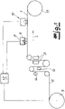
- the coating unit 6 or the two coating units 6 for the material web 2 follows in the 1 a crosslinking unit 7 in the processing direction indicated by an arrow or in the longitudinal direction L of the material web 2.
- the crosslinking unit 7 has UV lamps or UV LEDs, with the help of which the adhesive strips 4 applied to the respective surface of the material web 2 can be applied if necessary be networked. This means that the crosslinking unit 7 is to be considered as an option in the present case.
- the crosslinking unit 7 is designed in two parts, assigned to the respective surface of the material web 2 . This can be attributed to the fact that, according to the exemplary embodiment, both surfaces of the web of material 2 are equipped with associated adhesive strips 4 .
- the processing direction or longitudinal direction L of the material web 2 can be seen in the overview drawing according to FIG 1 first a sensor 8, 9, the function and characteristics of which will be explained in more detail below.
- the sensor 8, 9 is followed by a cutting device 10, with the help of which in each case 2 to be recognized cuts in the longitudinal direction or longitudinal cuts S are introduced into the material web 2.
- the cutting device 10 has a cutter bar, which is suitable and provided for the storage of knives rotating about a transverse axis, as is the case in the prior art according to FIG EP 2 744 865 B1 shows and describes as an example.
- the individual adhesive tapes 1 are made up and can, for example, be received or wound up on a winding unit 11 .
- the material web 2 is one in which a polyester fabric web is supplied as the carrier strip material.
- the web of material 2 can also be a fleece web, a film web, a paper web, and combinations thereof.
- the material web 2 is scanned with the aid of the sensor 8 , 9 .
- the sensor 8 , 9 is provided and placed above a surface of the material web 2 .
- the surface of the material web 2 pointing upwards is scanned with the local adhesive strip 4, which of course only applies as an example.
- the sensor 8, 9 as a whole can emit signals to a control unit 12, which, according to the supervision, is shown in FIG 3 to a topological edge course A; K 1 , K 2 of the respective adhesive strip 4 correspond.
- K 1 , K 2 of the adhesive strip 4 is in the context of the representation after 3 and the exemplary embodiment, a distance A between two edges K 1 , K 2 and the associated values for the distance A in the longitudinal direction L of the material web 2.
- edge K 1 is according to the embodiment in the 3 meaning the left edge of the material web 2 in the feed direction or longitudinal direction L.
- the edge K 2 designates the right-hand edge in the running direction or longitudinal direction L of the adhesive strip 4 that is closest to the edge K 1 of the material web 2.
- the topological course of the edges A; K 1 , K 2 now reflect the values for the respective distance A between the two edges K 1 and K 2 , depending on the respective position of the material web 2 in the longitudinal direction L.
- the individual values for the distance A, which are dependent on the longitudinal direction L, are fed into the control unit 12 as signals from the sensor 8, 9.
- the course of the K 2 can be detected.
- the course of the edge K 1 of the material web 2 is determined and sent to the control unit 12 . From the two values for the position of the respective edge K 1 , K 2 depending on its position in comparison to the longitudinal direction L of the material web 2, the control unit 12 can determine the already described topological course of the edges A; Determine K 1 , K 2 .
- the senor 8, 9 is first of all equipped in such a way that it can scan the material web 2 for differences in contrast.
- the contrast differences are different values for the light reflection from the adhesive-free surface of the material web 2 on the one hand and the adhesive strips 4 on the other.
- the illumination source 9 is the camera 8, for example LEDs surrounding it in a ring shape, which in the present case emit long-wave light in the visible spectrum, for example red light.
- This red light from the illumination source 9 is reflected differently by the material web 2 .
- the material web 2 is largely opaque on its adhesive-free surface next to the adhesive strip 4, ie it has only low light reflection.
- the adhesive strip 4 ensures increased light reflection in the visible range, which can typically be attributed to its “silver character” when viewed from above.
- the sensor 8, 9 can use these contrast differences to draw conclusions about the course of the edge K 2 on the right in the feed direction or longitudinal direction L of the adhesive strip 4 examined.
- the overall distance A between the two edges K 1 , K 2 can be determined as a function of the position of the material web 2 transmit to the control unit 12 and evaluate here.
- the material web 2 has the same overall width throughout, so that fluctuations in the previously explained distance A are solely due to movements of the material web 2 in the 3 indicated transverse direction Q are due.
- the respective coating unit applying the adhesive strips 4 to the material web 2 is provided 6 designed so that the individual and in the 3 adhesive strips 4 shown in plan have a constant distance from each other. This is because at this point one or more respective nozzles are used for dispensing the adhesive, which are arranged and placed mechanically fixed to one another and at a fixed distance from one another in the respective coating unit 6 .
- the distance A between the left edge K 1 of the material web 2 in the running direction or longitudinal direction L in comparison to the right edge K 2 of the adhesive strip 4 adjacent to the edge K 1 can serve as a total measure and be used to determine how large any Displacement ⁇ q of the material web 2 in the transverse direction Q when passing through the device after 1 is measured.
- control unit 12 is embodied as a regulating unit 12 in the present case.
- the distance A in question or, overall, the topological course of the edge A functions; K 1 , K 2 as controlled variable.
- a target value for the distance A in question can be specified in the control unit or regulating unit 12 .
- the control unit 12 ensures that the material web 2 is tracked or aligned in the transverse direction.
- the sensor 8, 9 measures a distance A that is smaller by the amount ⁇ q than specified by the target value A, this corresponds to a corresponding movement of the unwinding unit 3 with the aid of the drive 14 in the opposite direction, i.e. in the present case in the feed direction or longitudinal direction L to the left in the transverse direction Q. This is also indicated by an arrow.
- the material web 2 in the exemplary embodiment is aligned in the transverse direction Q before or even during the cutting process using the cutting device 10 and after the material web 2 has been provided with the respective adhesive strip 4 using the sensor 8, 9 scanning the material web 2.
- the alignment in the transverse direction Q of the web of material 2 takes place in such a way that a longitudinal cut or the plurality of longitudinal cuts S produced with the aid of the cutting device 10 are introduced into the web of material 2 with precise positioning, as is shown in FIG 2 is shown.
- the web of material 2 is examined for contrast differences between the adhesive-free surface and the respective adhesive strip 4 for this purpose.
- the contrast differences shown which are evaluated using the sensor 8, 9, correspond to different light reflections from the adhesive-free surface on the one hand and the adhesive strip 4 on the other.
- the sensor 8, 9 determines the topological edge profile A from these contrast differences; K 1 , K 2 of the relevant adhesive strip 4 on the material web 2.
- the material web 2 moved in the transverse direction Q namely the unwinding unit 3 .
- the unwinding unit 3 is assigned the drive 14 which ensures a travel movement in the transverse direction Q of the material web 2 .
- each generated and in the 2 illustrated longitudinal section S at the edge of the associated adhesive strip 4 optionally taking into account a predetermined minimum distance T to the relevant edge K 2 of the adhesive strip 4 in the web of material 2.
- This minimum distance T ensures that when the rotating knives of the cutting device 10 are immersed, the knives in question do not come into contact with the respective adhesive strip 4 .
- the signals transmitted by the sensor 8, 9 to the control unit 12 are used to evaluate both the course of the edge K1 of the material web 2 as a whole and the edge K2 of the at least one adhesive strip 4 examined.
- all adhesive strips 4 on the 3 to detect the surface of the web of material shown using the sensor 8 , 9 .
- the respective edge profile K 2 of the associated adhesive strip 4 can be averaged in the control unit 12 .
- the adhesive strips 4 are applied to the surface of the material web 2 at a fixed distance from one another with the aid of the respective coating unit 6, such a measurement of a plurality of adhesive strips 4 is strictly speaking not necessary, although it is possible. - In principle, the device and the method can work continuously. However, discontinuous operation is also possible, although this is not shown.
Description
Die Erfindung betrifft ein Verfahren zur Herstellung eines Klebebandes mit folgenden Verfahrensschritten:
- es wird eine Materialbahn aus einem Trägerbandmaterial von einer Abwickeleinheit zugeführt;
- die zugeführte Materialbahn wird anschließend an zumindest einer Oberfläche in einer Beschichtungseinheit mit wenigstens einem Klebstoffstreifen ausgerüstet;
- die mit dem Klebstoffstreifen ausgerüstete Materialbahn wird nachfolgend mit der Hilfe einer Schneideinrichtung in zumindest zwei Längsstreifen geschnitten und zu einzelnen Klebebändern konfektioniert.
- a material web made of a carrier strip material is fed in from an unwinding unit;
- the supplied material web is then equipped with at least one adhesive strip on at least one surface in a coating unit;
- the web of material equipped with the adhesive strip is subsequently cut into at least two longitudinal strips with the aid of a cutting device and made up into individual adhesive tapes.
Ein Verfahren und eine zugehörige Vorrichtung der eingangs beschriebenen Ausprägung wird beispielsweise in der
Im Stand der Technik nach der
Bei einer anderen Vorgehensweise entsprechend der
Die auf diese Weise hergestellten Klebebänder sind unterschiedlich ausgelegt bzw. können unterschiedlich ausgebildet sein. So unterscheidet man in der Praxis Klebebänder für eine Linkswicklung von solchen für eine Rechtswicklung. Hierbei wird das fragliche Klebeband jeweils wendeiförmig um zusammenzufassende und zu ummantelnde elektrische Kabel herumgewickelt, um insgesamt einen Kabelsatz respektive Kabelbaum für automobile Anwendungen herstellen zu können. Das hat sich grundsätzlich bewährt.The adhesive tapes produced in this way are designed differently or can be designed differently. In practice, a distinction is made between adhesive tapes for left-hand winding and those for right-hand winding. In this case, the adhesive tape in question is wound helically around the electrical cables to be combined and sheathed in order to be able to produce a cable harness or cable harness for automotive applications overall. This has basically worked.
Vergleichbares wird in der
Dabei kann erneut zwischen Klebebändern für die Linkswicklung und solchen für die Rechtswicklung unterschieden werden.A distinction can again be made between adhesive tapes for left-hand winding and those for right-hand winding.
Die schließlich noch zu nennende
Der Stand der Technik hat sich grundsätzlich bewährt, wenn es darum geht, eine Materialbahn aus einem Trägerbandmaterial mit einem oder mehreren Klebstoffstreifen auszurüsten und dann in Längsrichtung zu den einzelnen Klebebändern zu konfektionieren. Allerdings werden beim gattungsbildenden Stand der Technik entsprechend der
Darüber hinaus wird bei dem weiteren Stand der Technik entsprechend der
Der Erfindung liegt das technische Problem zugrunde, ein derartiges Verfahren und eine zugehörige Einrichtung so weiterzuentwickeln, dass die Logistik und Verarbeitung vereinfacht sind und der jeweils erzeugte Klebstoffstreifen des Klebebandes eine definierte Position gegenüber dem Träger reproduzierbar aufweist.The invention is based on the technical problem of further developing such a method and an associated device in such a way that the logistics and processing are simplified and the adhesive strip of the adhesive tape produced in each case has a defined position relative to the carrier in a reproducible manner.
Zur Lösung dieser technischen Problemstellung ist ein gattungsgemäßes Verfahren zur Herstellung eines Klebebandes der eingangs beschriebenen Ausprägung im Rahmen der Erfindung dadurch gekennzeichnet, dass die Materialbahn vor oder beim Schneidvorgang und nach der Ausrüstung mit dem Klebstoffstreifen mithilfe eines die Materialbahn abtastenden Sensors in Querrichtung so ausgerichtet wird, dass ein jeweils mithilfe der Schneideinrichtung erzeugter Längsschnitt positionsgenau in die Materialbahn eingebracht wird und dazu ein an eine Steuereinheit angeschlossener Antrieb für die Abwickeleinheit im Vergleich zur Vorschubrichtung bzw. Längsrichtung in der Querrichtung bewegt wird.To solve this technical problem, a generic method for producing an adhesive tape of the type described at the outset is, within the scope of the invention, characterized in that the web of material is aligned in the transverse direction before or during the cutting process and after it has been provided with the adhesive strip using a sensor scanning the web of material that a longitudinal cut produced with the aid of the cutting device is introduced into the material web in a precisely positioned manner and for this purpose a drive for the unwinding unit connected to a control unit is moved in the transverse direction compared to the feed direction or longitudinal direction.
Dabei ist die Auslegung im Detail so getroffen, dass der Sensor die Materialbahn auf Kontrastunterschiede hin abtastet. Bei den zu ermittelnden Kontrastunterschieden handelt es sich vorteilhaft um unterschiedliche Lichtreflexionen von einerseits der (unbeschichteten) klebstofffreien Oberfläche der Materialbahn und andererseits dem Klebstoffstreifen meistens im sichtbaren Spektralbereich.The detailed design is such that the sensor scans the material web for differences in contrast. The contrast differences to be determined are advantageously different light reflections from, on the one hand, the (uncoated) adhesive-free surface of the material web and, on the other hand, the adhesive strip, mostly in the visible spectral range.
Das heißt, der Sensor nimmt einerseits die klebstofffreie Materialbahn und andererseits den Klebstoffstreifen bzw. die zugehörigen Lichtreflexionen auf. Aus unterschiedlichen Lichtreflexionen der klebstofffreien Oberfläche und des Klebstoffstreifens kann auf einen Kontrastunterschied rückgeschlossen werden und lässt sich im Ergebnis die genaue Position des Klebstoffstreifens und insbesondere sein Kantenverlauf im Vergleich zur in Längsrichtung durchlaufenden Materialbahn respektive beispielsweise zur Kante der Materialbahn exakt festhalten und vermessen. Dabei spielt es letztendlich keine Rolle, ob die klebstofffreie Oberfläche der Materialbahn selbst eine Beschichtung aufweist oder nicht. Entscheidend ist einzig und allein ein ausreichender Kontrast zwischen der klebstofffreien Oberfläche der Materialbahn und dem Klebstoffstreifen als solchen, und zwar im Hinblick auf Lichtreflexionen. Hierbei geht die Erfindung von der Erkenntnis aus, dass beispielsweise auf die Materialbahn geworfenes sichtbares Licht unterschiedlich reflektiert wird, und zwar einerseits an der klebstofffreien Oberfläche der Materialbahn und andererseits am Klebstoffstreifen bzw. dessen Oberfläche.This means that the sensor records the adhesive-free material web on the one hand and the adhesive strip or the associated light reflections on the other. From the different light reflections of the adhesive-free surface and the adhesive strip, a difference in contrast can be inferred and, as a result, the exact position of the adhesive strip and in particular its edge profile in comparison to the material web running in the longitudinal direction or, for example, to the edge of the material web can be precisely recorded and measured. Ultimately, it doesn't matter whether the adhesive-free surface of the material web itself has a coating or not. The sole decisive factor is sufficient contrast between the adhesive-free surface of the material web and the adhesive strip as such, specifically with regard to light reflections. The invention is based on the knowledge that, for example, visible light thrown onto the material web is reflected differently, on the one hand on the adhesive-free surface of the material web and on the other hand on the adhesive strip or its surface.
Im Allgemeinen wird in diesem Zusammenhang mit sichtbarem Licht gearbeitet, welches im langwelligen roten Bereich angesiedelt sein kann, weil die Materialbahn beispielsweise als schwarz eingefärbte Gewebebahn ausgebildet ist. Selbstverständlich kann auch mit Weißlicht oder kurzwelligem sichtbaren Licht an dieser Stelle gearbeitet werden. Es ist grundsätzlich sogar auch möglich, im nicht sichtbaren Bereich des elektromagnetischen Spektrums zu arbeiten, beispielsweise mit nicht sichtbarem Infrarotlicht, welches auf die Materialbahn gerichtet und einerseits von der klebstofffreien Oberfläche und andererseits den Klebstoffstreifen unterschiedlich reflektiert und mithilfe des Sensors ausgewertet wird.In general, visible light is used in this context, which can be located in the long-wave red range, because the web of material is designed, for example, as a web of fabric dyed black. Of course, white light or short-wave visible light can also be used at this point. In principle, it is even possible to work in the invisible range of the electromagnetic spectrum, for example with invisible infrared light, which is directed at the material web and reflected differently by the adhesive-free surface on the one hand and the adhesive strips on the other hand and evaluated with the help of the sensor.
So oder so kann der Sensor anhand der Kontrastunterschiede zwischen einerseits der klebstofffreien Oberfläche der Materialbahn und andererseits dem Klebstoffstreifen den topologischen Verlauf des Klebstoffstreifens an der Oberfläche der Materialbahn vermessen und beispielsweise einen jeweiligen Abstand der Kante des Klebstoffstreifens von der Kante der Materialbahn, also den jeweiligen Kantenverlauf, messtechnisch erfassen.Either way, the sensor can use the contrast differences between the adhesive-free surface of the material web on the one hand and the adhesive strip on the other to measure the topological course of the adhesive strip on the surface of the material web and, for example, a respective distance between the edge of the adhesive strip and the edge of the material web, i.e. the respective edge course , record metrologically.
Dabei wird meistens so vorgegangen, dass der Sensor aus den Kontrastunterschieden zwischen der klebstofffreien Oberfläche der Materialbahn und dem Klebstoffstreifen einen topologischen Kantenverlauf des Klebstoffstreifens auf der Materialbahn erfasst und für die weitere Verarbeitung vorgibt. Das wird erfindungsgemäß mithilfe der die Signale des Sensors auswertenden Steuereinheit realisiert und umgesetzt. Zu diesem Zweck wird die Materialbahn jeweils in Querrichtung verfahren.The procedure is usually such that the sensor detects a topological edge profile of the adhesive strip on the material web from the contrast differences between the adhesive-free surface of the material web and the adhesive strip and specifies it for further processing. According to the invention, this is realized and implemented with the aid of the control unit that evaluates the signals from the sensor. For this purpose, the web of material is moved in the transverse direction.
Außerdem wird so vorgegangen, dass der jeweils erzeugte Längsschnitt in der mit dem Klebstoffstreifen ausgerüsteten Materialbahn gegebenenfalls unter Berücksichtigung eines vorgegebenen Minimalabstandes zum Rand bzw. der Kante des Klebstoffstreifens in die Materialbahn eingebracht wird. Dabei fungieren im Allgemeinen die von dem fraglichen Sensor an die Steuereinheit übermittelten Signale für den Kantenverlauf des Klebstoffstreifens als Regelgröße für die Stellbewegung der Materialbahn in Querrichtung.In addition, the procedure is such that the respective longitudinal cut produced in the material web equipped with the adhesive strip is introduced into the material web, possibly taking into account a predetermined minimum distance from the edge or the edge of the adhesive strip. In this case, the signals transmitted by the sensor in question to the control unit for the course of the edge of the adhesive strip generally function as a controlled variable for the adjusting movement of the material web in the transverse direction.
Der Kantenverlauf des Klebstoffstreifens und folglich die Regelgröße wirkt dabei im Sinne einer Kreisstruktur und Gegenkopplung auf sich selbst zurück. Das heißt, je nach gemessenem Kantenverlauf und folglich der Regelgröße wird die Materialbahn entsprechend in Querrichtung bewegt, damit beispielsweise ein zuvor vorgegebener Kantenverlauf eingestellt und beibehalten wird. Je nach einer Abweichung des mithilfe des Sensors tatsächlich gemessenen Kantenverlaufes von dem vorgegebenen Kantenverlauf sorgt die Steuereinheit für eine entsprechende Stellbewegung dahingehend, dass die Materialbahn in Querrichtung bewegt wird.The course of the edges of the adhesive strip and consequently the controlled variable acts back on itself in the sense of a circular structure and negative feedback. This means that depending on the measured edge profile and consequently the controlled variable, the material web is moved in the transverse direction accordingly, so that, for example, a previously specified edge profile is set and maintained. Depending on a deviation from what is actually measured using the sensor Edge profile from the predetermined edge profile provides the control unit for a corresponding adjustment movement to the effect that the web of material is moved in the transverse direction.
Erfindungsgemäß erfolgt die Stellbewegung an der Materialbahn, und zwar in der Gestalt, dass die Materialbahn mit dem zugehörigen Antrieb ausgerüstet ist, um die gewünschte Bewegung in Querrichtung zu vollführen. Da als Schneideinrichtung typischerweise ein Messerbalken mit mehreren rotierbar am Messerbalken gelagerten Schneidmessern zum Einsatz kommt, wird die Schneideinrichtung bzw. der Messerbalken in der Regel ortsfest ausgelegt, wohingegen der Antrieb zur Querbewegung der Materialbahn eingesetzt wird. Dazu ist die die Materialbahn zuführende Abwickeleinheit erfindungsgemäß mit dem betreffenden Antrieb ausgerüstet. - Gegenstand der Erfindung ist auch eine Einrichtung zur Herstellung eines Klebebandes, die vorteilhaft zur Durchführung des zuvor beschriebenen Verfahrens geeignet und in den Ansprüchen 7 fortfolgende näher beschrieben wird.According to the invention, the adjusting movement takes place on the web of material in such a way that the web of material is equipped with the associated drive in order to carry out the desired movement in the transverse direction. Since the cutting device typically used is a knife bar with a plurality of cutting knives rotatably mounted on the knife bar, the cutting device or the knife bar is usually designed to be stationary, whereas the drive is used to move the material web transversely. For this purpose, the unwinding unit feeding the material web is equipped according to the invention with the relevant drive. The invention also relates to a device for producing an adhesive tape, which is advantageously suitable for carrying out the method described above and is described in more detail in claims 7 below.
Im Ergebnis werden ein Verfahren und eine zugehörige Einrichtung zur Herstellung eines Klebebandes vorgestellt, mit deren Hilfe die exakte Position und der exakte Kantenverlauf des Klebstoffstreifens auf dem solchermaßen hergestellten und konfektionierten Klebeband vermessen und vorgegeben werden können. Dadurch eröffnet die Erfindung die Möglichkeit, jeweils exakt gleiche Klebebänder augangsseitig der erfindungsgemäßen Einrichtung zur Verfügung zu stellen, die beispielhaft entweder für eine Linkswicklung oder für eine Rechtswicklung bei einem wendeiförmigen Wickelvorgang zur Herstellung eines Kabelbaumes eingesetzt werden können, wie dies im Stand der Technik bekannt ist und zuvor hinlänglich beschrieben wurde. Als Folge hiervon wird insgesamt die Logistik vereinfacht und lassen sich zum ersten Mal Klebebänder mit Klebstoffstreifen reproduzierbar ausrüsten, die besonders exakt gefertigt sind und folglich für die anschließende Umwicklung von Kabeln zu Kabelsätzen bzw. Kabelbäumen prädestiniert sind.As a result, a method and an associated device for producing an adhesive tape are presented, with the help of which the exact position and the exact course of the edges of the adhesive strip on the adhesive tape produced and assembled in this way can be measured and specified. The invention thus opens up the possibility of providing exactly the same adhesive tapes on the output side of the device according to the invention, which can be used, for example, either for a left-hand winding or for a right-hand winding in a helical winding process for producing a cable harness, as is known in the prior art and previously sufficiently described. As a result of this, the overall logistics are simplified and, for the first time, adhesive tapes can be reproducibly equipped with adhesive strips that are manufactured with particular precision and are therefore predestined for the subsequent wrapping of cables into cable harnesses or cable harnesses.
Grundsätzlich lassen sich die solchermaßen hergestellten Klebebänder natürlich auch im Zuge einer Längsummantelung um zusammenzufassende Kabel schlagen. Im Regelfall werden die nach dem zuvor beschriebenen Verfahren hergestellten Klebebänder jedoch wendeiförmig um die betreffenden Kabel herumgewickelt und der jeweils gewünschte Kabelbaum hergestellt. Hierin sind die wesentlichen Vorteile zu sehen.In principle, the adhesive tapes produced in this way can of course also be wrapped around cables to be combined in the course of a longitudinal sheathing. As a rule, however, the adhesive tapes produced by the method described above are wound helically around the cable in question and the cable harness desired in each case is produced. This is where the main advantages can be seen.
Im Folgenden wird die Erfindung anhand einer lediglich am Ausführungsbeispiel darstellenden Zeichnung näher erläutert; es zeigen:
-
Fig. 1 eine erfindungsgemäße Einrichtung zur Herstellung eines Klebebandes in einer Übersicht, -
Fig. 2 einen schematischen Querschnitt durch die Materialbahn im Zuge der Herstellung der einzelnen Klebebänder und -
Fig. 3 eine ausschnittsweise Aufsicht auf die Einrichtung nachFig. 1 .
-
1 an overview of a device according to the invention for producing an adhesive tape, -
2 a schematic cross section through the material web in the course of the production of the individual adhesive tapes and -
3 a sectional view of thefacility 1 .
In den Figuren ist eine Einrichtung zur Herstellung eines Klebebandes 1 dargestellt. Anhand der Schnittdarstellung in der
Man erkennt anhand der Schnittdarstellung in der
Nach dem Ausführungsbeispiel und nicht einschränkend sind die beiden Klebstoffstreifen 4 gleich ausgelegt und verfügen über eine Breite, die im Vergleich zur Gesamtbreite B des solchermaßen hergestellten Klebebandes 1 in etwa 20 % bis 50 % dieser Gesamtbreite B beträgt oder betragen kann. Der jeweilige Klebstoffstreifen 4 wird mit einer Beschichtungseinheit 6 auf die Materialbahn 2 aufgebracht. Dazu wird die Materialbahn 2 ausgehend von der Abwickeleinheit 3 zunächst einer ersten Beschichtungseinheit 6 für seine eine Oberfläche und daran anschließend einer weiteren zweiten Beschichtungseinheit 6 für die andere Oberfläche zugeführt. Selbstverständlich kann auch nur mit einer einzigen Beschichtungseinheit 6 gearbeitet werden, und zwar für den Fall, dass die Materialbahn 2 lediglich auf einer Oberfläche mit mehreren Klebstoffstreifen 4 ausgerüstet wird.According to the exemplary embodiment and without limitation, the two
Bei der Beschichtungseinheit 6 zur Ausrüstung der Materialbahn 2 an zumindest einer Oberfläche mit dem Klebstoffstreifen 4 bzw. den mehreren parallel zueinander verlaufenden Klebstoffstreifen 4 handelt es sich um eine solche, mit deren Hilfe der jeweilige Klebstoff durch Direktbeschichtung auf die Materialbahn 2 im Zuge eines Düsenauftrages aufgebracht wird. Dazu wird der flüssige Klebstoff mithilfe beispielsweise einer Pumpe durch eine Breitschlitzdüse gedrückt. Jedem der in der
Bei der Materialbahn 2 handelt es sich nicht einschränkend um eine Bahn aus einem Gewebe, insbesondere einem Polyestergewebe. Grundsätzlich kann die Materialbahn auch als Folienbahn, Laminat, Papierbahn etc. ausgebildet sein. Nach dem Ausführungsbeispiel kommt eine Materialbahn 2 aus einem Polyestergewebe zum Einsatz, welches aus eingefärbten Kett- und Schussfäden aufgebaut ist. Dementsprechend handelt es sich bei dem Träger 5 des solchermaßen hergestellten Klebebandes um einen Polyestergewebeträger.The
Tatsächlich mögen die fraglichen Kett- und Schussfäden im beschriebenen Beispielfall spinndüsengefärbt sein und über eine durchgängig gleiche Farbe, zum Beispiel schwarz, verfügen. Das gilt selbstverständlich nur beispielhaft, weshalb die fraglichen Fäden grundsätzlich auch orange oder anders eingefärbt sein können. Der Beschichtungseinheit 6 bzw. den beiden Beschichtungseinheiten 6 für die Materialbahn 2 folgt in der
Im Rahmen des Ausführungsbeispiels ist die Vernetzungseinheit 7 zweigeteilt der jeweiligen Oberfläche der Materialbahn 2 zugeordnet ausgebildet. Das lässt sich darauf zurückführen, dass nach dem Ausführungsbeispiel beide Oberflächen der Materialbahn 2 mit zugehörigen Klebstoffstreifen 4 ausgerüstet sind.Within the scope of the exemplary embodiment, the crosslinking unit 7 is designed in two parts, assigned to the respective surface of the
Selbstverständlich ist eine solche Zweiteilung entbehrlich, wenn nur eine Oberfläche der Materialbahn 2 Klebstoffstreifen 4 aufweist, was vorliegend nicht dargestellt ist.Of course, such a division into two is unnecessary if only one surface of the
In Verarbeitungsrichtung bzw. Längsrichtung L der Materialbahn 2 erkennt man in der Übersichtszeichnung nach der
Abschließend und der Schneideinrichtung 10 folgend sind die einzelnen Klebebänder 1 konfektioniert und können beispielsweise auf einer Aufwickeleinheit 11 aufgenommen bzw. aufgewickelt werden. - Wie bereits erläutert, handelt es sich bei der Materialbahn 2 um eine solche, bei der als Trägerbandmaterial eine Polyestergewebebahn zugeführt wird. Alternativ oder zusätzlich kann es sich bei der Materialbahn 2 auch um eine Vliesbahn, eine Folienbahn, eine Papierbahn sowie Kombinationen handeln.Finally, following the
Mithilfe des Sensors 8, 9 wird die Materialbahn 2 abgetastet. Dazu ist der Sensor 8, 9 oberhalb einer Oberfläche der Materialbahn 2 vorgesehen und platziert. Nach dem Ausführungsbeispiel und nicht einschränkend wird die nach oben hin weisende Oberfläche der Materialbahn 2 mit dem dortigen Klebstoffstreifen 4 abgetastet, was selbstverständlich nur beispielhaft gilt. Tatsächlich kann der Sensor 8, 9 insgesamt Signale an eine Steuereinheit 12 abgeben, die ausweislich der Aufsicht entsprechende Darstellung in der
Mit der Kante K1 ist nach dem Ausführungsbeispiel in der
Die einzelnen und von der Längsrichtung L abhängigen Werte für den Abstand A werden vom Sensor 8, 9 als Signale in die Steuereinheit 12 eingespeist. Tatsächlich kann mithilfe des Sensors 8, 9 der Verlauf der K2 erfasst werden. Mithilfe eines weiteren Sensors 13 wird dem gegenüber der Verlauf der Kante K1 der Materialbahn 2 ermittelt und an die Steuereinheit 12 gesendet. Aus den beiden Werten für die Position der jeweiligen Kante K1, K2 in Abhängigkeit von ihrer Position im Vergleich zur Längsrichtung L der Materialbahn 2 kann die Steuereinheit 12 den bereits beschriebenen topologischen Kantenverlauf A; K1, K2 ermitteln.The individual values for the distance A, which are dependent on the longitudinal direction L, are fed into the
Dazu ist zunächst einmal der Sensor 8, 9 so ausgerüstet, dass er die Materialbahn 2 auf Kontrastunterschiede hin abtasten kann. Bei den Kontrastunterschieden handelt es sich um unterschiedliche Werte für die Lichtreflexion von einerseits der klebstofffreien Oberfläche der Materialbahn 2 und andererseits den Klebstoffstreifen 4. Zu diesem Zweck ist der Sensor 8, 9 im Ausführungsbeispiel mit einer Kamera 8 und einer die Kamera 8 umgebenden Beleuchtungsquelle 9 ausgerüstet. Bei der Beleuchtungsquelle 9 handelt es sich vorliegend um die Kamera 8 beispielsweise ringförmig umgebende LEDs, die vorliegend langwelliges Licht in sichtbarem Spektrum abgeben, beispielsweise rotes Licht.For this purpose, the
Dieses rote Licht der Beleuchtungsquelle 9 wird von der Materialbahn 2 unterschiedlich reflektiert. Tatsächlich ist die Materialbahn 2 an ihrer klebstofffreien Oberfläche neben dem Klebstoffstreifen 4 größtenteils opak ausgelegt, weist also eine nur geringe Lichtreflexion auf. Demgegenüber sorgt der Klebstoffstreifen 4 für eine erhöhte Lichtreflexion im sichtbaren Bereich, was sich typischerweise auf seinen in Aufsicht "silbrigen Charakter" zurückführen lässt. Jedenfalls kann der Sensor 8, 9 aus diesen Kontrastunterschieden auf den Verlauf der in der Vorschubrichtung bzw. Längsrichtung L rechte Kante K2 des untersuchten Klebstoffstreifens 4 rückschließen. In Verbindung mit den zugehörigen und mithilfe des weiteren Sensors 13 ermittelten Werten für den Verlauf der Kante K1 der Materialbahn 2 in diesem Bereich lässt sich insgesamt der Abstand A zwischen den beiden Kanten K1, K2 in Abhängigkeit von der Position der Materialbahn 2 an die Steuereinheit 12 übermitteln und hier auswerten.This red light from the
Die Erfindung geht hierbei insgesamt von mehreren Erkenntnissen aus. Zunächst einmal verfügt die Materialbahn 2 über eine insgesamt durchgängig gleiche Breite, so dass Schwankungen des zuvor bereits erläuterten Abstandes A einzig und allein auf Bewegungen der Materialbahn 2 in der in
Tatsächlich ist die Steuereinheit 12 vorliegend als Regeleinheit 12 ausgebildet. Außerdem fungiert der fragliche Abstand A bzw. insgesamt der topologische Kantenverlauf A; K1, K2 als Regelgröße. Dazu kann in der Steuereinheit bzw. Regeleinheit 12 ein Sollwert für den fraglichen Abstand A vorgegeben werden. Weicht beispielsweise der tatsächlich gemessene Abstand um den Betrag Δq von dem Sollwert A ab, das heißt misst der Sensor 8, 9 in Verbindung mit dem Sensor 13 an der untersuchten Position der Materialbahn 2 einen Wert von ![]()
![]()
Misst der Sensor 8, 9 dagegen einen um den Betrag Δq geringeren Abstand A als vom Sollwert A vorgegeben, so korrespondiert hierzu eine entsprechende Bewegung der Abwickeleinheit 3 mithilfe des Antriebes 14 in der Gegenrichtung, das heißt vorliegend in der Vorschubrichtung bzw. Längsrichtung L nach links in Querrichtung Q. Das ist ebenfalls durch einen Pfeil angedeutet.If, on the other hand, the
Auf diese Weise wird die Materialbahn 2 im Ausführungsbeispiel vor oder auch noch beim Schneidvorgang mithilfe der Schneideinrichtung 10 und nach der Ausrüstung der Materialbahn 2 mit dem jeweiligen Klebstoffstreifen 4 mithilfe des die Materialbahn 2 abtastenden Sensors 8, 9 in der Querrichtung Q ausgerichtet. Die Ausrichtung in der Querrichtung Q der Materialbahn 2 erfolgt dabei der Gestalt, dass ein jeweils mithilfe der Schneideinrichtung 10 erzeugter Längsschnitt bzw. die mehreren Längsschnitte S jeweils positionsgenau in die Materialbahn 2 eingebracht werden, wie dies in der
Wie bereits erläutert, wird zu diesem Zweck die Materialbahn 2 auf Kontrastunterschiede zwischen der klebstofffreien Oberfläche und dem jeweiligen Klebstoffstreifen 4 hin untersucht. Die dargestellten Kontrastunterschiede, die mithilfe des Sensors 8, 9 ausgewertet werden, korrespondieren dabei zu unterschiedlichen Lichtreflexionen von einerseits der klebstofffreien Oberfläche und andererseits dem Klebstoffstreifen 4. Aus diesen Kontrastunterschieden ermittelt der Sensor 8, 9 den topologischen Kantenverlauf A; K1, K2 des betreffenden Klebstoffstreifens 4 auf der Materialbahn 2.As already explained, the web of
Um etwaige Abweichungen Δq in der Querrichtung Q von einem Sollwert für den Abstand A auszugleichen, wird im Ausführungsbeispiel die Materialbahn 2 in der Querrichtung Q verfahren, nämlich die Abwickeleinheit 3. Dazu ist der Abwickeleinheit 3 der Antrieb 14 zugeordnet, welcher für eine Fahrbewegung in der Querrichtung Q der Materialbahn 2 sorgt.In order to compensate for any deviations Δq in the transverse direction Q from a target value for the distance A, the
Darüber hinaus besteht die grundsätzliche Möglichkeit, den jeweils erzeugten und in der
Jedenfalls werden die von dem Sensor 8, 9 an die Steuereinheit 12 übermittelten Signale zur Auswertung sowohl des Verlaufs der Kante K1 der Materialbahn 2 insgesamt als auch der Kante K2 des zumindest einen untersuchten Klebstoffstreifens 4 genutzt. Selbstverständlich liegt es im Rahmen der Erfindung, sämtliche Klebstoffstreifen 4 auf der in der
Da im Regelfall die Klebstoffstreifen 4 mit festem Abstand zueinander auf die Oberfläche der Materialbahn 2 mithilfe der jeweiligen Beschichtungseinheit 6 aufgebracht werden, ist eine solche Messung mehrerer Klebstoffstreifen 4 streng genommen nicht erforderlich, wenngleich möglich. - Grundsätzlich können die Einrichtung und das Verfahren kontinuierlich arbeiten. Es ist aber auch ein diskontinuierlicher Betrieb möglich, was jedoch nicht dargestellt ist.Since, as a rule, the
Claims (9)
- Method for producing an adhesive tape (1) with the following method steps:1.1) a material web (2) made of a carrier tape material is supplied from an unwinding unit (3);1.2) at least one adhesive strip (4) is then applied to at least one surface of the supplied material web (2) in a coating unit (6);1.3) the material web (2) with the applied adhesive strip (4) is then cut into at least two lengthwise strips with the aid of a cutting device (10) and assembled to form the individual adhesive tapes (1) ;characterized in that1.4) before or during the cutting process according to 1.3) and after application of the adhesive strip (4) according to 1.2), the material web (2) is aligned in the transverse direction (Q) in such manner by means of a sensor (8, 9) that scans the material web (2) that a precisely positioned lengthwise cut (S) created in each case with the cutting device (10) is introduced into the material web (2), and for this purpose1.5) a drive (14) for the unwinding unit (3) connected to a control unit (12) is moved in the transverse direction (Q) relative to the direction of advance or lengthwise direction (L).
- Method according to Claim 1, characterized in that the sensor (8, 9) scans the material web (2) for contrast differences.
- Method according to Claim 2, characterized in that the contrast differences are differing light reflections from the surface of the material web (2) with no adhesive on the one hand and the adhesive strip (4) on the other.
- Method according to any one of Claims 1 to 3, characterized in that the sensor (8, 9) captures a topological edge course (A; K1, K2) of the adhesive strip (4) on the material web (2) from the contrast differences between the surface of the material web (2) without adhesive and the adhesive strip (4) in conjunction with a control unit (12) that evaluates the signal values thereof.
- Method according to any one of Claims 1 to 4, characterized in that each lengthwise cut (S) created is introduced into the material web (2) on the border of the adhesive strip (4), optionally taking into account a predefined minimum distance (T) from the edge (K2) of the adhesive strip (4).
- Method according to any one of Claims 1 to 5, characterized in that the signals for the edge course (A; K1, K2) of the adhesive strip (4) transmitted by the sensor (8, 9) to the control unit (12) function as a control variable for an adjusting movement of the material web (2) in the transverse direction (Q).
- Device for producing an adhesive tape (1), in particular for performing the method according to any one of Claims 1 to 6, having an unwinding unit (3) which feeds a material web (2) from a carrier tape material, further having a coating unit (6) for applying at least one adhesive strip (4) to at least one surface of the material web (2), and having a cutting device (10) which cuts the material web (2) with the adhesive strip (4) applied into at least two lengthwise strips, which are finally assembled to form the adhesive tape (1) in question,
characterized in that
a sensor (8, 9) is provided, which scans the material web (2) and from which the signals are evaluated by a control unit (12) for the purpose of aligning the material web (2) in the transverse direction (Q) in order to introduce the lengthwise cuts (S) into the material web (2), which are each introduced with precise positioning with the aid of the cutting device (10), and for this purpose a drive (14) for the unwinding unit (3) which is connected to the control unit (12) is moved in the transverse direction (Q) relative to the direction of direction of advance or lengthwise direction (L). - Device according to Claim 7, characterized in that the sensor (8, 9) is designed as an optical sensor (8, 9) which scans contrast differences in the material web (2) in the visible spectrum.
- Device according to Claim 8, characterized in that the optical sensor (8, 9) includes a camera (8).
Applications Claiming Priority (2)
| Application Number | Priority Date | Filing Date | Title |
|---|---|---|---|
| DE102017120419.9A DE102017120419A1 (en) | 2017-09-05 | 2017-09-05 | Method and device for producing an adhesive tape |
| PCT/EP2018/072646 WO2019048232A1 (en) | 2017-09-05 | 2018-08-22 | Method and device for producing an adhesive tape |
Publications (2)
| Publication Number | Publication Date |
|---|---|
| EP3679102A1 EP3679102A1 (en) | 2020-07-15 |
| EP3679102B1 true EP3679102B1 (en) | 2022-04-27 |
Family
ID=63364061
Family Applications (1)
| Application Number | Title | Priority Date | Filing Date |
|---|---|---|---|
| EP18759289.4A Active EP3679102B1 (en) | 2017-09-05 | 2018-08-22 | Method and device for producing an adhesive tape |
Country Status (5)
| Country | Link |
|---|---|
| US (1) | US11498791B2 (en) |
| EP (1) | EP3679102B1 (en) |
| CN (1) | CN111065702B (en) |
| DE (1) | DE102017120419A1 (en) |
| WO (1) | WO2019048232A1 (en) |
Families Citing this family (2)
| Publication number | Priority date | Publication date | Assignee | Title |
|---|---|---|---|---|
| DE102017120419A1 (en) * | 2017-09-05 | 2019-03-07 | Certoplast Technische Klebebänder Gmbh | Method and device for producing an adhesive tape |
| CN112357653B (en) * | 2021-01-12 | 2021-04-23 | 潍坊科技学院 | Sheet metal winding and conveying device with anticorrosive paint spraying mechanism |
Family Cites Families (25)
| Publication number | Priority date | Publication date | Assignee | Title |
|---|---|---|---|---|
| US4460634A (en) * | 1979-12-29 | 1984-07-17 | Masaaki Hasegawa | Adhesive sheet and method for manufacturing the same |
| GB2152005B (en) * | 1983-12-23 | 1987-07-15 | Photoleaflets | Self-adhesive prints or labels |
| JPH0679695A (en) * | 1992-08-28 | 1994-03-22 | New Oji Paper Co Ltd | Cutting method for pressure adhesive paper |
| US5725320A (en) * | 1995-05-04 | 1998-03-10 | Intermec Corporation | Linerless media and cutting apparatus for minimizing adhesive problems when cutting the media |
| US5730354A (en) * | 1996-07-12 | 1998-03-24 | Kt Industries Inc. | Printed tear tape |
| US6268032B1 (en) * | 1997-10-03 | 2001-07-31 | 3M Innovative Properties Company | Repositionable note sheets and method of formation thereof |
| EP1041131A1 (en) * | 1998-02-02 | 2000-10-04 | Tsujiden Co., Ltd. | Double faced tape, method of and apparatus for manufacturing same |
| US6394330B1 (en) * | 1998-08-13 | 2002-05-28 | 3M Innovative Properties Company | Method for slitting and processing a web into plural use supply forms |
| DE10001816C1 (en) * | 1999-11-13 | 2001-06-21 | Erhardt & Leimer Gmbh | Device and method for guiding a cross-stable web |
| DE10042732A1 (en) | 2000-08-31 | 2002-03-28 | Tesa Ag | Process for sheathing elongated goods, such as in particular cable sets with an adhesive tape |
| GB0106816D0 (en) * | 2001-03-19 | 2001-05-09 | Rue De Int Ltd | Sheet handling apparatus and method |
| JP2005177617A (en) * | 2003-12-19 | 2005-07-07 | Toshiba Corp | Paper sheet cutting device |
| WO2007117562A2 (en) * | 2006-04-05 | 2007-10-18 | Mikkelsen Graphic Engineering, Inc. | Method and apparatus for fray-free textile cutting |
| US7615128B2 (en) * | 2006-04-05 | 2009-11-10 | Mikkelsen Graphic Engineering, Inc. | Method and apparatus for fray-free textile cutting |
| WO2009118826A1 (en) * | 2008-03-25 | 2009-10-01 | 株式会社イトウ六 | Process for producing long adhesive tape roll of extra fine width and apparatus therefor |
| CN101559889B (en) * | 2008-04-16 | 2011-06-01 | 日东电工株式会社 | Roller-shaped coiling set and method for production thereof |
| DE202010014239U1 (en) | 2010-10-14 | 2010-12-30 | Certoplast Vorwerk & Sohn Gmbh | Adhesive tape as well as hose cover made of the adhesive tape |
| CN103732519A (en) * | 2011-06-10 | 2014-04-16 | 毕索龙欧洲有限公司 | Printer for printing on a tape coated with adhesive on one side |
| DE102011052821A1 (en) * | 2011-08-18 | 2013-02-21 | Certoplast Vorwerk & Sohn Gmbh | Method and device for producing an adhesive tape |
| JP2014086478A (en) * | 2012-10-22 | 2014-05-12 | Nitto Denko Corp | Method of manufacturing image sensor and lamination heat-resistant protective tape for use therein |
| GB2523389A (en) * | 2014-02-24 | 2015-08-26 | Essentra Packaging & Security Ltd | Method and apparatus for manufacturing a tape |
| GB2523390B (en) * | 2014-02-24 | 2017-11-29 | Essentra Packaging & Security Ltd | Method and apparatus for manufacturing a tape |
| DE202015103713U1 (en) * | 2015-07-15 | 2015-07-27 | Certoplast Technische Klebebänder Gmbh | duct tape |
| CN206123749U (en) * | 2016-08-30 | 2017-04-26 | 浙江绿洲胶粘制品有限公司 | Adhesive tape dividing and cutting machine |
| DE102017120419A1 (en) * | 2017-09-05 | 2019-03-07 | Certoplast Technische Klebebänder Gmbh | Method and device for producing an adhesive tape |
-
2017
- 2017-09-05 DE DE102017120419.9A patent/DE102017120419A1/en not_active Withdrawn
-
2018
- 2018-08-22 US US16/639,276 patent/US11498791B2/en active Active
- 2018-08-22 EP EP18759289.4A patent/EP3679102B1/en active Active
- 2018-08-22 CN CN201880057502.4A patent/CN111065702B/en active Active
- 2018-08-22 WO PCT/EP2018/072646 patent/WO2019048232A1/en unknown
Also Published As
| Publication number | Publication date |
|---|---|
| WO2019048232A1 (en) | 2019-03-14 |
| CN111065702A (en) | 2020-04-24 |
| DE102017120419A1 (en) | 2019-03-07 |
| US11498791B2 (en) | 2022-11-15 |
| CN111065702B (en) | 2022-06-03 |
| US20200247635A1 (en) | 2020-08-06 |
| WO2019048232A8 (en) | 2019-05-16 |
| EP3679102A1 (en) | 2020-07-15 |
Similar Documents
| Publication | Publication Date | Title |
|---|---|---|
| DE2424041C2 (en) | Fiber optic tape and method of making it | |
| DE3218304A1 (en) | DEVICE FOR SEPARATING CONTINUOUS FORM SETS OR THE LIKE. | |
| EP3679102B1 (en) | Method and device for producing an adhesive tape | |
| EP0360108A1 (en) | Process and apparatus for delivering labels | |
| EP0401597A2 (en) | Control arrangements for cutting a web according to the length | |
| EP2401220A1 (en) | Method and device for adhering an edge of a laminar object | |
| DE102017105154B4 (en) | Apparatus and method for severing a tape into a plurality of individual tape pieces | |
| WO2020225369A1 (en) | Forming machine and method for producing bent parts from an insulated elongate material having stripped ends | |
| DE3203162A1 (en) | METHOD AND DEVICE FOR LABELING OBJECTS | |
| EP0220415A2 (en) | Apparatus for cutting sheets | |
| DE19519584A1 (en) | Continuous system for cutting and gluing flat material | |
| EP0381112B1 (en) | Method and apparatus for working webs in register, especially when producing safety yarns | |
| EP3403557A1 (en) | Device for dispensing paper sections of predetermined lengths | |
| CH690323A5 (en) | Method and apparatus for cutting continuously demanded, in particular of paper products flochigen. | |
| DE102008061165B4 (en) | Semiconductor device with a film and method and apparatus for producing such | |
| DE2421376A1 (en) | METHOD OF MANUFACTURING ELECTRIC COILS | |
| EP0401289A1 (en) | Strip-type tag label and device for producing it | |
| EP0931631A2 (en) | Edge trimming apparatus for web material | |
| DE2409608C2 (en) | Device for treating a strip of material made of compressible fiber material and the associated method | |
| EP2919993B1 (en) | Monitoring system for the alignment of an inline printing press | |
| EP1542859B1 (en) | Method for the preparation of film webs | |
| EP0536685A1 (en) | Apparatus for material adapted perforating of multi-part business forms | |
| WO2023220763A1 (en) | Optical fibre ribbon and method for the production thereof | |
| DE1113728B (en) | Process and production facility for the continuous production of glued or molded ribbon cables with molded soldering pins | |
| DE2553725B1 (en) | Method and apparatus for manufacturing a flat ribbon cable |
Legal Events
| Date | Code | Title | Description |
|---|---|---|---|
| STAA | Information on the status of an ep patent application or granted ep patent |
Free format text: STATUS: UNKNOWN |
|
| STAA | Information on the status of an ep patent application or granted ep patent |
Free format text: STATUS: THE INTERNATIONAL PUBLICATION HAS BEEN MADE |
|
| PUAI | Public reference made under article 153(3) epc to a published international application that has entered the european phase |
Free format text: ORIGINAL CODE: 0009012 |
|
| STAA | Information on the status of an ep patent application or granted ep patent |
Free format text: STATUS: REQUEST FOR EXAMINATION WAS MADE |
|
| 17P | Request for examination filed |
Effective date: 20200218 |
|
| AK | Designated contracting states |
Kind code of ref document: A1 Designated state(s): AL AT BE BG CH CY CZ DE DK EE ES FI FR GB GR HR HU IE IS IT LI LT LU LV MC MK MT NL NO PL PT RO RS SE SI SK SM TR |
|
| AX | Request for extension of the european patent |
Extension state: BA ME |
|
| DAV | Request for validation of the european patent (deleted) | ||
| DAX | Request for extension of the european patent (deleted) | ||
| GRAP | Despatch of communication of intention to grant a patent |
Free format text: ORIGINAL CODE: EPIDOSNIGR1 |
|
| STAA | Information on the status of an ep patent application or granted ep patent |
Free format text: STATUS: GRANT OF PATENT IS INTENDED |
|
| RIC1 | Information provided on ipc code assigned before grant |
Ipc: B65H 23/032 20060101ALI20211124BHEP Ipc: B65H 18/10 20060101ALI20211124BHEP Ipc: B26D 7/26 20060101ALI20211124BHEP Ipc: C09J 7/30 20180101AFI20211124BHEP |
|
| INTG | Intention to grant announced |
Effective date: 20211222 |
|
| GRAS | Grant fee paid |
Free format text: ORIGINAL CODE: EPIDOSNIGR3 |
|
| GRAA | (expected) grant |
Free format text: ORIGINAL CODE: 0009210 |
|
| STAA | Information on the status of an ep patent application or granted ep patent |
Free format text: STATUS: THE PATENT HAS BEEN GRANTED |
|
| AK | Designated contracting states |
Kind code of ref document: B1 Designated state(s): AL AT BE BG CH CY CZ DE DK EE ES FI FR GB GR HR HU IE IS IT LI LT LU LV MC MK MT NL NO PL PT RO RS SE SI SK SM TR |
|
| REG | Reference to a national code |
Ref country code: GB Ref legal event code: FG4D Free format text: NOT ENGLISH |
|
| REG | Reference to a national code |
Ref country code: CH Ref legal event code: EP |
|
| REG | Reference to a national code |
Ref country code: AT Ref legal event code: REF Ref document number: 1486941 Country of ref document: AT Kind code of ref document: T Effective date: 20220515 |
|
| REG | Reference to a national code |
Ref country code: DE Ref legal event code: R096 Ref document number: 502018009516 Country of ref document: DE |
|
| REG | Reference to a national code |
Ref country code: IE Ref legal event code: FG4D Free format text: LANGUAGE OF EP DOCUMENT: GERMAN |
|
| REG | Reference to a national code |
Ref country code: LT Ref legal event code: MG9D |
|
| REG | Reference to a national code |
Ref country code: NL Ref legal event code: MP Effective date: 20220427 |
|
| PG25 | Lapsed in a contracting state [announced via postgrant information from national office to epo] |
Ref country code: NL Free format text: LAPSE BECAUSE OF FAILURE TO SUBMIT A TRANSLATION OF THE DESCRIPTION OR TO PAY THE FEE WITHIN THE PRESCRIBED TIME-LIMIT Effective date: 20220427 |
|
| PG25 | Lapsed in a contracting state [announced via postgrant information from national office to epo] |
Ref country code: SE Free format text: LAPSE BECAUSE OF FAILURE TO SUBMIT A TRANSLATION OF THE DESCRIPTION OR TO PAY THE FEE WITHIN THE PRESCRIBED TIME-LIMIT Effective date: 20220427 Ref country code: PT Free format text: LAPSE BECAUSE OF FAILURE TO SUBMIT A TRANSLATION OF THE DESCRIPTION OR TO PAY THE FEE WITHIN THE PRESCRIBED TIME-LIMIT Effective date: 20220829 Ref country code: NO Free format text: LAPSE BECAUSE OF FAILURE TO SUBMIT A TRANSLATION OF THE DESCRIPTION OR TO PAY THE FEE WITHIN THE PRESCRIBED TIME-LIMIT Effective date: 20220727 Ref country code: LT Free format text: LAPSE BECAUSE OF FAILURE TO SUBMIT A TRANSLATION OF THE DESCRIPTION OR TO PAY THE FEE WITHIN THE PRESCRIBED TIME-LIMIT Effective date: 20220427 Ref country code: HR Free format text: LAPSE BECAUSE OF FAILURE TO SUBMIT A TRANSLATION OF THE DESCRIPTION OR TO PAY THE FEE WITHIN THE PRESCRIBED TIME-LIMIT Effective date: 20220427 Ref country code: GR Free format text: LAPSE BECAUSE OF FAILURE TO SUBMIT A TRANSLATION OF THE DESCRIPTION OR TO PAY THE FEE WITHIN THE PRESCRIBED TIME-LIMIT Effective date: 20220728 Ref country code: FI Free format text: LAPSE BECAUSE OF FAILURE TO SUBMIT A TRANSLATION OF THE DESCRIPTION OR TO PAY THE FEE WITHIN THE PRESCRIBED TIME-LIMIT Effective date: 20220427 Ref country code: ES Free format text: LAPSE BECAUSE OF FAILURE TO SUBMIT A TRANSLATION OF THE DESCRIPTION OR TO PAY THE FEE WITHIN THE PRESCRIBED TIME-LIMIT Effective date: 20220427 Ref country code: BG Free format text: LAPSE BECAUSE OF FAILURE TO SUBMIT A TRANSLATION OF THE DESCRIPTION OR TO PAY THE FEE WITHIN THE PRESCRIBED TIME-LIMIT Effective date: 20220727 |
|
| PG25 | Lapsed in a contracting state [announced via postgrant information from national office to epo] |
Ref country code: RS Free format text: LAPSE BECAUSE OF FAILURE TO SUBMIT A TRANSLATION OF THE DESCRIPTION OR TO PAY THE FEE WITHIN THE PRESCRIBED TIME-LIMIT Effective date: 20220427 Ref country code: PL Free format text: LAPSE BECAUSE OF FAILURE TO SUBMIT A TRANSLATION OF THE DESCRIPTION OR TO PAY THE FEE WITHIN THE PRESCRIBED TIME-LIMIT Effective date: 20220427 Ref country code: LV Free format text: LAPSE BECAUSE OF FAILURE TO SUBMIT A TRANSLATION OF THE DESCRIPTION OR TO PAY THE FEE WITHIN THE PRESCRIBED TIME-LIMIT Effective date: 20220427 Ref country code: IS Free format text: LAPSE BECAUSE OF FAILURE TO SUBMIT A TRANSLATION OF THE DESCRIPTION OR TO PAY THE FEE WITHIN THE PRESCRIBED TIME-LIMIT Effective date: 20220827 |
|
| REG | Reference to a national code |
Ref country code: DE Ref legal event code: R097 Ref document number: 502018009516 Country of ref document: DE |
|
| PG25 | Lapsed in a contracting state [announced via postgrant information from national office to epo] |
Ref country code: SM Free format text: LAPSE BECAUSE OF FAILURE TO SUBMIT A TRANSLATION OF THE DESCRIPTION OR TO PAY THE FEE WITHIN THE PRESCRIBED TIME-LIMIT Effective date: 20220427 Ref country code: SK Free format text: LAPSE BECAUSE OF FAILURE TO SUBMIT A TRANSLATION OF THE DESCRIPTION OR TO PAY THE FEE WITHIN THE PRESCRIBED TIME-LIMIT Effective date: 20220427 Ref country code: RO Free format text: LAPSE BECAUSE OF FAILURE TO SUBMIT A TRANSLATION OF THE DESCRIPTION OR TO PAY THE FEE WITHIN THE PRESCRIBED TIME-LIMIT Effective date: 20220427 Ref country code: EE Free format text: LAPSE BECAUSE OF FAILURE TO SUBMIT A TRANSLATION OF THE DESCRIPTION OR TO PAY THE FEE WITHIN THE PRESCRIBED TIME-LIMIT Effective date: 20220427 Ref country code: DK Free format text: LAPSE BECAUSE OF FAILURE TO SUBMIT A TRANSLATION OF THE DESCRIPTION OR TO PAY THE FEE WITHIN THE PRESCRIBED TIME-LIMIT Effective date: 20220427 Ref country code: CZ Free format text: LAPSE BECAUSE OF FAILURE TO SUBMIT A TRANSLATION OF THE DESCRIPTION OR TO PAY THE FEE WITHIN THE PRESCRIBED TIME-LIMIT Effective date: 20220427 |
|
| PLBE | No opposition filed within time limit |
Free format text: ORIGINAL CODE: 0009261 |
|
| STAA | Information on the status of an ep patent application or granted ep patent |
Free format text: STATUS: NO OPPOSITION FILED WITHIN TIME LIMIT |
|
| PG25 | Lapsed in a contracting state [announced via postgrant information from national office to epo] |
Ref country code: MC Free format text: LAPSE BECAUSE OF FAILURE TO SUBMIT A TRANSLATION OF THE DESCRIPTION OR TO PAY THE FEE WITHIN THE PRESCRIBED TIME-LIMIT Effective date: 20220427 Ref country code: AL Free format text: LAPSE BECAUSE OF FAILURE TO SUBMIT A TRANSLATION OF THE DESCRIPTION OR TO PAY THE FEE WITHIN THE PRESCRIBED TIME-LIMIT Effective date: 20220427 |
|
| REG | Reference to a national code |
Ref country code: CH Ref legal event code: PL |
|
| 26N | No opposition filed |
Effective date: 20230130 |
|
| PG25 | Lapsed in a contracting state [announced via postgrant information from national office to epo] |
Ref country code: LU Free format text: LAPSE BECAUSE OF NON-PAYMENT OF DUE FEES Effective date: 20220822 Ref country code: LI Free format text: LAPSE BECAUSE OF NON-PAYMENT OF DUE FEES Effective date: 20220831 Ref country code: CH Free format text: LAPSE BECAUSE OF NON-PAYMENT OF DUE FEES Effective date: 20220831 |
|
| REG | Reference to a national code |
Ref country code: BE Ref legal event code: MM Effective date: 20220831 |
|
| PG25 | Lapsed in a contracting state [announced via postgrant information from national office to epo] |
Ref country code: SI Free format text: LAPSE BECAUSE OF FAILURE TO SUBMIT A TRANSLATION OF THE DESCRIPTION OR TO PAY THE FEE WITHIN THE PRESCRIBED TIME-LIMIT Effective date: 20220427 |
|
| PG25 | Lapsed in a contracting state [announced via postgrant information from national office to epo] |
Ref country code: IE Free format text: LAPSE BECAUSE OF NON-PAYMENT OF DUE FEES Effective date: 20220822 |
|
| PG25 | Lapsed in a contracting state [announced via postgrant information from national office to epo] |
Ref country code: BE Free format text: LAPSE BECAUSE OF NON-PAYMENT OF DUE FEES Effective date: 20220831 |
|
| PGFP | Annual fee paid to national office [announced via postgrant information from national office to epo] |
Ref country code: IT Payment date: 20230825 Year of fee payment: 6 Ref country code: GB Payment date: 20230822 Year of fee payment: 6 |
|
| PGFP | Annual fee paid to national office [announced via postgrant information from national office to epo] |
Ref country code: FR Payment date: 20230828 Year of fee payment: 6 Ref country code: DE Payment date: 20230707 Year of fee payment: 6 |