EP3677921A1 - Une cartouche pour système de dosage numérique - Google Patents
Une cartouche pour système de dosage numérique Download PDFInfo
- Publication number
- EP3677921A1 EP3677921A1 EP19219773.9A EP19219773A EP3677921A1 EP 3677921 A1 EP3677921 A1 EP 3677921A1 EP 19219773 A EP19219773 A EP 19219773A EP 3677921 A1 EP3677921 A1 EP 3677921A1
- Authority
- EP
- European Patent Office
- Prior art keywords
- fluid
- droplet ejection
- open
- ejection cartridge
- cartridge
- Prior art date
- Legal status (The legal status is an assumption and is not a legal conclusion. Google has not performed a legal analysis and makes no representation as to the accuracy of the status listed.)
- Granted
Links
- 239000012530 fluid Substances 0.000 claims abstract description 324
- 239000000758 substrate Substances 0.000 claims abstract description 71
- 239000004065 semiconductor Substances 0.000 claims abstract description 27
- 238000000034 method Methods 0.000 claims abstract description 20
- 238000004891 communication Methods 0.000 claims abstract description 4
- 239000011159 matrix material Substances 0.000 claims description 22
- 230000007246 mechanism Effects 0.000 claims description 13
- 238000013519 translation Methods 0.000 claims description 12
- 230000003213 activating effect Effects 0.000 claims description 4
- 238000004458 analytical method Methods 0.000 description 10
- 239000008280 blood Substances 0.000 description 4
- 210000004369 blood Anatomy 0.000 description 4
- 239000011521 glass Substances 0.000 description 3
- 230000008901 benefit Effects 0.000 description 2
- 238000005516 engineering process Methods 0.000 description 2
- 238000004519 manufacturing process Methods 0.000 description 2
- 239000000463 material Substances 0.000 description 2
- 238000012986 modification Methods 0.000 description 2
- 230000004048 modification Effects 0.000 description 2
- 238000002360 preparation method Methods 0.000 description 2
- 230000004913 activation Effects 0.000 description 1
- 230000008859 change Effects 0.000 description 1
- 230000005465 channeling Effects 0.000 description 1
- 238000004737 colorimetric analysis Methods 0.000 description 1
- 238000011109 contamination Methods 0.000 description 1
- 230000003247 decreasing effect Effects 0.000 description 1
- 230000008021 deposition Effects 0.000 description 1
- 239000003814 drug Substances 0.000 description 1
- 229940079593 drug Drugs 0.000 description 1
- 230000007717 exclusion Effects 0.000 description 1
- 238000002474 experimental method Methods 0.000 description 1
- 238000010304 firing Methods 0.000 description 1
- -1 for example Substances 0.000 description 1
- 230000004886 head movement Effects 0.000 description 1
- 230000036541 health Effects 0.000 description 1
- 238000007641 inkjet printing Methods 0.000 description 1
- 230000010354 integration Effects 0.000 description 1
- 238000005497 microtitration Methods 0.000 description 1
- 239000000203 mixture Substances 0.000 description 1
- 238000000206 photolithography Methods 0.000 description 1
- 230000008569 process Effects 0.000 description 1
- 238000012163 sequencing technique Methods 0.000 description 1
- 238000010186 staining Methods 0.000 description 1
- 239000000126 substance Substances 0.000 description 1
Images


Classifications
-
- B—PERFORMING OPERATIONS; TRANSPORTING
- B01—PHYSICAL OR CHEMICAL PROCESSES OR APPARATUS IN GENERAL
- B01L—CHEMICAL OR PHYSICAL LABORATORY APPARATUS FOR GENERAL USE
- B01L3/00—Containers or dishes for laboratory use, e.g. laboratory glassware; Droppers
- B01L3/02—Burettes; Pipettes
- B01L3/0241—Drop counters; Drop formers
- B01L3/0268—Drop counters; Drop formers using pulse dispensing or spraying, eg. inkjet type, piezo actuated ejection of droplets from capillaries
-
- G—PHYSICS
- G01—MEASURING; TESTING
- G01N—INVESTIGATING OR ANALYSING MATERIALS BY DETERMINING THEIR CHEMICAL OR PHYSICAL PROPERTIES
- G01N35/00—Automatic analysis not limited to methods or materials provided for in any single one of groups G01N1/00 - G01N33/00; Handling materials therefor
- G01N35/10—Devices for transferring samples or any liquids to, in, or from, the analysis apparatus, e.g. suction devices, injection devices
- G01N35/1065—Multiple transfer devices
- G01N35/1074—Multiple transfer devices arranged in a two-dimensional array
-
- G—PHYSICS
- G01—MEASURING; TESTING
- G01N—INVESTIGATING OR ANALYSING MATERIALS BY DETERMINING THEIR CHEMICAL OR PHYSICAL PROPERTIES
- G01N35/00—Automatic analysis not limited to methods or materials provided for in any single one of groups G01N1/00 - G01N33/00; Handling materials therefor
- G01N35/10—Devices for transferring samples or any liquids to, in, or from, the analysis apparatus, e.g. suction devices, injection devices
- G01N35/1009—Characterised by arrangements for controlling the aspiration or dispense of liquids
- G01N35/1016—Control of the volume dispensed or introduced
-
- G—PHYSICS
- G01—MEASURING; TESTING
- G01N—INVESTIGATING OR ANALYSING MATERIALS BY DETERMINING THEIR CHEMICAL OR PHYSICAL PROPERTIES
- G01N35/00—Automatic analysis not limited to methods or materials provided for in any single one of groups G01N1/00 - G01N33/00; Handling materials therefor
- G01N35/10—Devices for transferring samples or any liquids to, in, or from, the analysis apparatus, e.g. suction devices, injection devices
- G01N35/1065—Multiple transfer devices
- G01N35/1067—Multiple transfer devices for transfer to or from containers having different spacing
-
- G—PHYSICS
- G01—MEASURING; TESTING
- G01N—INVESTIGATING OR ANALYSING MATERIALS BY DETERMINING THEIR CHEMICAL OR PHYSICAL PROPERTIES
- G01N35/00—Automatic analysis not limited to methods or materials provided for in any single one of groups G01N1/00 - G01N33/00; Handling materials therefor
- G01N35/10—Devices for transferring samples or any liquids to, in, or from, the analysis apparatus, e.g. suction devices, injection devices
- G01N35/1081—Devices for transferring samples or any liquids to, in, or from, the analysis apparatus, e.g. suction devices, injection devices characterised by the means for relatively moving the transfer device and the containers in an horizontal plane
- G01N35/1083—Devices for transferring samples or any liquids to, in, or from, the analysis apparatus, e.g. suction devices, injection devices characterised by the means for relatively moving the transfer device and the containers in an horizontal plane with one horizontal degree of freedom
-
- B—PERFORMING OPERATIONS; TRANSPORTING
- B01—PHYSICAL OR CHEMICAL PROCESSES OR APPARATUS IN GENERAL
- B01J—CHEMICAL OR PHYSICAL PROCESSES, e.g. CATALYSIS OR COLLOID CHEMISTRY; THEIR RELEVANT APPARATUS
- B01J2219/00—Chemical, physical or physico-chemical processes in general; Their relevant apparatus
- B01J2219/00274—Sequential or parallel reactions; Apparatus and devices for combinatorial chemistry or for making arrays; Chemical library technology
- B01J2219/00277—Apparatus
- B01J2219/00351—Means for dispensing and evacuation of reagents
- B01J2219/00389—Feeding through valves
- B01J2219/00391—Rotary valves
- B01J2219/00394—Rotary valves in multiple arrangements
-
- B—PERFORMING OPERATIONS; TRANSPORTING
- B01—PHYSICAL OR CHEMICAL PROCESSES OR APPARATUS IN GENERAL
- B01J—CHEMICAL OR PHYSICAL PROCESSES, e.g. CATALYSIS OR COLLOID CHEMISTRY; THEIR RELEVANT APPARATUS
- B01J2219/00—Chemical, physical or physico-chemical processes in general; Their relevant apparatus
- B01J2219/00274—Sequential or parallel reactions; Apparatus and devices for combinatorial chemistry or for making arrays; Chemical library technology
- B01J2219/0068—Means for controlling the apparatus of the process
- B01J2219/00695—Synthesis control routines, e.g. using computer programs
-
- B—PERFORMING OPERATIONS; TRANSPORTING
- B01—PHYSICAL OR CHEMICAL PROCESSES OR APPARATUS IN GENERAL
- B01L—CHEMICAL OR PHYSICAL LABORATORY APPARATUS FOR GENERAL USE
- B01L2200/00—Solutions for specific problems relating to chemical or physical laboratory apparatus
- B01L2200/06—Fluid handling related problems
- B01L2200/0642—Filling fluids into wells by specific techniques
-
- B—PERFORMING OPERATIONS; TRANSPORTING
- B01—PHYSICAL OR CHEMICAL PROCESSES OR APPARATUS IN GENERAL
- B01L—CHEMICAL OR PHYSICAL LABORATORY APPARATUS FOR GENERAL USE
- B01L2300/00—Additional constructional details
- B01L2300/08—Geometry, shape and general structure
- B01L2300/0809—Geometry, shape and general structure rectangular shaped
- B01L2300/0829—Multi-well plates; Microtitration plates
-
- B—PERFORMING OPERATIONS; TRANSPORTING
- B01—PHYSICAL OR CHEMICAL PROCESSES OR APPARATUS IN GENERAL
- B01L—CHEMICAL OR PHYSICAL LABORATORY APPARATUS FOR GENERAL USE
- B01L3/00—Containers or dishes for laboratory use, e.g. laboratory glassware; Droppers
- B01L3/50—Containers for the purpose of retaining a material to be analysed, e.g. test tubes
- B01L3/508—Containers for the purpose of retaining a material to be analysed, e.g. test tubes rigid containers not provided for above
- B01L3/5088—Containers for the purpose of retaining a material to be analysed, e.g. test tubes rigid containers not provided for above confining liquids at a location by surface tension, e.g. virtual wells on plates, wires
-
- G—PHYSICS
- G01—MEASURING; TESTING
- G01N—INVESTIGATING OR ANALYSING MATERIALS BY DETERMINING THEIR CHEMICAL OR PHYSICAL PROPERTIES
- G01N35/00—Automatic analysis not limited to methods or materials provided for in any single one of groups G01N1/00 - G01N33/00; Handling materials therefor
- G01N35/10—Devices for transferring samples or any liquids to, in, or from, the analysis apparatus, e.g. suction devices, injection devices
- G01N2035/1027—General features of the devices
- G01N2035/1034—Transferring microquantities of liquid
- G01N2035/1041—Ink-jet like dispensers
Definitions
- the disclosure is directed to devices and methods that are used to accurately dispense one or more fluids onto or into precise areas of a substrate for performing analysis of samples confined to the precise areas of the substrate or for building up layers of material in predetermined areas on the substrate.
- the analysis may be colorimetric analysis or require the staining of samples to better observe the samples under a microscope.
- Such analysis may include drug sample analysis, blood sample analysis and the like.
- blood is analyzed to provide a number of different factors that are used to determine the health of an individual.
- the procedures may be extremely time consuming.
- there is a need for accurate preparation of the samples so that the results can be relied on.
- analytical instruments that provide accurate and reproduceable results, such as micro-titration of multiple samples.
- Well plates, slides and other substrates are used for many experiments and laboratory procedures.
- the process of filling the wells or spotting is often performed manually or using expensive lab equipment.
- the wells are filled with hand operated pipettes.
- high-end automated devices based on pipette technology are used to fill the well plates.
- Such automated devices accommodate an open well dispense head only.
- the open well dispense head is a dispense head where a small amount of fluid must be deposited into an opening in the dispense head before use.
- the fluid is typically deposited manually using a pipette or similar means.
- the dispense head is held stationary while moving the microplate in both X and Y directions.
- Such high end devices are extremely expensive.
- fluids are required to be dispensed in precise locations to provide circuit devices on a substrate.
- the volume of fluid dispensed per unit area is typically much greater than can be provided by conventional ink jet printing technology.
- different fluids are combined together on the substrate to provide a chemical or physical change to the fluids so that the resulting material performs a desired circuit function.
- an embodiment of the disclosure provides an open fluid droplet ejection cartridge containing one or more fluids to be dispensed by digital fluid dispense system and a method for digitally dispensing fluids.
- the open fluid droplet ejection cartridge includes a cover having one or more openings therein, fluid funnels pending from each of the one or more openings in the cover, a chamber separator attached to the fluid funnels for directing fluid to one or more fluid chambers, a fluid overflow chamber for fluid overflow from the one or more fluid chambers, fluid vias associated with each of the one or more fluid chambers, and a plurality of fluid ejection devices adjacent to the fluid vias on a single semiconductor substrate in fluid flow communication with the fluid vias.
- a method for digitally dispensing fluids includes providing a fluid droplet ejection system housed in a compact housing unit
- the fluid droplet ejection system contains:
- the substrate translation mechanism for the fluid droplet ejection system includes one or more adapters for holding the substrate.
- the open fluid droplet ejection cartridge includes a single semiconductor substrate containing a plurality of fluid vias and ejection devices associated with the plurality of fluid vias.
- the single semiconductor substrate comprises four fluid vias disposed in a two-dimensional matrix on the single semiconductor substrate.
- an air gap is disposed between the chamber separator and the fluid funnels to exhaust air from the one or more fluid chambers during fluid chamber filling.
- the open fluid droplet ejection cartridge includes three or four fluid chambers for three or four different fluids to be dispensed by the digital dispense system. In other embodiments, the open fluid droplet ejection cartridge contains a cover having three or four openings corresponding to the three or four fluid chambers.
- the open fluid droplet ejection cartridge includes a single semiconductor substrate containing three fluid vias disposed in a one-dimensional matrix on the single semiconductor substrate.
- Some embodiments provide a digital fluid dispense system, wherein the digital fluid dispense system includes a compact housing unit, an open fluid droplet ejection cartridge, a fluid cartridge translation mechanism for moving the open fluid droplet ejection cartridge back and forth over a substrate in an x direction, and a substrate translation mechanism for moving the substrate back and forth beneath the open fluid droplet ejection cartridge in a y direction orthogonal to the x direction.
- the digital dispense system includes one or more sealed fluid droplet ejection cartridges disposed on the fluid cartridge translation mechanism in combination with one or more open fluid droplet ejection cartridges.
- An advantage of the disclosed embodiments is that it provides unique low-cost cartridges for digitally dispensing fluids that can be used for a variety of fluid dispense applications and can be adapted to a wide variety of fluids to be dispensed.
- a digital dispense device 10 for accurately dispensing an amount of one or more fluids onto a substrate.
- the device 10 of the present invention is based on an ejection head that moves back and forth in a first direction and a tray 14 for moving a substrate that moves back and forth in a second direction orthogonal to the first direction, as described in more detail below.
- the disclosed device 10 can accept open and closed dispense heads rather than just open dispense head.
- the tray 14 is adaptable to a wide variety of substrates including, but not limited to, micro-well plates, glass slides, electronic circuit boards and the like.
- the dispense head cartridge 12 and head movement mechanism 16 ( FIG. 3 ) are contained in a rectangular prism-shaped box 18.
- An activation switch 20 is included on the box 18 for activating the device 10.
- a rear side 22 of the box 18 ( FIG. 2 ) includes an opening 24 for movement of the tray 14 through the box 18 in the second direction to dispense fluid onto a substrate.
- a USB port 26 is provided on the rear side 22 of the box 18 to connect the digital dispense system 10 to a computer or a digital display device. Power is provided to the system 10 through a power input port 28 on the rear side 22 of the box 18.
- the tray 14 and adapters 32 and 34 for the tray are illustrated in FIGs. 4 and 5 .
- the adapter 32 is sized to hold glass slides 36 and the well plate adapter 34 is sized to hold a micro-well plate 38.
- the tray 14 has a recessed area 40 for holding the adapters 32 and 34 or a substrate for dispensing fluids thereon.
- FIG. 6 illustrates a well plate 38 containing wells 42 disposed in the recessed area 40 of the tray 14.
- FIG. 7 illustrates slides 36 on the slide adapter 32 in the tray 14.
- FIG. 8 is a perspective view, not to scale of an open fluid droplet ejection cartridge 50 according to one embodiment of the disclosure.
- the open fluid droplet ejection cartridge 50 includes a cartridge body 52 and a cover 54.
- FIG. 9 is a perspective exploded view of the open fluid droplet ejection cartridge of FIG. 8 , showing fluid funnels 56 pending from the cover 54 and a chamber separator 58 for directing fluid to an ejection head substrate 60.
- the ejection head substrate 60 is attached to a flexible circuit 62 for activating ejection devices on the ejection head substrate 60.
- the ejection devices on the ejection head substrate 60 are disposed adjacent a one-dimensional array of fluid vias 66 as illustrated below in FIG. 10 .
- FIGs. 10 and 11 are top plan views of the open fluid droplet cartridge 50 with the cover 54 removed showing one or more fluid chamber 64 ( FIG. 10 ) and the chamber separator 58 disposed in the cartridge body 52. Further details of the chamber separator 58 are illustrated in FIG. 12 (to perspective view) and FIG. 13 (bottom perspective views).
- the chamber separator 58 directs fluid from the fluid funnels 56 toward side-by-side vias 66 ( FIG. 10 ) in the ejection head substrate 60 for fluid ejection by a plurality of ejection heads adjacent to the fluid vias 66.
- the ejection devices may be conventional resistive heater type ejection devices, bubble pump ejection devices, piezoelectric ejection devices.
- a feature of the chamber separator 58 is the provision of a gap 68 in the chamber separator that directs overflow of fluid from the fluid funnels 56 to an overflow area 70 ( FIG. 10 ) of the cartridge body 52.
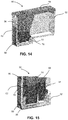
- FIG. 14 illustrates that the fluid funnels 56 are slightly larger than the chamber separator 58 in area 72, so that if the fluid chambers 64 are overfilled, the fluid flows over the top of the chamber separator 58 into the gap 68 where it can mix with other overflow fluids thus avoiding possible contamination between the fluids.
- the overflow area 70 is in an unused area of the cartridge body 52.
- FIG. 15 provides further illustration of the open fluid droplet ejection cartridge 50.
- the funnels 56 have a perimeter 74 adjacent to the chamber separator 58, that is slightly larger than the perimeter 76 of the chamber separator 58. Accordingly, if too much fluid is added to the fluid chambers 64, the flow will overflow into the gap 68.
- the perimeter 74 of the funnels 56 being smaller than the perimeter of the chamber separator 58 also promotes the release of air from the fluid as the fluid chambers 64 are filled.
- the difference in size of the perimeters of the funnels 56 and chamber separator 58 may be tailored to the viscosity and surface tension of the fluid being disposed into the fluid chambers 64.
- FIGs. 16-19 illustrate alternative openings in the cover of the open fluid droplet ejection cartridge 50.
- the openings 80 are disposed in the cover 54 in a two-dimensional array.
- the cover 82 contains parallel rectangular openings 84 that are each larger than the openings 80 in cover 54.
- the funnels 56 pending from cover 54 are substantially smaller than the funnels 86 pending from cover 82.
- Both embodiments provide cover designs with relatively large, deep fluid funnels 56 and 86 that may be effective to reduce errors when manually filling the open fluid droplet ejection cartridges 50 and 90 with a pipette.
- the open fluid droplet ejection cartridge 90 includes a cartridge body 92 and a cover 94. However, unlike the open fluid droplet ejection cartridge 50, the open fluid droplet ejection cartridge 90 includes four openings 96 in the cover 94. Accordingly, there are four fluid funnels 98 pending from the cover 94. Likewise, the chamber separator 100 disposed in the cartridge body 92 is designed for channeling four fluids to fluid vias in the semiconductor substrate 102. As before, a flexible circuit 104 provides electrical connection to the semiconductor substrate 102 for activating ejection devices adjacent to the vias on the semiconductor substrate 102.
- FIGs. 22-24 illustrate other aspects of the open fluid droplet ejection cartridge 90.
- a common chamber wall 106 is provided to separate the fluid chambers 108 from one another.
- FIG. 23 shows how the funnels 98 direct fluid into the fluid chambers 108.
- FIG. 24 illustrates the orientation of the chamber separator 100 in the cartridge body 92. Accordingly, the second embodiment provides an open-fluid droplet ejection cartridge 90 that can be used for ejecting up to four different fluids onto a substrate using the digital dispense system 10.
- cover and open fluid droplet ejection cartridge embodiments described above provide cover designs with relatively large openings 80, 84, and 96, in combination with large deep funnels 56, 86, and 98 that may be effective to reduce errors when manually filling the open fluid droplet ejection cartridges 50 and 90 with a pipette.
- the digital dispense system 10 may be used to deposit fluid into microwell plates 38 ( FIG. 6 ). Filling of microwell plates for experimentation can be a time consuming manual task. It is desirable to be able to deposit fluid into multiple wells 42 at the same time to decrease the time required to prepare the microwell plate 38.
- Conventional digital dispense systems exist, however the conventional systems have dispense heads arranged in a linear fashion along a single axis. The dispense head chips containing fluid ejectors are placed individually on such dispense heads.
- the present disclosure provides an improved fluid dispense system 10 by combining multiple fluid vias on a single semiconductor substrate 102 where the fluid vias are disposed in a two-dimensional matrix.
- Such two-dimensional matrix enables the time to fill wells 42 in the microwell plate 38 to be significantly decreased.
- the two-dimensional matrix may also improve registration between the fluid vias and the microwell plate 38 since the fluid vias are formed through photolithography techniques rather than mechanical placing individual ejection heads onto a semiconductor substrate.
- Various two-dimensional matrices of fluid vias may be used such as a two-by-two matrix, a four-by-two matrix, a four-by-four matrix, up to and including, but not limited to an eight-by-two matrix or a eight-by-four matrix of fluid vias.
- FIG. 25 is a plan view of the semiconductor substrate 102 containing four fluid vias 110A-110D on the semiconductor substrate 102 disposed in a two-by-two matrix. Ejection devices are disposed on both sides of the fluid vias in a conventional manner.
- the fluid vias 110A and 110B are spaced-apart a center-to-center distance D1 that corresponds to well 42 spacing on a microwell plate 38.
- the center-to-center distance D1 between fluid vias 110A and 110B ranges from about 2 to about 9 millimeters (mm). In some embodiments, the center-to-center distance D1 between fluid vias 110A and 110B is about 4.5 mm.
- the circles 112A-112D represent the bottom of the wells 42 in the microwell plate 38 and are about 2000 microns in diameter.
- a center-to-center distance D2 between fluid via 110A and fluid via 110C also ranges from about 2 to about 9 mm, such as about 4.5 mm.
- the distance D3 between fluid vias 110A and 110C or 110B and 110D ranges from about 1 to about 5 mm, such as about 25 about 3.2 mm.
- the substrate has a length L of about 7 to about 10 mm and a width W of about 5 to about 7 mm.
- fluid vias 114A-114D is shown in FIG. 26 .
- the fluid vias 114A-114B on the substrate 116 may be spaced apart a different distance D4 than the fluid vias 110A-110B.
- the fluid vias 114A and 114B are spaced apart a center-to-center distance D4 of about 2 to about 4 mm such as about 3.5 mm and fluid vias 114B and 114D are spaced apart a center-to-center distance D5 of about 3.5 to about 5 mm such as about 4.2 mm.
- the distance D6 between fluid vias 114A and 114C or 114B and 114D ranges from about 1 to about 2 mm such as about 1.7 mm.
- the fluid vias 110A-110D have a length L1 that is slightly less than the diameter 112A-112D of the bottom of the wells 42
- the fluid vias 114A-114D have a length L2 that is greater than the diameter 112A-112D of the bottom of the wells 42.
- FIGs. 27-29 illustrate addressing architectures for semiconductor substrates 102 or 116 containing a two-dimensional matrix of fluid vias, wherein P1-P8 represents the primitive addresses for sequencing the firing of ejection devices disposed on both sides of the fluid vias.
- the numbers along the perimeter of the fluid vias 114A and 114C represent the fluid ejectors in each ejection head.
- each fluid ejector dispenses 12 pL of fluid for example.
- fluid ejectors that dispense 48 pL of fluid are disposed along vias 118A and 188C as shown in FIG. 29 .
- 30 fluid ejectors are associate with each of the primitive addresses P1, P2, P7, and P8. Sharing a common addressing scheme between all fluid ejectors, regardless of the ejector size, reduces system integration complexity.
- the digital dispense system 10 can be used to deposit fluid into wells 40 of microwell plates 38, onto slides 36, onto circuit board substrates, or onto other substrates using the fluid ejection heads illustrated in FIGs. 25 and 26 disposed in a two-dimensional matrix of ejection heads.
- the two-dimension matrix of ejection heads provides improved registration accuracy between ejection heads, allowing for more precise filling of microwell plates, placement of droplets on a glass slide, or deposition of fluids on a circuit board substrate.
- a common digital addressing architecture multiple ejector fluid volumes can be digitally supported in the same dispense system as described above with reference to FIGs. 27 and 28 .
- the digital dispense system 10 described above can include one or more open fluid droplet ejection cartridges 50 or 90, or in an alternative embodiment, a digital dispense system 120 ( FIG. 30 ) may include both open fluid droplet ejection cartridges 122 and pre-filled fluid droplet ejection cartridges 124.
- the pre-filled cartridge 124 is also referred to as a closed fluid droplet ejection cartridge.
- the open fluid droplet ejection cartridges 122 allow the user to add a small amount of fluid into the cartridge 122 at the time of use.
- the open fluid droplet ejection cartridge may be referred to as a pipette cartridge and may be used in biological analysis fields such as hematology.
- each fluid droplet ejection cartridge may be configured to dispense a single fluid, or two different fluids.
Landscapes
- Chemical & Material Sciences (AREA)
- Health & Medical Sciences (AREA)
- Immunology (AREA)
- Pathology (AREA)
- Analytical Chemistry (AREA)
- Biochemistry (AREA)
- General Health & Medical Sciences (AREA)
- General Physics & Mathematics (AREA)
- Physics & Mathematics (AREA)
- Life Sciences & Earth Sciences (AREA)
- Clinical Laboratory Science (AREA)
- Chemical Kinetics & Catalysis (AREA)
- Coating Apparatus (AREA)
- Automatic Analysis And Handling Materials Therefor (AREA)
- Feeding, Discharge, Calcimining, Fusing, And Gas-Generation Devices (AREA)
- Sampling And Sample Adjustment (AREA)
Applications Claiming Priority (2)
| Application Number | Priority Date | Filing Date | Title |
|---|---|---|---|
| US201962788290P | 2019-01-04 | 2019-01-04 | |
| US16/724,982 US11768215B2 (en) | 2019-01-04 | 2019-12-23 | Digital dispense system cartridge |
Publications (2)
| Publication Number | Publication Date |
|---|---|
| EP3677921A1 true EP3677921A1 (fr) | 2020-07-08 |
| EP3677921B1 EP3677921B1 (fr) | 2023-02-22 |
Family
ID=69055712
Family Applications (1)
| Application Number | Title | Priority Date | Filing Date |
|---|---|---|---|
| EP19219773.9A Active EP3677921B1 (fr) | 2019-01-04 | 2019-12-27 | Une cartouche pour système de dosage numérique |
Country Status (4)
| Country | Link |
|---|---|
| US (1) | US11768215B2 (fr) |
| EP (1) | EP3677921B1 (fr) |
| JP (1) | JP7338464B2 (fr) |
| CN (1) | CN111413513B (fr) |
Cited By (2)
| Publication number | Priority date | Publication date | Assignee | Title |
|---|---|---|---|---|
| EP4032712A1 (fr) * | 2021-01-20 | 2022-07-27 | Funai Electric Co., Ltd. | Corps de réservoir de fluide remplissable par pipette et système numérique de distribution de fluide |
| EP4032711A1 (fr) * | 2021-01-20 | 2022-07-27 | Funai Electric Co., Ltd. | Corps de réservoir de fluide à moule unitaire et système numérique de distribution de fluide |
Families Citing this family (2)
| Publication number | Priority date | Publication date | Assignee | Title |
|---|---|---|---|---|
| US20220297424A1 (en) * | 2021-03-18 | 2022-09-22 | Funai Electric Co., Ltd. | Pipette-fillable cartridge fluid detection |
| WO2023127707A1 (fr) * | 2021-12-29 | 2023-07-06 | 株式会社Provigate | Procédé de mesure d'élément de composant d'hémocyte et d'élément de composant non-hémocyte dans une quantité infime de sang, dispositif et cartouche de pipette |
Citations (7)
| Publication number | Priority date | Publication date | Assignee | Title |
|---|---|---|---|---|
| US20030026737A1 (en) * | 2001-08-01 | 2003-02-06 | Takashi Inoue | Liquid ejection device and sample carrier preparation apparatus |
| EP1289660B1 (fr) * | 2000-06-15 | 2006-02-08 | Moussa Hoummady | Systeme de distribution parallele et selective de micro-gouttelettes a haut rendement |
| US20060153621A1 (en) * | 2002-09-27 | 2006-07-13 | Manning Howard J | Method and apparatus for substrate handling and printing |
| WO2009023459A1 (fr) * | 2007-08-13 | 2009-02-19 | Hewlett-Packard Development Company, L.P. | Système de distribution de fluide |
| EP2179025B1 (fr) * | 2007-07-13 | 2016-10-05 | Handylab, Inc. | Appareil intégré permettant d'effectuer l'extraction d'acides nucléiques et des tests diagnostiques sur de multiples échantillons biologiques |
| US20170043336A1 (en) * | 2013-03-11 | 2017-02-16 | Cue Inc. | Cartridges, kits, and methods for enhanced mixing for detection and quantification of analytes |
| EP3378562A1 (fr) * | 2017-03-24 | 2018-09-26 | Toshiba TEC Kabushiki Kaisha | Appareil de distribution de gouttelettes |
Family Cites Families (63)
| Publication number | Priority date | Publication date | Assignee | Title |
|---|---|---|---|---|
| US3568735A (en) * | 1968-06-26 | 1971-03-09 | Cooke Eng Co | Laboratory microtitration dispensing apparatus |
| JP2801409B2 (ja) * | 1989-12-26 | 1998-09-21 | キヤノン株式会社 | インクジェット装置及び記録系ユニットカートリッジ |
| US5958342A (en) | 1996-05-17 | 1999-09-28 | Incyte Pharmaceuticals, Inc. | Jet droplet device |
| ES2215241T3 (es) * | 1996-11-06 | 2004-10-01 | Sequenom, Inc. | Procedimiento de espectrometria de masa. |
| US5985214A (en) * | 1997-05-16 | 1999-11-16 | Aurora Biosciences Corporation | Systems and methods for rapidly identifying useful chemicals in liquid samples |
| US7661793B2 (en) * | 1997-07-15 | 2010-02-16 | Silverbrook Research Pty Ltd | Inkjet nozzle with individual ink feed channels etched from both sides of wafer |
| US6045759A (en) * | 1997-08-11 | 2000-04-04 | Ventana Medical Systems | Fluid dispenser |
| US7199809B1 (en) | 1998-10-19 | 2007-04-03 | Symyx Technologies, Inc. | Graphic design of combinatorial material libraries |
| US6627157B1 (en) | 1999-03-04 | 2003-09-30 | Ut-Battelle, Llc | Dual manifold system and method for fluid transfer |
| GB0018963D0 (en) * | 2000-08-03 | 2000-09-20 | Manning Howard J | Highly parallel fabrication of microarrays by ink jet printheads |
| US7135146B2 (en) | 2000-10-11 | 2006-11-14 | Innovadyne Technologies, Inc. | Universal non-contact dispense peripheral apparatus and method for a primary liquid handling device |
| JP3870020B2 (ja) | 2000-10-24 | 2007-01-17 | キヤノン株式会社 | インクジェットプリント装置および吐出データ作成方法 |
| US7024281B1 (en) * | 2000-12-11 | 2006-04-04 | Callper Life Sciences, Inc. | Software for the controlled sampling of arrayed materials |
| US6982063B2 (en) * | 2001-05-25 | 2006-01-03 | Matrix Technologies Corp | Automated pipetting system |
| US6864480B2 (en) * | 2001-12-19 | 2005-03-08 | Sau Lan Tang Staats | Interface members and holders for microfluidic array devices |
| JP2004074680A (ja) | 2002-08-21 | 2004-03-11 | Seiko Epson Corp | 液体噴射装置及び液体噴射ヘッド |
| US7568779B2 (en) | 2003-02-10 | 2009-08-04 | Canon Kabushiki Kaisha | Liquid applicator and liquid supply method to be used in liquid applicator |
| JP3695661B2 (ja) | 2003-10-02 | 2005-09-14 | セイコーエプソン株式会社 | 記録装置 |
| JP3950972B2 (ja) | 2003-11-14 | 2007-08-01 | 国立大学法人名古屋大学 | 生物試料の生物発光測定装置 |
| WO2005085775A1 (fr) | 2004-02-06 | 2005-09-15 | Seyonic S.A. | Dispositif de verification de pipette et pipette |
| US7534395B2 (en) | 2004-04-27 | 2009-05-19 | Beckman Coulter, Inc. | Hysteresis compensation system |
| US7267431B2 (en) * | 2004-06-30 | 2007-09-11 | Lexmark International, Inc. | Multi-fluid ejection device |
| WO2006014460A2 (fr) * | 2004-07-06 | 2006-02-09 | University Of Utah Research Foundation | Dispositif de depot de taches et procede de depot de taches a haute concentration, sur des jeux ordonnes de micro-echantillons et d'autres dispositifs a l'echelle microscopique |
| ATE485888T1 (de) * | 2004-08-26 | 2010-11-15 | Life Technologies Corp | Elektrobenetzende abgabevorrichtungen und dazugehörige verfahren |
| US7178904B2 (en) * | 2004-11-11 | 2007-02-20 | Lexmark International, Inc. | Ultra-low energy micro-fluid ejection device |
| JP2006145224A (ja) | 2004-11-16 | 2006-06-08 | Canon Inc | プローブ担体製造用の液体吐出装置及び製造装置 |
| CN100374301C (zh) | 2004-12-31 | 2008-03-12 | 财团法人工业技术研究院 | 打印数据转换方法及其装置 |
| EP1882189A2 (fr) | 2005-04-20 | 2008-01-30 | Fluidigm Corporation | Moteur d'analyse et base de donnees permettant de manipuler des parametres destines a des systemes fluidiques sur une puce |
| WO2007053692A1 (fr) | 2005-11-01 | 2007-05-10 | Symyx Technologies, Inc. | Distribution de liquides pour experimentation a fort rendement |
| CN101316652A (zh) | 2005-11-29 | 2008-12-03 | 皇家飞利浦电子股份有限公司 | 通过向基板上释放多种物质而制造生物检定基板的喷墨装置和方法 |
| JP2008151594A (ja) | 2006-12-15 | 2008-07-03 | Anritsu Sanki System Co Ltd | 分析装置 |
| US8959448B2 (en) | 2007-04-17 | 2015-02-17 | Emd Millipore Corporation | Graphical user interface for analysis and comparison of location-specific multiparameter data sets |
| US7909424B2 (en) | 2007-07-31 | 2011-03-22 | Hewlett-Packard Development Company, L.P. | Method and system for dispensing liquid |
| CN102316988B (zh) | 2007-09-29 | 2014-02-19 | Ei频谱有限责任公司 | 仪表化移液器吸头 |
| US8222048B2 (en) | 2007-11-05 | 2012-07-17 | Abbott Laboratories | Automated analyzer for clinical laboratory |
| EP2613155B1 (fr) | 2008-04-24 | 2014-04-30 | Tecan Trading AG | Pipetage direct dans des postes de traitement de liquide commandés par ordinateur |
| US9132629B2 (en) * | 2008-10-15 | 2015-09-15 | Hewlett-Packard Development Company, L.P. | Method of detecting drops |
| US8201913B2 (en) | 2009-04-20 | 2012-06-19 | Hewlett-Packard Development Company, L.P. | Drop detector |
| US8715574B2 (en) * | 2009-06-19 | 2014-05-06 | Abbott Laboratories | System for managing inventory of bulk liquids |
| JP4831215B2 (ja) | 2009-07-06 | 2011-12-07 | ブラザー工業株式会社 | 画像データ処理装置及び液体吐出装置 |
| JP5189664B2 (ja) | 2011-03-07 | 2013-04-24 | 富士フイルム株式会社 | 画像処理装置及び方法、並びに画像形成装置 |
| JP5866905B2 (ja) | 2011-09-16 | 2016-02-24 | ブラザー工業株式会社 | 印刷実行部に印刷を実行させるための制御装置 |
| CN105163857B (zh) * | 2012-09-18 | 2017-11-07 | 珠海丽珠圣美医疗诊断技术有限公司 | 流体储存器 |
| US9086394B2 (en) | 2012-10-24 | 2015-07-21 | Accel Biotech, Inc. | Multi-function dispense head |
| JP6272895B2 (ja) * | 2012-12-03 | 2018-01-31 | ザ セクレタリー オブ ステイト フォー エンバイロンメント,フード アンド ルーラル アフェアーズ | デバイスおよび装置 |
| DK2938998T3 (en) * | 2012-12-26 | 2017-08-28 | Ventana Med Syst Inc | SAMPLE TREATMENT SYSTEMS AND METHODS FOR REAGENT PREPARATION |
| EP2938994B1 (fr) * | 2012-12-26 | 2018-08-29 | Ventana Medical Systems, Inc. | Systèmes de traitement d'échantillon et procédés d'alignement de lames porte-objets |
| CN105073434B (zh) | 2012-12-27 | 2017-12-26 | 科迪华公司 | 用于打印油墨体积控制以在精确公差内沉积流体的方法和系统 |
| CN104884260B (zh) | 2013-01-08 | 2017-07-04 | 惠普发展公司,有限责任合伙企业 | 具有可变半径的内圆角的存储器 |
| AU2014305889B2 (en) * | 2013-08-08 | 2017-06-29 | Illumina, Inc. | Fluidic system for reagent delivery to a flow cell |
| JP6171949B2 (ja) | 2014-01-24 | 2017-08-02 | ブラザー工業株式会社 | 液体吐出ヘッド |
| JP6436351B2 (ja) * | 2015-03-27 | 2018-12-12 | ブラザー工業株式会社 | インクジェット記録装置用タンクユニット、インクジェット記録装置及び揮発性有機化合物の吸着方法 |
| TW201641310A (zh) * | 2015-03-30 | 2016-12-01 | 精工愛普生股份有限公司 | 液體供給裝置及印刷裝置 |
| JP6344861B2 (ja) * | 2015-06-15 | 2018-06-20 | 富士フイルム株式会社 | 液体吐出装置及び液体吐出ヘッドの保湿装置 |
| CN105082772A (zh) * | 2015-07-10 | 2015-11-25 | 深圳泓数科技有限公司 | 喷墨打印机供墨装置及喷墨打印机系统 |
| SG11201803655SA (en) * | 2015-11-04 | 2018-05-30 | Nitto Denko Corp | Apparatus and system for biofluid sample dispensing and/or assay |
| CN116046500A (zh) | 2016-04-28 | 2023-05-02 | 希森美康株式会社 | 样本涂抹装置 |
| EP3257676B1 (fr) * | 2016-06-15 | 2020-03-25 | Funai Electric Co., Ltd. | Dispositif de distribution de fluide ayant des fonctions pour réduire des zones de stagnation |
| EP3272537B1 (fr) * | 2016-07-21 | 2020-03-25 | Funai Electric Co., Ltd. | Dispositif de distribution de capsule |
| CN106199024A (zh) * | 2016-08-17 | 2016-12-07 | 江苏英诺华医疗技术有限公司 | 全自动生化分析仪及生化检测系统 |
| IES86926B2 (en) | 2016-09-19 | 2018-09-19 | Project Man Limited | An autonomous sampling system |
| US10639916B2 (en) | 2017-03-21 | 2020-05-05 | Ricoh Company, Ltd. | Conveyance device, conveyance system, and head unit position adjusting method |
| WO2019236053A1 (fr) | 2018-06-04 | 2019-12-12 | Hewlett-Packard Development Company, L.P. | Pas de sous-ensembles d'éjection pour une correspondance avec un espacement de nanopuits |
-
2019
- 2019-12-23 US US16/724,982 patent/US11768215B2/en active Active
- 2019-12-27 JP JP2019238065A patent/JP7338464B2/ja active Active
- 2019-12-27 EP EP19219773.9A patent/EP3677921B1/fr active Active
-
2020
- 2020-01-02 CN CN202010002552.1A patent/CN111413513B/zh active Active
Patent Citations (7)
| Publication number | Priority date | Publication date | Assignee | Title |
|---|---|---|---|---|
| EP1289660B1 (fr) * | 2000-06-15 | 2006-02-08 | Moussa Hoummady | Systeme de distribution parallele et selective de micro-gouttelettes a haut rendement |
| US20030026737A1 (en) * | 2001-08-01 | 2003-02-06 | Takashi Inoue | Liquid ejection device and sample carrier preparation apparatus |
| US20060153621A1 (en) * | 2002-09-27 | 2006-07-13 | Manning Howard J | Method and apparatus for substrate handling and printing |
| EP2179025B1 (fr) * | 2007-07-13 | 2016-10-05 | Handylab, Inc. | Appareil intégré permettant d'effectuer l'extraction d'acides nucléiques et des tests diagnostiques sur de multiples échantillons biologiques |
| WO2009023459A1 (fr) * | 2007-08-13 | 2009-02-19 | Hewlett-Packard Development Company, L.P. | Système de distribution de fluide |
| US20170043336A1 (en) * | 2013-03-11 | 2017-02-16 | Cue Inc. | Cartridges, kits, and methods for enhanced mixing for detection and quantification of analytes |
| EP3378562A1 (fr) * | 2017-03-24 | 2018-09-26 | Toshiba TEC Kabushiki Kaisha | Appareil de distribution de gouttelettes |
Cited By (2)
| Publication number | Priority date | Publication date | Assignee | Title |
|---|---|---|---|---|
| EP4032712A1 (fr) * | 2021-01-20 | 2022-07-27 | Funai Electric Co., Ltd. | Corps de réservoir de fluide remplissable par pipette et système numérique de distribution de fluide |
| EP4032711A1 (fr) * | 2021-01-20 | 2022-07-27 | Funai Electric Co., Ltd. | Corps de réservoir de fluide à moule unitaire et système numérique de distribution de fluide |
Also Published As
| Publication number | Publication date |
|---|---|
| JP7338464B2 (ja) | 2023-09-05 |
| US11768215B2 (en) | 2023-09-26 |
| US20200217868A1 (en) | 2020-07-09 |
| JP2020126043A (ja) | 2020-08-20 |
| EP3677921B1 (fr) | 2023-02-22 |
| CN111413513A (zh) | 2020-07-14 |
| CN111413513B (zh) | 2024-01-09 |
Similar Documents
| Publication | Publication Date | Title |
|---|---|---|
| EP3677921B1 (fr) | Une cartouche pour système de dosage numérique | |
| US7135146B2 (en) | Universal non-contact dispense peripheral apparatus and method for a primary liquid handling device | |
| US10724988B2 (en) | Digital microfluidics system with swappable PCB's | |
| US11933704B2 (en) | Digital dispense system | |
| EP1206321B1 (fr) | Bande souple pour pipette et son procede d'utilisation | |
| US20210165007A1 (en) | Ejection subassembly pitches to match nanowell spacing | |
| JP2022111988A (ja) | 一体型成型流体リザーバ本体と電子流体分注システム | |
| US11639056B2 (en) | Fluidic ejection controllers with selectively removable ejection boards | |
| JP3389352B2 (ja) | 液体分注装置 | |
| EP3677917B1 (fr) | Système de distribution numérique et méthode de distribution | |
| US11577250B2 (en) | Pipette-fillable cartridge | |
| CA2459730C (fr) | Module secondaire de distribution de liquide pour systeme de manipulation de liquide | |
| KR102227970B1 (ko) | 미세 액적 생성 장치 | |
| US20200326317A1 (en) | Fluidic ejection systems with titration plate form factors | |
| WO2003023410A1 (fr) | Module secondaire de distribution de liquide pour systeme de manipulation de liquide | |
| EP3703950B1 (fr) | Dispositifs d'alignement |
Legal Events
| Date | Code | Title | Description |
|---|---|---|---|
| PUAI | Public reference made under article 153(3) epc to a published international application that has entered the european phase |
Free format text: ORIGINAL CODE: 0009012 |
|
| STAA | Information on the status of an ep patent application or granted ep patent |
Free format text: STATUS: THE APPLICATION HAS BEEN PUBLISHED |
|
| AK | Designated contracting states |
Kind code of ref document: A1 Designated state(s): AL AT BE BG CH CY CZ DE DK EE ES FI FR GB GR HR HU IE IS IT LI LT LU LV MC MK MT NL NO PL PT RO RS SE SI SK SM TR |
|
| AX | Request for extension of the european patent |
Extension state: BA ME |
|
| STAA | Information on the status of an ep patent application or granted ep patent |
Free format text: STATUS: REQUEST FOR EXAMINATION WAS MADE |
|
| 17P | Request for examination filed |
Effective date: 20201222 |
|
| RBV | Designated contracting states (corrected) |
Designated state(s): AL AT BE BG CH CY CZ DE DK EE ES FI FR GB GR HR HU IE IS IT LI LT LU LV MC MK MT NL NO PL PT RO RS SE SI SK SM TR |
|
| REG | Reference to a national code |
Ref country code: DE Ref legal event code: R079 Ref document number: 602019025499 Country of ref document: DE Free format text: PREVIOUS MAIN CLASS: G01N0035100000 Ipc: B01L0003000000 |
|
| RIC1 | Information provided on ipc code assigned before grant |
Ipc: G01N 35/10 20060101ALI20221010BHEP Ipc: B01L 3/02 20060101ALI20221010BHEP Ipc: B01L 3/00 20060101AFI20221010BHEP |
|
| GRAP | Despatch of communication of intention to grant a patent |
Free format text: ORIGINAL CODE: EPIDOSNIGR1 |
|
| STAA | Information on the status of an ep patent application or granted ep patent |
Free format text: STATUS: GRANT OF PATENT IS INTENDED |
|
| INTG | Intention to grant announced |
Effective date: 20221129 |
|
| GRAS | Grant fee paid |
Free format text: ORIGINAL CODE: EPIDOSNIGR3 |
|
| GRAA | (expected) grant |
Free format text: ORIGINAL CODE: 0009210 |
|
| STAA | Information on the status of an ep patent application or granted ep patent |
Free format text: STATUS: THE PATENT HAS BEEN GRANTED |
|
| AK | Designated contracting states |
Kind code of ref document: B1 Designated state(s): AL AT BE BG CH CY CZ DE DK EE ES FI FR GB GR HR HU IE IS IT LI LT LU LV MC MK MT NL NO PL PT RO RS SE SI SK SM TR |
|
| REG | Reference to a national code |
Ref country code: GB Ref legal event code: FG4D |
|
| REG | Reference to a national code |
Ref country code: CH Ref legal event code: EP |
|
| REG | Reference to a national code |
Ref country code: DE Ref legal event code: R096 Ref document number: 602019025499 Country of ref document: DE |
|
| REG | Reference to a national code |
Ref country code: AT Ref legal event code: REF Ref document number: 1549160 Country of ref document: AT Kind code of ref document: T Effective date: 20230315 Ref country code: IE Ref legal event code: FG4D |
|
| REG | Reference to a national code |
Ref country code: LT Ref legal event code: MG9D |
|
| REG | Reference to a national code |
Ref country code: NL Ref legal event code: MP Effective date: 20230222 |
|
| REG | Reference to a national code |
Ref country code: AT Ref legal event code: MK05 Ref document number: 1549160 Country of ref document: AT Kind code of ref document: T Effective date: 20230222 |
|
| PG25 | Lapsed in a contracting state [announced via postgrant information from national office to epo] |
Ref country code: RS Free format text: LAPSE BECAUSE OF FAILURE TO SUBMIT A TRANSLATION OF THE DESCRIPTION OR TO PAY THE FEE WITHIN THE PRESCRIBED TIME-LIMIT Effective date: 20230222 Ref country code: PT Free format text: LAPSE BECAUSE OF FAILURE TO SUBMIT A TRANSLATION OF THE DESCRIPTION OR TO PAY THE FEE WITHIN THE PRESCRIBED TIME-LIMIT Effective date: 20230622 Ref country code: NO Free format text: LAPSE BECAUSE OF FAILURE TO SUBMIT A TRANSLATION OF THE DESCRIPTION OR TO PAY THE FEE WITHIN THE PRESCRIBED TIME-LIMIT Effective date: 20230522 Ref country code: NL Free format text: LAPSE BECAUSE OF FAILURE TO SUBMIT A TRANSLATION OF THE DESCRIPTION OR TO PAY THE FEE WITHIN THE PRESCRIBED TIME-LIMIT Effective date: 20230222 Ref country code: LV Free format text: LAPSE BECAUSE OF FAILURE TO SUBMIT A TRANSLATION OF THE DESCRIPTION OR TO PAY THE FEE WITHIN THE PRESCRIBED TIME-LIMIT Effective date: 20230222 Ref country code: LT Free format text: LAPSE BECAUSE OF FAILURE TO SUBMIT A TRANSLATION OF THE DESCRIPTION OR TO PAY THE FEE WITHIN THE PRESCRIBED TIME-LIMIT Effective date: 20230222 Ref country code: HR Free format text: LAPSE BECAUSE OF FAILURE TO SUBMIT A TRANSLATION OF THE DESCRIPTION OR TO PAY THE FEE WITHIN THE PRESCRIBED TIME-LIMIT Effective date: 20230222 Ref country code: ES Free format text: LAPSE BECAUSE OF FAILURE TO SUBMIT A TRANSLATION OF THE DESCRIPTION OR TO PAY THE FEE WITHIN THE PRESCRIBED TIME-LIMIT Effective date: 20230222 Ref country code: AT Free format text: LAPSE BECAUSE OF FAILURE TO SUBMIT A TRANSLATION OF THE DESCRIPTION OR TO PAY THE FEE WITHIN THE PRESCRIBED TIME-LIMIT Effective date: 20230222 |
|
| PG25 | Lapsed in a contracting state [announced via postgrant information from national office to epo] |
Ref country code: SE Free format text: LAPSE BECAUSE OF FAILURE TO SUBMIT A TRANSLATION OF THE DESCRIPTION OR TO PAY THE FEE WITHIN THE PRESCRIBED TIME-LIMIT Effective date: 20230222 Ref country code: PL Free format text: LAPSE BECAUSE OF FAILURE TO SUBMIT A TRANSLATION OF THE DESCRIPTION OR TO PAY THE FEE WITHIN THE PRESCRIBED TIME-LIMIT Effective date: 20230222 Ref country code: IS Free format text: LAPSE BECAUSE OF FAILURE TO SUBMIT A TRANSLATION OF THE DESCRIPTION OR TO PAY THE FEE WITHIN THE PRESCRIBED TIME-LIMIT Effective date: 20230622 Ref country code: GR Free format text: LAPSE BECAUSE OF FAILURE TO SUBMIT A TRANSLATION OF THE DESCRIPTION OR TO PAY THE FEE WITHIN THE PRESCRIBED TIME-LIMIT Effective date: 20230523 Ref country code: FI Free format text: LAPSE BECAUSE OF FAILURE TO SUBMIT A TRANSLATION OF THE DESCRIPTION OR TO PAY THE FEE WITHIN THE PRESCRIBED TIME-LIMIT Effective date: 20230222 |
|
| PG25 | Lapsed in a contracting state [announced via postgrant information from national office to epo] |
Ref country code: SM Free format text: LAPSE BECAUSE OF FAILURE TO SUBMIT A TRANSLATION OF THE DESCRIPTION OR TO PAY THE FEE WITHIN THE PRESCRIBED TIME-LIMIT Effective date: 20230222 Ref country code: RO Free format text: LAPSE BECAUSE OF FAILURE TO SUBMIT A TRANSLATION OF THE DESCRIPTION OR TO PAY THE FEE WITHIN THE PRESCRIBED TIME-LIMIT Effective date: 20230222 Ref country code: EE Free format text: LAPSE BECAUSE OF FAILURE TO SUBMIT A TRANSLATION OF THE DESCRIPTION OR TO PAY THE FEE WITHIN THE PRESCRIBED TIME-LIMIT Effective date: 20230222 Ref country code: DK Free format text: LAPSE BECAUSE OF FAILURE TO SUBMIT A TRANSLATION OF THE DESCRIPTION OR TO PAY THE FEE WITHIN THE PRESCRIBED TIME-LIMIT Effective date: 20230222 Ref country code: CZ Free format text: LAPSE BECAUSE OF FAILURE TO SUBMIT A TRANSLATION OF THE DESCRIPTION OR TO PAY THE FEE WITHIN THE PRESCRIBED TIME-LIMIT Effective date: 20230222 |
|
| REG | Reference to a national code |
Ref country code: DE Ref legal event code: R097 Ref document number: 602019025499 Country of ref document: DE |
|
| PG25 | Lapsed in a contracting state [announced via postgrant information from national office to epo] |
Ref country code: SK Free format text: LAPSE BECAUSE OF FAILURE TO SUBMIT A TRANSLATION OF THE DESCRIPTION OR TO PAY THE FEE WITHIN THE PRESCRIBED TIME-LIMIT Effective date: 20230222 |
|
| PLBE | No opposition filed within time limit |
Free format text: ORIGINAL CODE: 0009261 |
|
| STAA | Information on the status of an ep patent application or granted ep patent |
Free format text: STATUS: NO OPPOSITION FILED WITHIN TIME LIMIT |
|
| 26N | No opposition filed |
Effective date: 20231123 |
|
| PG25 | Lapsed in a contracting state [announced via postgrant information from national office to epo] |
Ref country code: SI Free format text: LAPSE BECAUSE OF FAILURE TO SUBMIT A TRANSLATION OF THE DESCRIPTION OR TO PAY THE FEE WITHIN THE PRESCRIBED TIME-LIMIT Effective date: 20230222 |
|
| PGFP | Annual fee paid to national office [announced via postgrant information from national office to epo] |
Ref country code: DE Payment date: 20231031 Year of fee payment: 5 |