EP3675331B1 - Motorstator - Google Patents
Motorstator Download PDFInfo
- Publication number
- EP3675331B1 EP3675331B1 EP19216651.0A EP19216651A EP3675331B1 EP 3675331 B1 EP3675331 B1 EP 3675331B1 EP 19216651 A EP19216651 A EP 19216651A EP 3675331 B1 EP3675331 B1 EP 3675331B1
- Authority
- EP
- European Patent Office
- Prior art keywords
- hairpin
- leg
- wire
- layer
- slots
- Prior art date
- Legal status (The legal status is an assumption and is not a legal conclusion. Google has not performed a legal analysis and makes no representation as to the accuracy of the status listed.)
- Active
Links
Images


Classifications
-
- H—ELECTRICITY
- H02—GENERATION; CONVERSION OR DISTRIBUTION OF ELECTRIC POWER
- H02K—DYNAMO-ELECTRIC MACHINES
- H02K3/00—Details of windings
- H02K3/42—Means for preventing or reducing eddy-current losses in the winding heads, e.g. by shielding
-
- H—ELECTRICITY
- H02—GENERATION; CONVERSION OR DISTRIBUTION OF ELECTRIC POWER
- H02K—DYNAMO-ELECTRIC MACHINES
- H02K3/00—Details of windings
- H02K3/04—Windings characterised by the conductor shape, form or construction, e.g. with bar conductors
- H02K3/12—Windings characterised by the conductor shape, form or construction, e.g. with bar conductors arranged in slots
-
- H—ELECTRICITY
- H02—GENERATION; CONVERSION OR DISTRIBUTION OF ELECTRIC POWER
- H02K—DYNAMO-ELECTRIC MACHINES
- H02K1/00—Details of the magnetic circuit
- H02K1/06—Details of the magnetic circuit characterised by the shape, form or construction
- H02K1/12—Stationary parts of the magnetic circuit
- H02K1/16—Stator cores with slots for windings
-
- H—ELECTRICITY
- H02—GENERATION; CONVERSION OR DISTRIBUTION OF ELECTRIC POWER
- H02K—DYNAMO-ELECTRIC MACHINES
- H02K3/00—Details of windings
- H02K3/04—Windings characterised by the conductor shape, form or construction, e.g. with bar conductors
- H02K3/28—Layout of windings or of connections between windings
-
- H—ELECTRICITY
- H02—GENERATION; CONVERSION OR DISTRIBUTION OF ELECTRIC POWER
- H02K—DYNAMO-ELECTRIC MACHINES
- H02K3/00—Details of windings
- H02K3/04—Windings characterised by the conductor shape, form or construction, e.g. with bar conductors
- H02K3/12—Windings characterised by the conductor shape, form or construction, e.g. with bar conductors arranged in slots
- H02K3/14—Windings characterised by the conductor shape, form or construction, e.g. with bar conductors arranged in slots with transposed conductors, e.g. twisted conductors
Definitions
- the present disclosure relates to a motor stator, and more particularly to a motor stator including hairpin wires.
- the wires wound around receiving slots of an iron core typically require a sufficient cross-sectional area to conduct large currents due to low voltage applications or high power requirements.
- a single copper wire with a large cross section has the advantage of a higher slot occupying ratio, but an AC loss of the large cross-sectional copper wire may rise rapidly along with the motor's increasing speed due to the skin effect and the proximity effect.
- EP 1 381 140 A2 and US 2018/294686 A1 relate to motor stators having a core with a plurality of slots that comprise a number of layers, and pluralities of wires inserted in the layers.
- a motor stator comprises a core and a plurality of first, second and third hairpin wires.
- the core comprises a plurality of slots, an insertion side and an extension side opposite to the insertion side, wherein each slot comprises a first layer, a second layer, a third layer, a fourth layer, a fifth layer and a sixth layer, configured from outer to inner in a radial direction of the core.
- Each first hairpin wire comprises a first hairpin first leg and a first hairpin second leg, wherein each first hairpin first leg is inserted into the third layer of the slots from the insertion side and protruded out of the slots from the extension side and bent in a first direction, wherein each first hairpin second leg is inserted into the sixth layer of the slots from the insertion side and protruded out of the slots from the extension side and bent in a second direction.
- Each second hairpin wire comprises a second hairpin first leg and a second hairpin second leg, wherein each second hairpin first leg is inserted into the fourth layer of the slots from the insertion side and protruded out of the slots from the extension side and bent in a third direction, wherein each second hairpin second leg is inserted into the fifth layer of the slots from the insertion side and protruded out of the slots from the extension side and bent in a fourth direction.
- Each third hairpin wire comprises a third hairpin first leg and a third hairpin second leg, wherein each third hairpin first leg is inserted into the first layer of the slots and each third hairpin second leg is inserted into the second layer of the slots.
- Each first hairpin first leg is connected with the immediately-adjacent first hairpin second leg, second hairpin first leg and second hairpin second leg to form a first winding set.
- a motor stator comprises a core and a plurality of first, second and third hairpin wires.
- the core comprises a plurality of slots, an insertion side and an extension side opposite to the insertion side, wherein each slot comprises a first layer, a second layer, a third layer, a fourth layer, a fifth layer and a sixth layer, configured from outer to inner in a radial direction of the core.
- Each first hairpin wire comprises a first hairpin first leg and a first hairpin second leg, wherein each first hairpin first leg is inserted into the third layer of the slots, wherein each first hairpin second leg is inserted into the sixth layer of the slots.
- Each second hairpin wire comprises a second hairpin first leg and a second hairpin second leg, wherein each second hairpin first leg is inserted into the fourth layer of the slots, wherein each second hairpin second leg is inserted into the fifth layer of the slots.
- Each third hairpin wire comprises a third hairpin first leg and a third hairpin second leg, wherein each third hairpin first leg is inserted into the first layer of the slots and each third hairpin second leg is inserted into the second layer of the slots.
- a plurality of immediately-adjacent hairpin legs are connected such that the first hairpin first leg the first hairpin second leg, the second hairpin first leg and the second hairpin second leg are connected to form a first winding set, and the third hairpin first leg and the third hairpin second leg are connected to form a second winding set.
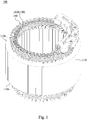
- a motor stator 100 includes an iron core 110 and a plurality of hairpin wires (e.g., hairpin wires 120, 130, 140) inserted thereon.
- the iron core 110 has a plurality of slots 112 to be inserted by the hairpin wires that are configured to be connected.
- the number of slots 112 can be 48, 60 or 120, but not being limited thereto.
- the number of slots can be configured according to the design requirements of the motor stator. Within the limits of the design specifications, configuring an iron core with more slots may result in a denser wire configuration, which makes the gap between the wires closer.
- the iron core 110 has an insertion side 110a and an extension side 110b opposite to the insertion side. That is, the insertion side 110a and the extension side 110b are at opposite sides of the iron core 110.
- Each slot 112 is configured, with respect to the radial direction 114 of the iron core 110 (e.g., from an outer side 110d to an inner side 110c of the iron core), with a first layer 112a, a second layer 112b, a third layer 112c, a fourth layer 112d, a fifth layer 112e, and a sixth layer 112f.
- the radial direction 114 of the iron core 110 is substantially perpendicular to a circumferential direction 115 of the iron core 110.
- two legs of the hairpin wires 140 are respectively inserted into the first layer 112a and the second layer 112b of the slots 112.
- the hairpin wires (120, 130) are inserted into the third to sixth layers (112c to 112f) of the slots 112.
- the immediately-adjacent legs of the hairpin wires 140 are protruded out of the first and second layers 112a, 112b of the slots 112 and connected to form a winding.
- the immediately adjacent legs of the hairpin wires (120, 130) are protruded out of the third to sixth layers (112c to 112f) and connected to form another winding. That is, the windings formed by the plurality of hairpin wires (120, 130) are connected to each other, which will be described later in detail.
- each slot can accommodate six layers of wires as an example, but the number of wire accommodating layers per slot is not limited thereto.
- the hairpin wires include the hairpin wire 120 imposed on the outside of the hairpin wire 130, and are inserted into the iron core 110.
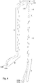
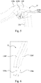
- Each of the hairpin wires 120 or 130 includes a U-turn section U and two legs, and the two legs extend from the sides of the U-turn section U.
- Each leg further includes an inclined section S, a longitudinal section V, and a foot section T.
- the hairpin wire 120 has opposite surface 120a and surface 120b.
- the hairpin wire 130 has opposite surface 130a and surface 130b.
- the hairpin wire 120 is imposed on an outer surface of the hairpin wire 130, i.e., the surface 120b of the hairpin wire 120 partially or completely contacts the surface 130a of the hairpin wire 130.
- each hairpin wire 120, 130 has an insulation coating, for example, the hairpin wire 120 is coated with an insulation coating 120f, and the hairpin wire 130 is coated with an insulation coating 130f.
- the ends of the two legs of each hairpin wire are exposed from the insulation coating such that the two legs can be electrically connected to each other.
- the end 120e of the leg of the hairpin wire 120 is exposed from the insulation coating 120f
- the end 130e of the leg of the hairpin wire 130 is exposed from the insulation coating 130f, such that the ends (120e, 130e) can be welded to form an electrical connection.
- Each hairpin wire 120 or 130 may be coated with the insulation coating except for the ends of the two legs.
- the aforementioned surfaces 120a, 120b, 130a, 130b may be the surfaces of the insulation coating, and a contact between the surface 120b and the surface 130a is the contact between the surfaces of the insulation coating.
- a total length of the hairpin wire 120 is substantially greater than a total length of the hairpin wire 130, but not being limited thereto.
- both the hairpin wire 120 and its imposed hairpin wire 130 have a U-turn section U, and a bent angle of the hairpin wire 120 at the U-turn section U is different from that of the hairpin wire 130. Specifically, a turning angle ⁇ of the hairpin wires 120 at the U-turn section U is greater than a turning angle ⁇ of the hairpin wire 130 at the U-turn section U.
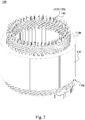
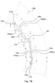
- Figs. 7A , 7B and 7C the third to sixth layers 112c-112f of the slots 112 of the iron core 110 are configured to be inserted by the hairpin wires 120, 130.
- the hairpin wires 120, 130 and slots 112 of the iron core 110 To more clearly illustrate the positional relationship of each of the hairpin wires 120, 130 and slots 112 of the iron core 110, only one of the hairpin wires 120, 130 is illustrated.
- Each hairpin wire 120 is imposed to an outer side of a corresponding hairpin wire 130.
- Each hairpin wire 120 has two legs 120c, 120d.
- the leg 120c of each hairpin wire 120 is inserted into the third layer 112c of the slots 112 from the insertion side 110a of the iron core 110, and protruded out of the third layer 112c of the slots 112 from the extension side 110b of the iron core 110, and bent in the direction 115a, and extended over a span distance D1.
- the other leg 120d of each hairpin wire 120 is inserted into the sixth layer 112f of the slots 112 from the insertion side 110a of the iron core 110, and protruded out of the sixth layer 112f of the slots 112 from the extension side 110b of the iron core 110, and bent in the direction 115b, and extended over a span distance D2.
- the span distance D1 is substantially the same as the span distance D2. Note that the for reference direction 115a and the direction 115b are opposite circumferential directions 115.
- Each hairpin wire 130 has two legs 130c, 130d.
- the leg 130c of each hairpin wire 130 is inserted into the fourth layer 112d of the slots 112 from the insertion side 110a of the iron core 110, and protruded out of the fourth layer 112d of the slots 112 from the extension side 110b of the iron core 110, and bent in the direction 115a, and extended over a span distance D1.
- the other leg 130d of each hairpin wire 130 is inserted into the fifth layer 112e of the slots 112 from the insertion side 110a of the iron core 110, and protruded out of the fifth layer 112e of the slots 112 from the extension side 110b of the iron core 110, and bent in the direction 115b, and extended over a span distance D2.
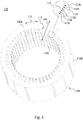
- the surface 120a(1) at the inclined section S of one leg 120c of each hairpin wire 120 faces towards the outer side 110d of the iron core
- the surface 120a(2) at the inclined section S of the other leg 120d faces towards the inner side 110c of the iron core.
- two surfaces 120a(1), 120a(2) at the inclined section S of a continuous surface on the two legs (120c, 120d) face towards two opposite directions in the radial direction 114 on the insertion side 110a, respectively.
- the surface 130b(1) at the inclined section S of one leg 130c of each hairpin wire 130 faces towards the inner side 110c of the iron core, and the surface 130b(2) at the inclined section S of the other leg 130d faces towards the outer side 110d of the iron core.
- two surfaces 130b(1), 130b(2) at the inclined section S of a continuous surface on two legs (130c, 130d) face towards two opposite directions in the radial direction 114 on the insertion side 110a, respectively.
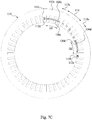
- each of the hairpin wires (120, 130) has its legs (120c, 130c) protruded from the third layer 112c and the fourth layer 112d of the slots 112 and connected to immediately adjacent legs (120d, 130d), i.e., legs of another hairpin wires (120, 130), that are protruded from the sixth layer 112f and the fifth layer 112e of the slots 112 at the ends (e.g., by welding) to form a first winding.
- the legs 120c, 130c, 120d, 130d
- the legs have their respective ends aligned to be immediately adjacent at some positions (for example, at position J1 or J2) such that all the hairpin wires 120, 130 are connected to form a winding (as shown in Fig. 2 ).
- the two legs (120c, 120d) of the hairpin wire 120 are inserted into the third layer 112c and the sixth layer 112f of the slots 112, and the two legs (130c, 130d) of the hairpin wire 130 are inserted into the fourth layer 112d and the fifth layer 112e of the slots 112.
- the direction T1 of the magnetic field eddy formed at the junction (e.g., the welded point) of the two legs (120c, 130c) is opposite to the direction T2 of the magnetic field eddy formed at the junction (e.g., the welded point) of the two legs (120d, 130d), thereby canceling the eddy current of the magnetic field and reducing the eddy current loss.
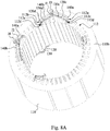
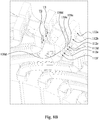
- a leg 140a of each hairpin wire 140 is protruded out of the first layer 112a of the slots 112, and is connected to an immediately-adjacent leg (i.e., a leg 140b of another hairpin wire 140) that is protruded out of the second layer 112b of the slots 112 (e.g., connected at position J3 or J4) to form a second winding.
- an immediately-adjacent leg i.e., a leg 140b of another hairpin wire 140
- the surface 120a of the hairpin wire 120 is farther from a top surface of the insertion side 110a of the iron core 110 than the surface 130a of the hairpin wire 130.
- a cross-sectional area C2 of each hairpin wire 120 is substantially equal to a cross-sectional area C3 of each hairpin wire 130.
- a cross-sectional area sum (C2+C3) of each hairpin wire 120 and each hairpin wire 130 is less than or substantially equal to a cross-sectional area C1 of each hairpin wire 140.
- the cross-sectional area C1 of each hairpin wire 140 is greater than the cross-sectional area C2 of each hairpin wire 120, or the cross-sectional area C1 of each hairpin wire 140 is greater than the cross-sectional area C3 of each hairpin wires 130.
- this disclosure does not limit the relationship between the cross-sectional areas of various wires.
- the motor stator structure includes an insulation sheet 170 between the first layer 112a and the second layer 112b of the slots. That is, the insulation sheet 170 is positioned between immediately-adjacent legs (140a, 140b) of the hairpin wires 140 protruding out of the extension side 110b of the iron core 110.
- the motor stator structure includes an insulation sheet 180 between the fourth layer 112d and the fifth layer 112e of the slots, that is, the insulation sheet 180 is located between the immediately adjacent legs (130c, 130d) of the hairpin wires 130 protruding out of the extension side 110b of the iron core 110.
- An insulation sheet may improve the insulation between adjacent wires by providing a physical barrier between the wires.
- the motor stator structure may not be provided with the aforementioned insulation sheet 170 or insulation sheet 180, or may be provided with both the insulation sheet 170 and the insulation sheet 180, or provided with either one of the insulation sheet 170 and the insulation sheet 180.
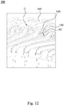
- Figs. 12 and 13 The manner by which the hairpin wires (120, 130, 140) of the motor stator 100 may be inserted into the slots of the iron core illustrated in Fig. 12 is previously described in reference to Figs. 1-11 .
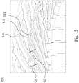
- the motor stator 101 illustrated in Fig. 13 is different from the motor stator 100 mainly in the manner by which the hairpin wires (121, 131) are inserted into the slots of the iron core, and the hairpin wires (121, 131) are also imposed on each other.
- One leg of each hairpin wire 121 is inserted into the third layer 112c of the slots 112 of the iron core, and the other leg is inserted into the fifth layer 112e of the slots 112 of the iron core.
- each hairpin wire 131 is inserted into the fourth layer 112d of the slots 112 of the iron core and the other leg is inserted into the sixth layer 112f of the slots 112 of the iron core.
- the hairpin wires 141 are similar to the hairpin wires 140 discussed in previously described embodiments, and their legs are respectively inserted into the first layer 112a and the second layer 112b of the slots 112. Similarly, the hairpin wires 141 are connected to each other to form a first winding, and the hairpin wires 121 and the hairpin wires 131 are connected to each other to form a second winding.
- the hairpin wires (121, 131) of the motor stator 101 are inserted into the slots of the iron core in a manner different from the hairpin wires (120, 130) of the previously described embodiments of the motor stator 100, and the hairpin wires (121, 131) at its U-turn section U has a more obtuse U-turn than the U-turn section U of the hairpin wires (120,130) of the previously described embodiments.
- the U-turn section U of the hairpin wires (120, 130) of the previously described embodiments having a sharper U-turn, provides a larger minimum wire spacing G1 of the hairpin wires (120, 130) than a minimum wire spacing G2 of the hairpin wires (121, 131). Accordingly, a larger wire spacing between the wires may improve overall insulation reliability of the motor stator 100.
- Fig. 14 which illustrates an impedance comparison diagram of two operating motor stators (100, 101). Attention is directed to the curve L1 showing a change in the impedance value of the motor stator 100 operating between frequencies of 400 Hz to 1200 Hz and the curve L2 showing a change in the impedance value of the motor stator 101 operating between frequencies of 400 Hz to 1200 Hz. Comparing the curves L1 and L2, it can be seen that the impedance value of the motor stator 100 at higher frequency is notably lower than the impedance value of the motor stator 101 at the comparable higher frequency. That is, it indicates that an operating loss of the motor stator 100 at higher frequency is lower than that of the motor stator 101.
- the hairpin wires connected at the extension side are configured to better offset magnetic field eddy current (as shown in Fig. 8B ) such that the equivalent impedance value can be more effectively reduced, thereby reducing an operation loss for the motor.
Landscapes
- Engineering & Computer Science (AREA)
- Power Engineering (AREA)
- Windings For Motors And Generators (AREA)
Claims (13)
- Motorstator (100), welcher Folgendes umfasst:einen Kern (110) mit einer Vielzahl von Schlitzen (112), einer Einfügungsseite (110a) und einer Erweiterungsseite (110b) gegenüber der Einfügungsseite (110a), wobei jeder Schlitz eine erste Schicht (112a), eine zweite Schicht (112b), eine dritte Schicht (112c), eine vierte Schicht (112d), eine fünfte Schicht (112e) und eine sechste Schicht (112f) umfasst, die von außen nach innen in eine radiale Richtung (114) des Kerns (110) konfiguriert sind;eine Vielzahl von ersten Haarnadeldrähten (120), wobei jeder erste Haarnadeldraht (120) einen ersten Schenkel der ersten Haarnadel (120c) und einen zweiten Schenkel der ersten Haarnadel (120d) umfasst, wobei jeder erste Schenkel der ersten Haarnadel (120c) in die dritte Schicht (112c) der Schlitze (112) von der Einfügungsseite (110a) eingefügt ist und aus den Schlitzen (112) von der Erweiterungsseite (110b) herausragt und in eine erste Richtung (115a) gebogen ist, wobei jeder zweite Schenkel der ersten Haarnadel (120d) in die sechste Schicht (112f) der Schlitze (112) von der Einfügungsseite (110a) eingefügt ist und aus den Schlitzen (112) von der Erweiterungsseite (110b) herausragt und in eine zweite Richtung (115b) gebogen ist;eine Vielzahl von zweiten Haarnadeldrähten (130), wobei jeder zweite Haarnadeldraht (130) einen ersten Schenkel der zweiten Haarnadel (130c) und einen zweiten Schenkel der zweiten Haarnadel (130d) umfasst, wobei jeder erste Schenkel der zweiten Haarnadel (130c) in die vierte Schicht (112d) der Schlitze (112) von der Einfügungsseite (110a) eingefügt ist und aus den Schlitzen (112) von der Erweiterungsseite (110b) herausragt und in eine dritte Richtung (115a) gebogen ist, wobei jeder zweite Schenkel der zweiten Haarnadel (130d) in die fünfte Schicht (112e) der Schlitze (112) von der Einfügungsseite (110a) eingefügt ist und aus den Schlitzen (112) von der Erweiterungsseite (110b) herausragt und in eine vierte Richtung (115b) gebogen ist; undeine Vielzahl von dritten Haarnadeldrähten (140), wobei jeder dritte Haarnadeldraht (140) einen ersten Schenkel der dritten Haarnadel (140a) und einen zweiten Schenkel der dritten Haarnadel (140b) umfasst, wobei jeder erste Schenkel der dritten Haarnadel (140a) in die erste Schicht (112a) der Schlitze (112) eingefügt ist und jeder zweite Schenkel der dritten Haarnadel (140b) in die zweite Schicht (112b) der Schlitze (112) eingefügt ist,gekennzeichnet durch:wobei jeder erste Schenkel der ersten Haarnadel (120c) mit dem unmittelbar angrenzenden zweiten Schenkel der ersten Haarnadel (120d), ersten Schenkel der zweiten Haarnadel (130c) und zweiten Schenkel der zweiten Haarnadel (130d) verbunden ist, um einen ersten Wicklungssatz zu bilden,wobei die erste Richtung (115a) und die dritte Richtung (115a) die gleiche Umfangsrichtung haben, die zweite Richtung (115b) und die vierte Richtung (115b) die gleiche Umfangsrichtung haben und die erste Richtung (115a) der zweiten Richtung (115b) entgegengesetzt ist.
- Motorstator nach Anspruch 1, wobei jeder erste Haarnadeldraht (120) einen ersten Haarnadelwendeabschnitt (U) umfasst und der erste Schenkel der ersten Haarnadel (120c) und der zweite Schenkel der ersten Haarnadel (120d) sich von dem ersten Haarnadelwendeabschnitt (U) aus erstrecken, wobei jeder zweite Haarnadeldraht (130) einen zweiten Haarnadelwendeabschnitt (U) umfasst und der erste Schenkel der zweiten Haarnadel (130c) und der zweite Schenkel der zweiten Haarnadel (130d) sich von dem zweiten Haarnadelwendeabschnitt (U) aus erstrecken, wobei der erste Haarnadelwendeabschnitt (U) und der zweite Haarnadelwendeabschnitt (U) sich an der Einfügungsseite (110a) des Kerns (110) befinden und wobei ein Drehwinkel (µ) des ersten Haarnadelwendeabschnitts (U) größer als ein Drehwinkel (θ) des zweiten Haarnadelwendeabschnitts (U) ist.
- Motorstator nach einem der Ansprüche 1-2, wobei jeder erste Haarnadeldraht (120) eine erste Oberfläche der ersten Haarnadel (120a) und eine zweite Oberfläche der ersten Haarnadel (120b) gegenüber der ersten Oberfläche der ersten Haarnadel (120a) umfasst und jeder zweite Haarnadeldraht (130) eine erste Oberfläche der zweiten Haarnadel (130a) und eine zweite Oberfläche der zweiten Haarnadel (130b) gegenüber der ersten Oberfläche der zweiten Haarnadel (130a) umfasst und wobei sich die zweite Oberfläche der ersten Haarnadel (120b) auf die erste Oberfläche der zweiten Haarnadel (130a) auflegt.
- Motorstator nach Anspruch 3, wobei jeder erste Haarnadeldraht (120) und jeder zweite Haarnadeldraht (130) einen Wendeabschnitt (U) an der Einfügungsseite (110a) des Kerns (110) umfasst und wobei an dem Wendeabschnitt (U) die erste Oberfläche der ersten Haarnadel (120a) weiter von einer Oberfläche der Einfügungsseite (110a) des Kerns (110) entfernt ist als die erste Oberfläche der zweiten Haarnadel (130a).
- Motorstator nach Anspruch 3 oder Anspruch 4, wobeijeder erste Haarnadeldraht (120) einen ersten geneigten Schenkelabschnitt (S) und einen zweiten geneigten Schenkelabschnitt (S) umfasst, die sich an der Einfügungsseite (110a) des Kerns (110) befinden, und wobei die erste Oberfläche der ersten Haarnadel (120a(1)) an dem ersten geneigten Schenkelabschnitt (S) zu einer Außenseite (110d) des Kerns (110) zeigt, und wobei die erste Oberfläche der ersten Haarnadel (120a(2)) an dem zweiten geneigten Schenkelabschnitt (S) zu einer Innenseite (110c) des Kerns (110) zeigt, undjeder zweite Haarnadeldraht (130) einen ersten geneigten Schenkelabschnitt (S) und einen zweiten geneigten Schenkelabschnitt (S) umfasst, die sich an der Einfügungsseite (110a) des Kerns (110) befinden, und wobei die zweite Oberfläche der zweiten Haarnadel (130b(1)) an dem ersten geneigten Schenkelabschnitt (S) zu einer Innenseite (110c) des Kerns (110) zeigt und die zweite Oberfläche der zweiten Haarnadel (130b(2)) an dem zweiten Schenkel der zweiten Haarnadel (130d) zu einer Außenseite (110d) des Kerns (110) zeigt.
- Motorstator nach einem der Ansprüche 1-5, wobei jeder erste, zweite, dritte Haarnadeldraht (120, 130, 140) eine Querschnittsfläche umfasst, und wobei die dritte Haarnadeldraht-Querschnittsfläche (C1) größer als die erste Haarnadeldraht-Querschnittsfläche (C2) oder die zweite Haarnadeldraht-Querschnittsfläche (C3) ist, und die erste Haarnadeldraht-Querschnittsfläche (C2) im Wesentlichen gleich der zweiten Haarnadeldraht-Querschnittsfläche (C3) ist.
- Motorstator nach einem der Ansprüche 1-6, welcher ferner Folgendes umfasst:eine Isolierfolie (170), die zwischen dem ersten Schenkel der dritten Haarnadel (140a) und dem zweiten Schenkel der dritten Haarnadel (140b) angeordnet ist, die an der Erweiterungsseite (110b) aus der ersten Schicht (112a) bzw. der zweiten Schicht (112b) der Schlitze (112) herausragen; und/odereine Isolierfolie (180), die zwischen dem ersten Schenkel der zweiten Haarnadel (130c) und dem zweiten Schenkel der zweiten Haarnadel (130d) angeordnet ist, die an der Erweiterungsseite (110b) aus der vierten Schicht (112d) bzw. der fünften Schicht (112e) der Schlitze (112) herausragen.
- Motorstator nach einem der Ansprüche 1-7, wobei der erste Schenkel der ersten Haarnadel (120c), der aus den Schlitzen (112) an der Erweiterungsseite (110b) herausragt und sich in die erste Richtung (115a) biegt, konfiguriert ist, um sich über eine erste Spannweitendistanz (D1) zu erstrecken; wobei der zweite Schenkel der ersten Haarnadel (120d), der aus den Schlitzen (112) an der Erweiterungsseite (110b) herausragt und sich in die zweite Richtung (115b) biegt, konfiguriert ist, um sich über eine zweite Spannweitendistanz (D2) zu erstrecken; und wobei die erste Spannweitendistanz (D1) im Wesentlichen gleich der zweiten Spannweitendistanz (D2) ist.
- Motorstator nach einem der Ansprüche 1-8, wobei jeder erste Haarnadeldraht (120) eine Gesamtlänge umfasst, die größer als eine Gesamtlänge jedes zweiten Haarnadeldrahts (130) ist.
- Motorstator nach Anspruch 1, wobei jeder erste Schenkel der dritten Haarnadel (140a) mit dem unmittelbar angrenzenden zweiten Schenkel der dritten Haarnadel (140b) verbunden ist, um einen zweiten Wicklungssatz zu bilden.
- Motorstator nach Anspruch 10, wobei jeder erste Haarnadeldraht (120) eine erste Oberfläche der ersten Haarnadel (120a) und eine zweite Oberfläche der ersten Haarnadel (120b) gegenüber der ersten Oberfläche der ersten Haarnadel (120a) umfasst, wobei jeder erste Haarnadeldraht (120) ferner einen ersten geneigten Schenkelabschnitt (S) und einen zweiten geneigten Schenkelabschnitt (S) umfasst, die sich an der Einfügungsseite (110a) des Kerns (110) befinden, und wobei die erste Oberfläche der ersten Haarnadel (120a(1), 120a(2)) an dem ersten geneigten Schenkelabschnitt (S) und der zweite geneigte Schenkelabschnitt (S) in entgegengesetzte Richtungen in die radiale Richtung (114) des Kerns (110) zeigen.
- Motorstator nach Anspruch 11, wobei jeder zweite Haarnadeldraht (130) eine erste Oberfläche der zweiten Haarnadel (130a) und eine zweite Oberfläche der zweiten Haarnadel (130b) gegenüber der ersten Oberfläche der zweiten Haarnadel (130a) umfasst, wobei jeder zweite Haarnadeldraht (130) ferner einen ersten geneigten Schenkelabschnitt (S) und einen zweiten geneigten Schenkelabschnitt (S) umfasst, die sich an der Einfügungsseite (110a) des Kerns (110) befinden, und wobei die erste Oberfläche der zweiten Haarnadel (130b(1), 130b(2)) an dem ersten geneigten Schenkelabschnitt der zweiten Haarnadel (S) und der zweite geneigte Schenkelabschnitt der zweiten Haarnadel (S) in entgegengesetzte Richtungen in die radiale Richtung (114) des Kerns (110) zeigen, und wobei die zweite Oberfläche der ersten Haarnadel (120b) in Kontakt mit der ersten Oberfläche der zweiten Haarnadel (130a) ist.
- Motorstator nach einem der Ansprüche 10-12, welcher ferner eine erste Isolierfolie (180) umfasst, die zwischen dem ersten Schenkel der zweiten Haarnadel (130c) und dem zweiten Schenkel der zweiten Haarnadel (130d) angeordnet ist, die an der Erweiterungsseite (110b) aus der vierten Schicht (112d) bzw. der fünften Schicht (112e) der Schlitze (112) herausragen, und/oder eine zweite Isolierfolie (170), die zwischen dem ersten Schenkel der dritten Haarnadel (140a) und dem zweiten Schenkel der dritten Haarnadel (140b) angeordnet ist, die an der Erweiterungsseite (110b) aus der ersten Schicht (112a) bzw. der zweiten Schicht (112b) der Schlitze (112) herausragen.
Applications Claiming Priority (2)
| Application Number | Priority Date | Filing Date | Title |
|---|---|---|---|
| US201862785704P | 2018-12-28 | 2018-12-28 | |
| CN201910504040.2A CN111384806B (zh) | 2018-12-28 | 2019-06-12 | 马达定子 |
Publications (2)
| Publication Number | Publication Date |
|---|---|
| EP3675331A1 EP3675331A1 (de) | 2020-07-01 |
| EP3675331B1 true EP3675331B1 (de) | 2021-09-29 |
Family
ID=68917683
Family Applications (1)
| Application Number | Title | Priority Date | Filing Date |
|---|---|---|---|
| EP19216651.0A Active EP3675331B1 (de) | 2018-12-28 | 2019-12-16 | Motorstator |
Country Status (2)
| Country | Link |
|---|---|
| US (1) | US11381129B2 (de) |
| EP (1) | EP3675331B1 (de) |
Families Citing this family (6)
| Publication number | Priority date | Publication date | Assignee | Title |
|---|---|---|---|---|
| KR102618459B1 (ko) * | 2019-01-07 | 2023-12-27 | 엘지마그나 이파워트레인 주식회사 | 회전전기기계의 스테이터 |
| US11605989B2 (en) * | 2019-11-27 | 2023-03-14 | Borgwarner Inc. | Stator winding with alternating winding pitches |
| KR102696292B1 (ko) * | 2020-01-08 | 2024-08-20 | 엘지마그나 이파워트레인 주식회사 | 회전 전기 기기의 스테이터 |
| FR3121297A1 (fr) * | 2021-03-29 | 2022-09-30 | Nidec Psa Emotors | Conducteur électrique pour stator de machine électrique tournante et procédé de fabrication |
| EP4300781A1 (de) * | 2022-06-30 | 2024-01-03 | Valeo eAutomotive Germany GmbH | Stator für eine elektrische maschine, elektrische maschine, elektrischer antrieb für ein fahrzeug und fahrzeug |
| DE102024206277A1 (de) * | 2024-07-03 | 2026-01-08 | Volkswagen Aktiengesellschaft | Stator mit unterschiedlich schräg geführten Wicklungsstäben, Elektromaschine und Kraftfahrzeug |
Family Cites Families (18)
| Publication number | Priority date | Publication date | Assignee | Title |
|---|---|---|---|---|
| US6181043B1 (en) * | 1997-12-10 | 2001-01-30 | Denso Corporation | Alternator for vehicle |
| JP4108257B2 (ja) * | 2000-07-24 | 2008-06-25 | 三菱電機株式会社 | 交流発電機 |
| US6894417B2 (en) | 2002-05-15 | 2005-05-17 | Remy Inc. | Multi-set rectangular copper hairpin windings for electric machines |
| DE10326095A1 (de) | 2002-06-12 | 2004-04-15 | Denso Corp., Kariya | Spule aus sequentiell verbundenen Segmenten für eine rotierende elektrische Maschine |
| JP4186872B2 (ja) * | 2004-05-24 | 2008-11-26 | 株式会社デンソー | 4層型セグメント順次接合ステータコイル及びその製造方法 |
| CN102812620B (zh) | 2010-03-11 | 2015-09-30 | 株式会社丰田自动织机 | 旋转电机的定子、定子的制造方法、以及定子的线圈的制造方法 |
| US8487498B2 (en) | 2010-07-30 | 2013-07-16 | Hamilton Sundstrand Corporation | Multiple conductor winding in stator |
| US20140035404A1 (en) * | 2012-08-02 | 2014-02-06 | Colin Hamer | Angled weld end turns for coolant access |
| KR101365469B1 (ko) * | 2012-09-20 | 2014-02-25 | 현대모비스 주식회사 | 헤어핀 접속기구 및 이를 구비한 헤어핀 권선모터 |
| WO2015180811A1 (de) * | 2014-05-28 | 2015-12-03 | Sew-Eurodrive Gmbh & Co. Kg | Elektrische maschine und verfahren zum herstellen einer elektrischen maschine |
| JP6591198B2 (ja) | 2015-05-22 | 2019-10-16 | 日立オートモティブシステムズ株式会社 | 回転電機の固定子 |
| JP2017093097A (ja) * | 2015-11-06 | 2017-05-25 | 株式会社デンソー | 回転電機 |
| TWI622249B (zh) | 2016-11-25 | 2018-04-21 | 台達電子工業股份有限公司 | 定子 |
| DE102016123067A1 (de) | 2016-11-30 | 2018-05-30 | Dr. Ing. H.C. F. Porsche Aktiengesellschaft | Stabwicklungsanordnung eines Stators oder eines Rotors einer elektrischen Maschine |
| DE102016123068A1 (de) | 2016-11-30 | 2018-05-30 | Dr. Ing. H.C. F. Porsche Aktiengesellschaft | Rotierende elektrische Maschine und besonders angepasstes Verfahren zum Herstellen einer solchen |
| CN106787335A (zh) * | 2016-12-16 | 2017-05-31 | 华中科技大学 | 一种混合导体绕组结构及具有该结构的电机及其应用 |
| CN207304180U (zh) | 2017-08-31 | 2018-05-01 | 长城汽车股份有限公司 | 一种电机定子及电机 |
| CN109038878B (zh) * | 2018-07-17 | 2020-12-18 | 法法汽车(中国)有限公司 | 三相电机定子及电动汽车驱动电机 |
-
2019
- 2019-12-03 US US16/701,173 patent/US11381129B2/en active Active
- 2019-12-16 EP EP19216651.0A patent/EP3675331B1/de active Active
Also Published As
| Publication number | Publication date |
|---|---|
| US20200212750A1 (en) | 2020-07-02 |
| US11381129B2 (en) | 2022-07-05 |
| EP3675331A1 (de) | 2020-07-01 |
Similar Documents
| Publication | Publication Date | Title |
|---|---|---|
| EP3675331B1 (de) | Motorstator | |
| JP7175876B2 (ja) | モータステータ | |
| US10186921B2 (en) | Stator of rotary electric machine having slots coils and connection coils | |
| US8716910B2 (en) | Stator winding connection arrangement | |
| JP5565381B2 (ja) | 回転電機の固定子 | |
| CN111030331B (zh) | 马达定子及其形成方法 | |
| US11165301B2 (en) | Interior bus bar for electric machine winding | |
| US7262538B2 (en) | Concentrated winding stator coil for an electric rotary machine | |
| JP6638008B2 (ja) | 回転電機のステータ | |
| US9431863B2 (en) | Insulation component for an electric machine and method of assembly | |
| JP2001211587A (ja) | 回転電機の固定子 | |
| US20240128824A1 (en) | Dynamo-Electric Machine | |
| US11996744B2 (en) | Vehicle motor stator structure | |
| JP2018117466A (ja) | 回転電機のステータ | |
| US12500467B2 (en) | Surface insulating material of a dynamoelectrical machine | |
| US20150372551A1 (en) | Structure of stator | |
| JP2023145164A (ja) | ステータ | |
| CN110311494A (zh) | 旋转电机用定子及电动车辆 | |
| JP2020171168A (ja) | 回転電機の固定子 | |
| JP6855993B2 (ja) | 回転電機のステータ | |
| JP2009268190A (ja) | 回転電機 | |
| JP2002354732A (ja) | 回転電機 |
Legal Events
| Date | Code | Title | Description |
|---|---|---|---|
| PUAI | Public reference made under article 153(3) epc to a published international application that has entered the european phase |
Free format text: ORIGINAL CODE: 0009012 |
|
| STAA | Information on the status of an ep patent application or granted ep patent |
Free format text: STATUS: THE APPLICATION HAS BEEN PUBLISHED |
|
| AK | Designated contracting states |
Kind code of ref document: A1 Designated state(s): AL AT BE BG CH CY CZ DE DK EE ES FI FR GB GR HR HU IE IS IT LI LT LU LV MC MK MT NL NO PL PT RO RS SE SI SK SM TR |
|
| AX | Request for extension of the european patent |
Extension state: BA ME |
|
| STAA | Information on the status of an ep patent application or granted ep patent |
Free format text: STATUS: REQUEST FOR EXAMINATION WAS MADE |
|
| 17P | Request for examination filed |
Effective date: 20210107 |
|
| RBV | Designated contracting states (corrected) |
Designated state(s): AL AT BE BG CH CY CZ DE DK EE ES FI FR GB GR HR HU IE IS IT LI LT LU LV MC MK MT NL NO PL PT RO RS SE SI SK SM TR |
|
| GRAP | Despatch of communication of intention to grant a patent |
Free format text: ORIGINAL CODE: EPIDOSNIGR1 |
|
| STAA | Information on the status of an ep patent application or granted ep patent |
Free format text: STATUS: GRANT OF PATENT IS INTENDED |
|
| RIC1 | Information provided on ipc code assigned before grant |
Ipc: H02K 3/12 20060101AFI20210326BHEP Ipc: H02K 3/28 20060101ALI20210326BHEP Ipc: H02K 15/06 20060101ALN20210326BHEP Ipc: H02K 3/14 20060101ALN20210326BHEP Ipc: H02K 3/42 20060101ALN20210326BHEP |
|
| INTG | Intention to grant announced |
Effective date: 20210420 |
|
| GRAS | Grant fee paid |
Free format text: ORIGINAL CODE: EPIDOSNIGR3 |
|
| GRAA | (expected) grant |
Free format text: ORIGINAL CODE: 0009210 |
|
| STAA | Information on the status of an ep patent application or granted ep patent |
Free format text: STATUS: THE PATENT HAS BEEN GRANTED |
|
| AK | Designated contracting states |
Kind code of ref document: B1 Designated state(s): AL AT BE BG CH CY CZ DE DK EE ES FI FR GB GR HR HU IE IS IT LI LT LU LV MC MK MT NL NO PL PT RO RS SE SI SK SM TR |
|
| REG | Reference to a national code |
Ref country code: GB Ref legal event code: FG4D |
|
| REG | Reference to a national code |
Ref country code: CH Ref legal event code: EP Ref country code: AT Ref legal event code: REF Ref document number: 1435076 Country of ref document: AT Kind code of ref document: T Effective date: 20211015 |
|
| REG | Reference to a national code |
Ref country code: DE Ref legal event code: R096 Ref document number: 602019008015 Country of ref document: DE |
|
| REG | Reference to a national code |
Ref country code: IE Ref legal event code: FG4D |
|
| REG | Reference to a national code |
Ref country code: LT Ref legal event code: MG9D |
|
| PG25 | Lapsed in a contracting state [announced via postgrant information from national office to epo] |
Ref country code: SE Free format text: LAPSE BECAUSE OF FAILURE TO SUBMIT A TRANSLATION OF THE DESCRIPTION OR TO PAY THE FEE WITHIN THE PRESCRIBED TIME-LIMIT Effective date: 20210929 Ref country code: RS Free format text: LAPSE BECAUSE OF FAILURE TO SUBMIT A TRANSLATION OF THE DESCRIPTION OR TO PAY THE FEE WITHIN THE PRESCRIBED TIME-LIMIT Effective date: 20210929 Ref country code: BG Free format text: LAPSE BECAUSE OF FAILURE TO SUBMIT A TRANSLATION OF THE DESCRIPTION OR TO PAY THE FEE WITHIN THE PRESCRIBED TIME-LIMIT Effective date: 20211229 Ref country code: LT Free format text: LAPSE BECAUSE OF FAILURE TO SUBMIT A TRANSLATION OF THE DESCRIPTION OR TO PAY THE FEE WITHIN THE PRESCRIBED TIME-LIMIT Effective date: 20210929 Ref country code: HR Free format text: LAPSE BECAUSE OF FAILURE TO SUBMIT A TRANSLATION OF THE DESCRIPTION OR TO PAY THE FEE WITHIN THE PRESCRIBED TIME-LIMIT Effective date: 20210929 Ref country code: FI Free format text: LAPSE BECAUSE OF FAILURE TO SUBMIT A TRANSLATION OF THE DESCRIPTION OR TO PAY THE FEE WITHIN THE PRESCRIBED TIME-LIMIT Effective date: 20210929 Ref country code: NO Free format text: LAPSE BECAUSE OF FAILURE TO SUBMIT A TRANSLATION OF THE DESCRIPTION OR TO PAY THE FEE WITHIN THE PRESCRIBED TIME-LIMIT Effective date: 20211229 |
|
| REG | Reference to a national code |
Ref country code: NL Ref legal event code: MP Effective date: 20210929 |
|
| REG | Reference to a national code |
Ref country code: AT Ref legal event code: MK05 Ref document number: 1435076 Country of ref document: AT Kind code of ref document: T Effective date: 20210929 |
|
| PG25 | Lapsed in a contracting state [announced via postgrant information from national office to epo] |
Ref country code: LV Free format text: LAPSE BECAUSE OF FAILURE TO SUBMIT A TRANSLATION OF THE DESCRIPTION OR TO PAY THE FEE WITHIN THE PRESCRIBED TIME-LIMIT Effective date: 20210929 Ref country code: GR Free format text: LAPSE BECAUSE OF FAILURE TO SUBMIT A TRANSLATION OF THE DESCRIPTION OR TO PAY THE FEE WITHIN THE PRESCRIBED TIME-LIMIT Effective date: 20211230 |
|
| PG25 | Lapsed in a contracting state [announced via postgrant information from national office to epo] |
Ref country code: AT Free format text: LAPSE BECAUSE OF FAILURE TO SUBMIT A TRANSLATION OF THE DESCRIPTION OR TO PAY THE FEE WITHIN THE PRESCRIBED TIME-LIMIT Effective date: 20210929 |
|
| PG25 | Lapsed in a contracting state [announced via postgrant information from national office to epo] |
Ref country code: IS Free format text: LAPSE BECAUSE OF FAILURE TO SUBMIT A TRANSLATION OF THE DESCRIPTION OR TO PAY THE FEE WITHIN THE PRESCRIBED TIME-LIMIT Effective date: 20220129 Ref country code: SK Free format text: LAPSE BECAUSE OF FAILURE TO SUBMIT A TRANSLATION OF THE DESCRIPTION OR TO PAY THE FEE WITHIN THE PRESCRIBED TIME-LIMIT Effective date: 20210929 Ref country code: RO Free format text: LAPSE BECAUSE OF FAILURE TO SUBMIT A TRANSLATION OF THE DESCRIPTION OR TO PAY THE FEE WITHIN THE PRESCRIBED TIME-LIMIT Effective date: 20210929 Ref country code: PT Free format text: LAPSE BECAUSE OF FAILURE TO SUBMIT A TRANSLATION OF THE DESCRIPTION OR TO PAY THE FEE WITHIN THE PRESCRIBED TIME-LIMIT Effective date: 20220131 Ref country code: PL Free format text: LAPSE BECAUSE OF FAILURE TO SUBMIT A TRANSLATION OF THE DESCRIPTION OR TO PAY THE FEE WITHIN THE PRESCRIBED TIME-LIMIT Effective date: 20210929 Ref country code: NL Free format text: LAPSE BECAUSE OF FAILURE TO SUBMIT A TRANSLATION OF THE DESCRIPTION OR TO PAY THE FEE WITHIN THE PRESCRIBED TIME-LIMIT Effective date: 20210929 Ref country code: ES Free format text: LAPSE BECAUSE OF FAILURE TO SUBMIT A TRANSLATION OF THE DESCRIPTION OR TO PAY THE FEE WITHIN THE PRESCRIBED TIME-LIMIT Effective date: 20210929 Ref country code: EE Free format text: LAPSE BECAUSE OF FAILURE TO SUBMIT A TRANSLATION OF THE DESCRIPTION OR TO PAY THE FEE WITHIN THE PRESCRIBED TIME-LIMIT Effective date: 20210929 Ref country code: CZ Free format text: LAPSE BECAUSE OF FAILURE TO SUBMIT A TRANSLATION OF THE DESCRIPTION OR TO PAY THE FEE WITHIN THE PRESCRIBED TIME-LIMIT Effective date: 20210929 Ref country code: AL Free format text: LAPSE BECAUSE OF FAILURE TO SUBMIT A TRANSLATION OF THE DESCRIPTION OR TO PAY THE FEE WITHIN THE PRESCRIBED TIME-LIMIT Effective date: 20210929 |
|
| REG | Reference to a national code |
Ref country code: DE Ref legal event code: R097 Ref document number: 602019008015 Country of ref document: DE |
|
| PG25 | Lapsed in a contracting state [announced via postgrant information from national office to epo] |
Ref country code: MC Free format text: LAPSE BECAUSE OF FAILURE TO SUBMIT A TRANSLATION OF THE DESCRIPTION OR TO PAY THE FEE WITHIN THE PRESCRIBED TIME-LIMIT Effective date: 20210929 Ref country code: DK Free format text: LAPSE BECAUSE OF FAILURE TO SUBMIT A TRANSLATION OF THE DESCRIPTION OR TO PAY THE FEE WITHIN THE PRESCRIBED TIME-LIMIT Effective date: 20210929 |
|
| PLBE | No opposition filed within time limit |
Free format text: ORIGINAL CODE: 0009261 |
|
| STAA | Information on the status of an ep patent application or granted ep patent |
Free format text: STATUS: NO OPPOSITION FILED WITHIN TIME LIMIT |
|
| 26N | No opposition filed |
Effective date: 20220630 |
|
| REG | Reference to a national code |
Ref country code: BE Ref legal event code: MM Effective date: 20211231 |
|
| PG25 | Lapsed in a contracting state [announced via postgrant information from national office to epo] |
Ref country code: LU Free format text: LAPSE BECAUSE OF NON-PAYMENT OF DUE FEES Effective date: 20211216 Ref country code: IE Free format text: LAPSE BECAUSE OF NON-PAYMENT OF DUE FEES Effective date: 20211216 |
|
| PG25 | Lapsed in a contracting state [announced via postgrant information from national office to epo] |
Ref country code: SI Free format text: LAPSE BECAUSE OF FAILURE TO SUBMIT A TRANSLATION OF THE DESCRIPTION OR TO PAY THE FEE WITHIN THE PRESCRIBED TIME-LIMIT Effective date: 20210929 Ref country code: BE Free format text: LAPSE BECAUSE OF NON-PAYMENT OF DUE FEES Effective date: 20211231 |
|
| PG25 | Lapsed in a contracting state [announced via postgrant information from national office to epo] |
Ref country code: IT Free format text: LAPSE BECAUSE OF FAILURE TO SUBMIT A TRANSLATION OF THE DESCRIPTION OR TO PAY THE FEE WITHIN THE PRESCRIBED TIME-LIMIT Effective date: 20210929 |
|
| PG25 | Lapsed in a contracting state [announced via postgrant information from national office to epo] |
Ref country code: CY Free format text: LAPSE BECAUSE OF FAILURE TO SUBMIT A TRANSLATION OF THE DESCRIPTION OR TO PAY THE FEE WITHIN THE PRESCRIBED TIME-LIMIT Effective date: 20210929 |
|
| PG25 | Lapsed in a contracting state [announced via postgrant information from national office to epo] |
Ref country code: SM Free format text: LAPSE BECAUSE OF FAILURE TO SUBMIT A TRANSLATION OF THE DESCRIPTION OR TO PAY THE FEE WITHIN THE PRESCRIBED TIME-LIMIT Effective date: 20210929 Ref country code: HU Free format text: LAPSE BECAUSE OF FAILURE TO SUBMIT A TRANSLATION OF THE DESCRIPTION OR TO PAY THE FEE WITHIN THE PRESCRIBED TIME-LIMIT; INVALID AB INITIO Effective date: 20191216 |
|
| REG | Reference to a national code |
Ref country code: CH Ref legal event code: PL |
|
| PG25 | Lapsed in a contracting state [announced via postgrant information from national office to epo] |
Ref country code: LI Free format text: LAPSE BECAUSE OF NON-PAYMENT OF DUE FEES Effective date: 20221231 Ref country code: CH Free format text: LAPSE BECAUSE OF NON-PAYMENT OF DUE FEES Effective date: 20221231 |
|
| PG25 | Lapsed in a contracting state [announced via postgrant information from national office to epo] |
Ref country code: MK Free format text: LAPSE BECAUSE OF FAILURE TO SUBMIT A TRANSLATION OF THE DESCRIPTION OR TO PAY THE FEE WITHIN THE PRESCRIBED TIME-LIMIT Effective date: 20210929 |
|
| PG25 | Lapsed in a contracting state [announced via postgrant information from national office to epo] |
Ref country code: TR Free format text: LAPSE BECAUSE OF FAILURE TO SUBMIT A TRANSLATION OF THE DESCRIPTION OR TO PAY THE FEE WITHIN THE PRESCRIBED TIME-LIMIT Effective date: 20210929 |
|
| GBPC | Gb: european patent ceased through non-payment of renewal fee |
Effective date: 20231216 |
|
| PG25 | Lapsed in a contracting state [announced via postgrant information from national office to epo] |
Ref country code: MT Free format text: LAPSE BECAUSE OF FAILURE TO SUBMIT A TRANSLATION OF THE DESCRIPTION OR TO PAY THE FEE WITHIN THE PRESCRIBED TIME-LIMIT Effective date: 20210929 |
|
| PG25 | Lapsed in a contracting state [announced via postgrant information from national office to epo] |
Ref country code: GB Free format text: LAPSE BECAUSE OF NON-PAYMENT OF DUE FEES Effective date: 20231216 |
|
| PG25 | Lapsed in a contracting state [announced via postgrant information from national office to epo] |
Ref country code: GB Free format text: LAPSE BECAUSE OF NON-PAYMENT OF DUE FEES Effective date: 20231216 |
|
| PGFP | Annual fee paid to national office [announced via postgrant information from national office to epo] |
Ref country code: DE Payment date: 20251022 Year of fee payment: 7 |
|
| PGFP | Annual fee paid to national office [announced via postgrant information from national office to epo] |
Ref country code: FR Payment date: 20251023 Year of fee payment: 7 |