EP3674733B1 - Vorrichtung und verfahren zur schätzung des zustands einer sekundärbatterie - Google Patents
Vorrichtung und verfahren zur schätzung des zustands einer sekundärbatterie Download PDFInfo
- Publication number
- EP3674733B1 EP3674733B1 EP19751476.3A EP19751476A EP3674733B1 EP 3674733 B1 EP3674733 B1 EP 3674733B1 EP 19751476 A EP19751476 A EP 19751476A EP 3674733 B1 EP3674733 B1 EP 3674733B1
- Authority
- EP
- European Patent Office
- Prior art keywords
- secondary battery
- charge time
- charge
- time
- voltage
- Prior art date
- Legal status (The legal status is an assumption and is not a legal conclusion. Google has not performed a legal analysis and makes no representation as to the accuracy of the status listed.)
- Active
Links
Images


Classifications
-
- G—PHYSICS
- G01—MEASURING; TESTING
- G01R—MEASURING ELECTRIC VARIABLES; MEASURING MAGNETIC VARIABLES
- G01R31/00—Arrangements for testing electric properties; Arrangements for locating electric faults; Arrangements for electrical testing characterised by what is being tested not provided for elsewhere
- G01R31/36—Arrangements for testing, measuring or monitoring the electrical condition of accumulators or electric batteries, e.g. capacity or state of charge [SoC]
- G01R31/392—Determining battery ageing or deterioration, e.g. state of health
-
- G—PHYSICS
- G01—MEASURING; TESTING
- G01R—MEASURING ELECTRIC VARIABLES; MEASURING MAGNETIC VARIABLES
- G01R31/00—Arrangements for testing electric properties; Arrangements for locating electric faults; Arrangements for electrical testing characterised by what is being tested not provided for elsewhere
- G01R31/36—Arrangements for testing, measuring or monitoring the electrical condition of accumulators or electric batteries, e.g. capacity or state of charge [SoC]
- G01R31/3644—Constructional arrangements
- G01R31/3646—Constructional arrangements for indicating electrical conditions or variables, e.g. visual or audible indicators
-
- G—PHYSICS
- G01—MEASURING; TESTING
- G01R—MEASURING ELECTRIC VARIABLES; MEASURING MAGNETIC VARIABLES
- G01R31/00—Arrangements for testing electric properties; Arrangements for locating electric faults; Arrangements for electrical testing characterised by what is being tested not provided for elsewhere
- G01R31/36—Arrangements for testing, measuring or monitoring the electrical condition of accumulators or electric batteries, e.g. capacity or state of charge [SoC]
- G01R31/3644—Constructional arrangements
- G01R31/3648—Constructional arrangements comprising digital calculation means, e.g. for performing an algorithm
-
- G—PHYSICS
- G01—MEASURING; TESTING
- G01R—MEASURING ELECTRIC VARIABLES; MEASURING MAGNETIC VARIABLES
- G01R31/00—Arrangements for testing electric properties; Arrangements for locating electric faults; Arrangements for electrical testing characterised by what is being tested not provided for elsewhere
- G01R31/36—Arrangements for testing, measuring or monitoring the electrical condition of accumulators or electric batteries, e.g. capacity or state of charge [SoC]
- G01R31/382—Arrangements for monitoring battery or accumulator variables, e.g. SoC
- G01R31/3835—Arrangements for monitoring battery or accumulator variables, e.g. SoC involving only voltage measurements
-
- H—ELECTRICITY
- H01—ELECTRIC ELEMENTS
- H01M—PROCESSES OR MEANS, e.g. BATTERIES, FOR THE DIRECT CONVERSION OF CHEMICAL ENERGY INTO ELECTRICAL ENERGY
- H01M10/00—Secondary cells; Manufacture thereof
- H01M10/42—Methods or arrangements for servicing or maintenance of secondary cells or secondary half-cells
- H01M10/44—Methods for charging or discharging
-
- H—ELECTRICITY
- H01—ELECTRIC ELEMENTS
- H01M—PROCESSES OR MEANS, e.g. BATTERIES, FOR THE DIRECT CONVERSION OF CHEMICAL ENERGY INTO ELECTRICAL ENERGY
- H01M10/00—Secondary cells; Manufacture thereof
- H01M10/42—Methods or arrangements for servicing or maintenance of secondary cells or secondary half-cells
- H01M10/46—Accumulators structurally combined with charging apparatus
-
- H—ELECTRICITY
- H01—ELECTRIC ELEMENTS
- H01M—PROCESSES OR MEANS, e.g. BATTERIES, FOR THE DIRECT CONVERSION OF CHEMICAL ENERGY INTO ELECTRICAL ENERGY
- H01M10/00—Secondary cells; Manufacture thereof
- H01M10/42—Methods or arrangements for servicing or maintenance of secondary cells or secondary half-cells
- H01M10/48—Accumulators combined with arrangements for measuring, testing or indicating the condition of cells, e.g. the level or density of the electrolyte
-
- H—ELECTRICITY
- H02—GENERATION; CONVERSION OR DISTRIBUTION OF ELECTRIC POWER
- H02J—ELECTRIC POWER NETWORKS; CIRCUIT ARRANGEMENTS OR SYSTEMS FOR SUPPLYING OR DISTRIBUTING ELECTRIC POWER; SYSTEMS FOR STORING ELECTRIC ENERGY
- H02J7/00—Circuit arrangements for charging or discharging batteries or for supplying loads from batteries
- H02J7/80—Circuit arrangements for charging or discharging batteries or for supplying loads from batteries including monitoring or indicating arrangements
-
- Y—GENERAL TAGGING OF NEW TECHNOLOGICAL DEVELOPMENTS; GENERAL TAGGING OF CROSS-SECTIONAL TECHNOLOGIES SPANNING OVER SEVERAL SECTIONS OF THE IPC; TECHNICAL SUBJECTS COVERED BY FORMER USPC CROSS-REFERENCE ART COLLECTIONS [XRACs] AND DIGESTS
- Y02—TECHNOLOGIES OR APPLICATIONS FOR MITIGATION OR ADAPTATION AGAINST CLIMATE CHANGE
- Y02E—REDUCTION OF GREENHOUSE GAS [GHG] EMISSIONS, RELATED TO ENERGY GENERATION, TRANSMISSION OR DISTRIBUTION
- Y02E60/00—Enabling technologies; Technologies with a potential or indirect contribution to GHG emissions mitigation
- Y02E60/10—Energy storage using batteries
Definitions
- the present disclosure relates to an apparatus and method for estimating the state of a secondary battery, and more particularly, to a secondary battery state estimation apparatus and method for effectively estimating the lifetime or degradation of a secondary battery with secondary battery aging.
- the lithium secondary battery mainly uses lithium-based oxide and a carbon material for a positive electrode active material and a negative electrode active material respectively.
- the lithium secondary battery includes an electrode assembly including a positive electrode plate and a negative electrode plate coated respectively with the positive electrode active material and the negative electrode active material with a separator interposed between, and a packaging material, i.e., a battery case hermetically sealed to receive the electrode assembly therein together with an electrolyte solution.
- lithium secondary batteries may be classified into can-type secondary batteries in which an electrode assembly is embedded in a metal can and pouch-type secondary batteries in which an electrode assembly is embedded in a pouch of an aluminum laminate sheet, according to the shape of the packaging material.
- These secondary batteries are usually manufactured by receiving the electrode assembly in the packaging material, and in this state, injecting an electrolyte solution, and sealing the packaging material.
- secondary batteries are being widely used in small portable devices including smart phones, as well as medium- and large-scale devices such as electric vehicles including hybrid electric vehicles or energy storage systems.
- SOH State Of Health
- the degradation level may differ in each secondary battery depending on environments in which the secondary battery is manufactured and used. Additionally, in the case of a battery pack including a plurality of secondary batteries, it is necessary to accurately estimate the lifetime of each secondary battery based on the degradation level of each secondary battery. Typically, a Battery Management System (BMS) is required to accurately estimate the lifetime of each secondary battery provided in the battery pack, and based on this, efficiently operate the battery pack.
- BMS Battery Management System
- KR 2018 0005345 A and JP-H11 52033 A comprise further prior art.
- the present disclosure is devised under the background of the conventional art, and therefore the present disclosure relates to an improved secondary battery state estimation apparatus and method for effectively estimating the lifetime or degradation of a secondary battery with secondary battery aging.
- an apparatus for estimating a state of a secondary battery is provided as defined in claim 1.
- the voltage measuring unit may measure the voltage across the two terminals of the secondary battery when a charge current is continuously supplied from the charging unit to the secondary battery.
- the apparatus for estimating a state of a secondary battery may further include an alarm unit configured to receive an electrical signal from the control unit, and transmit an alarm signal including information associated with a degradation level of the secondary battery to an external device based on the signal received from the control unit.
- control unit may be configured to transmit a replacement signal for the secondary battery when a ratio of the second charge time to the first charge time is a predetermined value or less.
- a battery pack according to an embodiment of the present disclosure includes the apparatus for estimating a state of a secondary battery according to any one of claims 1 to 5.
- the apparatus for estimating the state of a secondary battery measures the charge time of the secondary battery and uses a ratio between a plurality of charge times to estimate the degradation level of the secondary battery, thereby estimating the degradation level of the secondary battery in an easy and simple manner.
- the apparatus for estimating the state of a secondary battery according to an aspect of the present disclosure uses a ratio of charge time.
- the conventional art considering the absolute charge time is difficult to accurately estimate the state of a secondary battery due to process deviations in the manufacture of the secondary battery. Accordingly, the apparatus for estimating the state of a secondary battery according to the present disclosure may accurately estimate the degradation level of the secondary battery using a ratio of charge time.
- control unit' refers to a processing unit of at least one function or operation, and this may be implemented by hardware or software alone or in combination.
- a secondary battery refers to a physically separable independent secondary battery including a negative terminal and a positive terminal.
- a pouch-type lithium polymer cell may be regarded as a secondary battery.
- FIG. 1 is a schematic diagram showing the functional configuration of an apparatus for estimating the state of a secondary battery according to an embodiment of the present disclosure and connection with the secondary battery.
- the apparatus 1 for estimating the state of a secondary battery includes a charging unit 100, a voltage measuring unit 200, a time measuring unit 300 and a control unit 400.
- the charging unit 100 may be electrically connected to two terminals of the secondary battery 10. Particularly, the charging unit 100 according to the present disclosure may be electrically connected to two terminals of the secondary battery 10 to supply the charge power to the secondary battery 10. For example, as shown in the configuration of FIG. 1 , the charging unit 100 may be electrically connected to each of the positive terminal and the negative terminal of the secondary battery 10 to supply the charge power to the secondary battery 10.
- the charging unit 100 may charge the secondary battery 10. Particularly, when the voltage of the secondary battery 10 corresponds to a predefined voltage, the charging unit 100 may start charging the secondary battery 10. Additionally, when the voltage of the secondary battery 10 corresponds to a predefined voltage, the charging unit 100 may terminate the charging of the secondary battery 10. In more detail, the charging unit 100 may charge the secondary battery 10 from a predetermined charge start voltage until the voltage of the secondary battery 10 reaches a predetermined charge end voltage.
- the charging unit 100 may be provided in a hybrid electric vehicle or an electric vehicle, and may be supplied with charge power from the hybrid electric vehicle or the electric vehicle.
- the charging unit 100 may be provided in a secondary battery test apparatus, and may be supplied with charge power from an external power source.
- the voltage measuring unit 200 may be electrically connected to the two terminals of the secondary battery 10. Additionally, the voltage measuring unit 200 according to the present disclosure may measure the voltage across the two terminals of the secondary battery 10.
- the voltage measuring unit 200 may measure the voltage across the two terminals of the secondary battery 10 when the charge/discharge current continuously flows in or out of the secondary battery 10.
- the voltage measuring unit 200 may measure the voltage across the two terminals of the secondary battery 10 when the charge current is continuously supplied from the charging unit 100 to the secondary battery 10.
- the voltage measuring unit 200 may measure the voltage across the two terminals of the secondary battery 10 while the hybrid electric vehicle or the electric vehicle is driving.
- the time measuring unit 300 may measure the charge time of the secondary battery 10. Particularly, the time measuring unit 300 may measure the charge time of the secondary battery 10 multiple times sequentially at a time interval. Additionally, the time measuring unit 300 may be electrically connected to the voltage measuring unit 200 to transmit and receive an electrical signal to/from the voltage measuring unit 200. Here, the time measuring unit 300 may receive a voltage value of the secondary battery 10 from the voltage measuring unit 200.
- the time measuring unit 300 may measure the charge time of the secondary battery 10 in a predefined voltage range during charging of the secondary battery 10. In more detail, during charging of the secondary battery 10, in a predefined voltage range between the charge start voltage and the charge end voltage, the time measuring unit 300 may be configured to measure the charge time of the secondary battery 10 corresponding to the voltage range multiple times.
- the control unit 400 may be configured to estimate the state of the secondary battery 10. Additionally, the control unit 400 may be electrically connected to each of the charging unit 100, the voltage measuring unit 200 and the time measuring unit 300 to transmit and receive an electrical signal to/from the charging unit 100, the voltage measuring unit 200 and the time measuring unit 300.
- control unit 400 may calculate a ratio of charge time. Particularly, the control unit 400 may calculate a ratio of a plurality of charge times measured sequentially at a time interval. In more detail, the control unit 400 may calculate a ratio of a first charge time and a second charge time measured by the time measuring unit 300 sequentially at a time interval. To this end, the control unit 400 may receive the plurality of charge times from the time measuring unit 300. In more detail, the control unit 400 may receive the first charge time and the second charge time from the time measuring unit 300.
- the control unit 400 may estimate the state of the secondary battery 10 using the calculated ratio of charge time. Its detailed description will be provided below. Meanwhile, to perform the above-described operation, the control unit 400 may selectively include a processor, an Application-Specific Integrated Circuit (ASIC), a chipset, a logic circuit, register, a communication modem and/or a data processing device, known in the art.
- ASIC Application-Specific Integrated Circuit
- the apparatus 1 for estimating the state of a secondary battery may further include a memory unit 500.
- the memory unit 500 may pre-store the degradation level of the secondary battery 10. Particularly, the memory unit 500 may pre-store the degradation level of the secondary battery 10 corresponding to the ratio of charge time. In more detail, the memory unit 500 may pre-store the degradation level of the secondary battery 10 corresponding to a ratio of the second charge time to the first charge time sequentially measured at a time interval.
- the memory unit 500 is not limited to a particular type, and includes any type of storage medium that can record and erase information.
- the memory unit 500 may be RAM, ROM, register, hard disk, an optical recording medium or a magnetic recording medium.
- the memory unit 500 may be electrically connected to the control unit 400 through, for example, a data bus, to allow the control unit 400 to access.
- the memory unit 500 may store and/or update and/or erase and/or transmit programs including various control logics executed by the control unit 400, and/or data generated when the control logics are executed.
- the apparatus 1 for estimating the state of a secondary battery according to an embodiment of the present disclosure may further include an alarm unit 600.
- the alarm unit 600 may transmit an alarm signal.
- the alarm unit 600 may transmit the alarm signal to an external device or a vehicle.
- the alarm unit 600 may receive an electrical signal from the control unit 400.
- the control unit 400 may transmit a control signal to the alarm unit 600 to allow the alarm unit 600 to transmit the alarm signal.
- the alarm unit 600 may transmit the alarm signal including information associated with the degradation level of the secondary battery 10 to the external device based on the signal received from the control unit 400.
- the alarm unit 600 may transmit a replacement signal including information about the secondary battery 10 that has degraded and needs to be replaced.
- FIG. 2 shows a change in charge time based on the degradation level of the secondary battery connected to the apparatus for estimating the state of a secondary battery according to an embodiment of the present disclosure.
- the secondary battery 10 connected to the apparatus 1 for estimating the state of a secondary battery according to an embodiment of the present disclosure may be charged in a preset voltage range. That is, when the voltage of the secondary battery 10 corresponds to a preset charge start voltage, the charging unit 100 according to the present disclosure may charge the secondary battery 10. For example, as shown in the graph of FIG. 2 , when the voltage of the secondary battery 10 corresponds to V1, the charging unit 100 may charge the secondary battery 10.
- the charging unit 100 may terminate the charging of the secondary battery 10. For example, as shown in the graph of FIG. 2 , when the voltage of the secondary battery 10 reaches V2, the charging unit 100 may terminate the charging of the secondary battery 10.
- the apparatus 1 for estimating the state of a secondary battery may estimate the state of the secondary battery 10 at a time interval. That is, the apparatus 1 for estimating the state of a secondary battery may measure the charge time of the secondary battery 10 sequentially at a time interval, and estimate the state of the secondary battery 10 using the measured charge times.
- the time measuring unit 300 may measure the charge time corresponding to the predefined voltage range between the charge start voltage and the charge end voltage multiple times. For example, as shown in the graph of FIG. 2 , the time measuring unit 300 may measure the charge time multiple times in the voltage range between V1 and V2. In the embodiment of FIG. 2 , the time measuring unit 300 may measure a plurality of charge times corresponding to a1, b1 and c1. For example, the control unit 400 may receive the plurality of charge times from the time measuring unit 300, and estimate the degradation level of the secondary battery 10 according to the charge times. For example, as the charge time is shorter, the degradation level of the secondary battery 10 may increase. That is, the degradation level of the secondary battery 10 shown in the graph of FIG. 2 gradually increases in the order of c1, b1 and a1. That is, when the charge time is measured at a time interval for one secondary battery 10, the charge times decrease in the order of c1, b1 and a1.
- the secondary battery 10 connected to the apparatus 1 for estimating the state of a secondary battery may be charged in a preset voltage range.
- the voltage range may include a first voltage range in which a constant charge current is maintained, and a second voltage range in which a constant charge voltage is maintained.
- the time measuring unit 300 may measure the charge time of the secondary battery 10 corresponding to each of the first voltage range and the second voltage range.
- the total charge time including the first voltage range and the second voltage range is shorter as the secondary battery 10 degrades.
- a range in which the charge time is 0 ⁇ a1 may correspond to the first voltage range in which a constant charge current is maintained.
- a range in which the charge time is a2 may correspond to the second voltage range in which a constant charge voltage is maintained.
- the charge time of the first voltage range decreases in the order of c1, b1 and a1
- the charge time of the second voltage range increases in the order of c2, b2 and a2.
- the total charge time including the first voltage range and the second voltage range decreases in the order of c1+c2, b1+b2 and a1+a2.
- the control unit 400 may calculate a ratio of a plurality of charge times measured at a time interval in a predefined voltage range.
- the control unit 400 may calculate a ratio of a plurality of charge times measured at a time interval in the first voltage range.
- the control unit 400 may calculate a ratio of a plurality of charge times measured at a time interval in the second voltage range.
- the control unit 400 may calculate a ratio of a1, b1 and c1 measured at a time interval in the first voltage range.
- the control unit 400 may calculate a ratio of a2, b2 and c2 measured at a time interval in the second voltage range.
- the control unit 400 may set the charge time at the point of product sale of the secondary battery 10 as the first charge time and the charge time measured at a time interval from the first charge time as the second charge time, and calculate a ratio of the second charge time to the first charge time.
- the charge time at the point of product sale of the secondary battery 10 may refer to the charge time of the secondary battery 10 at Beginning Of Life (BOL).
- BOL Beginning Of Life
- the control unit 400 may set c1 as the first charge time, and b1 or a1 as the second charge time.
- the control unit 400 may calculate a ratio of b1 to c1 or a ratio of a1 to c1.
- the control unit 400 may set c2 as the first charge time, and b2 or a2 as the second charge time.
- the control unit 400 may calculate a ratio of b2 to c2 or a ratio of a2 to c2.
- the apparatus for estimating the state of a secondary battery may estimate the state of the secondary battery quickly by comparing the charge times of a preset voltage range.
- the apparatus 1 for estimating the state of a secondary battery according to an embodiment of the present disclosure does not uniformly apply the first charge time as a specific value, and may measure the charge time at the initial state (the state at the point of product sale) for each secondary battery 10, and determine the first charge time of each secondary battery 10. That is, because the initial state (the state at the point of product sale) of the secondary battery 10 may differ due to a resistance deviation or a capacity deviation, the apparatus 1 for estimating the state of a secondary battery according to an embodiment of the present disclosure may estimate the current state of each secondary battery 10 more accurately than when the specific value is uniformly applied as the first charge time of the secondary battery 10.
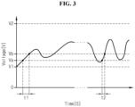
- FIG. 3 shows a change in charge time based on the degradation level of the secondary battery connected to the apparatus for estimating the state of a secondary battery according to another embodiment of the present disclosure.
- the secondary battery 10 connected to the apparatus 1 for estimating the state of a secondary battery according to the present disclosure may be charged and discharged in a preset voltage range.
- the secondary battery 10 connected to the apparatus 1 for estimating the state of a secondary battery may be charged and discharged.
- the graph shown in FIG. 3 shows two measurement times measured at a time interval while the secondary battery 10 is charged and discharged in a preset voltage range V1 ⁇ V2.
- the measurement time t1 and the measurement time t2 are measured at a considerable time interval. For example, there may be a one year time interval between the measurement time t1 and the measurement time t2.
- the time measuring unit 300 may measure the charge time of the secondary battery 10 in the voltage range Va ⁇ Vb corresponding to a predefined voltage range.
- the time measuring unit 300 may measure t1, and measure t2 at a time interval from t1.
- the control unit 400 may calculate a ratio of t2 to t1, and estimate the degradation level of the secondary battery 10 using the calculated ratio. That is, the control unit 400 may estimate the degradation level of the secondary battery 10 according to the ratio of t1 to t2 based on the degradation level pre-stored in the memory unit 500.
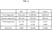
- FIG. 4 shows a change in charge time and a change in ratio of charge time of the secondary battery according to an embodiment of the present disclosure.
- the memory unit 500 may pre-store the degradation level of the secondary battery 10 corresponding to the ratio of charge time.
- the memory unit 500 may store the plurality of charge times received from the time measuring unit 300.
- the memory unit 500 may store the charge time corresponding to the voltage range and the ratio of charge time.
- the BOL charge time of the secondary battery 10 may be 4,611s in the first range, and 263s in the second range.
- the charge time of the total range including the first range and the second range may be 4,874s.
- the charge time after two year use of the secondary battery 10 may be 3,349s in the first range, and 376s in the second range.
- the charge time of the total range including the first range and the second range may be 3,725s.
- the charge time after four year use of the secondary battery 10 may be 3,050s in the first range, and 440s in the second range.
- the charge time of the total range including the first range and the second range may be 3,490s.
- the control unit 400 may receive the charge time of the voltage range from the memory unit 500, and calculate a ratio of charge time. For example, in the embodiment of FIG. 4 , when the BOL charge time of the secondary battery 10 is set to 100%, the charge time after two year use of the secondary battery 10 to the BOL charge time of the secondary battery 10 may be 76.43%, and the charge time after four year use of the secondary battery 10 to the BOL charge time of the secondary battery 10 may be 71.60%.
- the control unit 400 may calculate a ratio of charge time for the first range and a ratio of charge time for the second range. Alternatively, the control unit 400 may calculate a ratio of charge time for the total range.
- the control unit 400 may determine whether the secondary battery 10 needs to be replaced. Particularly, when a ratio of charge time is a predetermined value or less, the control unit 400 may determine that the secondary battery 10 needs to be replaced. In more detail, when a ratio of the second charge time to the first charge time is a predetermined value or less, the control unit 400 may be configured to transmit a replacement signal for the secondary battery 10. For example, when a ratio of the charge time to the BOL charge time of the secondary battery 10 corresponds to 75%, the control unit 400 may determine that the secondary battery 10 needs to be replaced.
- the predetermined value may be differently determined for each secondary battery 10. That is, the predetermined value may be a value that is set independently for each secondary battery 10 based on the initial state of the secondary battery 10. For example, because the predetermined value is different for each secondary battery 10, even though a ratio of the second charge time to the first charge time of the first secondary battery is equal to a ratio of the second charge time to the first charge time of the second secondary battery, a replacement signal for only the first secondary battery may be transmitted.
- the secondary battery 10 used in emergency call application should always have the discharge capacity enough to supply the specific power.
- the predetermined value may be determined for each secondary battery 10 based on a correlation between the discharge capacity (retained capacity) and the charge time of each secondary battery 10. For example, the predetermined value for the first secondary battery may be 75%, the predetermined value for the second secondary battery may be 78%, and the predetermined value for the third secondary battery may be 76%.
- the control unit 400 may determine that the second secondary battery and the third secondary battery need to be replaced, and transmit a replacement signal for the second secondary battery and the third secondary battery. That is, the apparatus 1 for estimating the state of a secondary battery according to an embodiment of the present disclosure individually determines a reference ratio (a predetermined value) for determining whether the secondary battery 10 needs to be replaced based on the initial state of each secondary battery 10, to measure the state of each secondary battery 10 more precisely and accurately.
- a reference ratio a predetermined value
- the apparatus 1 for estimating the state of a secondary battery determines the state of each secondary battery 10 using the absolute time as well as the ratio of charge time. That is, because the apparatus 1 for estimating the state of a secondary battery uses the ratio of charge time of each secondary battery 10, it is possible to determine the state of each secondary battery 10 irrespective of a difference in resistance or capacity between the secondary batteries 10. For example, when the state of the secondary battery 10 is uniformly determined according to the absolute charge time of the secondary battery 10, because a difference in resistance or capacity between the secondary batteries 10 is not taken into account, the degradation level of each secondary battery 10 cannot be accurately measured. That is, even though the charge time is the same, the degradation level may be different depending on the resistance or capacity of the secondary battery 10. Accordingly, when only the absolute charge time is taken into account, it is impossible to accurately measure the state of the secondary battery 10, and thus the apparatus 1 for estimating the state of a secondary battery may measure the state of each secondary battery 10 more accurately than when only the absolute charge time is used.
- the apparatus 1 for estimating the state of a secondary battery according to the present disclosure may be provided in a battery pack in itself. That is, the battery pack according to the present disclosure may include the above-described apparatus for estimating the state of a secondary battery according to the present disclosure.
- the battery pack may include a plurality of secondary batteries, the apparatus for estimating the state of a secondary battery, an electrical component (a BMS, a relay, a fuse, etc.) and a case.
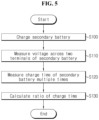
- FIG. 5 is a schematic flowchart showing a method for estimating the state of a secondary battery according to an embodiment of the present disclosure.
- the subject that performs each step may be each component of the previously-described apparatus 1 for estimating the state of a secondary battery according to the present disclosure.
- step S100 the charging unit 100 charges the secondary battery 10.
- step S110 the voltage measuring unit 200 measures the voltage across two terminals of the secondary battery 10.
- step S120 the time measuring unit 300 receives a voltage value of the secondary battery 10, and in a predefined voltage range, measures the charge time of the secondary battery 10 corresponding to the voltage range multiple times during charging of the secondary battery 10.
- step S130 for a first charge time and a second charge time measured sequentially at a time interval, the control unit 400 calculates a ratio of the second charge time to the first charge time, and estimates the state of the secondary battery 10.
- the voltage measuring unit 200 may measure the voltage across the two terminals of the secondary battery 10 when the charge current is continuously supplied from the charging unit 100 to the secondary battery 10.
- control unit 400 may set the charge time at the product sale of the secondary battery 10 as a first charge time and the charge time measured at a time interval from the first charge time as a second charge time, and calculate a ratio of the second charge time to the first charge time.
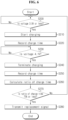
- FIG. 6 is a schematic flowchart showing a method for estimating the state of a secondary battery according to another embodiment of the present disclosure.
- the subject that performs each step may be each component of the previously-described apparatus 1 for estimating the state of a secondary battery according to the present disclosure.
- the charge start voltage (3.9V), the charge end voltage (4.1V) and the predetermined value (75%) for replacement signal transmission shown in FIG. 6 are just an example, and the method for estimating the state of a secondary battery according to an embodiment of the present disclosure is not limited to these values.
- the control unit 400 may determine whether the voltage of the secondary battery 10 corresponds to a charge start voltage.
- the charge start voltage may be 3.9V.
- control unit 400 may transmit a charge start command to the charging unit 100 to enable the charging unit 100 to charge the secondary battery 10 in step S210.
- the control unit 400 may not charge the secondary battery 10.
- the time measuring unit 300 may record the charge time of the secondary battery 10. Particularly, the time measuring unit 300 may start recording the charge time when the charging starts.
- the control unit 400 may determine whether the voltage of the secondary battery 10 corresponds to a charge end voltage.
- the charge end voltage may be 4.1V.
- control unit 400 may transmit a charge end command to the charging unit 100 to enable the charging unit 100 to terminate the charging of the secondary battery 10 in step S240.
- the control unit 400 may keep charging the secondary battery 10.
- the time measuring unit 300 may record the charge time of the secondary battery 10. Particularly, the time measuring unit 300 may terminate the recording of the charge time when the charging ends.
- control unit 400 may calculate a ratio of charge time.
- control unit 400 may receive the charge time from the memory unit 500 or the time measuring unit 300.
- control unit 400 may determine whether the ratio of charge time corresponds to the time to replace. For example, the control unit 400 may determine that it is time to replace when the ratio of charge time is 75% or less.
- the control unit 400 may transmit a replacement signal transmit command to the alarm unit 600 in step S280. Additionally, the alarm unit 600 may transmit a replacement signal based on the command received from the control unit 400. On the contrary, the determination result of the step S270 is NO, the control unit 400 may revert to the step S200 to determine whether the voltage of the secondary battery 10 corresponds to the charge start voltage.
- control unit 400 may be implemented as a set of program modules.
- program module may be stored in the memory device and executed by the processor.
- control logics of the control unit 400 may be combined, and the combined control logics are not limited to a particular type and include any type that can be written in computer-readable coding systems and read and accessed by the computer.
- the recording media may include at least one selected from the group consisting of ROM, RAM, register, CD-ROM, magnetic tape, hard disk, floppy disk and an optical data recording device.
- the coding systems may be stored and executed in computers connected via a network in distributed manner. Additionally, functional programs, codes and segments for implementing the combined control logics may be easily inferred by programs in the technical field pertaining to the present disclosure.
- 'unit' such as 'memory unit' and 'control unit' is used herein, but this indicates a logical component unit and it is obvious to those skilled in the art that the term does not necessarily indicate a component that may be or should be physically separated from other components,
Landscapes
- Physics & Mathematics (AREA)
- General Physics & Mathematics (AREA)
- Engineering & Computer Science (AREA)
- Manufacturing & Machinery (AREA)
- Chemical & Material Sciences (AREA)
- Chemical Kinetics & Catalysis (AREA)
- Electrochemistry (AREA)
- General Chemical & Material Sciences (AREA)
- Power Engineering (AREA)
- Secondary Cells (AREA)
- Charge And Discharge Circuits For Batteries Or The Like (AREA)
- Tests Of Electric Status Of Batteries (AREA)
Claims (7)
- Vorrichtung (1) zum Schätzen eines Zustands einer Sekundärbatterie (10), umfassend:eine Ladeeinheit (100), welche elektrisch mit zwei Anschlüssen der Sekundärbatterie (10) verbindbar ist, um die Sekundärbatterie (10) zu laden;eine Spannungsmesseinheit (200), welche elektrisch mit den beiden Anschlüssen der Sekundärbatterie (10) verbindbar ist, um eine Spannung an den beiden Anschlüssen der Sekundärbatterie (10) zu messen;eine Zeitmesseinheit (300), welche dazu eingerichtet ist, von der Spannungsmesseinheit (200) einen Spannungswert der Sekundärbatterie (10) zu empfangen, und, während eines Ladens der Sekundärbatterie (10), in einem vordefinierten Spannungsbereich (V1-V2), eine Ladezeit der Sekundärbatterie (10), welche dem Spannungsbereich entspricht, sequentiell zu mehreren Zeiten zu messen; undeine Steuereinheit (400), welche dazu eingerichtet ist, ein elektrisches Signal zu und von der Ladeeinheit (100), der Spannungsmesseinheit (200) und der Zeitmesseinheit (300) zu übertragen und zu empfangen, um ein Verhältnis einer ersten Ladezeit (a1, b1, c1) und einer zweiten Ladezeit (a2, b2, c2) der Sekundärbatterie (10) zu berechnen, welche durch die Zeitmesseinheit (300) sequentiell gemessen werden, wobei ein Zeitintervall zwischen sequentielle Berechnungen des Verhältnisses hineinpasst, und um einen Zustand der Sekundärbatterie (10) zu schätzen, wobei der Degradationsgrad der Sekundärbatterie (10) auf Grundlage des Degradationsgrads, welcher im Voraus in einer Speichereinheit (500) gespeichert worden ist, gemäß dem Verhältnis der ersten und der zweiten Ladezeit geschätzt wird; wobei die Speichereinheit (500) dazu eingerichtet ist, den Degradationsgrad der Sekundärbatterie (10) im Voraus zu speichern, welcher dem Verhältnis der zweiten Ladezeit zu der ersten Ladezeit entspricht, welche sequentiell zu mehreren Zeiten gemessen werden;wobei der Spannungsbereich (V1-V2) einen ersten Spannungsbereich (V1), in welchem ein konstanter Ladestrom beibehalten wird, und einen zweiten Spannungsbereich (V2) umfasst, in welchem eine konstante Ladespannung (V2) beibehalten wird, unddie Zeitmesseinheit (300) dazu eingerichtet ist, die Ladezeit (a1+a2; b1+b2; c1+c2) der Sekundärbatterie (10) zu messen, welche jedem des ersten Spannungsbereichs (V1) und des zweiten Spannungsbereichs (V2) entspricht, welche Ladezeit einem Bereich (a1), in welchem ein konstanter Ladestrom beibehalten wird, und zusätzlich einem Bereich entspricht, in welchem die Ladezeit (a2) dem zweiten Spannungsbereich entspricht, in welchem eine konstante Ladespannung beibehalten wird; undwobei die Steuereinheit (400) dazu eingerichtet ist, eine Ladezeit (a1+a2) zu Beginn einer Lebensdauer (BOL) der Sekundärbatterie (10) als die erste Ladezeit (a1+a2) und eine Ladezeit (b1+b2), welche in einem Zeitintervall von der ersten Ladezeit (a1+a2) ab gemessen wird, als die zweite Ladezeit (b1+b2) einzustellen und ein Verhältnis der zweiten Ladezeit (b1+b2) zu der ersten Ladezeit (a1+a2) zu berechnen.
- Vorrichtung (1) zum Schätzen eines Zustands einer Sekundärbatterie (10) nach Anspruch 1, wobei die Spannungsmesseinheit (200) dazu eingerichtet ist, die Spannung an den beiden Anschlüssen der Sekundärbatterie (10) zu messen, wenn ein konstanter Ladestrom kontinuierlich von der Ladeeinheit (100) zu der Sekundärbatterie (10) geliefert wird.
- Vorrichtung (1) zum Schätzen eines Zustands einer Sekundärbatterie (10) nach Anspruch 1, ferner umfassend:
eine Speichereinheit (500), welche den Degradationsgrad der Sekundärbatterie (10) im Voraus speichert, welcher dem Verhältnis der zweiten Ladezeit (a2, b2, c2) zu der ersten Ladezeit (a1, b1, c1) entspricht. - Vorrichtung (1) zum Schätzen eines Zustands einer Sekundärbatterie (10) nach Anspruch 1, ferner umfassend:
eine Alarmeinheit (600), welche dazu eingerichtet ist, ein elektrisches Signal von der Steuereinheit (400) zu empfangen und ein Alarmsignal, welches Informationen umfasst, welche einem Degradationsgrad der Sekundärbatterie (10) zugeordnet sind, auf Grundlage des von der Steuereinheit (400) empfangenen Signals an eine externe Vorrichtung zu übertragen (S280). - Vorrichtung (1) zum Schätzen eines Zustands einer Sekundärbatterie (10) nach Anspruch 4, wobei die Steuereinheit (400) dazu eingerichtet ist, ein Austauschsignal für die Sekundärbatterie (10) an die Alarmeinheit (600) zu übertragen, wenn ein Verhältnis der zweiten Ladezeit (b1+b2) zu der ersten Ladezeit (a1+a2) ein vorbestimmter Wert oder weniger ist.
- Batteriepack, umfassend die Vorrichtung (1) zum Schätzen eines Zustands einer Sekundärbatterie (10) nach einem der Ansprüche 1 bis 5.
- Verfahren zum Schätzen eines Zustands einer Sekundärbatterie (10) unter Verwendung der Vorrichtung nach wenigstens einem der Ansprüche 1 bis 5, umfassend:Laden (S100) der Sekundärbatterie (10);Messen (S110) einer Spannung an zwei Anschlüssen der Sekundärbatterie (10);Empfangen (S120) eines Spannungswerts der Sekundärbatterie (10) und, während des Ladens (S100) der Sekundärbatterie (10), in einem vordefinierten Spannungsbereich (V1-V2), Messen einer Ladezeit (a1+a2; b1+b2; c1+c2) der Sekundärbatterie (10), welche dem Spannungsbereich (V1-V2) entspricht, für mehrere Male; undfür eine erste Ladezeit (a1+a2) und eine zweite Ladezeit (b1+b2) der Sekundärbatterie (10), welche in einem Zeitintervall sequentiell gemessen werden, Berechnen (S130) eines Verhältnisses der zweiten Ladezeit (b1+b2) zu der ersten Ladezeit (a1+a2) und Schätzen eines Zustands der Sekundärbatterie (10).
Applications Claiming Priority (2)
| Application Number | Priority Date | Filing Date | Title |
|---|---|---|---|
| KR1020180016387A KR102442632B1 (ko) | 2018-02-09 | 2018-02-09 | 이차 전지 상태 추정 장치 및 방법 |
| PCT/KR2019/001106 WO2019156403A1 (ko) | 2018-02-09 | 2019-01-25 | 이차 전지 상태 추정 장치 및 방법 |
Publications (3)
| Publication Number | Publication Date |
|---|---|
| EP3674733A1 EP3674733A1 (de) | 2020-07-01 |
| EP3674733A4 EP3674733A4 (de) | 2021-01-06 |
| EP3674733B1 true EP3674733B1 (de) | 2024-09-11 |
Family
ID=67548501
Family Applications (1)
| Application Number | Title | Priority Date | Filing Date |
|---|---|---|---|
| EP19751476.3A Active EP3674733B1 (de) | 2018-02-09 | 2019-01-25 | Vorrichtung und verfahren zur schätzung des zustands einer sekundärbatterie |
Country Status (8)
| Country | Link |
|---|---|
| US (1) | US11340305B2 (de) |
| EP (1) | EP3674733B1 (de) |
| JP (1) | JP7049558B2 (de) |
| KR (1) | KR102442632B1 (de) |
| CN (2) | CN110832333A (de) |
| ES (1) | ES2989197T3 (de) |
| HU (1) | HUE068585T2 (de) |
| WO (1) | WO2019156403A1 (de) |
Families Citing this family (6)
| Publication number | Priority date | Publication date | Assignee | Title |
|---|---|---|---|---|
| FR3105435B1 (fr) * | 2019-12-23 | 2021-11-19 | Renault Sas | Procédé d’identification du début de l’accélération de la dégradation de l’état de santé de batteries d’accumulateurs électriques |
| KR20220116866A (ko) * | 2021-02-16 | 2022-08-23 | 삼성전자주식회사 | 전자 장치 및 그 제어 방법 |
| US12308676B2 (en) | 2021-02-16 | 2025-05-20 | Samsung Electronics Co., Ltd | Electronic device capable of identifying a state of a rechargeable battery |
| CN115579989B (zh) * | 2022-10-26 | 2023-07-04 | 国创巨湾(广州)能源科技有限公司 | 充电控制电路及控制方法 |
| WO2024128352A1 (ko) * | 2022-12-15 | 2024-06-20 | 한국에너지기술연구원 | 배터리 노화상태 추정 장치 및 방법 |
| EP4556922A1 (de) * | 2023-11-14 | 2025-05-21 | Tridonic GmbH & Co. KG | Einheit und verfahren zum testen einer lebensdauer einer batterie als notstromspeicher eines notbeleuchtungssystems |
Family Cites Families (30)
| Publication number | Priority date | Publication date | Assignee | Title |
|---|---|---|---|---|
| JPH07102611B2 (ja) * | 1987-12-09 | 1995-11-08 | 株式会社プラコー | インフレーションフイルム成形方法及びその装置 |
| JP3659772B2 (ja) * | 1997-08-07 | 2005-06-15 | 三菱自動車工業株式会社 | バッテリの劣化判定装置 |
| TW510977B (en) | 2000-03-13 | 2002-11-21 | Nippon Telegraph & Telephone | Capacity estimation method, degradation estimation method and degradation estimation apparatus for lithium-ion cells, and lithium-ion batteries |
| JP3547686B2 (ja) | 2000-04-03 | 2004-07-28 | 日本電信電話株式会社 | リチウムイオン電池の容量推定方法、劣化判定方法および劣化判定装置ならびにリチウムイオン電池パック |
| JP2001292534A (ja) * | 2000-04-04 | 2001-10-19 | Sekisui Chem Co Ltd | リチウムイオン電池の劣化度判定装置 |
| US6586130B1 (en) | 2000-11-22 | 2003-07-01 | Honeywell International Inc. | Method and apparatus for determining the state of charge of a lithium-ion battery |
| ATE489757T1 (de) * | 2001-05-29 | 2010-12-15 | Canon Kk | Verfahren, vorrichtung und programm zur erfassung von internen informationen einer wiederaufladbaren batterie und diese erfassungsvorrichtung enthaltende vorrichtung |
| JP2004193003A (ja) * | 2002-12-12 | 2004-07-08 | Matsushita Electric Ind Co Ltd | 充電制御装置及び携帯端末装置 |
| JP2007078506A (ja) | 2005-09-14 | 2007-03-29 | Matsushita Electric Ind Co Ltd | 二次電池の寿命判定装置 |
| US7573237B2 (en) * | 2006-02-23 | 2009-08-11 | Powercart Systems, Inc. | System and method for monitoring battery state |
| JP5125070B2 (ja) | 2006-11-17 | 2013-01-23 | 富士通株式会社 | 電池制御装置、電池制御方法、電池パック、電子機器、電池制御プログラムおよび制御回路 |
| CN101067644B (zh) | 2007-04-20 | 2010-05-26 | 杭州高特电子设备有限公司 | 蓄电池性能分析专家诊断方法 |
| JP2010252474A (ja) | 2009-04-14 | 2010-11-04 | Nissan Motor Co Ltd | 二次電池の充電方法 |
| CN101908770A (zh) | 2009-06-04 | 2010-12-08 | 魏培伦 | 智能型活化锂电池充电装置 |
| JP5789736B2 (ja) | 2009-10-23 | 2015-10-07 | パナソニックIpマネジメント株式会社 | 電力供給装置 |
| JP2011257219A (ja) | 2010-06-08 | 2011-12-22 | Nissan Motor Co Ltd | 二次電池の内部抵抗又は開放電圧を演算する演算装置 |
| JP5870590B2 (ja) | 2011-09-29 | 2016-03-01 | ミツミ電機株式会社 | 電池状態計測方法及び電池状態計測装置 |
| KR101366416B1 (ko) * | 2011-10-12 | 2014-02-24 | (주)에스엔디파워닉스 | 축전지 수명 진단 기능을 구비한 충전 시스템 |
| KR101454834B1 (ko) | 2012-12-04 | 2014-10-28 | 주식회사 엘지화학 | 이차 전지의 파라미터 추정 장치 및 방법 |
| JP6115260B2 (ja) | 2013-04-01 | 2017-04-19 | マックス株式会社 | 電池パック |
| KR102037378B1 (ko) | 2013-07-04 | 2019-10-28 | 에스케이이노베이션 주식회사 | 정전류시 soc 추정 방법, 장치, 이를 포함하는 배터리 관리 시스템 및 에너지 저장 시스템 |
| CN105453373B (zh) | 2013-08-09 | 2018-03-02 | 日立汽车系统株式会社 | 电池控制系统、车辆控制系统 |
| KR101590375B1 (ko) | 2014-03-17 | 2016-02-01 | 엘지전자 주식회사 | 이동 단말기 및 그 제어방법 |
| KR102225667B1 (ko) | 2014-07-02 | 2021-03-12 | 삼성전자주식회사 | 배터리의 상태를 추정하는 방법 및 장치 |
| US10459034B2 (en) | 2014-12-26 | 2019-10-29 | Samsung Electronics Co., Ltd. | Method and apparatus for estimating state of health (SOH) of battery |
| KR102577581B1 (ko) | 2014-12-26 | 2023-09-12 | 삼성전자주식회사 | 배터리의 성능 상태를 추정하는 방법 및 장치 |
| KR102337489B1 (ko) | 2015-01-08 | 2021-12-09 | 삼성에스디아이 주식회사 | 전기차량의 배터리 soh 추정 시스템 |
| KR102338460B1 (ko) | 2015-01-22 | 2021-12-13 | 삼성전자주식회사 | 배터리의 상태를 추정하는 방법 및 장치 |
| JP6715573B2 (ja) | 2015-06-08 | 2020-07-01 | Nok株式会社 | 基板一体型ガスケットの製造方法 |
| KR102117316B1 (ko) * | 2016-07-06 | 2020-06-01 | 주식회사 엘지화학 | Cc/cv 비율을 이용한 이차전지의 가용 용량 추정 장치 |
-
2018
- 2018-02-09 KR KR1020180016387A patent/KR102442632B1/ko active Active
-
2019
- 2019-01-25 JP JP2019568735A patent/JP7049558B2/ja active Active
- 2019-01-25 US US16/623,136 patent/US11340305B2/en active Active
- 2019-01-25 WO PCT/KR2019/001106 patent/WO2019156403A1/ko not_active Ceased
- 2019-01-25 CN CN201980003371.6A patent/CN110832333A/zh active Pending
- 2019-01-25 CN CN202411397385.XA patent/CN119395583A/zh active Pending
- 2019-01-25 EP EP19751476.3A patent/EP3674733B1/de active Active
- 2019-01-25 HU HUE19751476A patent/HUE068585T2/hu unknown
- 2019-01-25 ES ES19751476T patent/ES2989197T3/es active Active
Also Published As
| Publication number | Publication date |
|---|---|
| EP3674733A4 (de) | 2021-01-06 |
| KR102442632B1 (ko) | 2022-09-08 |
| KR20190096673A (ko) | 2019-08-20 |
| JP7049558B2 (ja) | 2022-04-07 |
| US11340305B2 (en) | 2022-05-24 |
| ES2989197T3 (es) | 2024-11-25 |
| JP2020523973A (ja) | 2020-08-06 |
| WO2019156403A1 (ko) | 2019-08-15 |
| CN110832333A (zh) | 2020-02-21 |
| CN119395583A (zh) | 2025-02-07 |
| EP3674733A1 (de) | 2020-07-01 |
| US20200174083A1 (en) | 2020-06-04 |
| HUE068585T2 (hu) | 2025-01-28 |
Similar Documents
| Publication | Publication Date | Title |
|---|---|---|
| EP3674733B1 (de) | Vorrichtung und verfahren zur schätzung des zustands einer sekundärbatterie | |
| US20240300378A1 (en) | Battery management apparatus, battery management method, battery pack, and electric vehicle | |
| EP3444921B1 (de) | Ladesteuerungsvorrichtung und verfahren zum energieeinsparen und zum schnellen zellenausgleich | |
| KR102351637B1 (ko) | 배터리 관리 장치 및 방법 | |
| EP3672021B1 (de) | Vorrichtung zur verhinderung von überentladung | |
| US10873201B2 (en) | Battery management apparatus and method for protecting a lithium iron phosphate cell from over-voltage using the same | |
| EP3678256B1 (de) | Vorrichtung und verfahren zum testen einer sekundärbatterie | |
| US20120032641A1 (en) | Battery pack and method of controlling the same | |
| US12500433B2 (en) | Battery management apparatus and method | |
| EP3605126B1 (de) | Vorrichtung und verfahren zur soc-schätzung einer batterie | |
| KR20190073925A (ko) | 프리차지 장치 및 방법 | |
| CN115667957B (zh) | 电池管理设备、电池检测装置及电池管理方法 | |
| EP4002638A1 (de) | Batterieverwaltungssystem, batteriepack, elektrofahrzeug und batterieverwaltungsverfahren | |
| EP4024070A1 (de) | Batteriesteuerungsvorrichtung | |
| EP3657593B1 (de) | Batteriepack | |
| US20240322588A1 (en) | Battery control apparatus and method |
Legal Events
| Date | Code | Title | Description |
|---|---|---|---|
| STAA | Information on the status of an ep patent application or granted ep patent |
Free format text: STATUS: THE INTERNATIONAL PUBLICATION HAS BEEN MADE |
|
| PUAI | Public reference made under article 153(3) epc to a published international application that has entered the european phase |
Free format text: ORIGINAL CODE: 0009012 |
|
| STAA | Information on the status of an ep patent application or granted ep patent |
Free format text: STATUS: REQUEST FOR EXAMINATION WAS MADE |
|
| 17P | Request for examination filed |
Effective date: 20200325 |
|
| AK | Designated contracting states |
Kind code of ref document: A1 Designated state(s): AL AT BE BG CH CY CZ DE DK EE ES FI FR GB GR HR HU IE IS IT LI LT LU LV MC MK MT NL NO PL PT RO RS SE SI SK SM TR |
|
| AX | Request for extension of the european patent |
Extension state: BA ME |
|
| REG | Reference to a national code |
Ref country code: DE Ref legal event code: R079 Free format text: PREVIOUS MAIN CLASS: G01R0031392000 Ipc: G01R0031383500 Ref document number: 602019058713 Country of ref document: DE |
|
| A4 | Supplementary search report drawn up and despatched |
Effective date: 20201208 |
|
| RIC1 | Information provided on ipc code assigned before grant |
Ipc: G01R 31/3835 20190101AFI20201202BHEP Ipc: G01R 31/392 20190101ALI20201202BHEP |
|
| DAV | Request for validation of the european patent (deleted) | ||
| DAX | Request for extension of the european patent (deleted) | ||
| RAP1 | Party data changed (applicant data changed or rights of an application transferred) |
Owner name: LG ENERGY SOLUTION LTD. |
|
| RAP3 | Party data changed (applicant data changed or rights of an application transferred) |
Owner name: LG ENERGY SOLUTION, LTD. |
|
| STAA | Information on the status of an ep patent application or granted ep patent |
Free format text: STATUS: EXAMINATION IS IN PROGRESS |
|
| 17Q | First examination report despatched |
Effective date: 20221214 |
|
| GRAP | Despatch of communication of intention to grant a patent |
Free format text: ORIGINAL CODE: EPIDOSNIGR1 |
|
| STAA | Information on the status of an ep patent application or granted ep patent |
Free format text: STATUS: GRANT OF PATENT IS INTENDED |
|
| INTG | Intention to grant announced |
Effective date: 20240516 |
|
| P01 | Opt-out of the competence of the unified patent court (upc) registered |
Free format text: CASE NUMBER: APP_33827/2024 Effective date: 20240606 |
|
| GRAS | Grant fee paid |
Free format text: ORIGINAL CODE: EPIDOSNIGR3 |
|
| GRAA | (expected) grant |
Free format text: ORIGINAL CODE: 0009210 |
|
| STAA | Information on the status of an ep patent application or granted ep patent |
Free format text: STATUS: THE PATENT HAS BEEN GRANTED |
|
| AK | Designated contracting states |
Kind code of ref document: B1 Designated state(s): AL AT BE BG CH CY CZ DE DK EE ES FI FR GB GR HR HU IE IS IT LI LT LU LV MC MK MT NL NO PL PT RO RS SE SI SK SM TR |
|
| REG | Reference to a national code |
Ref country code: GB Ref legal event code: FG4D |
|
| REG | Reference to a national code |
Ref country code: CH Ref legal event code: EP |
|
| REG | Reference to a national code |
Ref country code: DE Ref legal event code: R096 Ref document number: 602019058713 Country of ref document: DE |
|
| REG | Reference to a national code |
Ref country code: IE Ref legal event code: FG4D |
|
| REG | Reference to a national code |
Ref country code: ES Ref legal event code: FG2A Ref document number: 2989197 Country of ref document: ES Kind code of ref document: T3 Effective date: 20241125 |
|
| REG | Reference to a national code |
Ref country code: LT Ref legal event code: MG9D |
|
| PG25 | Lapsed in a contracting state [announced via postgrant information from national office to epo] |
Ref country code: NO Free format text: LAPSE BECAUSE OF FAILURE TO SUBMIT A TRANSLATION OF THE DESCRIPTION OR TO PAY THE FEE WITHIN THE PRESCRIBED TIME-LIMIT Effective date: 20241211 |
|
| REG | Reference to a national code |
Ref country code: NL Ref legal event code: MP Effective date: 20240911 |
|
| PG25 | Lapsed in a contracting state [announced via postgrant information from national office to epo] |
Ref country code: GR Free format text: LAPSE BECAUSE OF FAILURE TO SUBMIT A TRANSLATION OF THE DESCRIPTION OR TO PAY THE FEE WITHIN THE PRESCRIBED TIME-LIMIT Effective date: 20241212 Ref country code: FI Free format text: LAPSE BECAUSE OF FAILURE TO SUBMIT A TRANSLATION OF THE DESCRIPTION OR TO PAY THE FEE WITHIN THE PRESCRIBED TIME-LIMIT Effective date: 20240911 |
|
| PG25 | Lapsed in a contracting state [announced via postgrant information from national office to epo] |
Ref country code: BG Free format text: LAPSE BECAUSE OF FAILURE TO SUBMIT A TRANSLATION OF THE DESCRIPTION OR TO PAY THE FEE WITHIN THE PRESCRIBED TIME-LIMIT Effective date: 20240911 |
|
| PG25 | Lapsed in a contracting state [announced via postgrant information from national office to epo] |
Ref country code: LV Free format text: LAPSE BECAUSE OF FAILURE TO SUBMIT A TRANSLATION OF THE DESCRIPTION OR TO PAY THE FEE WITHIN THE PRESCRIBED TIME-LIMIT Effective date: 20240911 |
|
| PG25 | Lapsed in a contracting state [announced via postgrant information from national office to epo] |
Ref country code: HR Free format text: LAPSE BECAUSE OF FAILURE TO SUBMIT A TRANSLATION OF THE DESCRIPTION OR TO PAY THE FEE WITHIN THE PRESCRIBED TIME-LIMIT Effective date: 20240911 |
|
| PG25 | Lapsed in a contracting state [announced via postgrant information from national office to epo] |
Ref country code: RS Free format text: LAPSE BECAUSE OF FAILURE TO SUBMIT A TRANSLATION OF THE DESCRIPTION OR TO PAY THE FEE WITHIN THE PRESCRIBED TIME-LIMIT Effective date: 20241211 |
|
| REG | Reference to a national code |
Ref country code: HU Ref legal event code: AG4A Ref document number: E068585 Country of ref document: HU |
|
| PG25 | Lapsed in a contracting state [announced via postgrant information from national office to epo] |
Ref country code: RS Free format text: LAPSE BECAUSE OF FAILURE TO SUBMIT A TRANSLATION OF THE DESCRIPTION OR TO PAY THE FEE WITHIN THE PRESCRIBED TIME-LIMIT Effective date: 20241211 Ref country code: NO Free format text: LAPSE BECAUSE OF FAILURE TO SUBMIT A TRANSLATION OF THE DESCRIPTION OR TO PAY THE FEE WITHIN THE PRESCRIBED TIME-LIMIT Effective date: 20241211 Ref country code: LV Free format text: LAPSE BECAUSE OF FAILURE TO SUBMIT A TRANSLATION OF THE DESCRIPTION OR TO PAY THE FEE WITHIN THE PRESCRIBED TIME-LIMIT Effective date: 20240911 Ref country code: HR Free format text: LAPSE BECAUSE OF FAILURE TO SUBMIT A TRANSLATION OF THE DESCRIPTION OR TO PAY THE FEE WITHIN THE PRESCRIBED TIME-LIMIT Effective date: 20240911 Ref country code: GR Free format text: LAPSE BECAUSE OF FAILURE TO SUBMIT A TRANSLATION OF THE DESCRIPTION OR TO PAY THE FEE WITHIN THE PRESCRIBED TIME-LIMIT Effective date: 20241212 Ref country code: FI Free format text: LAPSE BECAUSE OF FAILURE TO SUBMIT A TRANSLATION OF THE DESCRIPTION OR TO PAY THE FEE WITHIN THE PRESCRIBED TIME-LIMIT Effective date: 20240911 Ref country code: BG Free format text: LAPSE BECAUSE OF FAILURE TO SUBMIT A TRANSLATION OF THE DESCRIPTION OR TO PAY THE FEE WITHIN THE PRESCRIBED TIME-LIMIT Effective date: 20240911 |
|
| REG | Reference to a national code |
Ref country code: AT Ref legal event code: MK05 Ref document number: 1723161 Country of ref document: AT Kind code of ref document: T Effective date: 20240911 |
|
| PG25 | Lapsed in a contracting state [announced via postgrant information from national office to epo] |
Ref country code: NL Free format text: LAPSE BECAUSE OF FAILURE TO SUBMIT A TRANSLATION OF THE DESCRIPTION OR TO PAY THE FEE WITHIN THE PRESCRIBED TIME-LIMIT Effective date: 20240911 |
|
| PG25 | Lapsed in a contracting state [announced via postgrant information from national office to epo] |
Ref country code: PT Free format text: LAPSE BECAUSE OF FAILURE TO SUBMIT A TRANSLATION OF THE DESCRIPTION OR TO PAY THE FEE WITHIN THE PRESCRIBED TIME-LIMIT Effective date: 20250113 Ref country code: IS Free format text: LAPSE BECAUSE OF FAILURE TO SUBMIT A TRANSLATION OF THE DESCRIPTION OR TO PAY THE FEE WITHIN THE PRESCRIBED TIME-LIMIT Effective date: 20250111 |
|
| PG25 | Lapsed in a contracting state [announced via postgrant information from national office to epo] |
Ref country code: RO Free format text: LAPSE BECAUSE OF FAILURE TO SUBMIT A TRANSLATION OF THE DESCRIPTION OR TO PAY THE FEE WITHIN THE PRESCRIBED TIME-LIMIT Effective date: 20240911 Ref country code: SM Free format text: LAPSE BECAUSE OF FAILURE TO SUBMIT A TRANSLATION OF THE DESCRIPTION OR TO PAY THE FEE WITHIN THE PRESCRIBED TIME-LIMIT Effective date: 20240911 |
|
| PG25 | Lapsed in a contracting state [announced via postgrant information from national office to epo] |
Ref country code: EE Free format text: LAPSE BECAUSE OF FAILURE TO SUBMIT A TRANSLATION OF THE DESCRIPTION OR TO PAY THE FEE WITHIN THE PRESCRIBED TIME-LIMIT Effective date: 20240911 Ref country code: AT Free format text: LAPSE BECAUSE OF FAILURE TO SUBMIT A TRANSLATION OF THE DESCRIPTION OR TO PAY THE FEE WITHIN THE PRESCRIBED TIME-LIMIT Effective date: 20240911 |
|
| PG25 | Lapsed in a contracting state [announced via postgrant information from national office to epo] |
Ref country code: CZ Free format text: LAPSE BECAUSE OF FAILURE TO SUBMIT A TRANSLATION OF THE DESCRIPTION OR TO PAY THE FEE WITHIN THE PRESCRIBED TIME-LIMIT Effective date: 20240911 Ref country code: PL Free format text: LAPSE BECAUSE OF FAILURE TO SUBMIT A TRANSLATION OF THE DESCRIPTION OR TO PAY THE FEE WITHIN THE PRESCRIBED TIME-LIMIT Effective date: 20240911 |
|
| PG25 | Lapsed in a contracting state [announced via postgrant information from national office to epo] |
Ref country code: SK Free format text: LAPSE BECAUSE OF FAILURE TO SUBMIT A TRANSLATION OF THE DESCRIPTION OR TO PAY THE FEE WITHIN THE PRESCRIBED TIME-LIMIT Effective date: 20240911 Ref country code: IT Free format text: LAPSE BECAUSE OF FAILURE TO SUBMIT A TRANSLATION OF THE DESCRIPTION OR TO PAY THE FEE WITHIN THE PRESCRIBED TIME-LIMIT Effective date: 20240911 |
|
| REG | Reference to a national code |
Ref country code: DE Ref legal event code: R097 Ref document number: 602019058713 Country of ref document: DE |
|
| PG25 | Lapsed in a contracting state [announced via postgrant information from national office to epo] |
Ref country code: DK Free format text: LAPSE BECAUSE OF FAILURE TO SUBMIT A TRANSLATION OF THE DESCRIPTION OR TO PAY THE FEE WITHIN THE PRESCRIBED TIME-LIMIT Effective date: 20240911 |
|
| PLBE | No opposition filed within time limit |
Free format text: ORIGINAL CODE: 0009261 |
|
| STAA | Information on the status of an ep patent application or granted ep patent |
Free format text: STATUS: NO OPPOSITION FILED WITHIN TIME LIMIT |
|
| 26N | No opposition filed |
Effective date: 20250612 |
|
| REG | Reference to a national code |
Ref country code: CH Ref legal event code: PL |
|
| PG25 | Lapsed in a contracting state [announced via postgrant information from national office to epo] |
Ref country code: SE Free format text: LAPSE BECAUSE OF FAILURE TO SUBMIT A TRANSLATION OF THE DESCRIPTION OR TO PAY THE FEE WITHIN THE PRESCRIBED TIME-LIMIT Effective date: 20240911 |
|
| PG25 | Lapsed in a contracting state [announced via postgrant information from national office to epo] |
Ref country code: MC Free format text: LAPSE BECAUSE OF FAILURE TO SUBMIT A TRANSLATION OF THE DESCRIPTION OR TO PAY THE FEE WITHIN THE PRESCRIBED TIME-LIMIT Effective date: 20240911 Ref country code: LU Free format text: LAPSE BECAUSE OF NON-PAYMENT OF DUE FEES Effective date: 20250125 |
|
| PG25 | Lapsed in a contracting state [announced via postgrant information from national office to epo] |
Ref country code: CH Free format text: LAPSE BECAUSE OF NON-PAYMENT OF DUE FEES Effective date: 20250131 |
|
| PGFP | Annual fee paid to national office [announced via postgrant information from national office to epo] |
Ref country code: GB Payment date: 20251222 Year of fee payment: 8 |
|
| PGFP | Annual fee paid to national office [announced via postgrant information from national office to epo] |
Ref country code: FR Payment date: 20251223 Year of fee payment: 8 |
|
| PGFP | Annual fee paid to national office [announced via postgrant information from national office to epo] |
Ref country code: BE Payment date: 20251229 Year of fee payment: 8 |
|
| PG25 | Lapsed in a contracting state [announced via postgrant information from national office to epo] |
Ref country code: IE Free format text: LAPSE BECAUSE OF NON-PAYMENT OF DUE FEES Effective date: 20250125 |
|
| PGFP | Annual fee paid to national office [announced via postgrant information from national office to epo] |
Ref country code: HU Payment date: 20260129 Year of fee payment: 8 |
|
| PGFP | Annual fee paid to national office [announced via postgrant information from national office to epo] |
Ref country code: ES Payment date: 20260212 Year of fee payment: 8 |
|
| PGFP | Annual fee paid to national office [announced via postgrant information from national office to epo] |
Ref country code: DE Payment date: 20251222 Year of fee payment: 8 |