EP3674637A1 - Kühlgerät - Google Patents
Kühlgerät Download PDFInfo
- Publication number
- EP3674637A1 EP3674637A1 EP19214625.6A EP19214625A EP3674637A1 EP 3674637 A1 EP3674637 A1 EP 3674637A1 EP 19214625 A EP19214625 A EP 19214625A EP 3674637 A1 EP3674637 A1 EP 3674637A1
- Authority
- EP
- European Patent Office
- Prior art keywords
- fluid
- shelf
- refrigerating appliance
- fluid container
- spigot
- Prior art date
- Legal status (The legal status is an assumption and is not a legal conclusion. Google has not performed a legal analysis and makes no representation as to the accuracy of the status listed.)
- Withdrawn
Links
Images


Classifications
-
- F—MECHANICAL ENGINEERING; LIGHTING; HEATING; WEAPONS; BLASTING
- F25—REFRIGERATION OR COOLING; COMBINED HEATING AND REFRIGERATION SYSTEMS; HEAT PUMP SYSTEMS; MANUFACTURE OR STORAGE OF ICE; LIQUEFACTION SOLIDIFICATION OF GASES
- F25D—REFRIGERATORS; COLD ROOMS; ICE-BOXES; COOLING OR FREEZING APPARATUS NOT OTHERWISE PROVIDED FOR
- F25D23/00—General constructional features
- F25D23/12—Arrangements of compartments additional to cooling compartments; Combinations of refrigerators with other equipment, e.g. stove
- F25D23/126—Water cooler
-
- B—PERFORMING OPERATIONS; TRANSPORTING
- B67—OPENING, CLOSING OR CLEANING BOTTLES, JARS OR SIMILAR CONTAINERS; LIQUID HANDLING
- B67D—DISPENSING, DELIVERING OR TRANSFERRING LIQUIDS, NOT OTHERWISE PROVIDED FOR
- B67D3/00—Apparatus or devices for controlling flow of liquids under gravity from storage containers for dispensing purposes
- B67D3/0003—Apparatus or devices for controlling flow of liquids under gravity from storage containers for dispensing purposes provided with automatic fluid control means
-
- B—PERFORMING OPERATIONS; TRANSPORTING
- B67—OPENING, CLOSING OR CLEANING BOTTLES, JARS OR SIMILAR CONTAINERS; LIQUID HANDLING
- B67D—DISPENSING, DELIVERING OR TRANSFERRING LIQUIDS, NOT OTHERWISE PROVIDED FOR
- B67D3/00—Apparatus or devices for controlling flow of liquids under gravity from storage containers for dispensing purposes
- B67D3/0025—Apparatus or devices for controlling flow of liquids under gravity from storage containers for dispensing purposes provided with dispensing valves actuated by the receptacle to be filled
-
- B—PERFORMING OPERATIONS; TRANSPORTING
- B67—OPENING, CLOSING OR CLEANING BOTTLES, JARS OR SIMILAR CONTAINERS; LIQUID HANDLING
- B67D—DISPENSING, DELIVERING OR TRANSFERRING LIQUIDS, NOT OTHERWISE PROVIDED FOR
- B67D3/00—Apparatus or devices for controlling flow of liquids under gravity from storage containers for dispensing purposes
- B67D3/0058—Details
- B67D3/0093—Level indicators
-
- F—MECHANICAL ENGINEERING; LIGHTING; HEATING; WEAPONS; BLASTING
- F25—REFRIGERATION OR COOLING; COMBINED HEATING AND REFRIGERATION SYSTEMS; HEAT PUMP SYSTEMS; MANUFACTURE OR STORAGE OF ICE; LIQUEFACTION SOLIDIFICATION OF GASES
- F25D—REFRIGERATORS; COLD ROOMS; ICE-BOXES; COOLING OR FREEZING APPARATUS NOT OTHERWISE PROVIDED FOR
- F25D25/00—Charging, supporting, and discharging the articles to be cooled
- F25D25/02—Charging, supporting, and discharging the articles to be cooled by shelves
-
- F—MECHANICAL ENGINEERING; LIGHTING; HEATING; WEAPONS; BLASTING
- F25—REFRIGERATION OR COOLING; COMBINED HEATING AND REFRIGERATION SYSTEMS; HEAT PUMP SYSTEMS; MANUFACTURE OR STORAGE OF ICE; LIQUEFACTION SOLIDIFICATION OF GASES
- F25D—REFRIGERATORS; COLD ROOMS; ICE-BOXES; COOLING OR FREEZING APPARATUS NOT OTHERWISE PROVIDED FOR
- F25D29/00—Arrangement or mounting of control or safety devices
-
- G—PHYSICS
- G01—MEASURING; TESTING
- G01F—MEASURING VOLUME, VOLUME FLOW, MASS FLOW OR LIQUID LEVEL; METERING BY VOLUME
- G01F13/00—Apparatus for measuring by volume and delivering fluids or fluent solid materials, not provided for in the preceding groups
-
- G—PHYSICS
- G01—MEASURING; TESTING
- G01F—MEASURING VOLUME, VOLUME FLOW, MASS FLOW OR LIQUID LEVEL; METERING BY VOLUME
- G01F15/00—Details of, or accessories for, apparatus of groups G01F1/00 - G01F13/00 insofar as such details or appliances are not adapted to particular types of such apparatus
- G01F15/001—Means for regulating or setting the meter for a predetermined quantity
- G01F15/003—Means for regulating or setting the meter for a predetermined quantity using electromagnetic, electric or electronic means
-
- F—MECHANICAL ENGINEERING; LIGHTING; HEATING; WEAPONS; BLASTING
- F25—REFRIGERATION OR COOLING; COMBINED HEATING AND REFRIGERATION SYSTEMS; HEAT PUMP SYSTEMS; MANUFACTURE OR STORAGE OF ICE; LIQUEFACTION SOLIDIFICATION OF GASES
- F25D—REFRIGERATORS; COLD ROOMS; ICE-BOXES; COOLING OR FREEZING APPARATUS NOT OTHERWISE PROVIDED FOR
- F25D2323/00—General constructional features not provided for in other groups of this subclass
- F25D2323/122—General constructional features not provided for in other groups of this subclass the refrigerator is characterised by a water tank for the water/ice dispenser
-
- F—MECHANICAL ENGINEERING; LIGHTING; HEATING; WEAPONS; BLASTING
- F25—REFRIGERATION OR COOLING; COMBINED HEATING AND REFRIGERATION SYSTEMS; HEAT PUMP SYSTEMS; MANUFACTURE OR STORAGE OF ICE; LIQUEFACTION SOLIDIFICATION OF GASES
- F25D—REFRIGERATORS; COLD ROOMS; ICE-BOXES; COOLING OR FREEZING APPARATUS NOT OTHERWISE PROVIDED FOR
- F25D2400/00—General features of, or devices for refrigerators, cold rooms, ice-boxes, or for cooling or freezing apparatus not covered by any other subclass
- F25D2400/06—Refrigerators with a vertical mullion
-
- F—MECHANICAL ENGINEERING; LIGHTING; HEATING; WEAPONS; BLASTING
- F25—REFRIGERATION OR COOLING; COMBINED HEATING AND REFRIGERATION SYSTEMS; HEAT PUMP SYSTEMS; MANUFACTURE OR STORAGE OF ICE; LIQUEFACTION SOLIDIFICATION OF GASES
- F25D—REFRIGERATORS; COLD ROOMS; ICE-BOXES; COOLING OR FREEZING APPARATUS NOT OTHERWISE PROVIDED FOR
- F25D2400/00—General features of, or devices for refrigerators, cold rooms, ice-boxes, or for cooling or freezing apparatus not covered by any other subclass
- F25D2400/36—Visual displays
- F25D2400/361—Interactive visual displays
Definitions
- the device is in the field of refrigerating appliances, and more specifically, a water delivery system for providing prefilled containers of water that can be removed and dispensed by the user.
- a refrigerating appliance in at least one aspect, includes a structural cabinet having an inner liner and an outer wrapper that define an insulating cavity.
- the inner liner defines a refrigerating compartment.
- a water dispensing system has at least one fluid outlet.
- a shelf is positioned within the refrigerating compartment.
- the shelf includes a shelf spigot of the water dispensing system.
- the shelf spigot is positioned below an underside of the shelf.
- a fluid level sensor monitors a fluid level of a fluid container that is selectively positioned within a fill zone located below the shelf spigot. The fluid level sensor is in communication with the water dispensing system.
- a refrigerating appliance in at least another aspect, includes a structural cabinet having an inner liner that defines a refrigerating compartment.
- a water dispensing system is coupled to the structural cabinet and having at least one fluid outlet.
- a shelf is coupled with the inner liner and positioned within the refrigerating compartment.
- the shelf includes a plurality of shelf spigots of the at least one fluid outlet.
- the plurality of shelf spigots are positioned below an underside of the shelf.
- a plurality of removable fluid containers are in communication with the plurality of shelf spigots.
- the plurality of shelf spigots are positioned below the underside of the shelf.
- Fluid level sensors are in communication with respective fluid containers of the plurality of removable fluid containers. The fluid level sensors are in communication with the water dispensing system.
- a fluid delivery system for an appliance includes a fluid line in selective communication with a fluid source.
- a shelf defines a fill zone positioned below an underside of the shelf.
- a shelf spigot is coupled with the fluid line and disposed proximate the underside of the shelf and over the fill zone.
- a fluid level sensor is positioned in communication with the fill zone. The fluid level sensor is also in communication with a controller that regulates a flow of fluid through the shelf spigot.
- the terms "upper,” “lower,” “right,” “left,” “rear,” “front,” “vertical,” “horizontal,” and derivatives thereof shall relate to the device as oriented in FIG. 1 .
- the device may assume various alternative orientations and step sequences, except where expressly specified to the contrary.
- the specific devices and processes illustrated in the attached drawings, and described in the following specification are simply exemplary embodiments of the inventive concepts defined in the appended claims. Hence, specific dimensions and other physical characteristics relating to the embodiments disclosed herein are not to be considered as limiting, unless the claims expressly state otherwise.
- reference numeral 10 generally refers to a prefilling water dispenser that is incorporated within a water dispensing system 12 for an appliance 14.
- the prefilling water dispenser 10 is configured to provide water 16 into removable fluid containers 18 that can be cooled within a refrigerating compartment 20 and then removed for use as needed by the user.
- a refrigerating appliance 14 includes a structural cabinet 22 having an inner liner 24 and an outer wrapper 26 that define an insulating cavity 28.
- the inner liner 24 also defines the refrigerating compartment 20 within the structural cabinet 22.
- a water dispensing system 12 is included within the structural cabinet 22 and includes at least one fluid outlet 30.
- a shelf 32 is positioned within a refrigerating compartment 20.
- the shelf 32 includes a shelf spigot 34 of the water dispensing system 12.
- the shelf spigot 34 is typically positioned below, and attached to, an underside 36 of the shelf 32.
- a fluid level sensor 38 is included proximate the shelf spigot 34.
- the fluid level sensor 38 monitors a fluid level 40 of a dispensed fluid 42 within a removable fluid container 18 that is selectively positioned within a fill zone 44 located below the shelf spigot 34.
- the fluid level sensor 38 is in communication with the water dispensing system 12. When the fluid level sensor 38 monitors that the dispensed fluid 42 is approaching or is at a predetermined fill level within the fluid dispenser, the fluid level sensor 38 can communicate with a controller 46 to stop a flow of dispensed fluid 42 from the shelf spigot 34.
- the shelf 32 disposed within the appliance 14 can typically include a rail assembly 60 that receives the removable fluid container 18 that operates with the shelf spigot 34 when the removable fluid container 18 is in an installed position 62.
- the rail assembly 60 can include one or more sliding rails 64 that are adapted to receive grooves 66 that are defined within a portion of the removable fluid container 18.
- the rail assembly 60 can also include snap-type portions or a threaded mechanism 154 (shown in FIG. 8 ) that receives a removable fluid container 18 within a dedicated portion 68 of the fill zone 44.
- the rail assembly 60 is configured to receive at least one removable fluid container 18. It is also contemplated that the rail assembly 60 can receive a plurality of removable fluid containers 18.
- the shelf spigot 34 may include a plurality of fluid ports 70 or outlet ports that selectively and independently dispense a dispensed fluid 42 into a dedicated removable fluid container 18.
- a dedicated removable fluid container 18 or one of a plurality of removable fluid containers 18 can slidably engage the rail assembly 60 to define an installed position 62 that is within the fill zone 44.
- the installed position 62 or fill position of the various removable fluid containers 18 are typically positioned beneath an outlet fluid port 70 that is part of the shelf spigot 34.
- the shelf spigot 34 can include an elongated housing 80 that extends from a portion of the structural cabinet 22.
- the elongated housing 80 can contain one or more fluid lines 82, where each dedicated fluid line 82 is configured to be delivered to separate fluid ports 70 of the shelf spigot 34.
- a single fluid port 70 is included within the shelf spigot 34
- a single dedicated fluid line 82 is adapted to be positioned within the elongated housing 80 of the shelf spigot 34.
- a single fluid line 82 can be adapted to deliver fluid, typically water 16, through the various fluid ports 70 of the shelf spigot 34.
- the fluid line 82 can include one or more valves 136 that can operate to provide a delivered fluid into the fill zone 44 for filling a removable fluid container 18.
- the elongated housing 80 can include multiple fluid lines 82.
- each fluid line 82 can represent a dedicated fluid line 82 that serves a single fluid port 70 of the shelf spigot 34.
- the elongated housing 80 of the shelf spigot 34 is configured to cooperatively engage a lid 90 of the dedicated removable fluid container 18.
- the rail system is configured to support the dedicated removable fluid container 18 and also position an opening 92 within the lid 90 of the removable fluid container 18 within the fill zone 44 underneath a fluid port 70 of the shelf spigot 34.
- the elongated housing 80 can matingly fit within an aperture 94 defined within the lid 90 for the dedicated removable fluid container 18. This mating engagement between the elongated housing 80 and the lid 90 for the removable fluid container 18 can be adapted to minimize splashing, leakage, and other occurrences where dispensed fluid 42 is disposed outside of the dedicated removable fluid container 18.
- the dedicated removable fluid container 18 can include sliding members or grooves 66 that are located proximate the lid 90 for the removable fluid container 18. These grooves 66 can be in the form of contoured portions of side walls for the removable fluid container 18. These contoured portions or grooves 66 are configured to slidably engage the sliding rails 64 of the rail assembly 60 for moving the removable fluid container 18 into the installed position 62 for filling within the fill zone 44.
- the aperture 94 within the lid 90 that matingly receives the elongated housing 80 can also serve as a stop or bumper 96 for limiting the inward movement of the removable fluid container 18 into the installed position 62. Through this bumper 96, the cooperation of the lid 90 and the elongated housing 80 can serve to properly position the removable fluid container 18 in the fill zone 44.
- the bottom surface of the elongated housing 80 is contained within the interior volume 98 of the removable fluid container 18 such that the fluid port 70 is entirely contained within the interior volume 98 of the removable fluid container 18.
- a pour spout 100 for the removable fluid container 18 can be offset from a surface of the elongated housing 80. Through this offset configuration, a space is provided to allow for equalization of pressure between the interior volume 98 of the removable fluid container 18 and the areas surrounding the removable fluid container 18.
- the shelf spigot 34 can include a plurality of fluid ports 70 that cooperatively define a fill zone 44.
- each fluid port 70 defines a dedicated portion 68 of the fill zone 44.
- each fluid port 70 in each of the dedicated portions 68 of the fill zone 44 are configured to respectively receive a removable fluid container 18 of plurality of removable fluid containers 18.
- separate removable fluid containers 18 can be attached with the rail assembly 60 for defining the installed position 62 of each of the removable fluid containers 18.
- the rail assembly 60 can be configured to slidably engage each of the plurality of removable fluid containers 18.
- each of the plurality of removable fluid containers 18 can be rotatingly engaged with a threaded portion of the elongated housing 80 of the fill spigot or the rail assembly 60 of the shelf 32. It should be understood that various types of engagements between the removable fluid containers 18 and the rail assembly 60 or the elongated housing 80 are possible. Such engagements are adapted to be robust enough to support, from an underside 36 of the shelf 32, the dedicated removable fluid containers 18 and the dispensed fluid 42 contained therein.
- the elongated housing 80 in certain aspects of the device, can be integrally formed within a portion of the shelf 32. Accordingly, the elongated housing 80 can include a portion of the shelf 32, within which the fluid line 82 or fluid lines 82 are run for delivering water 16 to the shelf spigot 34 that can include the plurality of fluid ports 70. In such an embodiment, the elongated housing 80 can define a top surface 120 of the shelf 32. Accordingly, this top surface 120 of the shelf 32, which includes the elongated housing 80, can provide space upon which various items can be stored within the refrigerating compartment 20.
- a front portion 122 or nose of the elongated housing 80 can define a user interface 124 for operating the shelf spigot 34 that includes the one or more fluid ports 70.
- the shelf spigot 34 can include the plurality of fluid ports 70. These various fluid ports 70 are configured to direct a dispensed fluid 42 in a generally downward direction and into the fill zone 44.
- dedicated portions 68 of this fill zone 44 can be reserved for dedicated removable fluid containers 18 that can be engaged with the rail assembly 60 for holding the dedicated removable fluid container 18 in the installed position 62 relative to the fluid ports 70.
- one of the fluid ports 70 can define a user accessible portion 130 of the fill zone 44.
- This user accessible portion 130 is configured to selectively receive an external fluid container 132.
- This external fluid container 132 can be in the form of a glass, pitcher, bowl, flexible member, absorbent material, or other similar material or container that can be used to hold dispensed fluid 42 therein.
- the plurality of removable fluid containers 18 can correspond to the dedicated portions 68 of the fill zone 44 that are distal from the user accessible portion 130.
- the user accessible portion 130 may not include usable portions of the rail assembly 60.
- the external fluid container 132 can be moved substantially close to the fluid port 70 that defines the user accessible portion 130.
- dispensed fluid 42 can be dispensed into the external fluid container 132.
- the user accessible portion 130 can be operated by a fluid level sensor 38, proximity sensor 134, or other similar positioning sensor that can detect the presence of an external fluid container 132 within the user accessible portion 130.
- the controller 46 for the water dispensing system 12 can activate a valve 136 to dispense a dispensed fluid 42 into the user accessible portion 130 upon sensing that an external fluid container 132 is properly positioned in the user accessible portion 130.
- the user interface 124 can be used to either manually activate a valve 136 for providing dispensed water 16, or for communicating to a controller 46 to activate the valve 136 for providing dispensed fluid 42 into the user accessible portion 130.
- one or more fluid level sensors 38 can be incorporated with the shelf spigot 34 for monitoring the amount of dispensed fluid 42 within a dedicated removable fluid container 18 or an external fluid container 132 within a user accessible portion 130 that includes a dedicated user accessible shelf spigot 34 or fluid outlet 30.
- These various sensors can include, but are not limited to, proximity sensors 134, fluid level sensors 38, pressure sensors, weight scales, floats, lasers, ultrasonic sensors, infrared sensors, cameras, microphones, and various other sensors that can be used to determine an amount of dispensed fluid 42 within a particular removable fluid container 18 or external fluid container 132.
- the sensors of the shelf spigot 34 can also be incorporated to monitor the presence of a dedicated removable fluid container 18 or an external fluid container 132.
- a controller 46 can monitor and evaluate whether a container is appropriately in an installed position 62 within a dedicated portion 68 of the fill zone 44.
- the controller 46 can also evaluate the amount of dispensed fluid 42 within the dedicated fluid container for operating a valve 136 to stop the flow of dispensed fluid 42 therein.
- the controller 46 can use the fluid level sensor 38 and the container detection sensors for assessing a user accessible portion 130 for monitoring when an external fluid container 132 is positioned in an installed position 62 to receive dispensed water 16 from a fluid port 70.
- the fluid level sensor 38 can also assess the amount of dispensed fluid 42 contained within the external fluid container 132.
- the rail assembly 60 that cooperates with the elongated housing 80 and the shelf spigot 34 is configured to define the installed position 62 of the dedicated removable fluid container 18.
- the installed position 62 of the dedicated removable fluid container 18 can be defined by the removable fluid container 18 being engaged with the rail assembly 60 and also suspended from the rail assembly 60 so that the removable fluid container 18 is suspended above a vertically adjacent shelf 150.
- movement of the removable fluid container 18 from the installed position 62 to a removed position 152, separate from the rail assembly 60 can be a convenient sliding motion that involves only movement of the removable fluid container 18 with respect to the rail assembly 60.
- a threaded mechanism 154 can be used for placing a dedicated removable fluid container 18 within the installed position 62.
- the space above the vertically adjacent shelf 150 provides for a vertical movement that coincides with operation of the threaded mechanism 154 of the dedicated removable fluid container 18 with respect to the elongated housing 80 of the shelf spigot 34.
- the refrigerating appliance 14 can include the structural cabinet 22 having the inner liner 24 that defines the refrigerating compartment 20.
- the water dispensing system 12 is coupled to the structural cabinet 22 and includes at least one fluid outlet 30.
- the shelf 32 is coupled with the inner liner 24 and is positioned within the refrigerating compartment 20.
- the shelf 32 includes a plurality of shelf spigots 34 that make up the at least one fluid port 70.
- the plurality of shelf spigots 34 are positioned below an underside 36 of the shelf 32.
- a plurality of removable fluid containers 18 can be placed in communication with the plurality of shelf spigots 34, respectively.
- the plurality of shelf spigots 34 can be positioned below an underside 36 of the shelf 32.
- Fluid level sensors 38 are positioned proximate the shelf 32 and can be positioned below the shelf 32 and are in communication with the respective removable fluid containers 18 of the plurality of removable fluid containers 18.
- the fluid level sensors 38 are also in communication with the water dispensing system 12, and in particular, a controller 46 for the water dispensing system 12.
- the rail assembly 60 for the plurality of shelf spigots 34 selectively receives and supports a plurality of removable fluid containers 18 within the fill zone 44 that corresponds to dedicated shelf spigots 34 of the plurality of shelf spigots 34.
- the plurality of shelf spigots 34 may be referred to as fluid ports 70.
- One of these fluid ports 70 can include the user-accessible fluid port 70 that is distal from the rail assembly 60.
- the user-accessible fluid port 70 is configured to define the user accessible portion 130.
- each shelf spigot 34 is configured to be in communication with a dedicated fluid line 82 and a dedicated fluid level sensor 38 of the various fluid level sensors 38.
- each shelf spigot 34 can include a plurality of fluid ports 70 that dispense a dispensed fluid 42 into the fill zone 44.
- the plurality of removable fluid containers 18 are configured to engage the rail assembly 60 to define the installed position 62 within a dedicated portion 68 of the fill zone 44.
- the installed position 62 of each removable fluid container 18 of the plurality of removable fluid containers 18 is defined by the removable fluid container 18 engaging the rail assembly 60 and being suspended above the vertically adjacent shelf 150.
- the shelf spigots 34 can be attached to the underside 36 of the shelf 32. It is also contemplated that the shelf spigots 34 can be incorporated within an elongated housing 80 that forms a portion of the shelf 32.
- a fluid delivery system for the appliance 14 includes a fluid line 82 that is in selective communication with a fluid source 160.
- This fluid source 160 can take the form of a larger storage tank within the appliance 14.
- the fluid source 160 can also take the form of an external fluid source 160 such as a tap that is connected to a water pump or municipal water supply.
- the shelf 32 defines the fill zone 44 that is positioned below an underside 36 of the shelf 32.
- the shelf spigot 34 is coupled with the fluid line 82 and is disposed proximate the underside 36 of the shelf 32 and over the fill zone 44. As discussed above, the shelf spigot 34 can be incorporated within an elongated housing 80 that defines a portion of the shelf 32.
- the elongated housing 80 can include a top surface 120 that is coplanar with the remainder of the upper surface 170 for the shelf 32.
- the fluid level sensor 38 is positioned in communication with the fill zone 44.
- the fluid level sensor 38 is also in communication with the controller 46 that regulates a flow of the dispensed fluid 42 through the various fluid ports 70 of the shelf spigot 34.
- the fluid delivery system described herein can be incorporated within various appliances 14.
- These appliances 14 can include, but are not limited to, refrigerators, freezers, coolers, water coolers, and other similar appliances that are configured to dispense fluid into a separate container.
- the rail assembly 60 that is positioned proximate the elongated housing 80 can be used to laterally position the removable fluid container 18 within the fill zone 44.
- the removable fluid container 18 may rest upon the vertically adjacent shelf 150.
- the rail assembly 60 cooperates with the removable fluid container 18 to laterally position the removable fluid container 18 within the fill zone 44. Accordingly, in this embodiment, the rail assembly 60 may not support, vertically, the fluid container.
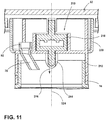
- the prefilling water dispenser 10 can include a fluid level sensor 38 that incorporates a load cell 210 for monitoring a fluid level 40 of the dispensed fluid 42 that is contained within the removable fluid container 18.
- the load cell 210 can be incorporated within a head assembly 212 that receives the removable fluid container 18.
- the various fluid lines 82 can extend into the head assembly 212 for delivering the water 16 through the dedicated fluid port 70 of the shelf spigot 34 into the removable fluid container 18.
- the removable fluid container 18 hangs from the head assembly 212.
- the head assembly 212 includes a gravity portion 214 that engages the load cell 210 that is coupled to the shelf 32.
- the removable fluid container 18 exerts a downward force 216 upon the head assembly 212, which moves vertically with respect to the shelf 32 and load cell 210.
- This downward force 216 is transferred via the gravity portion 214 and into the load cell 210.
- the amount of downward force 216 exerted upon the head assembly 212 also increases.
- This increase in weight of the dispensed fluid 42 within the removable fluid container 18 is transferred into the load cell 210.
- the load cell 210 monitors this downward force 216.
- the load cell 210 is adapted to automatically shut off the valve 136 to prevent an overflow of dispensed fluid 42 within the removable fluid container 18.
- the load cell 210 can be positioned centrally within the head assembly 212.
- the gravity portion 214 places a downward force 216 that compresses a portion of the load cell 210.
- the removable fluid container 18 can be a portable drinking bottle that can be removed from the head assembly 212 for portable use by a user.
- the rotating assembly that is positioned at the top of the removable fluid 18 can be used in connection with the head assembly 212.
- a separate portable adapter can be attached to the top of the removable fluid container 18 for use as a portable drinking bottle.
- This portable drinking bottle can be stored within the refrigerating appliance to cool the water 16 contained therein.
- the removable water bottle 18 can be connected with a head assembly 212 to be automatically filled with water 16.
- the water dispenser 10 can determine an amount of water 16 contained within the removable fluid container 18 at any time.
- the load cell 210 can also operate to measure when the removable fluid container 18 is filled with water 16 to prevent overflow by shutting off the valve 136. Accordingly, the load cell 210 can be attached with a controller 46 for operating the water dispenser 10.
- the load cell 210 can be in the form of a tension cell 218.
- the tension cell 218 operates in connection with the head assembly 212.
- the downward force 216 exerted by the removable fluid container 18 having the water 16 is a pulling force rather than a downward compressive force.
- the tension cell 218 measures an amount of tension represented by the downward force 216 exerted by the removable fluid container 18 having water 16 contained therein.
- the head assembly 212 is attached to the tension cell 18 and pulls a portion of the tension cell 218 downward to measure the downward force 216.
- a cosmetic cover 220 can be positioned around the head assembly 212 for concealing the load cell 210, the tension cell 218, or other similar aspect of the load cell 210.
- the load cell 210 can be incorporated within an aspect of the rail assembly 60.
- the load cell 210 can be coupled with one or both of the sliding rails 64.
- the sliding rails 64 can transfer the downward force 216 that is exerted by the removable fluid container 18 having the water 16 into the load cell 210.
- the load cell 210 can be incorporated within a portion of the shelf 32.
- the load cell 210 can be positioned eccentric to the head assembly 212 and the removable water bottle 18.
- the head assembly 212 can include a moment arm 222 that exerts the downward force 216 onto the load cell 210.
- the moment arm 222 uses the moment arm 222 to exert the downward force 216 along a vertical axis 224 that may be outside of the removable fluid container 18.
- the moment arm 222 uses the moment arm 222 to engages the load cell 210 along this vertical axis 224.
- a torque is typically exerted upon the head assembly 212. This torque results in the downward force 216 being exerted onto the load cell 210 in an angular direction 226.
- the downward force 216 exerted by the removable fluid container 18 onto the head assembly 212 is substantially similar to that exemplified in FIG. 10 .
- the embodiment illustrated in FIG. 12 can include a pair of load cells 210.
- One load cell 210 can be used to measure an amount of water 16 contained within the removable fluid container.
- the other load cell 210 can be used to determine whether the removable fluid container 18 has been properly installed within the head assembly 212.
- a single load cell 210 can be positioned eccentric to the head assembly 212 for engaging the moment arm 222 that extends outward from the head assembly 212.
Landscapes
- Engineering & Computer Science (AREA)
- Physics & Mathematics (AREA)
- Mechanical Engineering (AREA)
- Chemical & Material Sciences (AREA)
- Combustion & Propulsion (AREA)
- Thermal Sciences (AREA)
- General Engineering & Computer Science (AREA)
- Fluid Mechanics (AREA)
- General Physics & Mathematics (AREA)
- Electromagnetism (AREA)
- Devices For Dispensing Beverages (AREA)
Applications Claiming Priority (1)
| Application Number | Priority Date | Filing Date | Title |
|---|---|---|---|
| US16/236,392 US10837698B2 (en) | 2018-12-29 | 2018-12-29 | Water prefilling assembly for use in a refrigerating appliance |
Publications (1)
| Publication Number | Publication Date |
|---|---|
| EP3674637A1 true EP3674637A1 (de) | 2020-07-01 |
Family
ID=68841018
Family Applications (1)
| Application Number | Title | Priority Date | Filing Date |
|---|---|---|---|
| EP19214625.6A Withdrawn EP3674637A1 (de) | 2018-12-29 | 2019-12-09 | Kühlgerät |
Country Status (3)
| Country | Link |
|---|---|
| US (3) | US10837698B2 (de) |
| EP (1) | EP3674637A1 (de) |
| CN (1) | CN111380311A (de) |
Families Citing this family (9)
| Publication number | Priority date | Publication date | Assignee | Title |
|---|---|---|---|---|
| US10948229B2 (en) | 2019-02-12 | 2021-03-16 | Bsh Home Appliances Corporation | Shelf-integrated water dispenser for refrigerator appliance |
| US11118832B2 (en) * | 2019-04-17 | 2021-09-14 | Whirlpool Corporation | Shelf assembly with water dispenser and filtration system |
| US11098948B2 (en) * | 2019-06-04 | 2021-08-24 | Whirlpool Corporation | Water dispensing system |
| KR20210076354A (ko) * | 2019-12-16 | 2021-06-24 | 엘지전자 주식회사 | 냉장고 |
| USD966352S1 (en) * | 2020-04-17 | 2022-10-11 | Samsung Electronics Co., Ltd. | Refrigerator |
| US11772953B2 (en) * | 2020-06-15 | 2023-10-03 | Electrolux Home Products, Inc. | Automatic water dispenser for refrigerator |
| US11326825B2 (en) * | 2020-07-16 | 2022-05-10 | Haier Us Appliance Solutions, Inc. | Stand-alone ice and beverage appliance |
| US11519775B2 (en) * | 2020-12-04 | 2022-12-06 | Haier Us Appliance Solutions, Inc. | Appliance with sensing for load determination |
| US11732960B2 (en) * | 2021-02-11 | 2023-08-22 | Haier Us Appliance Solutions, Inc. | Refrigerator appliance having a weight-detecting shelf assembly |
Citations (4)
| Publication number | Priority date | Publication date | Assignee | Title |
|---|---|---|---|---|
| WO2003046451A1 (en) * | 2001-11-27 | 2003-06-05 | Multibrás S.A. Eletrodomésticos | Water dispensing reservoir for a refrigerator |
| EP1752723A2 (de) * | 2005-08-10 | 2007-02-14 | Whirlpool Corporation | Kühlschrank mit Regal, das als gekühlter Getränkebehälter dient |
| US20070278141A1 (en) * | 2006-05-15 | 2007-12-06 | Ginger Patera | Water filter and dispenser system |
| US20120024003A1 (en) * | 2009-02-02 | 2012-02-02 | Lg Electronics Inc. | Refrigerator |
Family Cites Families (15)
| Publication number | Priority date | Publication date | Assignee | Title |
|---|---|---|---|---|
| US3024621A (en) * | 1960-08-18 | 1962-03-13 | Paul B Parker | Water cooling kit for refrigerators |
| US3250303A (en) * | 1963-09-18 | 1966-05-10 | Kidde & Co Walter | Container guiding and supporting device for container filling apparatus |
| US5309960A (en) * | 1993-05-19 | 1994-05-10 | Boyd Coffee Company | Cup holder for use in a beverage processing machine |
| US6574984B1 (en) | 2002-02-07 | 2003-06-10 | Camco Inc. | Refrigerator door mounted water dispensing assembly |
| AU2005207860A1 (en) | 2004-01-20 | 2005-08-11 | 3M Innovative Properties Company | Water dispenser with water filter for a refrigerator |
| DE102006052448A1 (de) * | 2006-11-07 | 2008-05-08 | BSH Bosch und Siemens Hausgeräte GmbH | Kältegerät mit Kaltwasserspender |
| EP2728282A4 (de) | 2011-08-09 | 2015-04-29 | Dongbu Daewoo Electronics Corp | Kühlschrank |
| KR20130059987A (ko) | 2011-11-29 | 2013-06-07 | 삼성전자주식회사 | 냉장고 |
| US9890029B2 (en) | 2011-12-09 | 2018-02-13 | Electrolux Home Products, Inc. | Refrigerator with automatic liquid dispenser |
| CN105692527B (zh) * | 2013-03-22 | 2018-11-27 | 百事可乐公司 | 容器填充系统和用于容器填充系统的阀 |
| KR101476299B1 (ko) | 2013-04-16 | 2014-12-24 | 엘지전자 주식회사 | 냉장고 |
| US20150197417A1 (en) | 2014-01-16 | 2015-07-16 | Haier America Research And Development Co., Ltd. | Self-filling refrigerator water pitcher |
| KR102237595B1 (ko) * | 2014-08-13 | 2021-04-07 | 삼성전자주식회사 | 냉장고 및 그 제어 방법 |
| US10611621B2 (en) | 2016-05-25 | 2020-04-07 | Steven Gonzales | Space-saving liquid dispensing and filtration container |
| KR20190126635A (ko) * | 2018-05-02 | 2019-11-12 | 주식회사 위니아대우 | 냉장고의 자동물공급장치 |
-
2018
- 2018-12-29 US US16/236,392 patent/US10837698B2/en active Active
-
2019
- 2019-12-03 CN CN201911223209.3A patent/CN111380311A/zh active Pending
- 2019-12-09 EP EP19214625.6A patent/EP3674637A1/de not_active Withdrawn
-
2020
- 2020-10-14 US US17/070,106 patent/US11668516B2/en active Active
-
2023
- 2023-04-14 US US18/300,725 patent/US20230251029A1/en active Pending
Patent Citations (4)
| Publication number | Priority date | Publication date | Assignee | Title |
|---|---|---|---|---|
| WO2003046451A1 (en) * | 2001-11-27 | 2003-06-05 | Multibrás S.A. Eletrodomésticos | Water dispensing reservoir for a refrigerator |
| EP1752723A2 (de) * | 2005-08-10 | 2007-02-14 | Whirlpool Corporation | Kühlschrank mit Regal, das als gekühlter Getränkebehälter dient |
| US20070278141A1 (en) * | 2006-05-15 | 2007-12-06 | Ginger Patera | Water filter and dispenser system |
| US20120024003A1 (en) * | 2009-02-02 | 2012-02-02 | Lg Electronics Inc. | Refrigerator |
Also Published As
| Publication number | Publication date |
|---|---|
| US20210025648A1 (en) | 2021-01-28 |
| US10837698B2 (en) | 2020-11-17 |
| US20200208904A1 (en) | 2020-07-02 |
| CN111380311A (zh) | 2020-07-07 |
| US11668516B2 (en) | 2023-06-06 |
| US20230251029A1 (en) | 2023-08-10 |
Similar Documents
| Publication | Publication Date | Title |
|---|---|---|
| EP3674637A1 (de) | Kühlgerät | |
| US11821680B2 (en) | Refrigerator and method of controlling the same | |
| US10677513B2 (en) | Refrigeration appliance with an ice/water dispenser | |
| US5819547A (en) | Refrigerator having a water dispensing system in which a water reservoir is automatically refilled when its water level is low | |
| US9352952B2 (en) | Fluid portion dispenser | |
| BR0316813B1 (pt) | aparelho de dispensa de bebida alcoólica. | |
| MX2009001922A (es) | Maquina dispensadora de cubierta helada. | |
| KR20130113920A (ko) | 유체 전달 시스템 | |
| EP1100721B9 (de) | Vorrichtung zum Abgeben von Flüssigkeit aus nebeneinander angeordneten Behältern | |
| JP2019142592A (ja) | 飲料サーバ | |
| US11820642B2 (en) | System for dispensing liquid from inverted container | |
| WO2021184709A1 (zh) | 自动供水装置及具有其的冰箱 | |
| KR102127173B1 (ko) | 냉장고의 제빙용 급수장치 | |
| WO2021239778A1 (en) | Fluid dispensing apparatus | |
| JPH0979743A (ja) | 冷却飲料供給装置 | |
| PH22020000319U1 (en) | Automatic hand sanitizer dispenser | |
| NZ619582B2 (en) | Fluid portion dispenser |
Legal Events
| Date | Code | Title | Description |
|---|---|---|---|
| PUAI | Public reference made under article 153(3) epc to a published international application that has entered the european phase |
Free format text: ORIGINAL CODE: 0009012 |
|
| STAA | Information on the status of an ep patent application or granted ep patent |
Free format text: STATUS: THE APPLICATION HAS BEEN PUBLISHED |
|
| AK | Designated contracting states |
Kind code of ref document: A1 Designated state(s): AL AT BE BG CH CY CZ DE DK EE ES FI FR GB GR HR HU IE IS IT LI LT LU LV MC MK MT NL NO PL PT RO RS SE SI SK SM TR |
|
| AX | Request for extension of the european patent |
Extension state: BA ME |
|
| STAA | Information on the status of an ep patent application or granted ep patent |
Free format text: STATUS: REQUEST FOR EXAMINATION WAS MADE |
|
| 17P | Request for examination filed |
Effective date: 20201221 |
|
| RBV | Designated contracting states (corrected) |
Designated state(s): AL AT BE BG CH CY CZ DE DK EE ES FI FR GB GR HR HU IE IS IT LI LT LU LV MC MK MT NL NO PL PT RO RS SE SI SK SM TR |
|
| STAA | Information on the status of an ep patent application or granted ep patent |
Free format text: STATUS: EXAMINATION IS IN PROGRESS |
|
| 17Q | First examination report despatched |
Effective date: 20210329 |
|
| STAA | Information on the status of an ep patent application or granted ep patent |
Free format text: STATUS: THE APPLICATION HAS BEEN WITHDRAWN |
|
| 18W | Application withdrawn |
Effective date: 20210802 |