EP3674569B1 - Verbindungsbefestigungselement - Google Patents
Verbindungsbefestigungselement Download PDFInfo
- Publication number
- EP3674569B1 EP3674569B1 EP19219761.4A EP19219761A EP3674569B1 EP 3674569 B1 EP3674569 B1 EP 3674569B1 EP 19219761 A EP19219761 A EP 19219761A EP 3674569 B1 EP3674569 B1 EP 3674569B1
- Authority
- EP
- European Patent Office
- Prior art keywords
- fastener
- sleeve
- toe side
- side holding
- shape
- Prior art date
- Legal status (The legal status is an assumption and is not a legal conclusion. Google has not performed a legal analysis and makes no representation as to the accuracy of the status listed.)
- Active
Links
Images


Classifications
-
- F—MECHANICAL ENGINEERING; LIGHTING; HEATING; WEAPONS; BLASTING
- F16—ENGINEERING ELEMENTS AND UNITS; GENERAL MEASURES FOR PRODUCING AND MAINTAINING EFFECTIVE FUNCTIONING OF MACHINES OR INSTALLATIONS; THERMAL INSULATION IN GENERAL
- F16B—DEVICES FOR FASTENING OR SECURING CONSTRUCTIONAL ELEMENTS OR MACHINE PARTS TOGETHER, e.g. NAILS, BOLTS, CIRCLIPS, CLAMPS, CLIPS OR WEDGES; JOINTS OR JOINTING
- F16B15/00—Nails; Staples
- F16B15/08—Nails; Staples formed in integral series but easily separable
-
- B—PERFORMING OPERATIONS; TRANSPORTING
- B25—HAND TOOLS; PORTABLE POWER-DRIVEN TOOLS; MANIPULATORS
- B25C—HAND-HELD NAILING OR STAPLING TOOLS; MANUALLY OPERATED PORTABLE STAPLING TOOLS
- B25C3/00—Portable devices for holding and guiding nails; Nail dispensers
-
- F—MECHANICAL ENGINEERING; LIGHTING; HEATING; WEAPONS; BLASTING
- F16—ENGINEERING ELEMENTS AND UNITS; GENERAL MEASURES FOR PRODUCING AND MAINTAINING EFFECTIVE FUNCTIONING OF MACHINES OR INSTALLATIONS; THERMAL INSULATION IN GENERAL
- F16B—DEVICES FOR FASTENING OR SECURING CONSTRUCTIONAL ELEMENTS OR MACHINE PARTS TOGETHER, e.g. NAILS, BOLTS, CIRCLIPS, CLAMPS, CLIPS OR WEDGES; JOINTS OR JOINTING
- F16B43/00—Washers or equivalent devices; Other devices for supporting bolt-heads or nuts
Definitions
- the present invention relates to a connection fastener in which a plurality of fasteners for a driving tool are connected.
- the document US 4 106 618 A discloses a nail clip with nails and sleeves, wherein the sleeves show a gap between sleeve and nail at the lower and upper end.
- connection fastener in which a plurality of fasteners are connected by a connection band can be used for various types of driving tools because a large number of fasteners can be set together in a driving tool and continuously injected.
- connection band of such a connection fastener is generally provided with a detachable sleeve as described in Japanese Patent No. 4966971 , for example, and holds the fastener with the sleeves one by one.
- the inner surface of the sleeve of the connection band is formed in a cylindrical shape to hold the inserted fastener. Also, the outer shape of the sleeve is formed so as to be along the inside of the injection path so that the posture of the fastener can be kept vertical in the injection path when ejecting the fastener.
- the inventors have found that, when a connection fastener of the related art as described above is used, the pulling-out strength may be lowered when a fastener is driven into a thin steel plate or the like. That is, when the fastener penetrates into a thin steel plate or the like, a burring shape is formed around it. This burring shape tries to grow as the fastener penetrates, but when the fastener penetrates to a certain extent, the connection band attached to the fastener abuts on the projecting tip of the burring shape and acts to press down the burring shape. When the burring shape is pressed down and crushed or spread, the burring shape is formed without adhering to the fastener, and thus the holding power of the fastener is reduced.
- the invention is a fastener and sleeve as defined by claim 1.
- An aspect of the invention is based on the above discovery and an object thereof is to provide a connection fastener which can prevent a reduction in the pulling-out strength of a fastener when the fastener is driven into a thin steel plate or the like.
- An embodiment of the present invention relates to a connection fastener in which a plurality of fasteners for a driving tool are connected, which includes:
- the invention is as defined in claim 1 and a gap is formed between the sleeve and the fastener so as to face the toe side of the fastener.
- the shape of the sleeve of the related art can be used as it is, it does not affect the function of stabilizing the posture of the fastener in the injection path or the magazine. Therefore, it is possible to improve only the pulling-out strength of the fastener without deteriorating other functions due to the connection band and without changing the shape of the magazine and the injection path.
- the gap is formed by forming a recess portion on an inner peripheral surface of the sleeve.
- the recess portion may be formed in a cylindrical shape so as to surround a periphery of the fastener. With this configuration, the sleeve is easily crushed into a circular shape when the fastener is driven. When the sleeve is crushed into a circular shape, the sleeve acts as a washer, so it is possible to increase the holding power by the fastener.
- the recess portion may have a tapered shape which gradually expands as it extends toward the toe side.
- an inner peripheral surface of an end portion opposite to an end portion where the gap is formed is in close contact with the fastener.
- the sleeve may be formed asymmetrically in a vertical direction. With this configuration, the loading direction when loading the connection fastener to the magazine is determined, so it can prevent the wrong mounting from being made upside down.
- a connection fastener 10 is formed by connecting a plurality of fasteners 11 for a driving tool 30.
- the connection fastener 10 includes the fastener 11 and a connection band 20.
- the fastener 11 is a pin provided with a head portion 12.
- the fastener 11 includes a shaft portion 13 having a substantially cylindrical shape further on the toe side than the head portion 12 and includes a tip end portion 15 having a substantially conical shape (cannonball shape) further on the toe side than the shaft portion 13.
- connection band 20 is a member made of synthetic resin to which sleeves 21 that hold the fasteners 11 one by one are connected.
- the sleeve 21 is formed with an insertion hole 25 penetrating vertically.
- the inner peripheral surface of the insertion hole 25 is formed with an inner diameter along the shaft portion 13 of the fastener 11. For this reason, when the fastener 11 is inserted through the sleeve 21, the inner surface of the insertion hole 25 is brought into close contact with the shaft portion 13 of the fastener 11 so that the fastener 11 is firmly held.
- the sleeves 21 holding the fasteners 11 one by one are connected to each other by a connection portion 28 so as to be able to be separated as illustrated in Figs. 1A and 1B .
- the sleeves 21 are connected horizontally in a straight line shape with the height of the head portions 12 aligned.
- the connection portion 28 for connecting the sleeve 21 is designed to be broken when the fastener 11 is driven. When the connection portion 28 is broken, the sleeve 21 is cut from the connection band 20 and is driven into a driving target material 40 together with the fastener 11.
- the sleeve 21 includes a head portion side holding portion 22 provided on the head portion 12 side of the fastener 11, a toe side holding portion 23 provided on the toe side of the fastener 11, and a constricted portion 24 provided between the head portion side holding portion 22 and the toe side holding portion 23.
- the toe side holding portion 23 is formed so that the length of the outer periphery thereof is longer than that of the head portion side holding portion 22.
- the outer periphery of the toe side holding portion 23 is formed in a circular shape having a diameter substantially equal to the inner diameter of an injection path 35a (described below).
- the outer periphery of the head portion side holding portion 22 is formed such that the lateral width of the head portion side holding portion 22 is smaller than the lateral width of the toe side holding portion 23.
- the head portion side holding portion 22 and the toe side holding portion 23 according to the embodiment are formed in different shapes and the sleeve 21 is formed asymmetrically in a vertical direction.
- connection portions 28 described above are provided at two locations above and below corresponding to the head portion side holding portion 22 and the toe side holding portion 23, respectively. That is, the adjacent head portion side holding portions 22 are connected by the connection portion 28 and the adjacent toe side holding portions 23 are connected by the connection portion 28.
- constricted portion 24 is formed so that the length of the outer circumference is shorter than that of the head portion side holding portion 22 and the toe side holding portion 23.
- an intermediate portion has a shape that is recessed inward so that the intermediate portion becomes the thinnest.
- the constricted portion 24 is formed with an opening 24a which exposes a side surface of the shaft portion 13 of the fastener 11.
- the shaft portion 13 of the fastener 11 can be held in a long upper and lower range.
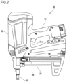
- the driving tool 30 which uses the connection fastener 10 may be anything as long as it ejects the fastener 11, but may be of any configuration as illustrated in Fig. 2 , for example.
- the driving tool 30 illustrated in Fig. 2 includes an output unit 32 which accommodates a drive mechanism 33 therein, and a grip 31 and a magazine 37 which are connected so as to be orthogonal to the output unit 32.
- a nose portion 35 which is pressed against the driving target material 40 is provided at the tip of the output unit 32 and the leading fastener 11 loaded in the magazine 37 is supplied to the nose portion 35 by a pusher 38.
- the fastener 11 supplied to the nose portion 35 is ejected from an injection port provided at the tip of the nose portion 35 by a driver 34.
- the nose portion 35 is provided so as to be slidable with respect to the housing and is always urged in a protruding direction by a spring.
- the nose portion 35 is pressed against the driving target material 40 and is slid.
- the operation of a trigger 31a described below becomes effective because the nose portion 35 is pushed. In other words, the driving operation is not performed when the nose portion 35 is not slid.
- the injection path 35a for guiding the fastener 11 to the injection port is formed inside the nose portion 35.
- the leading fastener 11 of the connection fastener 10 passes through the injection path 35a and is ejected from the tip (injection port) of the injection path 35a.
- the driver 34 capable of reciprocating in the injection path 35a in order to eject the fastener 11, the drive mechanism 33 for operating the driver 34, and the like are arranged.
- a known power source may be used for the drive mechanism 33.
- the known drive mechanism 33 such as a spring drive type, a compressed air type, or a gas combustion type may be used.
- the magazine 37 is used for loading the connection fastener 10.
- the magazine 37 is connected to the vicinity of the tip of the output unit 32. Inside the magazine 37 is provided with the pusher 38 for pressing the connection fastener 10 loaded in the magazine 37 in a direction of the injection path 35a.
- the pusher 38 is always biased forward by a spring and the connection fastener 10 loaded in the magazine 37 is always pressed forward by the pusher 38.
- the grip 31 is a part for an operator who uses the driving tool 30 to grip.
- the grip 31 is formed in a rod shape so that an operator can easily grasp it.
- the trigger 31a which can be pulled with an index finger is provided at a position where the index finger of an operator is applied when the operator grips the grip 31.
- the trigger switch arranged inside the grip 31 is turned on and an operation signal is output to a control device.
- the control device activates the drive mechanism 33 using this operation signal as a trigger.
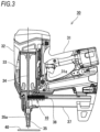
- connection fastener 10 In a state before driving with the driving tool 30, as illustrated in Fig. 3 , the connection fastener 10 is pressed forward by the pusher 38 and the leading fastener 11 of the connection fastener 10 waits directly under the driver 34.
- driving can be performed.
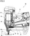
- the drive mechanism 33 When the trigger 31a is operated in the state of Fig. 4 , the drive mechanism 33 is operated to drive out the driver 34 as illustrated in Fig. 5 .
- the driver 34 hits the head portion 12 of the fastener 11 at the head of the connection fastener 10 and drives out the fastener 11 in the direction of the driving target material 40 through the injection path 35a.
- the sleeve 21 holding the leading fastener 11 is cut off from the connection fastener 10 and driven out in the direction of the driving target material 40 together with the leading fastener 11.
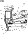
- the fastener 11 penetrates into the driving target material 40 as illustrated in Fig. 6 .
- the sleeve 21 holding the fastener 11 is crushed into a circular shape and is interposed between the head portion 12 of the fastener 11 and the driving target material 40.
- the sleeve 21 may be torn apart from the fastener 11 due to the pressure at the time of driving, but there is no problem even when the sleeve 21 is detached from the fastener 11.
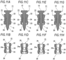
- a recess portion 26 as illustrated in Figs. 8A to 8E is formed.
- the recess portion 26 is formed in an opening edge of the toe side of the insertion hole 25 and the recess portion 26 is a groove recessed from the bottom surface (surface of the toe side) of the sleeve 21 in an axial direction of the fastener 11.
- the recess portion 26 of a cylindrical shape is formed so as to surround the fastener 11.
- the recess portion 26 includes a tapered portion 26a and a large-diameter portion 26b which continues to the toe side of the tapered portion 26a.
- the tapered portion 26a has a frusto-conical inner peripheral surface and has a tapered shape which gradually expands as it extends toward the toe side.
- the large-diameter portion 26b has a cylindrical inner peripheral surface and is formed with the same diameter as that of the toe side of the tapered portion 26a.
- the recess portion 26 is used for forming a burring shape 41 in close contact with the fastener 11 when the fastener 11 is driven into the driving target material 40 such as a thin steel plate. That is, as illustrated in Figs. 9A to 9F , when the fastener 11 penetrates into the driving target material 40 such as a thin steel plate, the burring shape 41 is formed around it. The burring shape 41 grows as the fastener 11 penetrates. When the fastener 11 penetrates to a certain extent, the sleeve 21 attached to the fastener 11 abuts on the driving target material 40. However, the gap G is formed by the recess portion 26 around the fastener 11, and thus the sleeve 21 does not hinder the formation of the burring shape 41. In other words, the burring shape 41 is formed in close contact with the fastener 11 by entering the gap G. For this reason, it is possible to improve the pulling-out strength of the driven fastener 11.
- the sleeve 21 has the gap G formed only on the toe side and the inner peripheral surface of the end portion (head portion 12 side) opposite to the end portion where the gap G is formed is in close contact with the fastener 11. In this way, by forming the gap G only on the toe side, the inclination of the fastener 11 in the injection path 35a can be suppressed.
- the upper and lower ranges in which the shaft portion 13 of the fastener 11 can be held become longer, and thus the inclination of the fastener 11 can be suppressed in the injection path 35a. That is, the amount of inclination S2 (see Fig. 10F ) of the fastener 11 when the gap G is not formed on the head portion 12 side is smaller than the amount of inclination S1 (see fig. 10C ) of the fastener 11 when the gap G is formed on the head portion 12 side. Therefore, when no gap G is formed on the head portion 12 side, the fastener 11 can be driven straight out.
- the gap G is formed between the sleeve 21 and the fastener 11 so as to face the toe side of the fastener 11.
- the burring shape 41 is formed so as to enter the gap G. Therefore, the growth of the burring shape 41 is not hindered. Therefore, since the burring shape 41 is formed in close contact with the fastener 11, the pulling-out strength of the driven fastener 11 does not decrease (in other words, the pulling-out strength of the fastener 11 is improved as compared with a case of the related art).
- the shape (see Figs. 14A and 14B ) of the related art can be used as it is for the outer shape of sleeve 21, there is no effect on the function of stabilizing the posture of the fastener 11 in the injection path 35a or the magazine 37. Therefore, it is possible to improve only the pulling-out strength of the fastener 11 without deteriorating other functions of the connection band 20 and without changing the shapes of the magazine 37 and the injection path 35a.
- the gap G is formed by forming the recess portion 26 on the inner peripheral surface of the sleeve 21. For this reason, when the fastener 11 is driven and the sleeve 21 is crushed, the toe side of the sleeve 21 is likely to spread outward, and thus the crushing load is reduced. By making the sleeve 21 easy to be crushed in this way, the impact at the time of driving is absorbed and deformation of the driving target material 40 such as a thin steel plate is suppressed. Therefore, the deformation of the burring shape 41 is suppressed, and thus the adhesion degree between the fastener 11 and the burring shape 41 can be increased.
- the recess portion 26 is formed in a cylindrical shape so as to surround the periphery of the fastener 11. By configuring in this way, the sleeve 21 is easily crushed into a circular shape when the fastener 11 is driven. Since the sleeve 21 is crushed into a circular shape, the sleeve 21 serves as a washer, and thus the holding force by the fastener 11 can be increased.
- the recess portion 26 has a tapered shape (tapered portion 26a) which gradually expands as it extends toward the toe side.
- the inner peripheral surface of the end portion opposite to the end portion where the gap G is formed is in close contact with the fastener 11.
- the sleeve 21 is formed asymmetric in the vertical direction. Therefore, since the loading direction when loading the connection fastener 10 into the magazine 37 is determined, it is possible to prevent the wrong mounting from being made upside down.
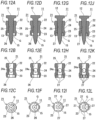
- the shape of the recess portion 26 according to the embodiment described above is merely an example. Since the recess portion 26 may have various shapes, the recess portion 26 having a different shape may be provided instead of the recess portion 26 according to the embodiment described above.
- the recess portion 26 formed only with a tapered shape which gradually expands as it extends toward the toe side may be provided.
- the recess portion 26 may be formed in the shape of a stepped hole continuous to the insertion hole 25 and the inner diameter of the recess portion 26 may be larger than the outer diameter of the fastener 11.
- the recess portion 26 may be formed in a stepped hole shape continuous to the insertion hole 25 and the inner diameter of the recess portion 26 may be larger than the outer diameter of the fastener 11, and further the inner peripheral surface of the recess portion 26 may have a tapered shape which gradually expands as it extends toward the toe side.
- a bowl-shaped recess portion 26 which gradually bulges outward as it extends to the toe side may be provided.
- the recess portion 26 having a polygonal shape instead of a circular cross section may be provided.
- the recess portion 26 having a hexagonal cross section may be provided, or as illustrated in Figs. 12D, 12E, and 12F , the recess portion 26 having an octagonal cross section may be provided.
- a plurality of leg portions 27 protruding toward the toe side of the fastener 11 may be provided on the sleeve 21, thereby forming the gap G.
- the four leg portions 27 may be provided so as to surround the periphery of the fastener 11 and the gap G may be formed between the leg portions 27 and the fastener 11.
- the eight leg portions 27 may be provided so as to surround the periphery of the fastener 11 and the gap G may be formed between the leg portions 27 and the fastener 11.
- the arrangement and shape of the leg portions 27 are not limited to the above example and can be changed as appropriate.
- the shapes of the plurality of leg portions 27 may not be the same and the leg portions 27 having different shapes may be provided in combination.
- the load (deformation load of the sleeve 21) at the time of driving may be reduced by setting the interval of the adjacent leg portions 27 wide.
- the number of the leg portions 27 can also be freely changed. However, in order to sufficiently obtain the effect of maintaining the vertical posture of the fastener 11, it is preferable to provide three or more leg portions 27 around the periphery.
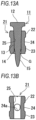
- the diameter of the fastener 11 may be changed to thereby form the gap G, which is, however, not in the scope of claim 1.
- a reduced diameter portion 14 may be provided in a portion of the fastener 11 where the sleeve 21 is attached and the gap G may be formed between the reduced diameter portion 14 and the sleeve 21.
- the fastener 11 provided with such the reduced diameter portion 14 and the sleeve 21 formed with the recess portion 26 may be combined to form the gap G.
Landscapes
- Engineering & Computer Science (AREA)
- General Engineering & Computer Science (AREA)
- Mechanical Engineering (AREA)
- Portable Nailing Machines And Staplers (AREA)
- Insertion Pins And Rivets (AREA)
- Details Of Spanners, Wrenches, And Screw Drivers And Accessories (AREA)
Claims (9)
- Ein Befestigungselement und eine Hülse umfassend:ein Befestigungselement (11) für ein Antriebswerkzeug (30); undeine Hülse (21), die das Befestigungselement (11) hält, wobeiein Spalt (G) zwischen der Hülse (21) und dem Befestigungselement (11) so gebildet wird, dass er einer Vorderseite des Befestigungselements zugewandt ist, indem ein Vertiefungsabschnitt (26) an einer inneren Umfangsfläche der Hülse (21) gebildet wird, undin der Hülse (21) eine innere Umfangsfläche eines Endabschnitts, der einem Endabschnitt gegenüberliegt, an dem der Spalt (G) ausgebildet ist, in engem Kontakt mit dem Befestigungselement (11) steht,ein Innendurchmesser des Vertiefungsabschnitts (26) an der Fußseite des Befestigungselements (11) größer ist als der Innendurchmesser der Hülse (21) an einem Zwischenabschnitt,wobei
die Hülse (21) umfasst:einen kopfteilseitigen Halteabschnitt (22), der an einer Kopfteilseite des Befestigungselements (11) vorgesehen ist;einen spitzenseitigen Halteabschnitt (23), der an der Spitzenseite des Befestigungselements (11) vorgesehen ist; undeinen eingeschnürten Abschnitt (24), der zwischen dem kopfteilseitigen Abschnitt (22) und dem spitzenseitigen Halteabschnitt (23) vorgesehen ist. - Befestigungselement und Hülse nach Anspruch 1, wobei
der Vertiefungsabschnitt (26) in einer zylindrischen Form ausgebildet ist, um einen Umfang des Befestigungselements (11) zu umgeben. - Befestigungselement und Hülse nach Anspruch 1 oder 2, wobei
der Vertiefungsabschnitt (26) eine sich verjüngende Form aufweist, die sich allmählich in Richtung der Spitzenseite ausdehnt. - Befestigungselement und Hülse nach einem der Ansprüche 1 bis 3, wobei die Hülse (21) in vertikaler Richtung asymmetrisch ausgebildet ist.
- Befestigungselement und Hülse nach Anspruch 1, wobei
der spitzenseitige Halteabschnitt (23) so geformt ist, daß die Länge des Außenumfangs des spitzenseitigen Halteabschnitts länger ist als die des kopfteilseitigen Halteabschnitts (22). - Befestigungselement und Hülse nach Anspruch 1 oder 2, wobei
wenn die Hülse (21) von vorne betrachtet wird, der äußere Umfang des kopfteilseitigen Halteabschnitts (22) so ausgebildet ist, dass die seitliche Breite des kopfteilseitigen Halteabschnitts (22) kleiner ist als die seitliche Breite des spitzenseitigen Halteabschnitts. - Befestigungselement und Hülse nach einem der Ansprüche 1 bis 3, wobei
der kopfteilseitige Halteabschnitt (22) und der spitzenseitige Halteabschnitt (23) unterschiedlich geformt sind und die Hülse (21) in vertikaler Richtung asymmetrisch ausgebildet ist. - Befestigungselement und Hülse nach einem der Ansprüche 1 bis 4, wobei bei Betrachtung der Hülse (21) von vorne ein Zwischenabschnitt eine nach innen vertiefte Form aufweist, so dass der Zwischenabschnitt am dünnsten wird.
- Befestigungselement und Hülse nach einem der Ansprüche 1 bis 5, wobei der eingeschnürte Abschnitt (24) mit einer Öffnung (24a) ausgebildet ist, die eine seitliche Oberfläche des Abschnitts (13) der Welle des Befestigungselements (11) freilegt.
Applications Claiming Priority (1)
| Application Number | Priority Date | Filing Date | Title |
|---|---|---|---|
| JP2018244824A JP7192491B2 (ja) | 2018-12-27 | 2018-12-27 | 連結ファスナー |
Publications (3)
| Publication Number | Publication Date |
|---|---|
| EP3674569A1 EP3674569A1 (de) | 2020-07-01 |
| EP3674569B1 true EP3674569B1 (de) | 2025-05-21 |
| EP3674569C0 EP3674569C0 (de) | 2025-05-21 |
Family
ID=69055703
Family Applications (1)
| Application Number | Title | Priority Date | Filing Date |
|---|---|---|---|
| EP19219761.4A Active EP3674569B1 (de) | 2018-12-27 | 2019-12-27 | Verbindungsbefestigungselement |
Country Status (8)
| Country | Link |
|---|---|
| US (1) | US11624391B2 (de) |
| EP (1) | EP3674569B1 (de) |
| JP (1) | JP7192491B2 (de) |
| KR (2) | KR20200081301A (de) |
| CN (1) | CN111412209B (de) |
| ES (1) | ES3033292T3 (de) |
| PL (1) | PL3674569T3 (de) |
| TW (1) | TWI837262B (de) |
Citations (1)
| Publication number | Priority date | Publication date | Assignee | Title |
|---|---|---|---|---|
| EP3269987A1 (de) * | 2016-07-15 | 2018-01-17 | Max Co., Ltd. | Verbindungsbefestigungselement |
Family Cites Families (30)
| Publication number | Priority date | Publication date | Assignee | Title |
|---|---|---|---|---|
| DE1478783C3 (de) | 1963-09-17 | 1974-05-16 | Anstalt Fuer Montage-Technik, Vaduz | Verankerungsstift mit einem Scherring |
| US4167229A (en) | 1975-03-22 | 1979-09-11 | Karl M. Reich Maschinenfabrik Gmbh | Screw strip and method for forming the same |
| DE2512825A1 (de) * | 1975-03-22 | 1976-09-30 | Reich Maschf Gmbh Karl | Schraubenstreifen und verfahren zu dessen herstellung |
| US4106618A (en) * | 1975-12-15 | 1978-08-15 | Haytayan Harry M | Nail assemblies |
| JPS571908A (en) | 1980-06-05 | 1982-01-07 | Yokogawa Hokushin Electric Corp | Measuring method of distance |
| DE3606901A1 (de) * | 1986-03-03 | 1987-09-10 | Hilti Ag | Nagelstreifen |
| DE3917846A1 (de) | 1989-06-01 | 1990-12-06 | Hilti Ag | Traegerstreifen fuer pulverkraftbetriebene setzgeraete |
| US5069340A (en) * | 1991-03-05 | 1991-12-03 | Illinois Tool Works Inc. | Strip of collated fasteners for fastener-driving tool |
| DE19602789A1 (de) | 1996-01-26 | 1997-07-31 | Hilti Ag | Nagelstreifen für Setzgerät |
| US5836732A (en) * | 1997-10-07 | 1998-11-17 | Illinois Tool Works, Inc. | Fastener assembly |
| US5931622A (en) * | 1997-10-07 | 1999-08-03 | Illinois Tool Works Inc. | Fastener assembly with lateral end extension |
| DE19831371A1 (de) * | 1998-07-13 | 2000-01-20 | Hilti Ag | Nagelmagazin |
| CN1117222C (zh) * | 1998-10-07 | 2003-08-06 | 伊利诺伊工具公司 | 带有横向端头伸出部的紧固件组件 |
| JP3939089B2 (ja) * | 2000-11-09 | 2007-06-27 | 日本パワーファスニング株式会社 | 連結ファスナー及びこれに使用する連結具 |
| US6814231B2 (en) * | 2002-01-23 | 2004-11-09 | Illinois Tool Works Inc. | Strip of collated fasteners for fastener-driving tool |
| US20040118720A1 (en) * | 2002-12-18 | 2004-06-24 | Powers Fasteners, Inc. | Fastener carrier assembly and method of use |
| US7021462B2 (en) * | 2002-12-18 | 2006-04-04 | Powers Fasteners, Inc. | Fastener carrier assembly and method of use |
| EP1793130B1 (de) * | 2004-06-24 | 2008-08-20 | S.A. Compañía Neumática de Calvado | Band zum fördern von nägeln oder anderen befestigungselementen |
| US20070074880A1 (en) | 2005-09-20 | 2007-04-05 | Paul Gaudron | Carrier strip system and method for different diameter fasteners |
| US7735577B2 (en) | 2005-09-20 | 2010-06-15 | Power Products Iii, Llc | Carrier strip system and method for different diameter fasteners |
| US8360703B2 (en) * | 2006-05-12 | 2013-01-29 | Illinois Tool Works Inc. | Debris-free plastic collating strip for nails |
| TW201024552A (en) * | 2008-10-30 | 2010-07-01 | Powers Products Iii Llc | Carrier strip system and method for different diameter fasteners |
| DE102009001790B4 (de) * | 2009-03-24 | 2014-01-16 | Hilti Aktiengesellschaft | Befestigungselemente-Magazinstreifen |
| GB0915371D0 (en) * | 2009-09-04 | 2009-10-07 | Black & Decker Inc | Fastener assembly |
| US20110068029A1 (en) * | 2009-09-18 | 2011-03-24 | Teng Tino S | Nail-belt for nail gun |
| US8556073B2 (en) * | 2010-11-02 | 2013-10-15 | Jaaco Corporation | Carriers for carrying fasteners for fastener driving tools |
| TWI706836B (zh) | 2013-07-04 | 2020-10-11 | 日商美克司股份有限公司 | 扣件敲擊工具 |
| JP6244695B2 (ja) * | 2013-07-04 | 2017-12-13 | マックス株式会社 | ファスナー打ち込み工具 |
| JP6264788B2 (ja) * | 2013-09-05 | 2018-01-24 | マックス株式会社 | ファスナーの連結構造 |
| JP6897302B2 (ja) | 2016-07-15 | 2021-06-30 | マックス株式会社 | 連結ファスナー |
-
2018
- 2018-12-27 JP JP2018244824A patent/JP7192491B2/ja active Active
-
2019
- 2019-12-25 TW TW108147554A patent/TWI837262B/zh active
- 2019-12-25 CN CN201911353648.6A patent/CN111412209B/zh active Active
- 2019-12-26 KR KR1020190175021A patent/KR20200081301A/ko not_active Ceased
- 2019-12-27 ES ES19219761T patent/ES3033292T3/es active Active
- 2019-12-27 US US16/728,085 patent/US11624391B2/en active Active
- 2019-12-27 PL PL19219761.4T patent/PL3674569T3/pl unknown
- 2019-12-27 EP EP19219761.4A patent/EP3674569B1/de active Active
-
2025
- 2025-06-26 KR KR1020250085271A patent/KR20250100610A/ko active Pending
Patent Citations (1)
| Publication number | Priority date | Publication date | Assignee | Title |
|---|---|---|---|---|
| EP3269987A1 (de) * | 2016-07-15 | 2018-01-17 | Max Co., Ltd. | Verbindungsbefestigungselement |
Also Published As
| Publication number | Publication date |
|---|---|
| JP2020106082A (ja) | 2020-07-09 |
| CN111412209B (zh) | 2023-03-14 |
| ES3033292T3 (en) | 2025-08-01 |
| US20200208668A1 (en) | 2020-07-02 |
| EP3674569A1 (de) | 2020-07-01 |
| JP7192491B2 (ja) | 2022-12-20 |
| US11624391B2 (en) | 2023-04-11 |
| TW202035886A (zh) | 2020-10-01 |
| PL3674569T3 (pl) | 2025-09-22 |
| KR20200081301A (ko) | 2020-07-07 |
| CN111412209A (zh) | 2020-07-14 |
| KR20250100610A (ko) | 2025-07-03 |
| EP3674569C0 (de) | 2025-05-21 |
| TWI837262B (zh) | 2024-04-01 |
Similar Documents
| Publication | Publication Date | Title |
|---|---|---|
| US6779959B1 (en) | Belt of nails for nailers | |
| US4832245A (en) | Automatic nailing apparatus with improved percussion rod and nosepiece | |
| CN102493990B (zh) | 连接的紧固件组件 | |
| US7815086B2 (en) | Nailing machine | |
| EP2103387A1 (de) | Elektrowerkzeug und dämpfungsmechanismus dafür | |
| US6193126B1 (en) | Nose assembly for a nail ejection gun | |
| JP2020089934A (ja) | 打込み工具 | |
| EP3674569B1 (de) | Verbindungsbefestigungselement | |
| TWI636856B (zh) | Fastener tapping tool | |
| JP2004074403A (ja) | ファスナ打込み工具用安定化マガジンフォロア | |
| US20080019798A1 (en) | Nail with a reinforcement section | |
| CN101440836B (zh) | 连接的紧固件组件 | |
| JP2025123522A (ja) | 打込み工具 | |
| US10428853B2 (en) | Connection fastener | |
| EP1623798B1 (de) | Nagelmaschine | |
| JP6244695B2 (ja) | ファスナー打ち込み工具 | |
| US20080128468A1 (en) | Magazine assembly for long and short nails | |
| JP6638259B2 (ja) | 打込み工具 | |
| US11149773B2 (en) | Connection fastener | |
| JP2005349541A (ja) | 釘打機の射出部及びその製造方法 | |
| JP3147209U (ja) | スクリューリング釘およびその連結体 | |
| JP5280181B2 (ja) | 打ち込み工具 | |
| JP6380740B2 (ja) | ファスナー打ち込み工具 | |
| US20130259605A1 (en) | Washer device for fastener driver | |
| JP2006123064A (ja) | 釘打機のマガジンにおける釘ガイド機構 |
Legal Events
| Date | Code | Title | Description |
|---|---|---|---|
| PUAI | Public reference made under article 153(3) epc to a published international application that has entered the european phase |
Free format text: ORIGINAL CODE: 0009012 |
|
| STAA | Information on the status of an ep patent application or granted ep patent |
Free format text: STATUS: THE APPLICATION HAS BEEN PUBLISHED |
|
| AK | Designated contracting states |
Kind code of ref document: A1 Designated state(s): AL AT BE BG CH CY CZ DE DK EE ES FI FR GB GR HR HU IE IS IT LI LT LU LV MC MK MT NL NO PL PT RO RS SE SI SK SM TR |
|
| AX | Request for extension of the european patent |
Extension state: BA ME |
|
| STAA | Information on the status of an ep patent application or granted ep patent |
Free format text: STATUS: REQUEST FOR EXAMINATION WAS MADE |
|
| 17P | Request for examination filed |
Effective date: 20201223 |
|
| RBV | Designated contracting states (corrected) |
Designated state(s): AL AT BE BG CH CY CZ DE DK EE ES FI FR GB GR HR HU IE IS IT LI LT LU LV MC MK MT NL NO PL PT RO RS SE SI SK SM TR |
|
| STAA | Information on the status of an ep patent application or granted ep patent |
Free format text: STATUS: EXAMINATION IS IN PROGRESS |
|
| 17Q | First examination report despatched |
Effective date: 20210901 |
|
| GRAP | Despatch of communication of intention to grant a patent |
Free format text: ORIGINAL CODE: EPIDOSNIGR1 |
|
| STAA | Information on the status of an ep patent application or granted ep patent |
Free format text: STATUS: GRANT OF PATENT IS INTENDED |
|
| INTG | Intention to grant announced |
Effective date: 20241219 |
|
| GRAS | Grant fee paid |
Free format text: ORIGINAL CODE: EPIDOSNIGR3 |
|
| GRAA | (expected) grant |
Free format text: ORIGINAL CODE: 0009210 |
|
| STAA | Information on the status of an ep patent application or granted ep patent |
Free format text: STATUS: THE PATENT HAS BEEN GRANTED |
|
| AK | Designated contracting states |
Kind code of ref document: B1 Designated state(s): AL AT BE BG CH CY CZ DE DK EE ES FI FR GB GR HR HU IE IS IT LI LT LU LV MC MK MT NL NO PL PT RO RS SE SI SK SM TR |
|
| REG | Reference to a national code |
Ref country code: GB Ref legal event code: FG4D |
|
| REG | Reference to a national code |
Ref country code: CH Ref legal event code: EP |
|
| REG | Reference to a national code |
Ref country code: DE Ref legal event code: R096 Ref document number: 602019070195 Country of ref document: DE |
|
| REG | Reference to a national code |
Ref country code: IE Ref legal event code: FG4D |
|
| U01 | Request for unitary effect filed |
Effective date: 20250611 |
|
| U07 | Unitary effect registered |
Designated state(s): AT BE BG DE DK EE FI FR IT LT LU LV MT NL PT RO SE SI Effective date: 20250620 |
|
| REG | Reference to a national code |
Ref country code: ES Ref legal event code: FG2A Ref document number: 3033292 Country of ref document: ES Kind code of ref document: T3 Effective date: 20250801 |
|
| PG25 | Lapsed in a contracting state [announced via postgrant information from national office to epo] |
Ref country code: NO Free format text: LAPSE BECAUSE OF FAILURE TO SUBMIT A TRANSLATION OF THE DESCRIPTION OR TO PAY THE FEE WITHIN THE PRESCRIBED TIME-LIMIT Effective date: 20250821 Ref country code: GR Free format text: LAPSE BECAUSE OF FAILURE TO SUBMIT A TRANSLATION OF THE DESCRIPTION OR TO PAY THE FEE WITHIN THE PRESCRIBED TIME-LIMIT Effective date: 20250822 |
|
| PG25 | Lapsed in a contracting state [announced via postgrant information from national office to epo] |
Ref country code: HR Free format text: LAPSE BECAUSE OF FAILURE TO SUBMIT A TRANSLATION OF THE DESCRIPTION OR TO PAY THE FEE WITHIN THE PRESCRIBED TIME-LIMIT Effective date: 20250521 |
|
| PG25 | Lapsed in a contracting state [announced via postgrant information from national office to epo] |
Ref country code: RS Free format text: LAPSE BECAUSE OF FAILURE TO SUBMIT A TRANSLATION OF THE DESCRIPTION OR TO PAY THE FEE WITHIN THE PRESCRIBED TIME-LIMIT Effective date: 20250821 |
|
| PG25 | Lapsed in a contracting state [announced via postgrant information from national office to epo] |
Ref country code: IS Free format text: LAPSE BECAUSE OF FAILURE TO SUBMIT A TRANSLATION OF THE DESCRIPTION OR TO PAY THE FEE WITHIN THE PRESCRIBED TIME-LIMIT Effective date: 20250921 |
|
| U20 | Renewal fee for the european patent with unitary effect paid |
Year of fee payment: 7 Effective date: 20251110 |