EP3674232A1 - Contenant à isolation thermique - Google Patents
Contenant à isolation thermique Download PDFInfo
- Publication number
- EP3674232A1 EP3674232A1 EP18849142.7A EP18849142A EP3674232A1 EP 3674232 A1 EP3674232 A1 EP 3674232A1 EP 18849142 A EP18849142 A EP 18849142A EP 3674232 A1 EP3674232 A1 EP 3674232A1
- Authority
- EP
- European Patent Office
- Prior art keywords
- container part
- connection member
- inner container
- tubular
- thermally insulated
- Prior art date
- Legal status (The legal status is an assumption and is not a legal conclusion. Google has not performed a legal analysis and makes no representation as to the accuracy of the status listed.)
- Withdrawn
Links
Images


Classifications
-
- B—PERFORMING OPERATIONS; TRANSPORTING
- B65—CONVEYING; PACKING; STORING; HANDLING THIN OR FILAMENTARY MATERIAL
- B65D—CONTAINERS FOR STORAGE OR TRANSPORT OF ARTICLES OR MATERIALS, e.g. BAGS, BARRELS, BOTTLES, BOXES, CANS, CARTONS, CRATES, DRUMS, JARS, TANKS, HOPPERS, FORWARDING CONTAINERS; ACCESSORIES, CLOSURES, OR FITTINGS THEREFOR; PACKAGING ELEMENTS; PACKAGES
- B65D81/00—Containers, packaging elements, or packages, for contents presenting particular transport or storage problems, or adapted to be used for non-packaging purposes after removal of contents
- B65D81/38—Containers, packaging elements, or packages, for contents presenting particular transport or storage problems, or adapted to be used for non-packaging purposes after removal of contents with thermal insulation
- B65D81/3865—Containers, packaging elements, or packages, for contents presenting particular transport or storage problems, or adapted to be used for non-packaging purposes after removal of contents with thermal insulation drinking cups or like containers
- B65D81/3869—Containers, packaging elements, or packages, for contents presenting particular transport or storage problems, or adapted to be used for non-packaging purposes after removal of contents with thermal insulation drinking cups or like containers formed with double walls, i.e. hollow
-
- B—PERFORMING OPERATIONS; TRANSPORTING
- B65—CONVEYING; PACKING; STORING; HANDLING THIN OR FILAMENTARY MATERIAL
- B65D—CONTAINERS FOR STORAGE OR TRANSPORT OF ARTICLES OR MATERIALS, e.g. BAGS, BARRELS, BOTTLES, BOXES, CANS, CARTONS, CRATES, DRUMS, JARS, TANKS, HOPPERS, FORWARDING CONTAINERS; ACCESSORIES, CLOSURES, OR FITTINGS THEREFOR; PACKAGING ELEMENTS; PACKAGES
- B65D43/00—Lids or covers for rigid or semi-rigid containers
- B65D43/02—Removable lids or covers
- B65D43/0202—Removable lids or covers without integral tamper element
- B65D43/0214—Removable lids or covers without integral tamper element secured only by friction or gravity
- B65D43/0222—Removable lids or covers without integral tamper element secured only by friction or gravity only on the outside, or a part turned to the outside, of the mouth of the container
-
- B—PERFORMING OPERATIONS; TRANSPORTING
- B65—CONVEYING; PACKING; STORING; HANDLING THIN OR FILAMENTARY MATERIAL
- B65D—CONTAINERS FOR STORAGE OR TRANSPORT OF ARTICLES OR MATERIALS, e.g. BAGS, BARRELS, BOTTLES, BOXES, CANS, CARTONS, CRATES, DRUMS, JARS, TANKS, HOPPERS, FORWARDING CONTAINERS; ACCESSORIES, CLOSURES, OR FITTINGS THEREFOR; PACKAGING ELEMENTS; PACKAGES
- B65D77/00—Packages formed by enclosing articles or materials in preformed containers, e.g. boxes, cartons, sacks or bags
- B65D77/04—Articles or materials enclosed in two or more containers disposed one within another
-
- B—PERFORMING OPERATIONS; TRANSPORTING
- B65—CONVEYING; PACKING; STORING; HANDLING THIN OR FILAMENTARY MATERIAL
- B65D—CONTAINERS FOR STORAGE OR TRANSPORT OF ARTICLES OR MATERIALS, e.g. BAGS, BARRELS, BOTTLES, BOXES, CANS, CARTONS, CRATES, DRUMS, JARS, TANKS, HOPPERS, FORWARDING CONTAINERS; ACCESSORIES, CLOSURES, OR FITTINGS THEREFOR; PACKAGING ELEMENTS; PACKAGES
- B65D81/00—Containers, packaging elements, or packages, for contents presenting particular transport or storage problems, or adapted to be used for non-packaging purposes after removal of contents
- B65D81/18—Containers, packaging elements, or packages, for contents presenting particular transport or storage problems, or adapted to be used for non-packaging purposes after removal of contents providing specific environment for contents, e.g. temperature above or below ambient
-
- B—PERFORMING OPERATIONS; TRANSPORTING
- B65—CONVEYING; PACKING; STORING; HANDLING THIN OR FILAMENTARY MATERIAL
- B65D—CONTAINERS FOR STORAGE OR TRANSPORT OF ARTICLES OR MATERIALS, e.g. BAGS, BARRELS, BOTTLES, BOXES, CANS, CARTONS, CRATES, DRUMS, JARS, TANKS, HOPPERS, FORWARDING CONTAINERS; ACCESSORIES, CLOSURES, OR FITTINGS THEREFOR; PACKAGING ELEMENTS; PACKAGES
- B65D81/00—Containers, packaging elements, or packages, for contents presenting particular transport or storage problems, or adapted to be used for non-packaging purposes after removal of contents
- B65D81/38—Containers, packaging elements, or packages, for contents presenting particular transport or storage problems, or adapted to be used for non-packaging purposes after removal of contents with thermal insulation
- B65D81/3837—Containers, packaging elements, or packages, for contents presenting particular transport or storage problems, or adapted to be used for non-packaging purposes after removal of contents with thermal insulation rigid container in the form of a bottle, jar or like container
- B65D81/3841—Containers, packaging elements, or packages, for contents presenting particular transport or storage problems, or adapted to be used for non-packaging purposes after removal of contents with thermal insulation rigid container in the form of a bottle, jar or like container formed with double walls, i.e. hollow
-
- B—PERFORMING OPERATIONS; TRANSPORTING
- B65—CONVEYING; PACKING; STORING; HANDLING THIN OR FILAMENTARY MATERIAL
- B65D—CONTAINERS FOR STORAGE OR TRANSPORT OF ARTICLES OR MATERIALS, e.g. BAGS, BARRELS, BOTTLES, BOXES, CANS, CARTONS, CRATES, DRUMS, JARS, TANKS, HOPPERS, FORWARDING CONTAINERS; ACCESSORIES, CLOSURES, OR FITTINGS THEREFOR; PACKAGING ELEMENTS; PACKAGES
- B65D15/00—Containers having bodies formed by interconnecting or uniting two or more rigid, or substantially rigid, sections made of different materials
- B65D15/24—Connections between walls
-
- B—PERFORMING OPERATIONS; TRANSPORTING
- B65—CONVEYING; PACKING; STORING; HANDLING THIN OR FILAMENTARY MATERIAL
- B65D—CONTAINERS FOR STORAGE OR TRANSPORT OF ARTICLES OR MATERIALS, e.g. BAGS, BARRELS, BOTTLES, BOXES, CANS, CARTONS, CRATES, DRUMS, JARS, TANKS, HOPPERS, FORWARDING CONTAINERS; ACCESSORIES, CLOSURES, OR FITTINGS THEREFOR; PACKAGING ELEMENTS; PACKAGES
- B65D2543/00—Lids or covers essentially for box-like containers
- B65D2543/00009—Details of lids or covers for rigid or semi-rigid containers
- B65D2543/00018—Overall construction of the lid
- B65D2543/00046—Drinking-through lids
-
- B—PERFORMING OPERATIONS; TRANSPORTING
- B65—CONVEYING; PACKING; STORING; HANDLING THIN OR FILAMENTARY MATERIAL
- B65D—CONTAINERS FOR STORAGE OR TRANSPORT OF ARTICLES OR MATERIALS, e.g. BAGS, BARRELS, BOTTLES, BOXES, CANS, CARTONS, CRATES, DRUMS, JARS, TANKS, HOPPERS, FORWARDING CONTAINERS; ACCESSORIES, CLOSURES, OR FITTINGS THEREFOR; PACKAGING ELEMENTS; PACKAGES
- B65D2543/00—Lids or covers essentially for box-like containers
- B65D2543/00009—Details of lids or covers for rigid or semi-rigid containers
- B65D2543/00018—Overall construction of the lid
- B65D2543/00064—Shape of the outer periphery
- B65D2543/00074—Shape of the outer periphery curved
- B65D2543/00092—Shape of the outer periphery curved circular
-
- B—PERFORMING OPERATIONS; TRANSPORTING
- B65—CONVEYING; PACKING; STORING; HANDLING THIN OR FILAMENTARY MATERIAL
- B65D—CONTAINERS FOR STORAGE OR TRANSPORT OF ARTICLES OR MATERIALS, e.g. BAGS, BARRELS, BOTTLES, BOXES, CANS, CARTONS, CRATES, DRUMS, JARS, TANKS, HOPPERS, FORWARDING CONTAINERS; ACCESSORIES, CLOSURES, OR FITTINGS THEREFOR; PACKAGING ELEMENTS; PACKAGES
- B65D2543/00—Lids or covers essentially for box-like containers
- B65D2543/00009—Details of lids or covers for rigid or semi-rigid containers
- B65D2543/00018—Overall construction of the lid
- B65D2543/00259—Materials used
- B65D2543/00296—Plastic
-
- B—PERFORMING OPERATIONS; TRANSPORTING
- B65—CONVEYING; PACKING; STORING; HANDLING THIN OR FILAMENTARY MATERIAL
- B65D—CONTAINERS FOR STORAGE OR TRANSPORT OF ARTICLES OR MATERIALS, e.g. BAGS, BARRELS, BOTTLES, BOXES, CANS, CARTONS, CRATES, DRUMS, JARS, TANKS, HOPPERS, FORWARDING CONTAINERS; ACCESSORIES, CLOSURES, OR FITTINGS THEREFOR; PACKAGING ELEMENTS; PACKAGES
- B65D2543/00—Lids or covers essentially for box-like containers
- B65D2543/00009—Details of lids or covers for rigid or semi-rigid containers
- B65D2543/00435—Lids secured to an intermediate ring or like annular member fixed to the container mouth
-
- B—PERFORMING OPERATIONS; TRANSPORTING
- B65—CONVEYING; PACKING; STORING; HANDLING THIN OR FILAMENTARY MATERIAL
- B65D—CONTAINERS FOR STORAGE OR TRANSPORT OF ARTICLES OR MATERIALS, e.g. BAGS, BARRELS, BOTTLES, BOXES, CANS, CARTONS, CRATES, DRUMS, JARS, TANKS, HOPPERS, FORWARDING CONTAINERS; ACCESSORIES, CLOSURES, OR FITTINGS THEREFOR; PACKAGING ELEMENTS; PACKAGES
- B65D2543/00—Lids or covers essentially for box-like containers
- B65D2543/00009—Details of lids or covers for rigid or semi-rigid containers
- B65D2543/00444—Contact between the container and the lid
- B65D2543/00564—Contact between the container and the lid indirect by means of a gasket or similar intermediate ring
-
- B—PERFORMING OPERATIONS; TRANSPORTING
- B65—CONVEYING; PACKING; STORING; HANDLING THIN OR FILAMENTARY MATERIAL
- B65D—CONTAINERS FOR STORAGE OR TRANSPORT OF ARTICLES OR MATERIALS, e.g. BAGS, BARRELS, BOTTLES, BOXES, CANS, CARTONS, CRATES, DRUMS, JARS, TANKS, HOPPERS, FORWARDING CONTAINERS; ACCESSORIES, CLOSURES, OR FITTINGS THEREFOR; PACKAGING ELEMENTS; PACKAGES
- B65D2543/00—Lids or covers essentially for box-like containers
- B65D2543/00009—Details of lids or covers for rigid or semi-rigid containers
- B65D2543/00953—Sealing means
- B65D2543/00962—Sealing means inserted
- B65D2543/00972—Collars or rings
Definitions
- the present invention relates to a thermally insulated container having a multiple wall structure.
- thermally insulated containers having a multiple wall structure including inner and outer container parts defining therebetween a sealed space having a predetermined size so as to keep its contents at an elevated or reduced temperature.
- a method for manufacturing such a thermally insulated container is disclosed e.g., in the below-identified Patent Document 1.
- the inner and outer container parts can be fixedly joined together by closely pressing them against each other as disclosed in Patent Document 1, or can be integrally joined together by metal welding if the container parts are made of metal, or by plastic welding if the container parts are made of resin.
- Patent document 1 Japanese Unexamined Patent Application Publication No. 2008-221317
- a thermally insulated container having such a multiple wall structure can be heated directly if it has a vacuum interior structure, but cannot be heated directly if air is present in the container, because such direct heating will expand the air.
- a user may not be able to determine whether or not the thermally insulated container has a vacuum interior structure, and, in this case, the user may have trouble when heating the container.
- the present invention provides a thermally insulated container comprising: a tubular inner container part having a closed bottom and an open top end; a tubular outer container part having a closed bottom and an open top end, wherein the tubular inner container part is received in the tubular outer container part; and a connection member, wherein, with the tubular inner container part received in the tubular outer container part, the connection member is disposed between an upper end portion of the tubular inner container part and an upper end portion of the tubular outer container part so as to define a sealed space having a predetermined size between an outer peripheral surface of the tubular inner container part and an inner peripheral surface of the tubular outer container part.
- connection member By connecting the inner and outer container parts together through the connection member, it is possible to omit welding or a similar time-consuming step, and thus to reduce the manufacturing cost of a thermally insulated container having a multiple wall structure and capable of keeping its contents at an elevated or reduced temperature. Also, by removing the inner container part from the outer container part, it is possible to conveniently heat only the inner container part. It is also possible to separately use the inner container part and the outer container part as independent containers, instead of using the entire container as a double-walled thermally insulated container. For example, two users can separately use the inner container part and the outer container part, or a single user can put a food into the inner container part, and a beverage into the outer container part.
- the tubular inner container part has an outer periphery including a tapered surface of which an outer diameter decreases toward a bottom end of the tubular inner container part
- the connection member has an inner periphery including a tapered surface of which an inner diameter decreases in an axial direction of the connection member such that the tapered surface of the connection member is disposed along the tapered surface of the tubular inner container part.
- a gap having a predetermined size is defined between the bottom surfaces of the inner container part and the outer container part. Since the bottom surfaces of the inner and outer container parts are kept out of contact with each other, the contents of the container can be reliably kept at an elevated or reduced temperature.
- connection member preferably includes: a plurality of radially inwardly rising protrusions on a radially inner surface of an upper end portion of the connection member; and a plurality of radially inwardly rising protrusions on a radially inner surface of a lower end portion of the connection member.
- the positions and the number of the protrusions on each of the upper and lower end portions of the connection member are not particularly limited, but preferably, such protrusions are disposed at regular intervals in the circumferential direction.
- such protrusions may be composed of three protrusions disposed at 120-degree intervals, or four protrusions disposed at 90-degree intervals.
- connection member is preferably an injection-molded member.
- the injection-molded connection member has a predetermined rigidity, and thus is less likely to deform when the inner container part is inserted into the connection member. This prevents the inner container part from being inserted into the outer container part while being tilted relative to the outer container part, which in turn prevents the gap between the inner and outer container parts from partially becoming narrow, or prevents the inner and outer container parts from partially coming into contact with each other, thereby maintaining heat-insulating properties of the container.
- a material forming the tubular inner container part may be different in kind from a material forming the tubular outer container part.
- the inner container part for which heat resistance is required, may be made of stainless steel, whereas the outer container part may be made of a resin material, or titanium, aluminum or an alloy thereof so as to be light in weight.
- one of a cooling medium and a heating medium may be placed in the sealed space.
- the hearing or cooling medium may be, e.g., refrigerant, ice water or hot water.
- the multiple wall structure of the thermally insulated container according to the present invention is constructed by the inner container part, the outer container part, and the connection member disposed between the inner and outer container parts, this thermally insulated container can be manufactured at a low cost, and still shows sufficient ability to keep its contents at an elevated or reduced temperature, compared to a thermally insulated container of which the inner and outer container parts are integrally joined together by e.g., welding.
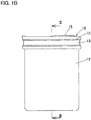
- Figs. 1A to 6 illustrate a thermally insulated container 10 according to the first embodiment of the present invention.
- the thermally insulated container 10 is a mug (the mug is also hereinafter denoted by numeral "10") having a double wall structure, and mainly used outdoors or at home.
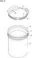
- the mug 10 includes, as its main elements, an inner container part 11, an outer container part 12, and a connection member 13.
- the inner container part 11 is a tubular member having a closed bottom and an open top end, for holding beverages and other items.
- the inner container part 11 has an outer periphery including, at its portion close to the top end, a tapered surface 14 of which the outer diameter decreases toward the bottom end of the inner container part 11.
- the inner container part 11 is made of stainless steel, but it may be made of a resin material if high strength or heat resistance is not required.
- the mug 10 may include a lid 15 disposed at the top end opening of the inner container part 11.
- the lid 15 is formed with a drinking opening 16 and an air hole 17 so that, when a beverage flows out of the inner container part 11 through the drinking opening 16, air simultaneously flows into the inner container part 11 through the air hole 17, thereby enabling the beverage to flow out smoothly.
- a seal member 18 is disposed at the outer peripheral edge of the lid 15 so as to reliably keep the lid 15 fitted in the inner container part 11.
- the thermally insulated container 10 of the embodiment is exemplified as a mug 10 of which the lid 15 has a drinking opening 16 and an air hole 17 so that a user can drink the beverage in the inner container part 11 with the lid 15 attached.
- the drinking opening 16 and the air hole 17 may be omitted to provide heat insulating and sealing properties to the lid 15.
- the thermally insulated container 10 including such a lid 15 can be used not only as a mug 10, but as e.g., a pot or a jar.
- the outer container part 12 is a tubular member having a closed bottom and an open top end, in which the inner container part 11 is received.
- the outer container part 12 has a uniform outer diameter from its top end to its bottom end.
- the outer container part 12 is made of the same material as the inner container part 11, i.e., stainless steel, but it may be made of a resin material so that heat is not transferred from the mug 10 to a user's hand gripping the mug 10. Also, if lightness in weight is important, the outer container part 12 may be made of titanium, aluminum, or an alloy thereof.
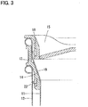
- the inner diameter of the outer container part 12 at its open end is equal to the inner diameter of the inner container part 11 at its open end (see Fig. 3 ). Therefore, instead of putting the lid 15 on the inner container part 11, the lid 15 can be put on the top end opening of the outer container part 12, too.
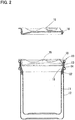
- connection member 13 With the inner container part 11 received in the outer container part 12, the connection member 13 defines a sealed space having a predetermined size between the outer peripheral surface of the inner container part 11 and the inner peripheral surface of the outer container part 12.
- the connection member 13 is disposed between the upper end portions of the inner and outer container parts 11 and 12.
- the connection member 13 has, on its inner periphery, a tapered surface 19 of which the inner diameter decreases axially downwardly of the connection member 13.
- the tapered surface 19 is disposed along the tapered surface 14 of the inner container part 11.
- the lower end portion of the connection member 13that is located below the tapered surface 19 has a smaller diameter than the upper end portion of the connection member 13 that is located above the tapered surface 19.
- the connection member 13 is formed by injection molding of a resin material, and is rigid enough not to be deformed to a large degree when the inner container part 11 is inserted into the outer container part 12.
- the connection member 13 includes a plurality of radially inwardly rising protrusions 20 on the radially inner surface of its upper end portion; and a plurality of radially inwardly rising protrusions 21 on the radially inner surface of its lower end portion (see Fig. 6 ).
- the protrusions 20 and 21 are ribs extending in the axial direction of the connection member 13.
- the protrusions 20, 21 on each of the upper and lower end portions of the connection members 13 are exemplified as three protrusions circumferentially disposed at intervals of 120 degrees, but the positions and the number of the protrusions 20, 21 are not particularly limited, and may be altered as necessary.
- a seal member 22 is disposed at the radially outer surface of the lower end portion of the connection member 13.
- the seal member 22 is made of silicon resin, and reliably keeps the connection member 13 fitted in the outer container part 12 even if the connection member 13 is a rigid injection-molded member. While, in the embodiment, the connection member 13 and the seal member 22 are separate members, they may be formed integrally with each other using a relatively soft material such as silicon resin.
- connection member 13 partially covers the upper end portion of the inner container part 11 (see Fig. 2 ), thus reducing the contact area of a user's lips with the upper end portion of the inner container part 11. This minimizes the sensation of heat felt when the user's lips touch the inner container part 11 with a high-temperature beverage in the mug 10 (i.e., in the inner container part 11.
- connection member 13 is fitted into the top end opening of the outer container part 12.
- inner container part 11 is inserted through the connection member 13 and into the outer container part 12 so as to be arranged coaxially with the outer container part 12.
- the protrusions 21 of the connection member 13 on the radially inner surface of its lower end portion come into contact with the lower end portion (small diameter portion) of the inner container part 11.
- the protrusions 21 come into substantially line contact with the lower end portion of the inner container part 11, and are shaped so as to guide the insertion of the lower end portion of the inner container part 11, it is possible to minimize the friction between the inner container part 11 and the connection member 13, and thus to smoothly insert the inner container part 11.
- the inner container part 11 and the outer container part 12 are not coaxial with each other at the initial stage of the insertion, the inner container part 11 eventually becomes coaxial with the outer container part 12 due to the tapered surface 14 of the inner container part 11 coming into surface contact with the tapered surface 19 of the connection member 13.
- the protrusions 20 of the connection member 13 on the radially inner surface of its upper end portion strongly abut against the upper end portion (large diameter portion) of the inner container part 11, so that the inner container part 11 is reliably retained by the connection member 13 (and thus by the outer container part 12). This reliably prevents the separation of the inner container part 11when the mug 10 is tilted.
- a heating or cooling medium such as refrigerant, ice water or hot water may be placed in the sealed space between the inner container part 11 and the outer container part 12 so that the contents of the mug 10 can be not only simply kept at an elevated or reduced temperature,, but also positively heated or cooled.
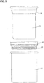
- Fig. 7 illustrates a mug 10 according to the second embodiment of the present invention.
- the mug 10 of the second embodiment is identical in basic structure to the mug 10 of the first embodiment, but the shapes of the inner container part 11, outer container part 12 and connection member 13 are different.
- the mug 10 of the second embodiment has, besides the tapered surface on the inner container part 11, an additional tapered surface on the outer container part 12, and thus the outer shape of the mug 10 is such that its lower end portion is slimmer than its upper end portion.
- two seal members 22 are disposed on the outer periphery of the connection member 13 so as to be vertically spaced apart from each other, thereby ensuring airtightness between the outer container part 12 and the connection member 13.
- An externally mounted member 23 is disposed on the outer peripheral surface of an upper end portion of the outer container part 12. The externally mounted member 23 is provided to enable a user to grip the mug 10 more reliably (easily).
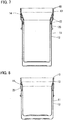
- Fig. 8 illustrates a mug 10 according to the third embodiment of the present invention.
- the mug 10 of the third embodiment is identical in basic structure to the mug 10 of the first embodiment, but the shape of the connection member 13 is different.
- connection member 13 of the mug 10 has no seal member 22, and is wedged between the inner and outer container parts 11 and 12 by the force with which the inner container part 11 is fitted into the outer container part 12.
- the connection member 13 of this embodiment is preferably made of silicon resin, a material having flexibility.
- An externally mounted member 23 is disposed on the outer peripheral surface of the upper end portion of the outer container part 12. The externally mounted member enables a user to grip the mug 10 more reliably (easily).
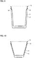
- Fig. 9 illustrates a mug 10 according to the fourth embodiment of the present invention.
- the mug 10 of the fourth embodiment is identical in basic structure to the mug 10 of the first embodiment, but the shapes of the inner container part 11, outer container part 12 and connection member 13 are different.
- the inner container part 11 of the mug 10 has a tapered surface 14 near its top end, and has an outer diameter that gradually decreases from the tapered surface 14 to the bottom end of the inner container part 11.
- the outer container part 12 has an outer diameter that gradually decreases from a portion of the outer container part 12 close to its top end to its bottom end. Therefore, the outer shape of the mug 10 is such that its lower end portion is slimmer than its upper end portion.
- the connection member 13 has no seal member 22, and is wedged between the inner and outer container parts 11 and 12 by the force with which the inner container part 11 is fitted into the outer container part 12. In this arrangement, since the shape of the connection member 13 can be simplified, it may be possible to reduce the manufacturing cost, as in the third embodiment.
- Fig. 10 illustrates a mug 10 according to the fifth embodiment of the present invention.
- the mug 10 of the fifth embodiment is identical in basic structure to the mug 10 of the first embodiment, but the shapes of the inner container part 11, outer container part 12 and connection member 13 are different.
- the inner and outer container parts 11 and 12 of the mug 10 according to the fifth embodiment are identical in shape to each other, and each has an outer diameter that gradually decreases from a portion of the container part close to its top end to its bottom end.
- the connection member 13 has no seal member 22, and is wedged between the inner and outer container parts 11 and 12 by the force with which the inner container part 11 is fitted into the outer container part 12. In this arrangement, since the inner and outer container parts 11 and 12 can be formed with the same mold, and the shape of the connection member 13 can be simplified, it may be possible to reduce the manufacturing cost.
- the shapes of the elements of the mug 10, such as the inner container part 11, the outer container part 12 and the connection member 13, may be altered as necessary, provided that the object of the present invention, i.e., to provide a thermally insulated container having a multiple wall structure which can be constructed in an simple manner, and which is capable of keeping its contents at an elevated or reduced temperature, can be achieved.
- the mug 10 may have a triple or more wall structure.
- Such a mug 10 may show an improved ability to keep its contents at an elevated or reduced temperature.
- a portion of the outer container part 12 or the connection member 13 of the mug 10 may have the function of a simplified valve element or air pump capable of discharging air in the space between the two walls of the mug (thereby creating a vacuum or a decompressed state in this space). This further improves the ability of the mug 10 to keep its contents at an elevated or reduced temperature, compared to when there is an air layer at atmospheric pressure in the space between the two walls of the mug 10.
Landscapes
- Engineering & Computer Science (AREA)
- Mechanical Engineering (AREA)
- Packages (AREA)
- Table Devices Or Equipment (AREA)
- Thermally Insulated Containers For Foods (AREA)
Applications Claiming Priority (2)
| Application Number | Priority Date | Filing Date | Title |
|---|---|---|---|
| JP2017161065A JP2019038560A (ja) | 2017-08-24 | 2017-08-24 | 断熱容器 |
| PCT/JP2018/029238 WO2019039236A1 (fr) | 2017-08-24 | 2018-08-03 | Contenant à isolation thermique |
Publications (2)
| Publication Number | Publication Date |
|---|---|
| EP3674232A1 true EP3674232A1 (fr) | 2020-07-01 |
| EP3674232A4 EP3674232A4 (fr) | 2020-07-01 |
Family
ID=65438764
Family Applications (1)
| Application Number | Title | Priority Date | Filing Date |
|---|---|---|---|
| EP18849142.7A Withdrawn EP3674232A4 (fr) | 2017-08-24 | 2018-08-03 | Contenant à isolation thermique |
Country Status (5)
| Country | Link |
|---|---|
| US (1) | US20210163211A1 (fr) |
| EP (1) | EP3674232A4 (fr) |
| JP (1) | JP2019038560A (fr) |
| KR (1) | KR20200044009A (fr) |
| WO (1) | WO2019039236A1 (fr) |
Families Citing this family (6)
| Publication number | Priority date | Publication date | Assignee | Title |
|---|---|---|---|---|
| US11786061B2 (en) | 2018-04-05 | 2023-10-17 | Vinglace Llc | Insulated food and beverage container |
| US11089906B2 (en) | 2018-04-05 | 2021-08-17 | Vinglacé, LLC | Insulated food and beverage container |
| USD871852S1 (en) | 2018-08-09 | 2020-01-07 | Vinglacé, LLC | Beverage tumbler |
| US20220204223A1 (en) * | 2019-05-16 | 2022-06-30 | Lidtek As | Lid with a fastening mechanism for tightening a lid skirt around a sidewall of a pail and a pail for said lid and a thermally insulated compound pail |
| TWI762940B (zh) * | 2020-05-29 | 2022-05-01 | 新加坡商酷博股份有限公司 | 保溫瓶 |
| KR102637986B1 (ko) * | 2022-12-01 | 2024-02-16 | 조희 | 냉각 특성이 향상된 컵 |
Family Cites Families (13)
| Publication number | Priority date | Publication date | Assignee | Title |
|---|---|---|---|---|
| JPS5645354Y2 (fr) * | 1976-12-03 | 1981-10-23 | ||
| US20130221013A1 (en) * | 1997-04-07 | 2013-08-29 | J. Bruce Kolowich | Thermal receptacle with phase change material |
| US20040212120A1 (en) * | 2001-05-25 | 2004-10-28 | Jean-Pierre Giraud | Dual wall insulated overmold cup assembly and a method of manufacturing an insulated overmold cup assembly |
| JP2006069612A (ja) * | 2004-09-01 | 2006-03-16 | Honda Motor Co Ltd | 燃料タンクのシール構造 |
| JP4984053B2 (ja) | 2007-03-15 | 2012-07-25 | 東洋製罐株式会社 | 二重構造成形体の製造方法及び製造装置 |
| JP5110381B2 (ja) * | 2007-08-28 | 2012-12-26 | 株式会社ジェイテクト | 保護カバー、この保護カバーを有する車輪用転がり軸受装置 |
| JP3138983U (ja) * | 2007-09-28 | 2008-01-31 | 剛 岩渕 | 冷蔵容器 |
| US9585501B1 (en) * | 2013-11-12 | 2017-03-07 | L. Robert Hamelink | Beverage cup insulating seal member and associated insulated beverage cup assembly |
| DE102013114552A1 (de) * | 2013-12-19 | 2015-06-25 | Pi-Design Ag | Doppelwandiges Trinkgefäß |
| JP5826874B2 (ja) * | 2014-02-20 | 2015-12-02 | 株式会社セブン・セブン | コーヒー収納容器 |
| US20160088960A1 (en) * | 2014-09-29 | 2016-03-31 | Hsiao-Chen Liang | Tumbler with a bi-layer structure |
| JP6628403B2 (ja) * | 2015-12-28 | 2020-01-08 | 信越ファインテック株式会社 | 容器用連結部材 |
| JP3203301U (ja) * | 2016-01-08 | 2016-03-24 | 有限会社ユタカ産業 | 飲料用容器 |
-
2017
- 2017-08-24 JP JP2017161065A patent/JP2019038560A/ja active Pending
-
2018
- 2018-08-03 WO PCT/JP2018/029238 patent/WO2019039236A1/fr unknown
- 2018-08-03 EP EP18849142.7A patent/EP3674232A4/fr not_active Withdrawn
- 2018-08-03 KR KR1020207006276A patent/KR20200044009A/ko not_active Application Discontinuation
- 2018-08-03 US US16/641,486 patent/US20210163211A1/en not_active Abandoned
Also Published As
| Publication number | Publication date |
|---|---|
| US20210163211A1 (en) | 2021-06-03 |
| JP2019038560A (ja) | 2019-03-14 |
| KR20200044009A (ko) | 2020-04-28 |
| WO2019039236A1 (fr) | 2019-02-28 |
| EP3674232A4 (fr) | 2020-07-01 |
Similar Documents
| Publication | Publication Date | Title |
|---|---|---|
| EP3674232A1 (fr) | Contenant à isolation thermique | |
| US10478000B2 (en) | Insulated cup with double wall construction | |
| AU2017280047B2 (en) | Lid for container | |
| US20220071424A1 (en) | Thermal regulation and stabilization vessel | |
| US11751707B2 (en) | Insulated beverage container | |
| US20160270572A1 (en) | Lid assemblies for drinking vessels and drinking vessels including the same | |
| US20170305641A1 (en) | Double-walled drinking vessel | |
| CN104135899A (zh) | 手柄 | |
| US20170367536A1 (en) | Stainless steel food service vessels | |
| KR200464363Y1 (ko) | 강제체결 방식을 이용한 단열용 삼중용기 | |
| KR102376066B1 (ko) | 단열 용기용 진공 밀봉 리드 인서트 | |
| KR101560679B1 (ko) | 보온 용기 | |
| MX2008009314A (es) | Enfriador para objetos cilindricos. | |
| KR20170031354A (ko) | 결로 방지용 음료용기 | |
| US20120223076A1 (en) | Cup system with removable insulated liner | |
| KR102074305B1 (ko) | 열에 의한 변형을 최소화시키기 위한 용기 및 이의 제조방법 | |
| KR102637986B1 (ko) | 냉각 특성이 향상된 컵 | |
| KR200474750Y1 (ko) | 컵의 상단에 결합하여 이종의 음료를 음용할 수 있는 용기 | |
| US20230146911A1 (en) | Temperature-conserving containers | |
| US20220175167A1 (en) | Insulated Cup Holder | |
| KR20180001394U (ko) | 이중빨대 |
Legal Events
| Date | Code | Title | Description |
|---|---|---|---|
| STAA | Information on the status of an ep patent application or granted ep patent |
Free format text: STATUS: THE INTERNATIONAL PUBLICATION HAS BEEN MADE |
|
| PUAI | Public reference made under article 153(3) epc to a published international application that has entered the european phase |
Free format text: ORIGINAL CODE: 0009012 |
|
| STAA | Information on the status of an ep patent application or granted ep patent |
Free format text: STATUS: REQUEST FOR EXAMINATION WAS MADE |
|
| 17P | Request for examination filed |
Effective date: 20200304 |
|
| A4 | Supplementary search report drawn up and despatched |
Effective date: 20200527 |
|
| AK | Designated contracting states |
Kind code of ref document: A1 Designated state(s): AL AT BE BG CH CY CZ DE DK EE ES FI FR GB GR HR HU IE IS IT LI LT LU LV MC MK MT NL NO PL PT RO RS SE SI SK SM TR |
|
| AX | Request for extension of the european patent |
Extension state: BA ME |
|
| DAV | Request for validation of the european patent (deleted) | ||
| DAX | Request for extension of the european patent (deleted) | ||
| STAA | Information on the status of an ep patent application or granted ep patent |
Free format text: STATUS: THE APPLICATION IS DEEMED TO BE WITHDRAWN |
|
| 18D | Application deemed to be withdrawn |
Effective date: 20210112 |