EP3674093A1 - Flüssigkeitsausstossvorrichtung, flüssigkeitsausstossgerät und färbegerät - Google Patents
Flüssigkeitsausstossvorrichtung, flüssigkeitsausstossgerät und färbegerät Download PDFInfo
- Publication number
- EP3674093A1 EP3674093A1 EP19211125.0A EP19211125A EP3674093A1 EP 3674093 A1 EP3674093 A1 EP 3674093A1 EP 19211125 A EP19211125 A EP 19211125A EP 3674093 A1 EP3674093 A1 EP 3674093A1
- Authority
- EP
- European Patent Office
- Prior art keywords
- liquid discharge
- carriage
- head
- liquid
- guide shaft
- Prior art date
- Legal status (The legal status is an assumption and is not a legal conclusion. Google has not performed a legal analysis and makes no representation as to the accuracy of the status listed.)
- Withdrawn
Links
- 239000007788 liquid Substances 0.000 title claims abstract description 98
- 238000004043 dyeing Methods 0.000 title claims description 14
- 230000008878 coupling Effects 0.000 claims abstract description 17
- 238000010168 coupling process Methods 0.000 claims abstract description 17
- 238000005859 coupling reaction Methods 0.000 claims abstract description 17
- 238000006073 displacement reaction Methods 0.000 claims description 6
- 230000005540 biological transmission Effects 0.000 claims description 3
- 239000000463 material Substances 0.000 description 8
- 238000012423 maintenance Methods 0.000 description 7
- 238000005259 measurement Methods 0.000 description 7
- 239000000975 dye Substances 0.000 description 4
- 230000008859 change Effects 0.000 description 3
- 230000000052 comparative effect Effects 0.000 description 3
- 229920000742 Cotton Polymers 0.000 description 2
- 102000053602 DNA Human genes 0.000 description 2
- 108020004414 DNA Proteins 0.000 description 2
- 230000008901 benefit Effects 0.000 description 2
- 239000003086 colorant Substances 0.000 description 2
- 229910052751 metal Inorganic materials 0.000 description 2
- 239000002184 metal Substances 0.000 description 2
- 238000000034 method Methods 0.000 description 2
- 238000012805 post-processing Methods 0.000 description 2
- 210000002268 wool Anatomy 0.000 description 2
- OYPRJOBELJOOCE-UHFFFAOYSA-N Calcium Chemical compound [Ca] OYPRJOBELJOOCE-UHFFFAOYSA-N 0.000 description 1
- 150000001413 amino acids Chemical class 0.000 description 1
- 239000000560 biocompatible material Substances 0.000 description 1
- 229910052791 calcium Inorganic materials 0.000 description 1
- 239000011575 calcium Substances 0.000 description 1
- 238000004140 cleaning Methods 0.000 description 1
- 150000001875 compounds Chemical class 0.000 description 1
- 230000001419 dependent effect Effects 0.000 description 1
- 238000001035 drying Methods 0.000 description 1
- 239000000839 emulsion Substances 0.000 description 1
- 239000004744 fabric Substances 0.000 description 1
- 239000003365 glass fiber Substances 0.000 description 1
- 230000002401 inhibitory effect Effects 0.000 description 1
- 230000002452 interceptive effect Effects 0.000 description 1
- 239000000314 lubricant Substances 0.000 description 1
- 230000007246 mechanism Effects 0.000 description 1
- 239000003960 organic solvent Substances 0.000 description 1
- 239000000049 pigment Substances 0.000 description 1
- 229920000642 polymer Polymers 0.000 description 1
- 230000008569 process Effects 0.000 description 1
- 102000004169 proteins and genes Human genes 0.000 description 1
- 108090000623 proteins and genes Proteins 0.000 description 1
- 239000011347 resin Substances 0.000 description 1
- 229920005989 resin Polymers 0.000 description 1
- 238000009958 sewing Methods 0.000 description 1
- 239000002904 solvent Substances 0.000 description 1
- 239000004094 surface-active agent Substances 0.000 description 1
- 239000000725 suspension Substances 0.000 description 1
- XLYOFNOQVPJJNP-UHFFFAOYSA-N water Substances O XLYOFNOQVPJJNP-UHFFFAOYSA-N 0.000 description 1
- 238000009941 weaving Methods 0.000 description 1
- 238000004804 winding Methods 0.000 description 1
Images



Classifications
-
- B—PERFORMING OPERATIONS; TRANSPORTING
- B41—PRINTING; LINING MACHINES; TYPEWRITERS; STAMPS
- B41J—TYPEWRITERS; SELECTIVE PRINTING MECHANISMS, i.e. MECHANISMS PRINTING OTHERWISE THAN FROM A FORME; CORRECTION OF TYPOGRAPHICAL ERRORS
- B41J19/00—Character- or line-spacing mechanisms
- B41J19/18—Character-spacing or back-spacing mechanisms; Carriage return or release devices therefor
- B41J19/20—Positive-feed character-spacing mechanisms
- B41J19/202—Drive control means for carriage movement
-
- D—TEXTILES; PAPER
- D06—TREATMENT OF TEXTILES OR THE LIKE; LAUNDERING; FLEXIBLE MATERIALS NOT OTHERWISE PROVIDED FOR
- D06B—TREATING TEXTILE MATERIALS USING LIQUIDS, GASES OR VAPOURS
- D06B1/00—Applying liquids, gases or vapours onto textile materials to effect treatment, e.g. washing, dyeing, bleaching, sizing or impregnating
- D06B1/02—Applying liquids, gases or vapours onto textile materials to effect treatment, e.g. washing, dyeing, bleaching, sizing or impregnating by spraying or projecting
-
- B—PERFORMING OPERATIONS; TRANSPORTING
- B41—PRINTING; LINING MACHINES; TYPEWRITERS; STAMPS
- B41J—TYPEWRITERS; SELECTIVE PRINTING MECHANISMS, i.e. MECHANISMS PRINTING OTHERWISE THAN FROM A FORME; CORRECTION OF TYPOGRAPHICAL ERRORS
- B41J19/00—Character- or line-spacing mechanisms
- B41J19/04—Sound-deadening or shock-absorbing devices or measures therein
-
- B—PERFORMING OPERATIONS; TRANSPORTING
- B41—PRINTING; LINING MACHINES; TYPEWRITERS; STAMPS
- B41J—TYPEWRITERS; SELECTIVE PRINTING MECHANISMS, i.e. MECHANISMS PRINTING OTHERWISE THAN FROM A FORME; CORRECTION OF TYPOGRAPHICAL ERRORS
- B41J25/00—Actions or mechanisms not otherwise provided for
- B41J25/001—Mechanisms for bodily moving print heads or carriages parallel to the paper surface
- B41J25/003—Mechanisms for bodily moving print heads or carriages parallel to the paper surface for changing the angle between a print element array axis and the printing line, e.g. for dot density changes
-
- D—TEXTILES; PAPER
- D05—SEWING; EMBROIDERING; TUFTING
- D05C—EMBROIDERING; TUFTING
- D05C11/00—Devices for guiding, feeding, handling, or treating the threads in embroidering machines; Machine needles; Operating or control mechanisms therefor
- D05C11/24—Devices for guiding, feeding, handling, or treating the threads in embroidering machines; Machine needles; Operating or control mechanisms therefor incorporating devices for dyeing or impregnating the threads
-
- D—TEXTILES; PAPER
- D06—TREATMENT OF TEXTILES OR THE LIKE; LAUNDERING; FLEXIBLE MATERIALS NOT OTHERWISE PROVIDED FOR
- D06B—TREATING TEXTILE MATERIALS USING LIQUIDS, GASES OR VAPOURS
- D06B11/00—Treatment of selected parts of textile materials, e.g. partial dyeing
- D06B11/002—Treatment of selected parts of textile materials, e.g. partial dyeing of moving yarns
- D06B11/0023—Treatment of selected parts of textile materials, e.g. partial dyeing of moving yarns by spraying or pouring
-
- B—PERFORMING OPERATIONS; TRANSPORTING
- B41—PRINTING; LINING MACHINES; TYPEWRITERS; STAMPS
- B41J—TYPEWRITERS; SELECTIVE PRINTING MECHANISMS, i.e. MECHANISMS PRINTING OTHERWISE THAN FROM A FORME; CORRECTION OF TYPOGRAPHICAL ERRORS
- B41J2202/00—Embodiments of or processes related to ink-jet or thermal heads
- B41J2202/01—Embodiments of or processes related to ink-jet heads
- B41J2202/20—Modules
-
- B—PERFORMING OPERATIONS; TRANSPORTING
- B41—PRINTING; LINING MACHINES; TYPEWRITERS; STAMPS
- B41J—TYPEWRITERS; SELECTIVE PRINTING MECHANISMS, i.e. MECHANISMS PRINTING OTHERWISE THAN FROM A FORME; CORRECTION OF TYPOGRAPHICAL ERRORS
- B41J3/00—Typewriters or selective printing or marking mechanisms characterised by the purpose for which they are constructed
- B41J3/407—Typewriters or selective printing or marking mechanisms characterised by the purpose for which they are constructed for marking on special material
- B41J3/4078—Printing on textile
-
- D—TEXTILES; PAPER
- D06—TREATMENT OF TEXTILES OR THE LIKE; LAUNDERING; FLEXIBLE MATERIALS NOT OTHERWISE PROVIDED FOR
- D06B—TREATING TEXTILE MATERIALS USING LIQUIDS, GASES OR VAPOURS
- D06B2700/00—Treating of textile materials, e.g. bleaching, dyeing, mercerising, impregnating, washing; Fulling of fabrics
- D06B2700/09—Apparatus for passing open width fabrics through bleaching, washing or dyeing liquid
Definitions
- the present disclosure relates to a liquid discharge device, and a liquid discharge apparatus and a dyeing apparatus including the liquid discharge device.
- Liquid discharge apparatuses include a head (a liquid discharge head) to discharge a liquid.
- the liquid discharge head is mounted on a carriage that reciprocates to move the head back and forth between a home position for head maintenance and a discharge position at which the head discharges the liquid.
- a structure that includes a guide shaft that guides the carriage, a bearing provided in the carriage and fitted with the guide shaft, and a timing belt that applies, to the carriage, a driving force for moving the carriage.
- the timing belt is coupled to the carriage at a position above the bearing (for example, JP-2002-337415-A ).
- an object of the present disclosure is to reduce changes in posture of the head when the head is moved.
- the liquid discharge device includes a liquid discharge head including a nozzle face in which a nozzle is formed and configured to discharge a liquid, a carriage on which the liquid discharge head is mounted, and a guide shaft configured to hold the carriage movably.
- the liquid discharge device further includes a driver configured to move the carriage, and a coupling between the carriage and the driver. The coupling is disposed on an axis of the guide shaft in a direction orthogonal to the axis of the guide shaft.
- a liquid discharge apparatus includes the liquid discharge device described above.
- a dyeing apparatus includes the liquid discharge device described above.
- FIG. 1 is a schematic view of the liquid discharge apparatus.
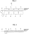
- FIG. 2 is a view of a liquid application unit of the liquid discharge apparatus.
- FIG. 3 is a view of a row of heads of the liquid application unit as viewed from below.
- a liquid discharge apparatus 100 is an in-line embroidery machine.
- the liquid discharge apparatus 100 includes a supply reel 102 on which a thread 101 (a linear material, as a target of liquid application) is wound, a liquid application unit 103 (a liquid application device), a fixing unit 104, a post-processing unit 105, and an embroidery head 106.
- the thread 101 drawn from the supply reel 102 is guided by rollers 108 and 109 and continuously stretched to the embroidery head 106.
- the liquid application unit 103 (the liquid discharge device) includes a plurality of heads 1 (1a to 1d) and a plurality of individual maintenance units 2 (2a to 2d).
- the liquid application unit 103 discharges a liquid of a required color onto the thread 101 which is drawn out from the supply reel 102.
- the individual maintenance units 2 perform maintenance of the heads 1, respectively.
- the heads 1a to 1d discharge, for example, cyan (C), magenta (M), yellow (Y), and black (K) color liquids.
- each of the heads 1 (1a to 1d) includes a nozzle plate in which a plurality of nozzles 11 to discharge a liquid is formed. Specifically, on a face (hereinafter "nozzle face 12") of the nozzle plate, the plurality of nozzles 11 is lined in a nozzle row 10. Each head 1 is disposed such that the nozzle row direction (the arrangement of the nozzles 11) matches the direction of conveyance (movement direction) of the thread 101.
- the fixing unit 104 performs a fixing process (drying process) of the thread 101 to which the liquid is applied from the liquid application unit 103.
- the fixing unit 104 includes, for example, a heater such as an infrared irradiation device and a hot air sprayer, and heats the thread 101 to dry.
- the post-processing unit 105 includes, for example, a cleaning device that cleans the thread 101, a tension adjustment device that adjusts the tension of the thread 101, a feed amount detector that detects the amount of movement of the thread 101, and a lubricant application device that lubricates the surface of the thread 101.
- the embroidery head 106 embroiders a pattern, for example, on a cloth with the thread 101.
- liquid discharge apparatus in the present embodiment is an embroidery machine
- the present disclosure is not limited thereto. Aspects of the present disclosure are applicable to devices, such as weaving machines and sewing machines, that use linear objects such as threads. Further, aspects of the present disclosure can be applied not only to apparatuses having a post-process, such as an embroidery machine, but also to dyeing apparatuses and the like that dye and wind threads, etc. as described later.
- “thread” includes glass fiber thread, wool thread, cotton thread, synthetic thread, metal thread, wool, cotton, polymer, mixed metal thread, yarn, filament, and linear objects (continuous base materials) to which liquid is applicable.
- the “thread” also includes braids and flat cords (flat braids).
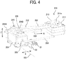
- FIG. 4 is a perspective view illustrating a portion of the liquid application unit relating to one head, according to the first embodiment.
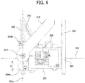
- FIG. 5 is a plan view illustrating a main part of the liquid application unit.
- FIG. 6 is a bottom view of the main part of the liquid application unit.
- FIG. 7 is a front view of the main part of the liquid application unit.
- the head 1 is mounted on a carriage 201 that can reciprocate in the direction indicated by arrow X, and the head 1 is moved between a home position where the head 1 is capped with the cap 21 of the individual maintenance unit 2 and a discharge position (dyeing position) where the head 1 discharges the liquid onto the thread 101.
- the individual maintenance unit 2 further includes, in addition to the cap 21, a wiper 22 to wipe the nozzle face 12, and the cap 21 is coupled to a suction device.
- the carriage 201 is held by a main guide shaft 202 and a sub-guide member 203 and reciprocally movable.
- the sub-guide member 203 is illustrated as a shaft in the present embodiment, but the sub-guide member 203 can be a stay or the like.
- the carriage 201 includes two bearings 204 (204A and 204B) that are fitted on the main guide shaft 202 to allow the main guide shaft 202 to move.
- the two bearings 204A and 204B are apart from each other in the axial direction of the main guide shaft 202.
- the carriage 201 can be modified to include one bearing.
- the carriage 201 includes protruding supports 205 that sandwich the sub-guide member 203 from above and below in FIG. 4 .
- the carriage 201 can further include a bearing that fits on the sub-guide member 203 so that the sub-guide member 203 can move.
- the carriage 201 is provided with a driver 210 that reciprocates the carriage 201.
- the driver 210 includes a motor 211 and a crank 212 that is a drive force transmission member and moved by the motor 211.
- a rear end (right end in FIG. 4 ) of the crank 212 is rotatably attached to an arm 213 coupled to a motor shaft 211a.
- a front end (left end in FIG. 4 ) of the crank 212 is rotatably coupled to the carriage 201 by a support shaft 215.
- the support shaft 215 is a coupling between the carriage 201 and the driver 210.
- the coupling (the support shaft 215) between the carriage 201 and the crank 212 of the driver 210 is located on the axis 202a of the main guide shaft 202.
- the coupling (the support shaft 215) can be located between the two bearings 204A and 204B.
- the coupling (the support shaft 215) can be disposed between both ends of the bearing 204A and 204B (between the left end of the bearing 204A and the right end of the bearing 204B in FIG. 4 ), which can be expressed "between both ends of at least one bearing".
- the direction perpendicular to the axis 202a of the main guide shaft 202 is the vertical direction (Z direction), and the support shaft 215 is on a vertical line 202b (see FIG. 7 ) passing through the axis 202a.
- the support shaft 215 is disposed between the two bearings 204A and 204B.
- the support shaft 215 is disposed between the both ends of the bearing.
- the direction perpendicular to the axis of the main guide shaft 202 is not limited to the vertical direction.
- the coupling between the carriage 201 and the crank 212 of the driver 210 is disposed at a center between the two bearings 204A and 204B.
- the carriage 201 is repeatedly moved between the home position where the head 1 is capped with the cap 21 and the discharge position where the thread 101 is dyed (printed) and stopped at the home position and the discharge position.
- the coupling (the support shaft 215) between the crank 212 and the carriage 201 is disposed in the direction vertical to the axis 202a of the main guide shaft 202 and between the two bearings 204A and 204B.
- This arrangement can reduce the moment that changes the posture of the head 1 (the posture of the nozzle row 10) when a force for moving the carriage 201 from the home position to the discharge position is applied. Accordingly, without reducing a clearance between the bearing 204 and the main guide shaft 202, changes in the posture of the head 1 caused by load fluctuations can be inhibited.
- the nozzle row 10 of the head 1 and the thread 101 can be aligned with each other with high accuracy, and the discharged liquid can reliably land on the thread 101.
- the alignment between the nozzle row 10 and the thread 101 is important to ensure that the liquid lands on the thin thread 101.
- the posture change of the carriage 201 at the stop is easily occurs due to the clearance between the bearing 204 of the carriage 201 and the main guide shaft 202. Therefore, the posture of the head 1 easily changes.
- the nozzle 11 deviates from the thread 101 and is likely to discharge droplets that do not land on the thread 101. Then, the thread 101 is not dyed to a desired density. If droplets of a specific color do not land on the thread 101, the color reproducibility deteriorates.
- the coupling between the carriage 201 and the driver 210 is disposed on the axis 202a of the main guide shaft 202 in the direction perpendicular to the axis 202a.
- Such arrangement can minimize the posture change of the head 1 when the head 1 is moved to the discharge position. Further, when the coupling is disposed between the two bearings 204A and 204B in the axial direction, the posture change of the head 1 can be further reduced.
- FIG. 8 is a chart of an example of measurement result of positional deviation of the carriage according to the present embodiment.
- FIG. 9 is a chart of an example of measurement result of positional deviation of a carriage according to a comparative example.
- a tension coil spring 220 which is an elastic member, is disposed between the carriage 201 and a fixed portion (e.g., a housing of the liquid application unit 103). When viewed from the main guide shaft 202, the tension coil spring 220 is coupled to the carriage 201 at a position apart from a connection to the carriage 201 of the supply tube 230 that supplies the liquid to the head 1.
- the tension coil spring 220 is disposed so as to pull the carriage 201 obliquely downward (in the direction indicated by arrow A illustrated in FIGS. 4 and 7 ) with respect to the axis 202a of the main guide shaft 202.
- the protruding support 205 of the carriage 201 is pressed against the sub-guide member 203 from above, and the contact between the protruding support 205 and the sub-guide member 203 is secured.
- the carriage 201 according to the present embodiment was moved and stopped a plurality of times, and deviations of the actual stop position from a target stop position were measured.
- FIG. 8 illustrates the result of measurement.
- FIG. 9 illustrates the result of measurement.
- providing the tension coil spring 220 can reduce the stop position deviations of the carriage 201, thereby inhibiting changes in the posture.
- FIG. 10 is a bottom view of a carriage according to the second embodiment.
- the head 1 is attached to a head holder 151, and the head holder 151 is supported on the carriage 201.
- One corner of the head holder 151 is held rotatably on the carriage 201 by a support shaft 251. Accordingly, the head 1 held on the carriage 201 can rotate in the in-plane direction of the nozzle face 12.
- the head 1 is provided with an adjuster 252 to adjust the angle at which the nozzle row 10 of the head 1 crosses the axis 202a of the main guide shaft 202.
- the adjuster 252 includes an adjusting screw 253, serving as an operated member, and a lever 254, serving as a transmission member.
- the adjusting screw 253 is attached to the carriage 201 and moves forward and backward in the direction indicated by arrow Y1.
- the lever 254 is moved by the adjusting screw 253 and rotates the head 1 with a displacement amount smaller than the displacement amount of the adjusting screw 253.
- the lever 254 is rotatably supported on the carriage 201 with a support shaft 255 and includes a curved bulge 254a that contacts a contact part 151a of the head holder 151.
- the adjusting screw 253 of the adjuster 252 As the adjusting screw 253 of the adjuster 252 is rotated (operated), the adjusting screw 253 pushes and rotates the lever 254. Then, the bulge 254a of the lever 254 presses the contact part 151a of the head holder 151, thereby rotating the head holder 151 about the support shaft 251 as a fulcrum, and the head 1 rotates.
- the displacement of the adjusting screw 253 is converted into the rotation of the lever 254, the displacement amount of the adjusting screw 253 transmitted to the head holder 151 can be reduced. Therefore, the crossing angle of the nozzle row 10 can be adjusted with a high accuracy.
- the nozzle row 10 of the head 1 can be aligned with the direction along the thread 101, and liquid can land on the thread 101 with high accuracy, thereby improving the color reproducibility.
- FIG. 11 is a front view of the liquid application unit 103 according to the third embodiment.
- the four heads 1 are arranged in the nozzle arrangement direction along the conveyance direction indicated of the thread 101. Therefore, the four carriages 201 (201a to 201d) on which the heads 1 (1a to 1d) are respectively mounted are arranged along the conveyance direction of the thread 101.
- the bearings 204A and 204B (see FIG. 4 ) that fit around the main guide shaft 202 are disposed at one end of the carriage 201, and the protruding supports 205 that engage with the sub-guide member 203 are disposed at the other end of the carriage 201.
- the bearings 204 and the protruding supports 205 are apart from each other in the height direction in FIG. 11 .
- the bearings 204 of one carriage 201 are inhibited from interfering with the protruding supports 205 of the adjacent carriage 201. Accordingly, the arrangement length of the plurality of carriages 201 can be shortened.
- FIG. 12 is a schematic view of the dyeing apparatus.
- a dyeing apparatus 1000 the embroidery head 106 in the liquid discharge apparatus 100 is replaced with a take-up reel 107 for winding the thread 101 after dyeing.
- the dyeing apparatus 1000 supplies the thread 101 from the supply reel 102, discharges a liquid of a required color from the liquid application unit 103, dyes the thread 101 into a target color, and winds the dyed thread 101 with the take-up reel 107.
- liquid discharged from a liquid discharge head is not particularly limited as long as the liquid has a viscosity and surface tension of degrees dischargeable from the liquid discharge head.
- the liquid include a solution, a suspension, or an emulsion that contains, for example, a solvent, such as water or an organic solvent, a colorant, such as dye or pigment, a functional material, such as a polymerizable compound, a resin, or a surfactant, a biocompatible material, such as deoxyribonucleic acid (DNA), amino acid, protein, or calcium, or an edible material, such as a natural colorant.
Landscapes
- Engineering & Computer Science (AREA)
- Textile Engineering (AREA)
- Chemical & Material Sciences (AREA)
- Materials Engineering (AREA)
- Treatment Of Fiber Materials (AREA)
- Ink Jet (AREA)
Applications Claiming Priority (1)
| Application Number | Priority Date | Filing Date | Title |
|---|---|---|---|
| JP2018248200A JP7196605B2 (ja) | 2018-12-28 | 2018-12-28 | 液体を吐出する装置、吐出ユニット、染色装置 |
Publications (1)
| Publication Number | Publication Date |
|---|---|
| EP3674093A1 true EP3674093A1 (de) | 2020-07-01 |
Family
ID=68655315
Family Applications (1)
| Application Number | Title | Priority Date | Filing Date |
|---|---|---|---|
| EP19211125.0A Withdrawn EP3674093A1 (de) | 2018-12-28 | 2019-11-25 | Flüssigkeitsausstossvorrichtung, flüssigkeitsausstossgerät und färbegerät |
Country Status (3)
| Country | Link |
|---|---|
| US (1) | US11939715B2 (de) |
| EP (1) | EP3674093A1 (de) |
| JP (1) | JP7196605B2 (de) |
Families Citing this family (2)
| Publication number | Priority date | Publication date | Assignee | Title |
|---|---|---|---|---|
| WO2020137383A1 (en) * | 2018-12-28 | 2020-07-02 | Ricoh Company, Ltd. | Liquid discharge apparatus, dyeing apparatus, embroidery machine, and maintenance device |
| US11267269B2 (en) * | 2019-11-28 | 2022-03-08 | Ricoh Company, Ltd. | Recording-head position adjustment mechanism, recording-head module, and image forming apparatus |
Citations (15)
| Publication number | Priority date | Publication date | Assignee | Title |
|---|---|---|---|---|
| JPS4951123U (de) * | 1972-08-09 | 1974-05-07 | ||
| JPH0230574A (ja) * | 1988-07-21 | 1990-01-31 | Canon Inc | シリアル記録装置 |
| US5388919A (en) * | 1992-04-10 | 1995-02-14 | Brother Kogyo Kabushiki Kaisha | Printing device with a tiltable printing head |
| JPH09146184A (ja) * | 1995-11-20 | 1997-06-06 | Ricoh Co Ltd | キャリッジ駆動装置 |
| US5880757A (en) * | 1991-11-04 | 1999-03-09 | Hewlett-Packard Company | Print resolution enhancement by adjusting printhead position |
| JP2002337415A (ja) | 2001-03-15 | 2002-11-27 | Canon Inc | キャリッジを備える装置 |
| EP1674279A1 (de) * | 2004-12-22 | 2006-06-28 | Agfa-Gevaert | Positionierungsanordnung |
| US20060139400A1 (en) * | 2004-12-29 | 2006-06-29 | Océ-Technologies B.V. | Printhead carriage |
| JP2007276288A (ja) * | 2006-04-07 | 2007-10-25 | Seiko Epson Corp | ヘッド取付位置調整機構及び液体噴射装置と記録装置 |
| US20110254896A1 (en) * | 2008-12-30 | 2011-10-20 | Telecom Italia S.P.A. | Inkjet printhead, in particular for sewing/embroidering machines, a method for making said inkjet printhead, and a method for coloring a thread |
| NL2008063C2 (en) * | 2012-01-02 | 2013-07-03 | Mutracx B V | Inkjet printing system. |
| US20150165799A1 (en) * | 2012-07-16 | 2015-06-18 | Padaluma Ink-Jet-Solutions Gmbh & Co. Kg | Print Head Adjustment Device |
| US20160375707A1 (en) * | 2014-03-26 | 2016-12-29 | Oce-Technologies B.V. | Mounting structure for a plurality of print head units |
| US20170313108A1 (en) * | 2016-05-02 | 2017-11-02 | Memjet Technology Ltd. | Modular printer having print bar chassis seated on maintenance chassis |
| EP3275675A1 (de) * | 2016-07-26 | 2018-01-31 | Ricoh Company, Ltd. | Vorrichtung zur durchführung einer operation auf einem geförderten objekt |
Family Cites Families (19)
| Publication number | Priority date | Publication date | Assignee | Title |
|---|---|---|---|---|
| US6116728A (en) * | 1992-02-26 | 2000-09-12 | Canon Kabushiki Kaisha | Ink jet recording method and apparatus and recorded matter |
| JPH0691896A (ja) * | 1992-09-09 | 1994-04-05 | Canon Inc | インクジェット記録装置 |
| JP3066937B2 (ja) | 1993-04-12 | 2000-07-17 | キヤノン株式会社 | インクジェット染色刺繍方法及び装置 |
| JPH06305129A (ja) | 1993-04-23 | 1994-11-01 | Canon Inc | インクジェットプリント装置及び方法及びそれを備えた刺繍装置 |
| JPH06304359A (ja) | 1993-04-23 | 1994-11-01 | Canon Inc | 縫製機及びその刺繍製品 |
| US6056454A (en) * | 1998-10-05 | 2000-05-02 | Gerber Technology, Inc. | Method and apparatus for printing on a continuously moving sheet of work material |
| JP4176393B2 (ja) * | 2002-06-12 | 2008-11-05 | シャープ株式会社 | インクジェット画像形成装置 |
| JP4258190B2 (ja) * | 2002-08-30 | 2009-04-30 | コニカミノルタホールディングス株式会社 | 記録ヘッドの取付構造、プリンタ及び記録ヘッドの取付方法 |
| US6896430B2 (en) * | 2002-10-23 | 2005-05-24 | Hewlett-Packard Development Company, L.P. | Compliant belt attach |
| US20060132529A1 (en) * | 2004-12-22 | 2006-06-22 | Bart Verhoest | Positioning system |
| JP4508903B2 (ja) | 2005-02-22 | 2010-07-21 | 株式会社リコー | 画像形成装置 |
| JP5691466B2 (ja) * | 2010-12-10 | 2015-04-01 | セイコーエプソン株式会社 | 液体噴射ヘッドユニット、および、その製造方法 |
| JP6319948B2 (ja) * | 2013-04-23 | 2018-05-09 | キヤノン株式会社 | 記録装置 |
| JP6098465B2 (ja) * | 2013-09-30 | 2017-03-22 | ブラザー工業株式会社 | 液体吐出装置、パターン群記録方法、傾斜角度検出方法、及びプログラム |
| GB2528843B (en) * | 2014-07-30 | 2020-06-03 | Inca Digital Printers Ltd | Printhead attachment system |
| JP5980392B1 (ja) * | 2015-08-28 | 2016-08-31 | ローランドディー.ジー.株式会社 | インクジェットヘッドおよびそれを備えたプリンタ |
| JP6581489B2 (ja) * | 2015-12-11 | 2019-09-25 | エスアイアイ・プリンテック株式会社 | キャリッジおよび液体噴射記録装置 |
| US20170165960A1 (en) | 2015-12-14 | 2017-06-15 | Ricoh Company, Ltd. | Liquid ejection apparatus, liquid ejection system, and liquid ejection method |
| JP7005893B2 (ja) | 2015-12-14 | 2022-01-24 | 株式会社リコー | 液体を吐出する装置、液体を吐出するシステム及び液体を吐出する方法 |
-
2018
- 2018-12-28 JP JP2018248200A patent/JP7196605B2/ja active Active
-
2019
- 2019-11-25 EP EP19211125.0A patent/EP3674093A1/de not_active Withdrawn
- 2019-12-16 US US16/714,839 patent/US11939715B2/en active Active
Patent Citations (15)
| Publication number | Priority date | Publication date | Assignee | Title |
|---|---|---|---|---|
| JPS4951123U (de) * | 1972-08-09 | 1974-05-07 | ||
| JPH0230574A (ja) * | 1988-07-21 | 1990-01-31 | Canon Inc | シリアル記録装置 |
| US5880757A (en) * | 1991-11-04 | 1999-03-09 | Hewlett-Packard Company | Print resolution enhancement by adjusting printhead position |
| US5388919A (en) * | 1992-04-10 | 1995-02-14 | Brother Kogyo Kabushiki Kaisha | Printing device with a tiltable printing head |
| JPH09146184A (ja) * | 1995-11-20 | 1997-06-06 | Ricoh Co Ltd | キャリッジ駆動装置 |
| JP2002337415A (ja) | 2001-03-15 | 2002-11-27 | Canon Inc | キャリッジを備える装置 |
| EP1674279A1 (de) * | 2004-12-22 | 2006-06-28 | Agfa-Gevaert | Positionierungsanordnung |
| US20060139400A1 (en) * | 2004-12-29 | 2006-06-29 | Océ-Technologies B.V. | Printhead carriage |
| JP2007276288A (ja) * | 2006-04-07 | 2007-10-25 | Seiko Epson Corp | ヘッド取付位置調整機構及び液体噴射装置と記録装置 |
| US20110254896A1 (en) * | 2008-12-30 | 2011-10-20 | Telecom Italia S.P.A. | Inkjet printhead, in particular for sewing/embroidering machines, a method for making said inkjet printhead, and a method for coloring a thread |
| NL2008063C2 (en) * | 2012-01-02 | 2013-07-03 | Mutracx B V | Inkjet printing system. |
| US20150165799A1 (en) * | 2012-07-16 | 2015-06-18 | Padaluma Ink-Jet-Solutions Gmbh & Co. Kg | Print Head Adjustment Device |
| US20160375707A1 (en) * | 2014-03-26 | 2016-12-29 | Oce-Technologies B.V. | Mounting structure for a plurality of print head units |
| US20170313108A1 (en) * | 2016-05-02 | 2017-11-02 | Memjet Technology Ltd. | Modular printer having print bar chassis seated on maintenance chassis |
| EP3275675A1 (de) * | 2016-07-26 | 2018-01-31 | Ricoh Company, Ltd. | Vorrichtung zur durchführung einer operation auf einem geförderten objekt |
Also Published As
| Publication number | Publication date |
|---|---|
| US20200208317A1 (en) | 2020-07-02 |
| JP2020104497A (ja) | 2020-07-09 |
| JP7196605B2 (ja) | 2022-12-27 |
| US11939715B2 (en) | 2024-03-26 |
Similar Documents
| Publication | Publication Date | Title |
|---|---|---|
| US10974511B2 (en) | Liquid discharge device, and liquid discharge apparatus and dyeing apparatus including same | |
| US20180185884A1 (en) | Liquid ejecting apparatus, and cleaning method of transport belt of liquid ejecting apparatus | |
| US8201508B2 (en) | Needle thread feeding device for multi-needle embroidery sewing machine | |
| US11939715B2 (en) | Liquid discharge device, liquid discharge apparatus, and dyeing apparatus | |
| TWI593847B (zh) | 多頭刺繡機 | |
| KR20180017201A (ko) | 인라인 스레드 처리 장치 및 방법 | |
| EP3867071B1 (de) | Verfahren zur in-line-behandlung eines fadens und system dafür mit einer behandlungseinheit und einer steuerungseinheit mit konfiguration zur bestimmung, ob eine wartungssequenz erforderlich ist | |
| EP3850136B1 (de) | System zur in-line-behandlung von garn mit einem mechanismus zur selektiven positionierung einer entladungsvorrichtung | |
| US20220098778A1 (en) | Liquid application unit for linear medium, liquid application apparatus, dyeing embroidery system, control method, and storage medium | |
| EP3722100B1 (de) | Druckgerät | |
| JP2021112871A (ja) | 液体を吐出する装置、染色装置、刺繍装置、液体回収方法 | |
| JP2022064780A (ja) | 液体を吐出する装置、染色装置 | |
| US11701906B2 (en) | Recording device | |
| US20240399763A1 (en) | Printing apparatus and printing method | |
| US20080289525A1 (en) | Driving System for the Cylinder Cleaning Assemblies of Printing Machines |
Legal Events
| Date | Code | Title | Description |
|---|---|---|---|
| PUAI | Public reference made under article 153(3) epc to a published international application that has entered the european phase |
Free format text: ORIGINAL CODE: 0009012 |
|
| STAA | Information on the status of an ep patent application or granted ep patent |
Free format text: STATUS: REQUEST FOR EXAMINATION WAS MADE |
|
| 17P | Request for examination filed |
Effective date: 20191125 |
|
| AK | Designated contracting states |
Kind code of ref document: A1 Designated state(s): AL AT BE BG CH CY CZ DE DK EE ES FI FR GB GR HR HU IE IS IT LI LT LU LV MC MK MT NL NO PL PT RO RS SE SI SK SM TR |
|
| AX | Request for extension of the european patent |
Extension state: BA ME |
|
| GRAP | Despatch of communication of intention to grant a patent |
Free format text: ORIGINAL CODE: EPIDOSNIGR1 |
|
| STAA | Information on the status of an ep patent application or granted ep patent |
Free format text: STATUS: GRANT OF PATENT IS INTENDED |
|
| RIC1 | Information provided on ipc code assigned before grant |
Ipc: B41J 19/20 20060101ALI20220221BHEP Ipc: B41J 2/21 20060101ALI20220221BHEP Ipc: B41J 25/34 20060101ALI20220221BHEP Ipc: B41J 25/00 20060101ALI20220221BHEP Ipc: B41J 2/14 20060101ALI20220221BHEP Ipc: D05C 11/24 20060101ALI20220221BHEP Ipc: B41J 19/00 20060101ALI20220221BHEP Ipc: D06B 11/00 20060101ALI20220221BHEP Ipc: D05C 11/00 20060101ALI20220221BHEP Ipc: D06P 5/30 20060101ALI20220221BHEP Ipc: B41J 25/316 20060101ALI20220221BHEP Ipc: B41J 25/304 20060101ALI20220221BHEP Ipc: B41J 3/407 20060101AFI20220221BHEP |
|
| GRAS | Grant fee paid |
Free format text: ORIGINAL CODE: EPIDOSNIGR3 |
|
| INTG | Intention to grant announced |
Effective date: 20220310 |
|
| STAA | Information on the status of an ep patent application or granted ep patent |
Free format text: STATUS: THE APPLICATION IS DEEMED TO BE WITHDRAWN |
|
| 18D | Application deemed to be withdrawn |
Effective date: 20220721 |