EP3673879B1 - Perforiergerät für ein band , verfahren und machine - Google Patents
Perforiergerät für ein band , verfahren und machine Download PDFInfo
- Publication number
- EP3673879B1 EP3673879B1 EP19209410.0A EP19209410A EP3673879B1 EP 3673879 B1 EP3673879 B1 EP 3673879B1 EP 19209410 A EP19209410 A EP 19209410A EP 3673879 B1 EP3673879 B1 EP 3673879B1
- Authority
- EP
- European Patent Office
- Prior art keywords
- deformation member
- web
- advancement path
- deformation
- along
- Prior art date
- Legal status (The legal status is an assumption and is not a legal conclusion. Google has not performed a legal analysis and makes no representation as to the accuracy of the status listed.)
- Active
Links
Images


Classifications
-
- A—HUMAN NECESSITIES
- A61—MEDICAL OR VETERINARY SCIENCE; HYGIENE
- A61F—FILTERS IMPLANTABLE INTO BLOOD VESSELS; PROSTHESES; DEVICES PROVIDING PATENCY TO, OR PREVENTING COLLAPSING OF, TUBULAR STRUCTURES OF THE BODY, e.g. STENTS; ORTHOPAEDIC, NURSING OR CONTRACEPTIVE DEVICES; FOMENTATION; TREATMENT OR PROTECTION OF EYES OR EARS; BANDAGES, DRESSINGS OR ABSORBENT PADS; FIRST-AID KITS
- A61F13/00—Bandages or dressings; Absorbent pads
- A61F13/15—Absorbent pads, e.g. sanitary towels, swabs or tampons for external or internal application to the body; Supporting or fastening means therefor; Tampon applicators
- A61F13/15577—Apparatus or processes for manufacturing
- A61F13/15707—Mechanical treatment, e.g. notching, twisting, compressing, shaping
-
- B—PERFORMING OPERATIONS; TRANSPORTING
- B26—HAND CUTTING TOOLS; CUTTING; SEVERING
- B26F—PERFORATING; PUNCHING; CUTTING-OUT; STAMPING-OUT; SEVERING BY MEANS OTHER THAN CUTTING
- B26F1/00—Perforating; Punching; Cutting-out; Stamping-out; Apparatus therefor
- B26F1/24—Perforating by needles or pins
-
- A—HUMAN NECESSITIES
- A61—MEDICAL OR VETERINARY SCIENCE; HYGIENE
- A61F—FILTERS IMPLANTABLE INTO BLOOD VESSELS; PROSTHESES; DEVICES PROVIDING PATENCY TO, OR PREVENTING COLLAPSING OF, TUBULAR STRUCTURES OF THE BODY, e.g. STENTS; ORTHOPAEDIC, NURSING OR CONTRACEPTIVE DEVICES; FOMENTATION; TREATMENT OR PROTECTION OF EYES OR EARS; BANDAGES, DRESSINGS OR ABSORBENT PADS; FIRST-AID KITS
- A61F13/00—Bandages or dressings; Absorbent pads
- A61F13/15—Absorbent pads, e.g. sanitary towels, swabs or tampons for external or internal application to the body; Supporting or fastening means therefor; Tampon applicators
- A61F13/15577—Apparatus or processes for manufacturing
- A61F13/15707—Mechanical treatment, e.g. notching, twisting, compressing, shaping
- A61F13/15731—Treating webs, e.g. for giving them a fibrelike appearance, e.g. by embossing
-
- A—HUMAN NECESSITIES
- A61—MEDICAL OR VETERINARY SCIENCE; HYGIENE
- A61F—FILTERS IMPLANTABLE INTO BLOOD VESSELS; PROSTHESES; DEVICES PROVIDING PATENCY TO, OR PREVENTING COLLAPSING OF, TUBULAR STRUCTURES OF THE BODY, e.g. STENTS; ORTHOPAEDIC, NURSING OR CONTRACEPTIVE DEVICES; FOMENTATION; TREATMENT OR PROTECTION OF EYES OR EARS; BANDAGES, DRESSINGS OR ABSORBENT PADS; FIRST-AID KITS
- A61F13/00—Bandages or dressings; Absorbent pads
- A61F13/15—Absorbent pads, e.g. sanitary towels, swabs or tampons for external or internal application to the body; Supporting or fastening means therefor; Tampon applicators
- A61F13/15577—Apparatus or processes for manufacturing
- A61F13/15764—Transferring, feeding or handling devices; Drives
-
- B—PERFORMING OPERATIONS; TRANSPORTING
- B26—HAND CUTTING TOOLS; CUTTING; SEVERING
- B26F—PERFORATING; PUNCHING; CUTTING-OUT; STAMPING-OUT; SEVERING BY MEANS OTHER THAN CUTTING
- B26F3/00—Severing by means other than cutting; Apparatus therefor
- B26F3/06—Severing by using heat
- B26F3/08—Severing by using heat with heated members
Definitions
- Embodiments of the present invention relate to a perforating apparatus of a web usable in a machine for producing sanitary absorbent articles, such as diapers, diaper-pants, incontinence pads, sanitary pads, or other articles intended to absorb bodily fluids.
- embodiments of the present invention relate to a perforating apparatus of a web capable of making a plurality of holes in a web intended for making sanitary absorbent articles.
- the present invention also relates to a process for perforating a web capable of making in a precise and controlled way a plurality of holes in a web, as well as a machine for producing sanitary absorbent articles comprising one or more perforating apparatuses.
- sanitary absorbent articles In the production of sanitary absorbent articles, it is known to use webs having one or more zones in which holes have been made which give the sanitary absorbent article particular properties.
- perforated webs can give breathability, diversified elasticity, or other properties in relation to the desired requirements.
- That known solution involves high costs, requires lengthy times for loading in machine and for supplying, and necessitates large warehouse spaces and numbers of personnel.
- the joined together protrusions of the two rollers engage the web and jointly make a plurality of holes in the web.
- the holes in the web may have unwanted elliptical shapes and/or lacerated and/or stretched portions, or in the worst cases the web may even remain accidentally caught in the perforating apparatus.
- One aim of the present invention is to supply a perforating apparatus capable of making holes in a web in line which are precise and without imperfections so as to obtain sanitary absorbent articles corresponding to design expectations with high production rates.
- a further aim of the present invention is to supply a machine for producing sanitary absorbent articles comprising at least one perforating apparatus which allows deformations to be made in one or more desired zones of the web in a precise and controlled way.
- the present invention relates to a perforating apparatus of at least one web advancing along an advancement path at an advancing velocity.
- the perforating apparatus comprises at least one first deformation member provided with a plurality of openings and at least one second deformation member provided with a plurality of protruding elements.
- the first deformation member and the second deformation member are configured to position themselves at least in a tracking position, wherein the first deformation member and the second deformation member are placed on opposite sides of the advancement path and facing each other.
- the first deformation member and the second deformation member are configured to position themselves in a coupling position, wherein the protruding elements are coupled with the openings orthogonally to the advancement path to make, in use, a plurality of holes in a zone of the web.
- the web In the coupling position, in use, the web is clamped between the first deformation member and the second deformation member so that the protruding elements perforate the web.
- the first deformation member and the second deformation member in the tracking position and in the coupling position, are configured to advance along a portion parallel to the advancement path at the advancing velocity so as to make the plurality of holes with relative velocities, at least along the advancement path, between the first deformation member and the web and between the second deformation member and the web which are substantially zero.
- the present invention allows the making of holes in a web in a precise and controlled way, without the resulting holes having unwanted shapes, simultaneously guaranteeing that the web is not lacerated and proceeds at the advancing velocity of the web without slowing or jamming.
- the present invention overcomes the problems relative to the known solutions which use pairs of rollers which do not allow the obtainment of precise and circular holes.
- known solutions which use plates with perforating elements they are not capable of making holes with a circular shape and without instantaneously slowing the advancing of the web at least in correspondence with the engagement zone of the perforating elements with the web.
- the first deformation member comprises a first plate wherein the openings are present.
- the second deformation member comprises a second plate wherein the protruding elements are present.
- the perforating apparatus comprises disengaging means interposed between the first deformation member and the second deformation member in the coupling position configured to disengage the web from the protruding elements so that, in use, the perforated web is freed from the protruding elements.
- the disengaging means comprise at least one disengaging element provided with at least one through opening wherein in the coupling position the protruding elements are inserted.
- the disengaging element may comprise a plurality of through openings.
- the perforating apparatus comprises a heating device configured to heat the protruding elements.
- the perforating apparatus comprises retaining means placed along two directions parallel to the advancement path, arranged laterally to the zone of the web wherein, in use, the holes are made.
- the retaining means are configured to position themselves in contact with the web for retaining the web in contact with the first deformation member or the second deformation member.
- the perforating apparatus may comprise a plurality of first deformation members and a plurality of said second deformation members, wherein each of the first deformation members and of the second deformation members is configured to move independently of the others.
- part of the surface of the first deformation member oriented, in the tracking position, towards the second deformation member is coated with a coating.
- the coating may comprise silicone material.
- the first deformation member and/or the second deformation member are configured to position themselves along a direction transverse to the advancement path so that the first deformation member and the second deformation member are at least partially overlapping each other.
- the first deformation member and the second deformation member may be entirely overlapping each other and staggered along the direction transverse to the advancement path of the web, while the web advances along the advancement path.
- the first deformation member and/or the second deformation member are configured to position themselves along a direction transverse to the advancement path so that the first deformation member and the second deformation member are partially overlapping each other.
- the first deformation member and the second deformation member may be partially overlapping each other, while the web advances along the advancement path.
- the present invention also relates to a process for perforating at least one web, comprising:
- the perforating process provides that the first deformation member and/or the second deformation member are positioned along a direction transverse to the advancement path so that the first deformation member and the second deformation member are at least partially overlapping each other to couple with the web and make the plurality of holes in a zone of the web, wherein the zone extends along the transverse direction for an extension less than the transverse extension of the web relative to the advancement path.
- the perforating process provides that the first deformation member and/or the second deformation member are positioned along a direction transverse to the advancement path so that the first deformation member and the second deformation member are partially overlapping each other to couple with the web and make the plurality of holes in a zone of the web, wherein the zone extends along the transverse direction for an extension less than the transverse extension of the web relative to the advancement path.
- the perforating process provides that protruding elements are heated by means of a heating device.
- the perforating process provides that disengaging means separate the web from the protruding elements so as to free the web from the protruding elements.
- the perforating process provides that retaining means position themselves in contact with the web along two directions parallel to the advancement path, arranged laterally to the zone of the web wherein holes are made to retain the web in contact with the first deformation member or the second deformation member.
- the present invention also relates to a machine for producing sanitary absorbent articles comprising at least one perforating apparatus according to any of the possible embodiments.
- Embodiments described herein, with reference to the figures, relate to a perforating apparatus 10 of at least one web 11 advancing along an advancement path P at an advancing velocity to make a plurality of holes 13 in one or more zones of the web 11 itself.
- the advancement path P may comprise a straight portion. According to possible embodiments the advancement path P may comprise a curved portion. According to possible embodiments the advancement path P may comprise a portion inclined with respect to a horizontal geometric plane.
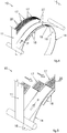
- the present invention allows holes 13 to be made in a web 11 in a precise and controlled way, that is to say, making them according to the design expectations and without imperfections.
- the web 11 has a plurality of holes made according to the prior art and which has many imperfections, such as lacerations, stretching of the web 11, holes which are non-uniform and/or with elongate profiles, or other.
- the web 11 has a plurality of holes 13 made according to a possible embodiment of the present invention, wherein there are none of the imperfections of the web 11 illustrated in Figure 2 such as elongate profiles.
- the web 11 may comprise one or more layers and if necessary even elastic material.
- the elastic material may comprise elastic threads, elastic films, elastic bands, or other.
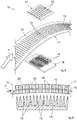
- the perforating apparatus 10 comprises at least one first deformation member 17 provided with a plurality of openings 20.
- the perforating apparatus 10 comprises at least one second deformation member 18 provided with protruding elements 19.
- the openings 20 and the protruding elements 19 are joined together so as to cooperate, in use, to couple with the web 11 and make the plurality of holes 13.
- the openings 20 may comprise through openings, or grooves having a depth such as to allow the respective protruding element 19 to enter the opening 20 without striking the bottom of the opening 20.
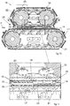
- the first deformation member 17 and the second deformation member 18 are configured to position themselves at least in a tracking position, wherein the first deformation member 17 and the second deformation member 18 are placed on opposite sides of the advancement path P and facing each other.
- the first deformation member 17 and the second deformation member 18 are each facing towards a respective face of the web 11 while it advances along the advancement path P.
- the first deformation member 17 and the second deformation member 18 are configured to position themselves in a coupling position, wherein the protruding elements 19 are coupled with the openings 20 orthogonally to the advancement path P to make, in use, a plurality of holes 13 in a zone of the web 11.
- the movement of the first deformation member 17 and of the second deformation member 18 before and during the engagement with the web 11 combined with the coupling orthogonally to the advancement path P is advantageous and synergic for obtaining precise and circular holes 13, while the web 11 advances without the latter being locally slowed and deformed.
- the protruding elements 19 are facing towards the first deformation member 17 and inserted in the relative openings 20.
- the first deformation member 17 and/or the second deformation member 18 may have a suction system for sucking the web 11 so that in use the latter is retained in position.
- the suction system may comprise a plurality of suction holes arranged on the surface of the first deformation member 17 and/or on the surface of the second deformation member 18 facing towards the advancement path P, wherein the suction holes are fluidly connected to a suction source configured to suck, in use, the web 11 and retain it in position on the desired surface facing towards the advancement path P.
- the suction holes may be arranged on the surface of the first deformation member 17 in the spaces available between the openings 20, or inside the latter.
- the perforating apparatus 10 comprises a first movement unit 21 configured to move the first deformation member 17 at least along a portion parallel to the advancement path P.
- the perforating apparatus 10 comprises a second movement unit 22 configured to move the second deformation member 18 at least along a portion parallel to the advancement path P.
- the first movement unit 21 and the second movement unit 22 are configured to be driven by means of two independent motor members.
- first movement unit 21 and the second movement unit 22 may each comprise a track system provided with a pair of pulleys and a movable track coupled with the pulleys and on which the first deformation member 17 and the second deformation member 18 respectively are connected.
- the first movement unit 21 may be configured to move the first deformation member 17 orthogonally to the advancement path P, even while the first deformation member 17 is moved along a portion parallel to the advancement path P.
- the second movement unit 22 may be configured to move the second deformation member 18 orthogonally to the advancement path P, even while the second deformation member 18 is moved along a portion parallel to the advancement path P.
- the movement orthogonal to the advancement path P by the first deformation member 17 and/or by the second deformation member 18 may be obtained by means of a cam present in the track system which brings the first deformation member 17 and/or the second deformation member 18 into contact with the web 11 along a direction orthogonal to the advancement path P, while the first deformation member 17 and/or the second deformation member 18 travel along the portion parallel to the advancement path P.
- the movement orthogonal to the advancement path by the first deformation member 17 and/or by the second deformation member 18 may be obtained by means of a pusher, a piston, an articulated system, a combination thereof, or other.
- the second movement unit 22 may be configured to move the second deformation member 18 orthogonally to the advancement path P, even while the first movement member 17 is moved along a portion parallel to the advancement path P, and the first movement unit 21 may be configured to move the first deformation member 17 exclusively along a defined path which comprises at least one portion parallel to the advancement path P.
- the coupling position is reached by moving exclusively the second deformation member 18 orthogonally to the advancement path P.
- the parallel portion along which the first deformation member 17 and the second deformation member 18 is moved is defined so that it follows the profile of the curved portion of the advancement path P.
- the first deformation member 17 follows the profile of the curved portion with a first radius of curvature and the second deformation member 18 follows the profile of the curved portion with a second radius of curvature different from the first radius of curvature.
- the first deformation member 17 and the second deformation member 18 are shaped so that the respective openings 20 and the protruding elements 19 are oriented orthogonally to the advancement path P of the web 11.
- the first deformation member 17 and the second deformation member 18 may be moved by means of a common movement unit configured to move both of the deformation members 17 and 18 in a coordinated way.
- the movement unit whether it relates to each deformation member 17 and 18, or to both, is configured to move the deformation members 17 and 18 at least to couple them with the web 11 so as to make the plurality of holes 13 in the desired zone of the web 11.
- first movement unit 21 and the second movement unit 22 may each comprise an actuator, a motor, a motion conversion device, combinations thereof, or other.
- the first deformation member 17 and the second deformation member 18, in the tracking position and in the coupling position are configured to advance along a portion parallel to the advancement path P at the advancing velocity so as to make the plurality of holes 13 with relative velocities, at least along the advancement path P, between the first deformation member 17 and the web 11 and between the second deformation member 18 and the web 11 which are substantially zero.
- the first deformation member 17 and the second deformation member 18 in the tracking position and in the coupling position advance with relative velocities with respect to the web 11 that are substantially zero along the advancement path P.
- the first deformation member 17 and the second deformation member 18 advance at the same advancing velocity as the web 11.
- the possibility given by the present invention to advance the web 11 and make the holes 13 by engaging the web 11 orthogonally and keeping the substantially zero relative velocities at least along the advancement path P between the first deformation member 17 and the web 11 and between the second deformation member 18 and the web 11, allows the obtainment of holes 13 having a substantially circular and not elliptical shape.
- the first deformation member 17 comprises a first plate 23 wherein the openings 20 are present and the second deformation member 18 comprises a second plate 24 wherein the protruding elements 19 are present.
- the plates 23 and 24 may be connected to the relative movement unit 21 and 22 by means of suitable connecting elements.
- the connecting elements may be connected to the relative deformation member 17 and 18 and in turn to the track of the track system.
- the perforating apparatus 10 comprises disengaging means 14 interposed between the first deformation member 17 and the second deformation member 18 in the coupling position configured to disengage the web 11 from the protruding elements 19 so that the perforated web 11 is freed from the protruding elements 19.
- That aspect is advantageous because it allows the perforated web 11 to be rapidly and easily freed from the protruding elements 19.
- the perforated web 11 may be retained in position for example, by disengaging means 14 which act as an opposing element, or pushed towards the opposite direction from which the protruding elements 19 come out of the perforated web 11 to disengage from the latter.
- the disengaging means 14 may be fixed.
- the disengaging means 14 may be configured to adopt an operating position, wherein the disengaging means 14 are interposed between the first deformation member 17 and the second deformation member 18 in the coupling position.
- the disengaging means 14 may be configured to adopt a home position, wherein the disengaging means 14 are not interposed between the first deformation member 17 and the second deformation member 18 in the coupling position.
- the disengaging means 14 may be movable at least between the operating position and the home position.
- the disengaging means 14 may comprise a disengaging element 16 provided with at least one through opening 15 wherein in the coupling position the protruding elements 19 are inserted.
- the disengaging element 16 may comprise a plate which acts as a mechanical opposing element to the perforated web 11 and allows the protruding elements 19 to easily disengage the web 11.
- the disengaging means 14 may comprise nozzles configured to emit a fluid in the direction opposite to the direction of disengagement of the protruding elements 19.
- the direction of disengagement of the protruding elements 19 is the direction opposite to that of engagement with the web 11 for positioning in the coupling position.
- the disengaging element 16 may comprise a plurality of through openings 15 arranged in one or more zones of the disengaging element 16 itself.
- the disengaging element 16 may be configured to advance the web 11 by moving in the direction defined by the advancement path P and bringing with it the web 11 itself, or may act as a support during advancing of the web 11 along the advancement path P which occurs by means of advancing means.
- the advancing means may comprise driven rollers and/or idle rollers, or other elements suitable for advancing the web 11 along the advancement path P.
- the disengaging element 16 may comprise a drum defining along at least part of its perimeter a curved portion of the advancement path P.
- the drum may be configured to rotate around an axis of rotation by means of suitable actuating means.
- the drum may be connected to an actuator, to a motor, to a motion conversion device, or other.
- the first deformation member 17 and the second deformation member 18 are configured to couple with the web 11 jointly in correspondence with the through opening 15 to make a plurality of holes 13 in a zone of the web 11.
- the perforating apparatus 10 comprises a heating device 25 configured to heat the protruding elements 19.
- the heating device may comprise a heating element having a heating surface oriented at least in one portion towards the protruding elements 19 and configured to heat the latter.
- the heating element may be a radiant heat lamp, a hot air emitter, an electromagnetic induction heating device, combinations thereof, or other similar or comparable heating elements.
- the protruding elements 19 and/or the openings 20 may be heated to make a plurality of holes 13.
- the protruding elements 19 and/or the openings 20 may be heated by means of a heating device 25 integrated in the first deformation member 17 and/or in the second deformation member 18.
- the heating device 25 may be configured to bring the temperature of the protruding elements 19 and/or of the openings 20 to a desired temperature.
- the temperature may be greater than the melting threshold of at least one of the components which constitute the web 11.
- a heating device 25 may be placed in correspondence with the infeed zone wherein the web 11 advances, in use, along the advancement path P between at least one first deformation member 17 and one second deformation member 18.
- That heating device 25 is configured to heat the web 11 so as to facilitate the making of the holes 13 by means of the first deformation member 17 and the second deformation member 18.
- the perforating apparatus 10 may comprise a measuring device 26 configured to measure the temperature of the protruding elements 19.
- the perforating apparatus 10 may comprise a measuring device 26 configured to measure the temperature of the web 11.
- the measuring device 26 may comprise a thermal camera, a pyrometer, or a temperature sensor of another type.
- the perforating apparatus 10 may comprise retaining means 27 placed along two directions parallel to the advancement path P, arranged laterally to the zone of the web 11 wherein, in use, the holes 13 are made.
- the retaining means 27 are configured to position themselves in contact with the web 11 for retaining the web 11 in contact with the first deformation member 17 or the second deformation member 18, or in contact with the disengaging means 14.
- That aspect allows the web 11 to be kept spread out so that the ends do not move, or do not retract towards the centre of the web 11, for example in the case of an elastic web 11.
- the perforating apparatus 10 may comprise a plurality of first deformation members 17 and a plurality of said second deformation members 18, wherein each of the first deformation members 17 and of the second deformation members 18 is configured to move independently of the others.
- That aspect allows the achievement of high levels of production flexibility which allow various and different pluralities of holes 13 to be made in one or more predetermined zones of the web 11 as it advances.
- At least part of the surface of the first deformation member 17 oriented, in the tracking position, towards the second deformation member 18 is coated with a coating comprising silicone material.
- first deformation member 17 and/or the second deformation member 18 are configured to position themselves along a direction transverse to the advancement path P so that the first deformation member 17 and the second deformation member 18 are partially overlapping each other.
- the first deformation member 17 and/or the second deformation member 18 are configured to position themselves along a direction transverse to the advancement path P so that the first deformation member 17 and the second deformation member 18 are at least partially overlapping each other.
- the first deformation member 17 may be configured to move along a direction transverse to the advancement path P at least between a first wait position, wherein the first deformation member 17 is placed at the side of the zone wherein the web 11 advances in use, and a second operating position, wherein the first deformation member 17 is at least partially overlapping the zone wherein the web 11 advances in use.
- the movement between the first wait position and the second operating position of the first deformation member 17 may be obtained by means of the first movement unit 21.
- That aspect allows compact dimensions and allows the first deformation member 17 to be positioned in the desired position in relation to the zone of the web 11 wherein the holes 13 are to be made.
- the first deformation member 17 positioning itself in the first wait position allows the use of space typically not used and wherein there are no other components which can interfere with the first deformation member 17.
- the second deformation member 18 may be configured to position itself at least in a wait position, wherein it does not interfere with the web 11 in transit, and at least an operating position, wherein it is coupled with the web 11.
- the present invention also relates to a process for perforating at least one web 11, comprising:
- That aspect allows the obtainment of holes 13 in a web 11 rapidly and as the web 11 advances along an advancement path P directly in line.
- the process provides that the first deformation member 17 and/or the second deformation member 18 are positioned along a direction transverse to the advancement path P so that the first deformation member 17 and the second deformation member 18 are partially overlapping each other to couple with the web 11 and make the plurality of holes 13 in a zone of the web 11, wherein the zone extends along the transverse direction for an extension less than the transverse extension of the web 11 relative to the advancement path P.
- the process provides that the first deformation member 17 and/or the second deformation member 18 are positioned along a direction transverse to the advancement path P so that the first deformation member 17 and the second deformation member 18 are at least partially overlapping each other to couple with the web 11 and make the plurality of holes 13 in a zone of the web 11, wherein the zone extends along the transverse direction for an extension less than the transverse extension of the web 11 relative to the advancement path P.
- the process provides that the protruding elements 19 are heated by means of a heating device 25.
- the process provides that disengaging means 14 disengage the web 11 from the protruding elements 19 so as to free the web 11 from the protruding elements 19.
- the process provides that retaining means 27 position themselves in contact with the web 11 along two directions parallel to the advancement path P, arranged laterally to the zone of the web 11 wherein holes 13 are made to retain the web 11 in contact with the first deformation member 17 or the second deformation member 18, or in contact with the disengaging means 14.
- the retaining means 27 may comprise a pair of elements positionable in contact with the web, such as belts, bars, rollers, plates, or other elements configured to transversally retain the web 11 and to allow it to advance along the advancement path P.
- the present invention also relates to a machine for producing sanitary absorbent articles comprising at least one perforating apparatus 10 according to any of the possible embodiments.
- That aspect allows a plurality of holes 13 to be made in a web 11 as it advances directly in line and simultaneously guarantees reduced likelihoods of the web 11 being able to accidentally become caught in the apparatus 10 itself or in another component of the production machine.
- That aspect also makes it possible to avoid using already perforated webs which involve large warehouse spaces and costs, high disposal costs due to their deterioration and poor flexibility in making different types of holes 13.
- first deformation member 17 and the second deformation member 18 have been described, for expository purposes only and without limiting the scope of the invention, in relation to the possible embodiment illustrated in the drawings.
- first deformation member 17 and the second deformation member 18 may be applied to inverted parts without thereby departing from the scope of the present invention.
- first deformation member 17 may be valid for the second deformation member 18, and vice versa without thereby departing from the scope of the present invention.
Landscapes
- Engineering & Computer Science (AREA)
- Health & Medical Sciences (AREA)
- Life Sciences & Earth Sciences (AREA)
- Mechanical Engineering (AREA)
- Heart & Thoracic Surgery (AREA)
- Manufacturing & Machinery (AREA)
- Epidemiology (AREA)
- Biomedical Technology (AREA)
- Vascular Medicine (AREA)
- Animal Behavior & Ethology (AREA)
- General Health & Medical Sciences (AREA)
- Public Health (AREA)
- Veterinary Medicine (AREA)
- Forests & Forestry (AREA)
- Absorbent Articles And Supports Therefor (AREA)
- Perforating, Stamping-Out Or Severing By Means Other Than Cutting (AREA)
- Shaping Of Tube Ends By Bending Or Straightening (AREA)
Claims (15)
- Perforiereinrichtung für mindestens eine Bahn (11), die sich entlang eines Vorschubwegs (P) mit einer Vorschubgeschwindigkeit vorwärts bewegt, umfassend mindestens ein erstes Verformungselement (17), das mit einer Vielzahl von Öffnungen (20) versehen ist, und mindestens ein zweites Verformungselement (18), das mit einer Vielzahl vorstehender Elemente (19) versehen ist, dadurch gekennzeichnet, dass das erste Verformungselement (17) und das zweite Verformungselement (18) dafür ausgelegt sind, sich zumindest in einer Nachführstellung zu positionieren, in der das erste Verformungselement (17) und das zweite Verformungselement (18) auf entgegengesetzten Seiten des Vorschubwegs (P) platziert sind und einander zugewandt sind, und sich in einer Kopplungsstellung zu positionieren, in der die vorstehenden Elemente (19) mit den Öffnungen (20) orthogonal zu dem Vorschubweg (P) gekoppelt sind, um im Betrieb eine Vielzahl von Löchern (13) in einer Zone der Bahn (11) herzustellen, wobei das erste Verformungselement (17) und das zweite Verformungselement (18) in der Nachführstellung und in der Kopplungsstellung dafür ausgelegt sind, sich entlang eines Abschnitts parallel zu dem Vorschubweg (P) mit der Vorschubgeschwindigkeit vorwärts zu bewegen, um die Vielzahl von Löchern (13) mit zumindest entlang des Vorschubwegs (P) im Wesentlichen null Relativgeschwindigkeiten zwischen dem ersten Verformungselement (17) und der Bahn (11) und zwischen dem zweiten Verformungselement (18) und der Bahn herzustellen.
- Vorrichtung nach Anspruch 1, wobei das erste Verformungselement (17) eine erste Platte (23) umfasst, in der sich die Öffnungen (20) befinden, und das zweite Verformungselement (18) eine zweite Platte (24) umfasst, auf der sich die vorstehenden Elemente (19) befinden.
- Vorrichtung nach Anspruch 1 oder 2, umfassend in der Kopplungsstellung zwischen dem ersten Verformungselement (17) und dem zweiten Verformungselement (18) angeordnete Trennmittel (14), die dafür ausgelegt sind, die Bahn (11) von den vorstehenden Elementen (19) so zu trennen, dass im Betrieb die perforierte Bahn (11) von den vorstehenden Elementen (19) befreit wird.
- Vorrichtung nach Anspruch 3, wobei die Trennmittel (14) mindestens ein Trennelement (16) umfassen, das mit mindestens einer Durchgangsöffnung (15) versehen ist, in die in der Kopplungsstellung die vorstehenden Elemente (19) eingeführt sind.
- Vorrichtung nach einem der vorhergehenden Ansprüche, umfassend eine Heizeinrichtung (25), die dafür ausgelegt ist, die vorstehenden Elemente (19) zu erwärmen.
- Vorrichtung nach einem der vorhergehenden Ansprüche, umfassend Haltemittel (27), die entlang zweier Richtungen parallel zu dem Vorschubweg (P) platziert sind, die seitlich zu der Zone der Bahn (11) angeordnet sind, in der im Betrieb die Löcher (13) hergestellt werden, wobei im Betrieb die Haltemittel (27) dafür ausgelegt sind, sich in Kontakt mit der Bahn (11) zu positionieren, um die Bahn (11) in Kontakt mit dem ersten Verformungselement (17) oder dem zweiten Verformungselement (18) oder in Kontakt mit den Trennmitteln (14) zu halten.
- Vorrichtung nach einem der vorhergehenden Ansprüche, umfassend eine Vielzahl der ersten Verformungselemente (17) und eine Vielzahl der zweiten Verformungselemente (18), wobei jedes der ersten Verformungselemente (17) und der zweiten Verformungselemente (18) dafür ausgelegt ist, sich unabhängig von den anderen zu bewegen.
- Vorrichtung nach einem der vorhergehenden Ansprüche, wobei zumindest ein Teil der in der Nachführstellung zu dem zweiten Verformungselement (18) hin ausgerichteten Oberfläche des ersten Verformungselements (17) mit einer Silikonmaterial umfassenden Beschichtung beschichtet ist.
- Vorrichtung nach einem der vorhergehenden Ansprüche, wobei das erste Verformungselement (17) und/oder das zweite Verformungselement (18) dafür ausgelegt sind, sich entlang einer Richtung quer zu dem Vorschubweg (P) so zu positionieren, dass das erste Verformungselement (17) und das zweite Verformungselement (18) einander zumindest teilweise überlappen.
- Verfahren zum Perforieren mindestens einer Bahn (11), umfassend:- Vorwärtsbewegen der Bahn (11) entlang eines Vorschubwegs (P) mit einer Vorschubgeschwindigkeit,- Positionieren mindestens eines ersten Verformungselements (17), das mit einer Vielzahl von Öffnungen (20) versehen ist, und mindestens eines zweiten Verformungselements (18), das mit einer Vielzahl vorstehender Elemente (19) versehen ist, in einer Nachführstellung, in der das erste Verformungselement (17) und das zweite Verformungselement (18) auf entgegengesetzten Seiten des Vorschubwegs (P) und einander zugewandt in Richtung zweier entgegengesetzter Oberflächen der Bahn (11) weisend platziert sind,- Vorwärtsbewegen des ersten Verformungselements (17) und des zweiten Verformungselements (18) entlang eines Abschnitts parallel zu dem Vorschubweg (P) mit der Vorschubgeschwindigkeit, so dass zumindest entlang des Vorschubwegs (P) die Relativgeschwindigkeiten zwischen dem ersten Verformungselement (17) und der Bahn (11) und zwischen dem zweiten Verformungselement (18) und der Bahn (11) im Wesentlichen null betragen,- Positionieren des ersten Verformungselements (17) und des zweiten Verformungselements (18) in einer Kopplungsposition, in der die vorstehenden Elemente (19) mit den Öffnungen (20) orthogonal zu dem Vorschubweg (P) gekoppelt werden, wobei die Bahn (11) zwischen diesen angeordnet ist, um in einer Zone der Bahn (11) eine Vielzahl von Löchern (13) herzustellen, während sich das erste Verformungselement (17) und das zweite Verformungselement (18) mit der Vorschubgeschwindigkeit entlang eines Abschnitts parallel zu dem Vorschubweg (P) so vorwärts bewegen, dass die Relativgeschwindigkeiten im Wesentlichen null bleiben.
- Verfahren nach Anspruch 10, wobei das erste Verformungselement (17) und/oder das zweite Verformungselement (18) entlang einer Richtung quer zu dem Vorschubweg (P) so positioniert werden, dass das erste Verformungselement (17) und das zweite Verformungselement (18) einander zumindest teilweise überlappen, um in einer Zone der Bahn (11) mit der Bahn (11) zu koppeln und die Vielzahl von Löchern (13) herzustellen, wobei sich die Zone entlang der Querrichtung über eine Erstreckung erstreckt, die geringer ist als die Quererstreckung der Bahn (11) relativ zu dem Vorschubweg (P).
- Verfahren nach Anspruch 10 oder 11, wobei die vorstehenden Elemente (19) mittels einer Heizeinrichtung (25) erwärmt werden.
- Verfahren nach einem der Ansprüche 10 bis 12, wobei die Trennmittel (14) die Bahn (11) von den vorstehenden Elementen (19) trennen, um die Bahn (11) von den vorstehenden Elementen (19) zu befreien.
- Verfahren nach einem der Ansprüche 10 bis 13, wobei sich Haltemittel (27) entlang zweier Richtungen parallel zu dem Vorschubweg (P), die seitlich zu der Zone der Bahn (11) angeordnet sind, in der die Löcher (13) hergestellt werden, in Kontakt mit der Bahn (11) positionieren, um die Bahn (11) in Kontakt mit dem ersten Verformungselement (17) oder dem zweiten Verformungselement (18) zu halten.
- Maschine zur Herstellung saugfähiger Sanitärartikel, umfassend mindestens eine Perforiervorrichtung (10) nach einem der Ansprüche 1 bis 9.
Priority Applications (1)
| Application Number | Priority Date | Filing Date | Title |
|---|---|---|---|
| PL19209410T PL3673879T3 (pl) | 2018-12-27 | 2019-11-15 | Aparat do perforowania wstęgi, sposób perforacji i maszyna do wytwarzania |
Applications Claiming Priority (1)
| Application Number | Priority Date | Filing Date | Title |
|---|---|---|---|
| IT102018000020530A IT201800020530A1 (it) | 2018-12-27 | 2018-12-27 | Apparato e procedimento di deformazione di un telo |
Publications (2)
| Publication Number | Publication Date |
|---|---|
| EP3673879A1 EP3673879A1 (de) | 2020-07-01 |
| EP3673879B1 true EP3673879B1 (de) | 2021-09-08 |
Family
ID=66049474
Family Applications (1)
| Application Number | Title | Priority Date | Filing Date |
|---|---|---|---|
| EP19209410.0A Active EP3673879B1 (de) | 2018-12-27 | 2019-11-15 | Perforiergerät für ein band , verfahren und machine |
Country Status (7)
| Country | Link |
|---|---|
| US (1) | US11529749B2 (de) |
| EP (1) | EP3673879B1 (de) |
| JP (1) | JP3225510U (de) |
| CN (1) | CN211993282U (de) |
| ES (1) | ES2889953T3 (de) |
| IT (1) | IT201800020530A1 (de) |
| PL (1) | PL3673879T3 (de) |
Family Cites Families (11)
| Publication number | Priority date | Publication date | Assignee | Title |
|---|---|---|---|---|
| US4319589A (en) * | 1978-04-07 | 1982-03-16 | Molins Limited | Method and apparatus for perforating rod-like articles |
| US5405561A (en) * | 1993-08-31 | 1995-04-11 | Dowbrands L.P. | Process for microperforating zippered film useful for manufacturing a reclosable zippered bag |
| US5704101A (en) * | 1995-06-05 | 1998-01-06 | Kimberly-Clark Worldwide, Inc. | Creped and/or apertured webs and process for producing the same |
| US6837956B2 (en) * | 2001-11-30 | 2005-01-04 | Kimberly-Clark Worldwide, Inc. | System for aperturing and coaperturing webs and web assemblies |
| US7175727B2 (en) * | 2002-08-30 | 2007-02-13 | Kimberley-Clark Worldwide, Inc. | Shaped absorbent pads and associated method for making |
| US7578954B2 (en) * | 2003-02-24 | 2009-08-25 | Corium International, Inc. | Method for manufacturing microstructures having multiple microelements with through-holes |
| CN101166685B (zh) * | 2005-03-29 | 2010-11-03 | 成功概念公司 | 卷幅处理工艺及设备 |
| US8166857B2 (en) * | 2005-07-01 | 2012-05-01 | Hewlett-Packard Development Company, L.P. | Perforator |
| US8708687B2 (en) * | 2011-04-26 | 2014-04-29 | The Procter & Gamble Company | Apparatus for making a micro-textured web |
| JP2017131397A (ja) * | 2016-01-27 | 2017-08-03 | 花王株式会社 | 微細中空突起具の製造方法 |
| CN109310531B (zh) * | 2016-06-06 | 2019-12-27 | 尤妮佳股份有限公司 | 涉及吸收性物品的连续片的复合体的制造方法以及制造装置 |
-
2018
- 2018-12-27 IT IT102018000020530A patent/IT201800020530A1/it unknown
-
2019
- 2019-11-15 PL PL19209410T patent/PL3673879T3/pl unknown
- 2019-11-15 EP EP19209410.0A patent/EP3673879B1/de active Active
- 2019-11-15 ES ES19209410T patent/ES2889953T3/es active Active
- 2019-12-16 US US16/714,854 patent/US11529749B2/en active Active
- 2019-12-25 JP JP2019004932U patent/JP3225510U/ja active Active
- 2019-12-27 CN CN201922398988.2U patent/CN211993282U/zh active Active
Also Published As
| Publication number | Publication date |
|---|---|
| CN211993282U (zh) | 2020-11-24 |
| IT201800020530A1 (it) | 2020-06-27 |
| PL3673879T3 (pl) | 2021-12-20 |
| JP3225510U (ja) | 2020-03-12 |
| ES2889953T3 (es) | 2022-01-14 |
| US20200206966A1 (en) | 2020-07-02 |
| US11529749B2 (en) | 2022-12-20 |
| EP3673879A1 (de) | 2020-07-01 |
Similar Documents
| Publication | Publication Date | Title |
|---|---|---|
| FI126763B (fi) | Menetelmä ja laite lasilevyjen karkaisemiseksi | |
| EP3673879B1 (de) | Perforiergerät für ein band , verfahren und machine | |
| EP3673880B1 (de) | Vorrichtung zur herstellung von absorbierenden hygieneartikeln mit einer perforationsvorrichtung einer bahn und verfahren | |
| JP2017526125A5 (de) | ||
| CN106658803B (zh) | 一种可调节微波能量分布的加热装置 | |
| JP7633613B2 (ja) | エンボス・ラミネート加工装置におけるエンボス加工ローラの加熱方法及び装置 | |
| CN110891727A (zh) | 能量设备以及向物品提供能量的方法 | |
| KR20040077717A (ko) | 온도 제어 장치 및 방법과, 웨브의 엠보싱 방법 및 웨브의변경 방법 | |
| JP5759732B2 (ja) | ベルト式ロールアイロナー | |
| CN114395884A (zh) | 烘干结构及拉幅烘干机 | |
| EP2244963A1 (de) | Vorrichtung und verfahren zum zentrieren und ausbreiten eines netzes | |
| JP2007021793A (ja) | 竹材の連続的平板化方法及びその装置 | |
| US3264752A (en) | Web treating apparatus | |
| WO2013034990A1 (en) | Apparatus for heat treatment of tubular textile items | |
| KR20100111594A (ko) | 열셋팅기용 원단이송장치 | |
| KR101457074B1 (ko) | 멀티 롤러를 구비한 엠보싱 장치 | |
| JP7337660B2 (ja) | 不織布の製造方法及び不織布の製造装置 | |
| CN207227741U (zh) | 一种一次性内裤用往复式连续自动整形设备 | |
| US20190275727A1 (en) | Oven for preforms | |
| JPH07275Y2 (ja) | 樹脂シート成形機における熱遮蔽装置 | |
| CN106261456B (zh) | 一种用于工业化微波加热的食品加载装置 | |
| CN119704441B (zh) | 一种塑料杯的原料预热装置 | |
| CN221998199U (zh) | 一种用于制作卫生巾吸收体的设备 | |
| JP2021041301A (ja) | 濾紙エレメントの製造方法及び濾紙 | |
| SU818882A1 (ru) | Устройство дл контактного нагреваТЕРМОфОРМуЕМОгО пОлиМЕРНОгОлЕНТОчНОгО МАТЕРиАлА B фОРМОВОчНО-упАКОВОчНыХ ABTOMATAX |
Legal Events
| Date | Code | Title | Description |
|---|---|---|---|
| PUAI | Public reference made under article 153(3) epc to a published international application that has entered the european phase |
Free format text: ORIGINAL CODE: 0009012 |
|
| STAA | Information on the status of an ep patent application or granted ep patent |
Free format text: STATUS: THE APPLICATION HAS BEEN PUBLISHED |
|
| AK | Designated contracting states |
Kind code of ref document: A1 Designated state(s): AL AT BE BG CH CY CZ DE DK EE ES FI FR GB GR HR HU IE IS IT LI LT LU LV MC MK MT NL NO PL PT RO RS SE SI SK SM TR |
|
| AX | Request for extension of the european patent |
Extension state: BA ME |
|
| RAP1 | Party data changed (applicant data changed or rights of an application transferred) |
Owner name: FAMECCANICA.DATA S.P.A. |
|
| STAA | Information on the status of an ep patent application or granted ep patent |
Free format text: STATUS: REQUEST FOR EXAMINATION WAS MADE |
|
| 17P | Request for examination filed |
Effective date: 20201123 |
|
| RBV | Designated contracting states (corrected) |
Designated state(s): AL AT BE BG CH CY CZ DE DK EE ES FI FR GB GR HR HU IE IS IT LI LT LU LV MC MK MT NL NO PL PT RO RS SE SI SK SM TR |
|
| GRAJ | Information related to disapproval of communication of intention to grant by the applicant or resumption of examination proceedings by the epo deleted |
Free format text: ORIGINAL CODE: EPIDOSDIGR1 |
|
| STAA | Information on the status of an ep patent application or granted ep patent |
Free format text: STATUS: GRANT OF PATENT IS INTENDED |
|
| GRAP | Despatch of communication of intention to grant a patent |
Free format text: ORIGINAL CODE: EPIDOSNIGR1 |
|
| RIC1 | Information provided on ipc code assigned before grant |
Ipc: A61F 13/15 20060101AFI20210408BHEP |
|
| INTG | Intention to grant announced |
Effective date: 20210511 |
|
| GRAS | Grant fee paid |
Free format text: ORIGINAL CODE: EPIDOSNIGR3 |
|
| GRAA | (expected) grant |
Free format text: ORIGINAL CODE: 0009210 |
|
| STAA | Information on the status of an ep patent application or granted ep patent |
Free format text: STATUS: THE PATENT HAS BEEN GRANTED |
|
| AK | Designated contracting states |
Kind code of ref document: B1 Designated state(s): AL AT BE BG CH CY CZ DE DK EE ES FI FR GB GR HR HU IE IS IT LI LT LU LV MC MK MT NL NO PL PT RO RS SE SI SK SM TR |
|
| REG | Reference to a national code |
Ref country code: GB Ref legal event code: FG4D |
|
| REG | Reference to a national code |
Ref country code: CH Ref legal event code: EP Ref country code: AT Ref legal event code: REF Ref document number: 1427896 Country of ref document: AT Kind code of ref document: T Effective date: 20210915 |
|
| REG | Reference to a national code |
Ref country code: IE Ref legal event code: FG4D |
|
| REG | Reference to a national code |
Ref country code: DE Ref legal event code: R096 Ref document number: 602019007537 Country of ref document: DE |
|
| REG | Reference to a national code |
Ref country code: SE Ref legal event code: TRGR |
|
| REG | Reference to a national code |
Ref country code: NL Ref legal event code: FP |
|
| REG | Reference to a national code |
Ref country code: LT Ref legal event code: MG9D |
|
| REG | Reference to a national code |
Ref country code: ES Ref legal event code: FG2A Ref document number: 2889953 Country of ref document: ES Kind code of ref document: T3 Effective date: 20220114 |
|
| PG25 | Lapsed in a contracting state [announced via postgrant information from national office to epo] |
Ref country code: RS Free format text: LAPSE BECAUSE OF FAILURE TO SUBMIT A TRANSLATION OF THE DESCRIPTION OR TO PAY THE FEE WITHIN THE PRESCRIBED TIME-LIMIT Effective date: 20210908 Ref country code: LT Free format text: LAPSE BECAUSE OF FAILURE TO SUBMIT A TRANSLATION OF THE DESCRIPTION OR TO PAY THE FEE WITHIN THE PRESCRIBED TIME-LIMIT Effective date: 20210908 Ref country code: BG Free format text: LAPSE BECAUSE OF FAILURE TO SUBMIT A TRANSLATION OF THE DESCRIPTION OR TO PAY THE FEE WITHIN THE PRESCRIBED TIME-LIMIT Effective date: 20211208 Ref country code: FI Free format text: LAPSE BECAUSE OF FAILURE TO SUBMIT A TRANSLATION OF THE DESCRIPTION OR TO PAY THE FEE WITHIN THE PRESCRIBED TIME-LIMIT Effective date: 20210908 Ref country code: HR Free format text: LAPSE BECAUSE OF FAILURE TO SUBMIT A TRANSLATION OF THE DESCRIPTION OR TO PAY THE FEE WITHIN THE PRESCRIBED TIME-LIMIT Effective date: 20210908 Ref country code: NO Free format text: LAPSE BECAUSE OF FAILURE TO SUBMIT A TRANSLATION OF THE DESCRIPTION OR TO PAY THE FEE WITHIN THE PRESCRIBED TIME-LIMIT Effective date: 20211208 |
|
| REG | Reference to a national code |
Ref country code: AT Ref legal event code: MK05 Ref document number: 1427896 Country of ref document: AT Kind code of ref document: T Effective date: 20210908 |
|
| PG25 | Lapsed in a contracting state [announced via postgrant information from national office to epo] |
Ref country code: LV Free format text: LAPSE BECAUSE OF FAILURE TO SUBMIT A TRANSLATION OF THE DESCRIPTION OR TO PAY THE FEE WITHIN THE PRESCRIBED TIME-LIMIT Effective date: 20210908 Ref country code: GR Free format text: LAPSE BECAUSE OF FAILURE TO SUBMIT A TRANSLATION OF THE DESCRIPTION OR TO PAY THE FEE WITHIN THE PRESCRIBED TIME-LIMIT Effective date: 20211209 |
|
| PG25 | Lapsed in a contracting state [announced via postgrant information from national office to epo] |
Ref country code: AT Free format text: LAPSE BECAUSE OF FAILURE TO SUBMIT A TRANSLATION OF THE DESCRIPTION OR TO PAY THE FEE WITHIN THE PRESCRIBED TIME-LIMIT Effective date: 20210908 |
|
| PG25 | Lapsed in a contracting state [announced via postgrant information from national office to epo] |
Ref country code: IS Free format text: LAPSE BECAUSE OF FAILURE TO SUBMIT A TRANSLATION OF THE DESCRIPTION OR TO PAY THE FEE WITHIN THE PRESCRIBED TIME-LIMIT Effective date: 20220108 Ref country code: SM Free format text: LAPSE BECAUSE OF FAILURE TO SUBMIT A TRANSLATION OF THE DESCRIPTION OR TO PAY THE FEE WITHIN THE PRESCRIBED TIME-LIMIT Effective date: 20210908 Ref country code: SK Free format text: LAPSE BECAUSE OF FAILURE TO SUBMIT A TRANSLATION OF THE DESCRIPTION OR TO PAY THE FEE WITHIN THE PRESCRIBED TIME-LIMIT Effective date: 20210908 Ref country code: RO Free format text: LAPSE BECAUSE OF FAILURE TO SUBMIT A TRANSLATION OF THE DESCRIPTION OR TO PAY THE FEE WITHIN THE PRESCRIBED TIME-LIMIT Effective date: 20210908 Ref country code: PT Free format text: LAPSE BECAUSE OF FAILURE TO SUBMIT A TRANSLATION OF THE DESCRIPTION OR TO PAY THE FEE WITHIN THE PRESCRIBED TIME-LIMIT Effective date: 20220110 Ref country code: EE Free format text: LAPSE BECAUSE OF FAILURE TO SUBMIT A TRANSLATION OF THE DESCRIPTION OR TO PAY THE FEE WITHIN THE PRESCRIBED TIME-LIMIT Effective date: 20210908 Ref country code: CZ Free format text: LAPSE BECAUSE OF FAILURE TO SUBMIT A TRANSLATION OF THE DESCRIPTION OR TO PAY THE FEE WITHIN THE PRESCRIBED TIME-LIMIT Effective date: 20210908 Ref country code: AL Free format text: LAPSE BECAUSE OF FAILURE TO SUBMIT A TRANSLATION OF THE DESCRIPTION OR TO PAY THE FEE WITHIN THE PRESCRIBED TIME-LIMIT Effective date: 20210908 |
|
| REG | Reference to a national code |
Ref country code: DE Ref legal event code: R097 Ref document number: 602019007537 Country of ref document: DE |
|
| PG25 | Lapsed in a contracting state [announced via postgrant information from national office to epo] |
Ref country code: MC Free format text: LAPSE BECAUSE OF FAILURE TO SUBMIT A TRANSLATION OF THE DESCRIPTION OR TO PAY THE FEE WITHIN THE PRESCRIBED TIME-LIMIT Effective date: 20210908 |
|
| PLBE | No opposition filed within time limit |
Free format text: ORIGINAL CODE: 0009261 |
|
| STAA | Information on the status of an ep patent application or granted ep patent |
Free format text: STATUS: NO OPPOSITION FILED WITHIN TIME LIMIT |
|
| PG25 | Lapsed in a contracting state [announced via postgrant information from national office to epo] |
Ref country code: LU Free format text: LAPSE BECAUSE OF NON-PAYMENT OF DUE FEES Effective date: 20211115 Ref country code: DK Free format text: LAPSE BECAUSE OF FAILURE TO SUBMIT A TRANSLATION OF THE DESCRIPTION OR TO PAY THE FEE WITHIN THE PRESCRIBED TIME-LIMIT Effective date: 20210908 |
|
| 26N | No opposition filed |
Effective date: 20220609 |
|
| PG25 | Lapsed in a contracting state [announced via postgrant information from national office to epo] |
Ref country code: SI Free format text: LAPSE BECAUSE OF FAILURE TO SUBMIT A TRANSLATION OF THE DESCRIPTION OR TO PAY THE FEE WITHIN THE PRESCRIBED TIME-LIMIT Effective date: 20210908 |
|
| PG25 | Lapsed in a contracting state [announced via postgrant information from national office to epo] |
Ref country code: IE Free format text: LAPSE BECAUSE OF NON-PAYMENT OF DUE FEES Effective date: 20211115 |
|
| PG25 | Lapsed in a contracting state [announced via postgrant information from national office to epo] |
Ref country code: CY Free format text: LAPSE BECAUSE OF FAILURE TO SUBMIT A TRANSLATION OF THE DESCRIPTION OR TO PAY THE FEE WITHIN THE PRESCRIBED TIME-LIMIT Effective date: 20210908 |
|
| REG | Reference to a national code |
Ref country code: CH Ref legal event code: PL |
|
| PG25 | Lapsed in a contracting state [announced via postgrant information from national office to epo] |
Ref country code: LI Free format text: LAPSE BECAUSE OF NON-PAYMENT OF DUE FEES Effective date: 20221130 Ref country code: HU Free format text: LAPSE BECAUSE OF FAILURE TO SUBMIT A TRANSLATION OF THE DESCRIPTION OR TO PAY THE FEE WITHIN THE PRESCRIBED TIME-LIMIT; INVALID AB INITIO Effective date: 20191115 Ref country code: CH Free format text: LAPSE BECAUSE OF NON-PAYMENT OF DUE FEES Effective date: 20221130 |
|
| PG25 | Lapsed in a contracting state [announced via postgrant information from national office to epo] |
Ref country code: MK Free format text: LAPSE BECAUSE OF FAILURE TO SUBMIT A TRANSLATION OF THE DESCRIPTION OR TO PAY THE FEE WITHIN THE PRESCRIBED TIME-LIMIT Effective date: 20210908 |
|
| GBPC | Gb: european patent ceased through non-payment of renewal fee |
Effective date: 20231115 |
|
| PG25 | Lapsed in a contracting state [announced via postgrant information from national office to epo] |
Ref country code: MT Free format text: LAPSE BECAUSE OF FAILURE TO SUBMIT A TRANSLATION OF THE DESCRIPTION OR TO PAY THE FEE WITHIN THE PRESCRIBED TIME-LIMIT Effective date: 20210908 |
|
| PG25 | Lapsed in a contracting state [announced via postgrant information from national office to epo] |
Ref country code: GB Free format text: LAPSE BECAUSE OF NON-PAYMENT OF DUE FEES Effective date: 20231115 |
|
| PG25 | Lapsed in a contracting state [announced via postgrant information from national office to epo] |
Ref country code: GB Free format text: LAPSE BECAUSE OF NON-PAYMENT OF DUE FEES Effective date: 20231115 |
|
| PGFP | Annual fee paid to national office [announced via postgrant information from national office to epo] |
Ref country code: NL Payment date: 20251126 Year of fee payment: 7 |
|
| PGFP | Annual fee paid to national office [announced via postgrant information from national office to epo] |
Ref country code: DE Payment date: 20251128 Year of fee payment: 7 |
|
| PGFP | Annual fee paid to national office [announced via postgrant information from national office to epo] |
Ref country code: IT Payment date: 20251119 Year of fee payment: 7 |
|
| PGFP | Annual fee paid to national office [announced via postgrant information from national office to epo] |
Ref country code: FR Payment date: 20251125 Year of fee payment: 7 |
|
| PGFP | Annual fee paid to national office [announced via postgrant information from national office to epo] |
Ref country code: TR Payment date: 20251023 Year of fee payment: 7 Ref country code: BE Payment date: 20251127 Year of fee payment: 7 |
|
| PGFP | Annual fee paid to national office [announced via postgrant information from national office to epo] |
Ref country code: SE Payment date: 20251127 Year of fee payment: 7 |
|
| PGFP | Annual fee paid to national office [announced via postgrant information from national office to epo] |
Ref country code: PL Payment date: 20251031 Year of fee payment: 7 |
|
| PGFP | Annual fee paid to national office [announced via postgrant information from national office to epo] |
Ref country code: ES Payment date: 20251201 Year of fee payment: 7 |