EP3673274B1 - Essai et étalonnage d'un agencement de circuit - Google Patents
Essai et étalonnage d'un agencement de circuit Download PDFInfo
- Publication number
- EP3673274B1 EP3673274B1 EP18782911.4A EP18782911A EP3673274B1 EP 3673274 B1 EP3673274 B1 EP 3673274B1 EP 18782911 A EP18782911 A EP 18782911A EP 3673274 B1 EP3673274 B1 EP 3673274B1
- Authority
- EP
- European Patent Office
- Prior art keywords
- reference current
- sensor electrode
- circuit
- current
- circuit arrangement
- Prior art date
- Legal status (The legal status is an assumption and is not a legal conclusion. Google has not performed a legal analysis and makes no representation as to the accuracy of the status listed.)
- Active
Links
- 238000012360 testing method Methods 0.000 title claims description 21
- 238000005259 measurement Methods 0.000 claims description 152
- 239000003990 capacitor Substances 0.000 claims description 86
- 238000000034 method Methods 0.000 claims description 28
- 230000002123 temporal effect Effects 0.000 claims description 13
- 230000008569 process Effects 0.000 claims description 12
- 230000001419 dependent effect Effects 0.000 claims description 6
- 230000015572 biosynthetic process Effects 0.000 claims 1
- 238000011156 evaluation Methods 0.000 claims 1
- 238000009413 insulation Methods 0.000 claims 1
- 230000003019 stabilising effect Effects 0.000 claims 1
- 108020003215 DNA Probes Proteins 0.000 description 21
- 239000003298 DNA probe Substances 0.000 description 21
- 239000004020 conductor Substances 0.000 description 21
- 230000000875 corresponding effect Effects 0.000 description 21
- 239000000243 solution Substances 0.000 description 20
- 108020004414 DNA Proteins 0.000 description 19
- 230000008859 change Effects 0.000 description 13
- 230000003466 anti-cipated effect Effects 0.000 description 12
- 230000036961 partial effect Effects 0.000 description 10
- 230000000295 complement effect Effects 0.000 description 9
- 238000012937 correction Methods 0.000 description 8
- 230000001351 cycling effect Effects 0.000 description 8
- 102000004190 Enzymes Human genes 0.000 description 7
- 108090000790 Enzymes Proteins 0.000 description 7
- 230000008901 benefit Effects 0.000 description 6
- 238000010586 diagram Methods 0.000 description 6
- 239000000523 sample Substances 0.000 description 6
- 230000008878 coupling Effects 0.000 description 5
- 238000010168 coupling process Methods 0.000 description 5
- 238000005859 coupling reaction Methods 0.000 description 5
- 102000053602 DNA Human genes 0.000 description 4
- 239000003792 electrolyte Substances 0.000 description 4
- PCHJSUWPFVWCPO-UHFFFAOYSA-N gold Chemical compound [Au] PCHJSUWPFVWCPO-UHFFFAOYSA-N 0.000 description 4
- 239000010931 gold Substances 0.000 description 4
- 229910052737 gold Inorganic materials 0.000 description 4
- 238000009396 hybridization Methods 0.000 description 4
- 239000003446 ligand Substances 0.000 description 4
- 102000004196 processed proteins & peptides Human genes 0.000 description 4
- 108090000765 processed proteins & peptides Proteins 0.000 description 4
- 239000000126 substance Substances 0.000 description 4
- 238000001514 detection method Methods 0.000 description 3
- 230000000694 effects Effects 0.000 description 3
- 230000003071 parasitic effect Effects 0.000 description 3
- 102000004169 proteins and genes Human genes 0.000 description 3
- 108090000623 proteins and genes Proteins 0.000 description 3
- 238000012935 Averaging Methods 0.000 description 2
- 230000003213 activating effect Effects 0.000 description 2
- 239000012491 analyte Substances 0.000 description 2
- 238000004458 analytical method Methods 0.000 description 2
- 230000027455 binding Effects 0.000 description 2
- 239000002800 charge carrier Substances 0.000 description 2
- 230000001276 controlling effect Effects 0.000 description 2
- 238000005520 cutting process Methods 0.000 description 2
- 230000009849 deactivation Effects 0.000 description 2
- 238000011161 development Methods 0.000 description 2
- 230000018109 developmental process Effects 0.000 description 2
- 238000009792 diffusion process Methods 0.000 description 2
- 238000005516 engineering process Methods 0.000 description 2
- 230000005669 field effect Effects 0.000 description 2
- 238000011010 flushing procedure Methods 0.000 description 2
- 239000012212 insulator Substances 0.000 description 2
- 238000007254 oxidation reaction Methods 0.000 description 2
- 230000033116 oxidation-reduction process Effects 0.000 description 2
- 238000004064 recycling Methods 0.000 description 2
- 239000004065 semiconductor Substances 0.000 description 2
- 238000003860 storage Methods 0.000 description 2
- 230000001960 triggered effect Effects 0.000 description 2
- 102000014914 Carrier Proteins Human genes 0.000 description 1
- XEIPQVVAVOUIOP-UHFFFAOYSA-N [Au]=S Chemical compound [Au]=S XEIPQVVAVOUIOP-UHFFFAOYSA-N 0.000 description 1
- 239000013543 active substance Substances 0.000 description 1
- 239000000556 agonist Substances 0.000 description 1
- 230000003321 amplification Effects 0.000 description 1
- 238000013459 approach Methods 0.000 description 1
- 108091008324 binding proteins Proteins 0.000 description 1
- 230000003851 biochemical process Effects 0.000 description 1
- 230000007423 decrease Effects 0.000 description 1
- 230000003247 decreasing effect Effects 0.000 description 1
- 238000013461 design Methods 0.000 description 1
- 239000003814 drug Substances 0.000 description 1
- 239000012777 electrically insulating material Substances 0.000 description 1
- 238000013213 extrapolation Methods 0.000 description 1
- 238000011990 functional testing Methods 0.000 description 1
- 230000036039 immunity Effects 0.000 description 1
- 238000002347 injection Methods 0.000 description 1
- 239000007924 injection Substances 0.000 description 1
- 239000007788 liquid Substances 0.000 description 1
- 230000007257 malfunction Effects 0.000 description 1
- 238000004519 manufacturing process Methods 0.000 description 1
- 239000000463 material Substances 0.000 description 1
- 238000001208 nuclear magnetic resonance pulse sequence Methods 0.000 description 1
- 238000003199 nucleic acid amplification method Methods 0.000 description 1
- 239000002245 particle Substances 0.000 description 1
- 238000011002 quantification Methods 0.000 description 1
- 230000035945 sensitivity Effects 0.000 description 1
- 230000006641 stabilisation Effects 0.000 description 1
- 239000000758 substrate Substances 0.000 description 1
- 230000002195 synergetic effect Effects 0.000 description 1
- 238000010998 test method Methods 0.000 description 1
- 230000036962 time dependent Effects 0.000 description 1
- 238000012546 transfer Methods 0.000 description 1
Images


Classifications
-
- G—PHYSICS
- G01—MEASURING; TESTING
- G01R—MEASURING ELECTRIC VARIABLES; MEASURING MAGNETIC VARIABLES
- G01R31/00—Arrangements for testing electric properties; Arrangements for locating electric faults; Arrangements for electrical testing characterised by what is being tested not provided for elsewhere
- G01R31/28—Testing of electronic circuits, e.g. by signal tracer
- G01R31/2832—Specific tests of electronic circuits not provided for elsewhere
- G01R31/2836—Fault-finding or characterising
- G01R31/2839—Fault-finding or characterising using signal generators, power supplies or circuit analysers
-
- G—PHYSICS
- G01—MEASURING; TESTING
- G01R—MEASURING ELECTRIC VARIABLES; MEASURING MAGNETIC VARIABLES
- G01R19/00—Arrangements for measuring currents or voltages or for indicating presence or sign thereof
- G01R19/12—Measuring rate of change
-
- G—PHYSICS
- G01—MEASURING; TESTING
- G01R—MEASURING ELECTRIC VARIABLES; MEASURING MAGNETIC VARIABLES
- G01R19/00—Arrangements for measuring currents or voltages or for indicating presence or sign thereof
- G01R19/25—Arrangements for measuring currents or voltages or for indicating presence or sign thereof using digital measurement techniques
- G01R19/252—Arrangements for measuring currents or voltages or for indicating presence or sign thereof using digital measurement techniques using analogue/digital converters of the type with conversion of voltage or current into frequency and measuring of this frequency
-
- G—PHYSICS
- G01—MEASURING; TESTING
- G01R—MEASURING ELECTRIC VARIABLES; MEASURING MAGNETIC VARIABLES
- G01R31/00—Arrangements for testing electric properties; Arrangements for locating electric faults; Arrangements for electrical testing characterised by what is being tested not provided for elsewhere
- G01R31/28—Testing of electronic circuits, e.g. by signal tracer
- G01R31/282—Testing of electronic circuits specially adapted for particular applications not provided for elsewhere
- G01R31/2829—Testing of circuits in sensor or actuator systems
-
- H—ELECTRICITY
- H02—GENERATION; CONVERSION OR DISTRIBUTION OF ELECTRIC POWER
- H02H—EMERGENCY PROTECTIVE CIRCUIT ARRANGEMENTS
- H02H1/00—Details of emergency protective circuit arrangements
- H02H1/0007—Details of emergency protective circuit arrangements concerning the detecting means
-
- H—ELECTRICITY
- H02—GENERATION; CONVERSION OR DISTRIBUTION OF ELECTRIC POWER
- H02H—EMERGENCY PROTECTIVE CIRCUIT ARRANGEMENTS
- H02H3/00—Emergency protective circuit arrangements for automatic disconnection directly responsive to an undesired change from normal electric working condition with or without subsequent reconnection ; integrated protection
- H02H3/08—Emergency protective circuit arrangements for automatic disconnection directly responsive to an undesired change from normal electric working condition with or without subsequent reconnection ; integrated protection responsive to excess current
Definitions
- the circuit arrangement of the type in question is in particular designed for potential stabilisation on a biosensor and for digitisation of a measurement current.
- a connectible reference current source is provided at the sensor electrode.
- Said current source provides a known reference current that is intended for ensuring a reference current when the reference current source is connected to the sensor electrode, such that the reference current is injected into the sensor electrode or into an electrical connection line or wiring between the sensor electrode and the first circuit unit.
- the reference current source can be set to or adjusted between different current strengths.
- said different current strengths are set or adjusted, preferably successively, in order to test and/or calibrate the circuit arrangement.
- Another aspect of the present invention relates to a method in which a measurement result is generated depending on the current injected into the sensor electrode, said measurement result being analysed or checked for a short circuit between the sensor electrode of the tested circuit arrangement on the one hand and another sensor electrode or a reference electrode on the other hand.
- a connection problem between the sensor electrode and the first circuit unit is determined or can be determined by means of the measurement result.
- connection problem between the sensor electrode and the first circuit unit, it should be assumed that the measurement results do not change, or do not change in the expected extent, subject to the reference current. If the dependency of the measurement results on the reference current is non-existent or is weaker than expected, a connection problem can be detected or detectable by means of a target value comparison or the like.
- a first measurement result by means of the circuit arrangement when the reference current provided by the reference current source is injected into the interdigital structure or the first portion. Furthermore, a second measurement result can be determined when the reference current source injects the reference current into the second portion or into the connection between the interdigital structure and the first circuit unit. Said measurement results can be analysed individually and/or related or compared with one another in order to identify a contact problem and, in particular, to locate a region in which the contact problem is caused.
- Another aspect of the present invention which can also be implemented independently, relates to a circuit arrangement of the type in question that is designed such that, in a testing and/or calibration mode, the reference current source can be adjusted or set so as to inject into the sensor electrode and/or the connection line or wiring no current, a first current having a first current strength, and at least one second current having a second current strength that is different from the first current strength.
- the reference current source is preferably deactivated and/or decoupled from the sensor electrode.
- the circuit arrangement is designed to determine electrical energy transmitted from the sensor electrode to the first circuit unit, both when the reference current source is deactivated and when said source is connected, as measurement results, such that a short circuit of the sensor electrode to another sensor electrode or a counter-electrode, and/or a connection problem between the sensor electrode and the first circuit unit can be determined by means of the measurement results.
- a reference current within the meaning of the present invention is preferably a known and/or predefined current.
- said current is a direct current or an at least substantially constant current. This does not exclude the possibility of the reference current being adjustable and being able to change at the adjustment times. However, between the adjustment processes or in a time period in which it is not adjusted, the reference current is at least substantially constant.
- the reference current is characterised in particular by the fact that it can be injected into the sensor electrode.
- the reference current source is preferably electrically coupled to the sensor electrode, in particular galvanically attached or connected thereto. In this manner, the reference current source can generate a current that is impressed into the structure of the sensor electrode.
- a sensor current within the meaning of the present invention is preferably a current that flows into the input of the first circuit unit, proceeding from the sensor electrode.
- the sensor current it is preferable for the sensor current to correspond to the reference current at least when the sensor electrode is properly manufactured and is fully functional. Some deviation may occur when the sensor electrode is not properly manufactured or is not operating properly. Detecting this is a subject of the present invention.
- the sensor electrode is preferably an electrically conductive structure that is connected exclusively to the first circuit unit and can optionally be additionally connected to the reference current source. If the reference current source is electrically decoupled from the sensor electrode, the sensor electrode therefore has no direct electrical contact to other conductive structures and thus forms an open node for direct currents and/or DC voltages. This does not, in practice, exclude the existence of stray currents or leakage currents or creeping currents. Furthermore, it is not excluded that high-frequency signals may couple into the sensor electrode.
- a strip conductor within the meaning of the present invention is preferably a galvanically conductive or metallic, preferably elongate, element that is designed or suitable for establishing electrical (galvanic) contact to the surroundings, in particular to a sample located in the surroundings.
- the sensor electrode therefore preferably has a conductive surface that may be formed by the strip conductors.
- the strip conductors may comprise gold at least on the surface or may be made of gold or coated with gold. This is also advantageous in connection with the immobilisation of capture molecules, as will be described in more detail with reference to the embodiments. However, other solutions are possible here, too.
- the circuit arrangement 100 shown in Fig. 1 comprises a sensor electrode 101, a first circuit unit 102 that is electrically coupled to the sensor electrode 101, and a second circuit unit 103 that comprises a first capacitor 104.
- the capture molecules 105 in Fig. 1 have hybridised or are designed to hybridise with molecules 106 to be detected, each of the molecules 106 to be detected preferably comprising an enzyme label 107.
- Electrode connections 204, 205 are preferably connected to the electrodes 201, 202, by means of which connections the electrical potential can be applied to the electrodes 201, 202.
- the electrodes 201, 202 are preferably designed as planar electrodes.
- DNA probe molecules 206 are immobilised on each electrode 201, 202 (cf. Fig. 2A ).
- the immobilisation preferably takes place in accordance with the principle of gold-sulphur coupling.
- the analyte to be tested for example a solution 207, in particular an electrolyte 207, is applied on the electrodes 201, 202.
- the solution/electrolyte 207 contains DNA strands 208 having a base sequence that is complementary to the sequence of the DNA probe molecule 206, i.e. that sterically match the capture molecules in accordance with the key-lock principle, said DNA strands 208 then hybridise with the DNA probe molecules 206 (cf. Fig. 2B ).
- the value of the impedance between the electrodes 201 and 202 changes, as can be seen in Fig. 2B .
- This changed impedance is preferably detected by means of applying a suitable electrical voltage to the electrode connections 204, 205 and by means of detecting the current resulting therefrom as the sensor current S.
- DNA strands of a specified sequence that are intended to be detected by the biosensor are used as macromolecular biomolecules, it is then possible for DNA strands of a specified sequence to be hybridised with DNA probe molecules having the sequence complementary to the sequence of the DNA strands, on the first electrode, as molecules, by means of the biosensor.
- the offset current I Offset is often much larger than the temporal change m in the measurement current over the entire measurement duration.
- a very small time-dependent change has to be measured within a large signal, at a high degree of accuracy. This places very high demands on the measuring instruments used, making the detection of the measurement current laborious, complicated and expensive. This fact also resists attempted miniaturisation of sensor arrangements.
- the ADC should have a correspondingly high resolution and a sufficiently high signal-to-noise ratio. Furthermore, integrating an analogue-to-digital converter of this kind in the immediate vicinity of a sensor electrode is a significant technological challenge, and the corresponding process implementation is complex and expensive. Furthermore, it is extremely difficult to achieve a sufficiently high signal-to-noise ratio in the sensor.
- Said sensor current changes the electrical potential of the sensor electrode 101 in a characteristic manner.
- Said electrical potential is preferably applied at the input of a first control unit 109 of the first circuit unit 102.
- the first circuit unit 102 and in particular the first control unit 109, preferably ensure that the sensor electrode 101 remains at a specifiable, constant electrical potential by means of charge carriers being shifted between the first capacitor 104 and the sensor electrode 101 in the event of a sufficiently significant deviation of the sensor electrode potential from the target electrical potential.
- This is indicated schematically in Fig. 1 by means of the controllable ohmic resistor 110 that can be (feedback) controlled by the first control unit 109.
- the resistance value of the controllable resistor 110 is thus increased or decreased by means of the first control unit 109 of the first circuit unit 102, such that a current flow between the sensor electrode 101 and the first capacitor 104 is made possible. In this scenario, electrical charge can flow back and forth between the first capacitor 104 and the sensor electrode 101.
- the voltage applied to the first capacitor 104 is preferably monitored by means of a threshold circuit. If a specified or predefined value is exceeded or if the voltage falls below said value, the circuit then triggers a digital impulse or pulse 112 that closes a switch 113, as a result of which the electrical voltage at the capacitor 104 is reset to a specified or predefined value. This results in a pulse sequence from the threshold circuit, the frequency of which sequence is proportional to the signal current, also referred to as the sensor current.
- This frequency f can be directly conducted away from the circuit arrangement 100 as a digital signal (for example from a chip, if the circuit arrangement is integrated into a semiconductor substrate) and processed further or evaluated. Equation (8) shows that the frequency f has a constant portion that is due to the offset current I Offset of the sensor electrode 101.
- the second term in (8) represents the frequency portion that increases linearly with time (the assumption of an exactly linearly increasing current signal is of course idealised), which portion is due to sensor events in accordance with the redox cycling principle and contains the actual measurement variable m.
- variable m can be directly determined from two measurements of the output frequency of the sensor, in particular said variable m being the slope of the current-time curve profile 503 in Fig. 5 .
- a counting element 606 of this kind can count the reset pulses 112 of the first capacitor 104 over a specified time, output the counter reading digitally following an external pulse, and subsequently reset the counting element 606.
- the second circuit unit 103 comprises at least one second capacitor, the circuit arrangement 100 being configured such that either one of the at least one second capacitors, or the first capacitor, or at least two of the capacitors, is/are connected to the circuit arrangement 100 simultaneously.
- a switchable storage capacitance is provided. If the sensor electrode 101 delivers an increased electrical sensor current, which would result in an increased output frequency, a further capacitor may be connected in parallel with the first capacitor 104 for example. This reduces the output frequency and thus possible measurement inaccuracies owing to the dead time when resetting the first capacitor 104. In addition to the switching of the measuring range that is achieved in this way, the interval ⁇ U, within which the capacitor voltage oscillates, can also be changed. This allows the measuring range to be tuned continuously.
- circuit arrangement 600 according to a second example, on which arrangement the present invention is preferably based, is described with reference to Fig. 6A .
- the aspects set out in connection with the preceding figures may be correspondingly applicable or implementable here.
- similar or identical components such as sensor electrode 101, 601, first circuit unit 102,602 second circuit unit 103, 603, first capacitor 104, 604, and the like, may have the same or corresponding features and advantages.
- the circuit arrangement 600 comprises a sensor electrode 601, a first circuit unit 602 that is electrically coupled to the sensor electrode 601, and a second circuit unit 603 that comprises a first capacitor 604.
- the second circuit unit 603 is preferably designed such that, if the electrical potential of the first capacitor 604 is outside a second reference range, said unit detects this event and brings the first capacitor 604 to a first electrical reference potential of the second circuit unit 603, which potential is provided by a first voltage source 605.
- the first circuit unit 602 preferably comprises a first comparator element 607 having two inputs and one output, the first input being coupled to the sensor electrode 601 such that the first input is at the electrical potential of the sensor electrode 601.
- the second input is preferably brought to a third electrical reference potential which defines the target electrical potential (or the first electrical reference range).
- the third electrical reference potential which is applied to the second input of the first comparator element 607, is provided by a second voltage source 608.
- the first comparator element 607 is designed such that an electrical signal is generated at the output thereof, which signal is such that the electrical potential of the sensor electrode 601 is kept in the specifiable first reference range around the specifiable target electrical potential.
- the first circuit unit 602 comprises a transistor 609, the gate region of which is coupled to the output of the first comparator element 607, the first source/drain region of which is coupled to the sensor electrode 601, and the second source/drain region of which is coupled to the first capacitor 604.
- the (field-effect) transistor 609 is a variable ohmic resistor (controllable by the first comparator element 607), by means of which the sensor electrode 601 can be coupled to the first capacitor 604 of the second circuit unit 603 such that the electrical potential of the sensor electrode 601 is kept in the predefinable first reference range, around the predefinable target electrical potential.
- said pulse signal of the pulse generator 613 is preferably provided to the counting element 606 which counts the number of pulses and the temporal sequence thereof (i.e. the frequency at which the pulses arrive).
- the schematic circuit diagram of the circuit arrangement 600 shown in Fig. 6A thus preferably comprises a potentiostat unit that is implemented by means of the first circuit unit 602 and/or by means of the first capacitor 604. Said potentiostat unit keeps the electrical potential of the sensor electrode 601 at the target electrical potential within the first reference range that is defined by means of the third electrical reference potential.
- the sensor current discharged from the sensor electrode 601 is drawn from the second circuit unit 603 which in addition functions as a current-to-frequency converter.
- the first capacitor 604 delivers electrical charge to the sensor electrode 601 in order to hold the electrical potential thereof, the electrical voltage applied to the first capacitor 604 being monitored by means of the comparator circuit described.
- the comparator 610 or the pulse generator 613 then preferably triggers a pulse of the defined length I that changes the potential of the first capacitor 604 to the electrical potential of the first voltage source 605 by means of the switch 612.
- the pulse in addition functions as a count pulse for the optional counting element 606 that is coupled to the output of the second comparator element 610.
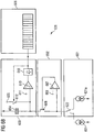
- the sensor electrode 601 it is particularly advantageous in the circuit arrangement 620 shown in Fig. 6B for the sensor electrode 601 to be optionally able to be decoupled from the first circuit unit 602 and to be able to be coupled instead to the calibration device 621, the main component of which is a reference current source 621A.
- the circuit arrangement 620 can be calibrated by means of a calibration current generated by the calibration device 621. This is advantageous in particular when the exact value of the capacitance C of the first capacitor 604 is not known.
- the parasitic capacitances of the circuit arrangement 620 which can be calculated only with significant effort or which cannot be calculated exactly at all, contribute substantially to the overall capacitance of the storage node and influence the resulting output frequency in which the current signal to be detected is coded significantly.
- Offset voltages, in particular of the second comparator 610 in the current-to-frequency converter, and possible leakage currents or stay currents may also directly influence the output frequency to be detected.
- the calibration device 621 preferably comprises a connectible reference current source 621A that provides a known sensor current or increases or reduces said current by a specified amount when the reference current source 621A is connected in parallel with the sensor electrode 601.
- the frequency change resulting from the connection is then used for calibrating the circuit arrangement 620.
- Calibration of this kind may be carried out in particular before an analyte is applied on or to the sensor electrode 601. In this case, the sensor electrode 601 does not provide any signal current originating from sensor events, and the output frequency is determined from the reference current of the reference current source 621A.
- the selective connection of either the sensor electrode 601 or the calibration device 621 to the first circuit unit 602 is preferably achieved by means of a further switch 622.
- the switch 622 can preferably be switched in such a way that in the operating mode shown in Fig. 6B the calibration device 621 is connected to the second circuit unit 602, whereas in the operating mode shown in Fig. 6B the sensor electrode 601 is not connected to the first circuit unit 602.
- the sensor electrode 601 is connected to the first circuit unit 602
- the calibration device 621 is not connected to the first circuit unit 602.
- Fig. 7 schematically shows an embodiment of the present invention.
- the same reference signs as those in the embodiments according to Fig. 6A to 6B are used, it being possible for a corresponding structure, corresponding properties and corresponding advantages to be achieved, even if repeated description thereof is omitted.
- reference is made to the above explanations regarding Fig. 6A and 6B and in addition also to the explanations regarding Fig. 1 to 5 with respect to further functions, features and properties of the circuit arrangement 100 described therein and/or of the structure and the functioning of the sensor electrode 101, which are in principle also applicable to or implementable on the corresponding components of the example in Fig. 6A and 6B and the embodiment explained in the following. Therefore, in the following only substantial differences and developments are explained in detail.
- the sensor electrode 601 is implemented as what is known as an interdigital electrode 601.
- the sensor electrode 601 comprises finger-like strip conductors 601A.
- the finger-like strip conductors 601A may be electrically or galvanically interconnected or coupled with each other by means of a group / common line or wiring 601 B.
- the sensor electrode 601 is preferably formed by the strip conductors 601A and the group line or wiring 601 B.
- the strip conductors 601A and the group line or wiring 601 B thus preferably comprise a conductive surface on which capture molecules 105 can be immobilised.
- the sensor electrode 601, strip conductors 601A and/or the group line or wiring 601B is/are preferably electrically connected to the first circuit unit 602 by means of a connection line or wiring 601C.
- the connection line or wiring 601C preferably connects the sensor electrode 601 to an input of the first circuit unit 602.
- the finger-like strip conductors 601A, 601'A particularly preferably mutually engage in a finger-like manner such that a finger-like strip conductor 601 A of the sensor electrode 601 runs or extends so as to be substantially in parallel with a finger-like strip conductor 601'A of the counterelectrode 601' in each case.
- the strip conductors 601A, 601'A mutually engage in a finger-like manner, by means of which the interdigital structure can be formed.
- the sensor electrode 601 is electrically coupled or connected to the first circuit unit 602. This is preferably carried out by means of the connection line or wiring 601C.
- the connection line or wiring 601C is continuously and/or directly connected or coupled to the first circuit unit 602. Therefore, unlike in the example according to Fig. 6B , no switch 622 is arranged between the sensor electrode 601 and the first circuit unit 602 such that the sensor electrode 601 can be decoupled from the first circuit unit 602.
- a switch 622 may also be provided, as explained in connection with Fig. 6B . Said switch 622 would then be capable of selectively (alternately) connecting the first circuit unit 602 either to the sensor electrode 601 or to a reference current source 621B.
- the sensor electrode 601 preferably forms an electrically conductive surface of a biosensor.
- the strip conductors 601 A and/or the group line or wiring 601B form a surface that is electrically conductive towards the surroundings, while the remaining circuit arrangement 600 may be integrated at least substantially below the sensor electrode 601 and/or in a semiconductor material.
- the circuit arrangement 600 is therefore particularly preferably what is known as a system-on-chip (SoC) or a system-in-package (SiP).
- the circuit arrangement 600 further comprises a second circuit unit 603 and a first capacitor 604.
- the second circuit unit 603 is preferably configured such that, if the electrical potential of the first capacitor 604 is outside a second reference range, said unit detects this event and brings the first capacitor 604 to a first electrical reference potential.
- a connectible reference current source 621B is preferably provided at the sensor electrode 601. Said reference current source 621B can impress a reference current R into the sensor electrode 601 and/or the first circuit unit 602.
- the reference current R may have a positive or negative sign, and so the reference current source 621B can generate a reference current R into the sensor electrode 601 or out of the sensor electrode 601.
- a reference current R is preferably a direct current, i.e. a current that is at least substantially constant in portions.
- the reference current R may also comprise an alternating component or may be an alternating signal. This can be used to test the inertia of the circuit arrangement 600 by means of determining the temporal spacing at which a measurement result M of the circuit arrangement 600 follows the reference current R.
- the reference current source 621B is preferably designed to provide a known reference current R or to increase or reduce the sensor current S that flows from the sensor electrode 601 into the first circuit unit 602 by a specific, preferably known, amount. This preferably occurs when the reference current source 621B is connected to the sensor electrode 601.
- the reference current source 621B can be connected to the sensor electrode 601 such that a reference current R is injected (impressed) into the sensor electrode 601. In the case of an intact sensor electrode 601, the reference current R is conducted into the first circuit unit 602 as the sensor current S.
- the reference current source 621B may be directly connected or connectable to the input of the first circuit unit 602 or to the connection line or wiring 601C, the sensor electrode 601 preferably not being separated from or being inseparable from the first circuit unit 602 (not shown).
- a switch 622 may also be provided, which switch separates the sensor electrode 601 from the first circuit unit 602 when the first circuit unit 602 is connected to the reference current source 621B directly or via the connection line or wiring 601C.
- a current source in particular the reference current source 621B, is connected in parallel in particular when it is coupled to the sensor electrode 601 in such a way that a (positive or negative) current is impressed into the first circuit unit 602.
- the reference current source 621B is connected in parallel with regard to a (virtual) ground or a reference potential for the sensor electrode 601.
- the reference point may also be a small signal ground or the like.
- the circuit arrangement 600 is designed and the reference current source 621B can be operationally adjusted or set such that the reference current source 621B injects into the sensor electrode 601 either no reference current R or a first reference current R having a first current strength / amperage and at least one second reference current R having a second current strength / amperage that is different from the first current strength / amperage.
- the reference current source 621 B may be continuously adjustable.
- the reference current source 621B is adjustable in steps, preferably having at least two steps, in which the reference current source 621B delivers or injects into the sensor electrode 601 and/or the first circuit unit 602 different reference currents R, i.e. reference currents R of different current strengths.
- "Injection" of the reference current R generated by the reference current source 621B means in particular that the reference current source 621B is electrically coupled to the sensor electrode 601 and/or to the first circuit unit 602, in particular is (galvanically) connected thereto, such that the reference current R that is provided by the reference current source 621B is impressed or fed into the conductive structure, i.e. in particular into the strip conductors 601A, the group line or wiring 601 B and/or into the connection line or wiring 601C.
- the circuit arrangement 600 generates the measurement result M in a manner dependent on the sensor current S, i.e. the current that flows from the sensor electrode 601 into the first circuit unit 602, and particularly preferably in the form of a frequency, as explained above in particular in connection with Fig. 6A and 6B . Therefore, in the case of a specific sensor current S, a specific measurement result M is to be anticipated or expected, in particular in a manner dependent on the capacitance of the capacitor 604.
- the circuit arrangement 600 can be deactivated or disregarded for controlled or normal operation.
- controlled or normal operation is the use as a sensor, in particular a biosensor, preferably when the reference current source 621B is deactivated or electrically decoupled.
- an advantage of the adjustable reference current source 621B is that it is possible to achieve twice the certainty with regard to functional testing because it is possible to monitor measurement results M for different sensor currents S generated by the reference current source 621B.
- target values or target value ranges can be specified in each case for the reference currents R of different current strengths that are or can be injected by the reference current source 621B, in which target values or target value ranges the measurement result M is anticipated or expected to be in the case of proper functioning. If the measured value M is outside the defined range when one of the different reference currents R is injected, a fault can be identified and/or handled, in particular by deactivating the circuit arrangement 600.
- the circuit arrangement 600 can be calibrated or able to be calibrated in this manner, i.e. by determining at least two measured values M on the basis of at least two different reference currents R that have been impressed or injected by the reference current source 621B.
- the reference current/measurement result pairs it is possible to create reference current/measurement result pairs and/or to assign the different reference currents R to the different measurement results M. Owing to the fact that the reference currents R are known in advance, it is possible, conversely, to assign the measurement results M to the respective reference currents R.
- This assignment or assignment function that is or can be determined on this basis may be used in order to reliably conclude, during subsequent controlled or normal operation (when the reference current source 621B is decoupled), the sensor currents S from measurement results M generated by a sample.
- an assignment function and/or correction function can be generated with the reference current/measurement result pairs, by means of which it is then possible to conclude the sensor currents S from the measurement results M. In this way, the relevant sensor current S can be calculated or corrected using the measurement results M.
- different reference currents R currents of different current strengths
- measurement results M that correspond to the known reference currents R can be generated and fault control, fault correction and/or calibration of the circuit arrangement 600 can be carried out using the sensor current/measurement result value pairs that result herefrom.
- At least two different current sources 623, 624 are provided, which sources together form the current source 621 B and/or the reference current R.
- at least one of the current sources 623, 624 is activatable and/or deactivatable.
- the current sources 623, 624 are connected in parallel, such that the currents generated by said current sources 623, 624 add up to the reference current R.
- the reference current source 621B may generate a reference current R that is zero, or that corresponds to the current strength of the first current source 623, the current strength of the second current source 624 or the current strength of the sum of that provided by the current sources 623, 624.
- both current sources 623, 624 are switchable by means of switches 625, 626.
- the current sources 623, 624 are, respectively, connected in series with the switches 625, 626. This can be achieved in practice in that the current sources 623, 624 have an internal resistance (not shown). However, the current sources 623, 624 can also be designed so as to be switchable or activatable and/or deactivatable in another manner.
- the current sources 623, 624 form a switchable and/or adjustable reference current source 621 B.
- the adjustability of the reference current source 621 B can also be achieved in another manner, however.
- the (relevant) current source 623, 624 may be formed as a current mirror or may comprise a current mirror. However, other solutions are also conceivable here.
- the reference current source 621B is preferably adjustable in specified or predefined steps. This can be achieved in the example shown by selectively activating none, just one, or both of the current sources 623, 624. However, other solutions for stepped adjustability of the reference current source 621 B are also possible here.
- the reference current source 621B preferably generates a reference current R that is injected into the sensor electrode 601 and/or the connection line or wiring 601C and flows as the sensor current S into the first circuit unit 602 (as measurement current).
- the circuit arrangement 600 is preferably capable of determining a short circuit of the sensor electrode 601 to another sensor electrode or a counterelectrode 601'.
- the circuit arrangement 600 is designed for determining a connection problem between the sensor electrode 601 and the first circuit unit 602 on the basis of the measurement results M.
- This can be achieved for example in that the measurement result M determined by the circuit arrangement 600 deviates from an anticipated or expected value or target value/region in the event of a specified, predetermined or known reference current R injected into the sensor electrode 601.
- a target value comparison with the measured measurement result M may be carried out, and a fault can be detected in the event of the measurement result M deviating from the target value or from a target value range.
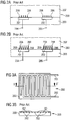
- Fig. 8 shows, by way of example, a temporal progression of the reference current R and of the measurement result M, plotted over the same time T in each case.
- a first reference current R1 is injected into the sensor electrode 601, the connection line or wiring 601C and/or the input of the first circuit unit 602.
- the first reference current R1 having a first current strength that is different from 0 is generated by activating just one of the current sources 623, 624 or by deactivating the other current source 623, 624.
- a corresponding first measurement result M1 can be determined, which result preferably deviates from the offset (measured value MO).
- the circuit arrangement 600 does not measure a reference current R injected into the sensor electrode 601. This is indicated in Fig. 8 by the dashed line F1.
- the reference currents R1, R2 differ at least, preferably exactly or only, in terms of the current strength thereof.
- a measurement result M2 corresponding to the reference current R2 is or can be determined.
- Said reference current R2 can be generated by a current source 623, 624 that is different from the current source 623, 624 that generates the first reference current R1.
- one current source 623 can generate the first reference current R1 and the other current source 624 can generate the second reference current R2.
- a third reference current R3 to which a third measurement result M3 corresponds is injected after the time point T3.
- the third reference current R3 preferably deviates from the reference currents R1 and R2 (in terms of the current strength).
- the reference current R3 is generated by interconnecting the respectively active current sources 623, 624, such that the currents thereof are added together.
- the reference currents R0, R1, R2, R3 preferably each differ from one another, in particular in terms of the current strength thereof. Correspondingly, this preferably also applies to the measurement results M0, M1, M2, M3.
- a dashed line F1 is shown, according to which the measurement result M0 is always determined in a manner independent of the reference current. This is the case if the reference current R injected into the sensor electrode 601 does not have any effect on the measurement result M, for example owing to a break U1, indicated in Fig. 7 , of or in the sensor electrode 601, in particular of one or more of the strip conductors 601A, the group line or wiring 601B and/or on account of a break U2, also indicated in Fig. 7 , of the connection line or wiring 601C.
- the fault line F2 is also shown as a dashed line in the diagram or graph according to Fig. 8 , which line indicates a progression of the measurement result M when the sensor electrode 601 is short circuited to a sensor electrode 601' of another circuit arrangement 600'. This is indicated in Fig. 7 by the dashed lines K1, K2.
- the reference current R can at least substantially drain, via the short circuit in question, into and away via the counterelectrode 601', such that a measurement result M as indicated by the dashed line F1 can arise.
- the injected reference current R is optionally divided over two inputs of the relevant circuit arrangements 600, 600', such that the measurement result M in each case is smaller than anticipated/expected, in particular proportionally to the anticipated or expected measurement result M. This is indicated by the second fault line F2.
- a short circuit of the sensor electrode 601 to the sensor electrode 601' of another circuit arrangement 600' is indicated in particular if the anticipated or expected difference between the measurement result M0 without any injected reference current R and the measurement result M1, M2, M3 when a reference current R1, R2, R3 is injected corresponds to approximately half of the anticipated or expected value or target value. Accordingly, the measurement result M can be analysed with respect to behaviour of this kind, and if necessary the corresponding fault can be detected.
- the circuit arrangement 600 is preferably designed to generated corresponding reference currents R and to evaluate measurement results M generated in this case in order to determine faults and/or carry out calibration.
- the reference current source 621B can preferably be electrically coupled to the sensor electrode 601 by means of one or more switches 627, 628.
- the reference current source 621B can preferably be selectively coupled to a first portion 601D and to another, second portion 601E of the sensor electrode 601.
- a plurality of switches 627, 628 may be provided for this purpose.
- a first switch 627 connects the reference current source 621B to the first portion 601D and/or a second switch 628 connects the reference current source 621B to the second portion 601E.
- the first portion 601D is located in the region of the interdigital structure, in particular in the region of the strip conductors 601A and/or of the group line or wiring 601 B.
- the second portion 601E is located in the region of the connection line or wiring 601C by means of which the strip conductors 601 A and/or the group line 601 B or wiring is/are connected to the first circuit unit 602.
- the first portion 601D is preferably located in the region of the sensor electrode 601, the conductive surface of which directly functions as biosensor, while the second portion 601E is preferably directly connected to the first circuit unit 602 by means of the connection line or wiring 601C.
- the second portion 601E can thus be formed by the input of the first circuit unit 602.
- the sensor electrode 601 In the initial state, i.e. without any molecules immobilised on the surface, or in any case without a sample being in contact with the sensor electrode 601, the sensor electrode 601 preferably forms an open node via which no (direct) currents can drain away. It should therefore be assumed, in the case of correct functioning, that the reference current R passes the sensor electrode 601 unchanged and flows or is fed into the first circuit unit 602 as the sensor current S. This applies in any case for reference currents R that are provided so as to be at least substantially constant or as a direct current.
- Measurement results M are preferably generated when the reference current R is alternatively injected on the one hand into the first portion 601D and on the other hand into the second portion 601E of the sensor electrode 601. Provided that the reference current R is the same, i.e. is of the same current strength, it should therefore be anticipated or expected that the same measurement result M is generated. If this is not the case, i.e. if the measurement result M is changed in a not insignificant manner depending on the portion 601D, 601E into which the reference current R is injected, it is possible to conclude that there is a contact problem between the sensor electrode 601 and the first circuit unit 602. Fault handling, which may follow, can lead to or be used for deactivation of the tested circuit arrangement 600.
- the second portion 601E is provided in the region of the connection line or wiring 601C and/or at the input of the first circuit unit 602.
- the second switch 626 can be used to connect the reference current source 621B to the second portion 601E. In this way, the reference current R can be injected into the second portion 601E by the reference current source 621B.
- other solutions are also possible here.
- the reference current source 621B is then adjusted or set so as to inject into the sensor electrode 601 no current at a time point T0, a first reference current R having a first current strength at another time point T1, and at least one second reference current R that is different from the first and has a second current strength that is different from the first current strength at yet another time point T2.
- the measurement results M determined and dependent on the different injected reference currents R, in particular as described above, can be used to determine contact problems, short circuits and/or proper functioning or linearity of the circuit arrangement 600, and/or to carry out calibration, a correction function or another item of correction information for correcting measurement results M preferably being determined and preferably being used in the subsequent measurement using a sample.
- the measurement result M is determined depending on the injected reference current R, in particular in the form of a frequency that corresponds to pulses that were or can be generated in the manner described above in connection with Fig. 6A and 6B .
- a reference current R is injected into each of the different portions 601D, 601E of the sensor electrode 601, preferably in succession.
- the first portion 601D is preferably part of the interdigital structure formed by the sensor electrode 601
- the second portion 601E is preferably provided in the region of the connection line or wiring 601C, i.e. a connection between the interdigital structure and the first circuit unit 602.
- the measurement results M that are generated or can be determined when the reference current R is injected into the different portions 601D, 601E are preferably compared with one another. If said results deviate (not insignificantly) from one another, a contact problem inside the sensor electrode 601 can be detected. Accordingly, fault handling may be carried out in the event of fault identification, for example by deactivating the (in this case tested) circuit arrangement 600.
- the aspects of the present invention can be advantageously combined with one another. It is thus possible to combine and/or synchronise the switches 625, 626 and 627, 628 with one another such that, on the one hand, (preferably the same) reference current R is injected into the different portions 601D, 601E of the sensor electrode 601, and in addition, but only optionally in both portions 601D, 601E, different reference currents R (of different current strengths) are generated by the reference current source 621B and injected into the sensor electrode 601.
- the measurement results M that are generated or can be determined overall in this case can be used for a functional test as well as for a short circuit test and for calibration. It is thus possible to quickly achieve a high degree of functional reliability and reliability of the measurement results M by means of just a few test measurements that are easy to carry out.
- the controller 629 is preferably designed to activate, deactivate, connect individually or combine together one or more current sources 623, 624, in particular by means of the switches 625, 626, such that the currents are added together.
- the controller 629 is designed to control the reference current source 621B such that said source is or can be connected either to the first portion 601D or to the second portion 601E of the sensor electrode 601.
- the controller 629 controls one or more of the switches 627, 628 such that the reference current R is injected into the first portion 601D or into the second portion 601E.
- the controller 629 can control the switches 627, 628 such that a connection is established or broken, such that the reference current R is injected either into the first portion 601D or into the second portion 601E.
- the reference current R is injected into both portions 601D, 601E simultaneously.
- the switch 627 is replaced by a through-connection, and only the switch 628 is controlled. If the measurement results M deviate depending on whether the reference current R is injected only into the first portion 601D or also into the second portion 601E, a fault, for example a contact problem, can therefore be identified.
- the controller 629 is preferably designed to control the current sources 623, 624 and/or switches 625, 626, 627, 628 in such a way that the proposed method is carried out.
- the controller 629 can receive the measurement result M and compare said result with a specification or target.
- the specification or target may result from or correspond to control commands that the controller 629 uses to control the reference current source 621B.
Landscapes
- Physics & Mathematics (AREA)
- General Physics & Mathematics (AREA)
- Engineering & Computer Science (AREA)
- General Engineering & Computer Science (AREA)
- Electromagnetism (AREA)
- Investigating Or Analyzing Materials By The Use Of Electric Means (AREA)
Claims (15)
- Procédé pour tester et/ou étalonner un agencement de circuit (600) comprenant une électrode de capteur (601), une première unité de circuit (602) qui est couplée électriquement à l'électrode de capteur (601), et une seconde unité de circuit (603) qui comprend un premier condensateur (604) ;
la première unité de circuit (602) étant configurée de manière à maintenir le potentiel électrique de l'électrode de capteur (601) dans une première plage de référence spécifiable autour d'un potentiel électrique cible spécifiable au moyen du premier condensateur (604) et l'électrode de capteur (601) étant couplée de telle sorte qu'une adaptation du potentiel électrique est rendue possible ;
la deuxième unité de circuit (603) étant configurée de telle sorte que, si le potentiel électrique du premier condensateur (604) est en dehors d'une deuxième plage de référence, ladite unité détecte cet événement et amène le premier condensateur (604) à un premier potentiel électrique de référence, et
une source de courant de référence connectable (621B) étant prévue à l'électrode de capteur (601), laquelle source fournit un courant de référence connu (R) lorsque la source de courant de référence (621B) est connectée à l'électrode de capteur (601), de sorte que le courant de référence (R) est injecté dans l'électrode de capteur (601) et/ou dans ladite unité de circuit (602),
caractérisé
en ce que la source de courant de référence (621B) est ajustée de manière à n'injecter dans l'électrode de capteur (601) aucun courant ainsi qu'un premier courant de référence (R) ayant une première intensité de courant et au moins un deuxième courant de référence (R) ayant une deuxième intensité de courant qui est différente de la première intensité de courant ; et/ou
en ce qu'un résultat de mesure (M) est généré et analysé en fonction du courant de référence (R) injecté dans l'électrode de capteur (601) et/ou dans une électrode de capteur (601') d'un autre agencement de circuit (600') afin de déterminer un court-circuit de l'électrode de capteur (601) et/ou un problème de connexion entre l'électrode de capteur (601) et la première unité de circuit (602) ; et/ou
en ce que la source de courant de référence (621B) injecte le courant de référence (R) d'une part dans une première partie (601D) et d'autre part dans une autre seconde partie (601E) de l'électrode de capteur (601), de préférence la première partie (601D) faisant partie d'une structure interdigitale et la seconde partie (601E) étant prévue dans la région d'une ligne de connexion ou d'un câblage (601C) entre la structure interdigitale et la première unité de circuit (602). - Procédé selon la revendication 1, caractérisé en ce que la source de courant de référence (621B) est ajustée par étapes prédéfinies, de sorte que la source de courant de référence (621B) injecte des courants de référence (R) spécifiques et prédéfinis dans l'électrode de capteur (601).
- Procédé selon la revendication 1 ou 2, caractérisé en ce que l'agencement de circuit (600) génère un résultat de mesure (M), en particulier une fréquence, en fonction du courant de référence (R) injecté dans l'électrode de capteur (601) et/ou des événements détectés provoqués par celui-ci.
- Procédé selon la revendication 3, caractérisé en ce que, pour un test de la linéarité, plusieurs courants de référence (R) différents, respectivement connus, sont injectés dans l'électrode de capteur (601) par la source de courant de référence (621B), une linéarité ou un écart par rapport à une dépendance proportionnelle des résultats de mesure (M) du courant de référence injecté global (R) étant déterminable ou déterminé sur la base des résultats de mesure (M).
- Procédé selon la revendication 3 ou 4, caractérisé en ce que le résultat de mesure (M) déterminé lors de la coupure de la source de courant de référence (621B) est utilisé pour identifier un court-circuit, en particulier sur une électrode adjacente à l'électrode de capteur (601) ; et/ou en ce que le résultat de mesure (M) déterminé lors de la mise en marche de la source de courant de référence (621B) est utilisé pour vérifier la mise en contact et/ou la formation d'une structure interdigitale.
- Procédé selon l'une quelconque des revendications 3 à 5, caractérisé en ce que plusieurs courants de référence (R) différents, respectivement connus, sont injectés dans l'électrode de capteur (601) par la source de courant de référence (621B), des résultats de mesure (M) qui correspondent aux courants de référence (R) sont déterminés par l'agencement de circuit (600), une comparaison des résultats de mesure (M) avec des valeurs de consigne est effectuée, et un calibrage de l'agencement de circuit (600) pour corriger les résultats de mesure (M) est effectué sur la base de ladite comparaison, de préférence lorsque, en termes de fonctionnement, les sources de courant sont désactivées pendant un processus de mesure.
- Procédé selon l'une quelconque des revendications 3 à 6, caractérisé en ce que le résultat de mesure (M) dans le cas d'un courant de référence (R) injecté dans la première partie (601D) est comparé au résultat de mesure (M) dans le cas d'un courant de référence (R) injecté dans la deuxième partie (601E) afin de vérifier la mise en contact d'une structure interdigitale, en particulier en ce que, en cas de courants de référence (R) injectés identiques dans les différentes parties (601D, 601E), un écart des résultats de mesure (M) au-dessus d'un seuil est classé comme indicateur d'une mise en contact défectueuse, de sorte que l'agencement de circuit (600) peut être désactivé ou ignoré pendant une évaluation.
- Procédé selon l'une quelconque des revendications 3 à 7, caractérisé en ce qu'il est prévu une pluralité d'agencements de circuit (600) dont les électrodes de capteur (601, 601') forment une structure interdigitale commune, et en ce qu'un courant de référence (R) est injecté dans l'électrode de capteur (601) de l'un des agencements de circuit (600) par la source de courant de référence (621B) et le résultat de mesure (M) de l'autre des agencements de circuit (600) est utilisé pour contrôler les agencements de circuit (600) quant à une isolation ou un court-circuit entre les électrodes de capteur (601, 601').
- Agencement de circuit (600) ayant une électrode de capteur (601), une première unité de circuit (602) qui est couplée électriquement à l'électrode de capteur (601), et une seconde unité de circuit (603) qui comprend un premier condensateur (604) ;
la première unité de circuit (602) étant configurée de manière à maintenir le potentiel électrique de l'électrode de capteur (601) dans une première plage de référence spécifiable autour d'un potentiel électrique cible spécifiable au moyen du premier condensateur (604) et l'électrode de capteur (601) étant couplée de telle sorte qu'une adaptation du potentiel électrique est rendue possible ;
la deuxième unité de circuit (603) étant configurée de telle sorte que, si le potentiel électrique du premier condensateur (604) est en dehors d'une deuxième plage de référence, ladite unité détecte cet événement et amène le premier condensateur (604) à un premier potentiel électrique de référence, et
une source de courant de référence connectable (621B) étant prévue à l'électrode de capteur (601), laquelle source fournit un courant de référence connu (R) lorsque la source de courant de référence (621B) est connectée à l'électrode de capteur (601), de sorte que le courant de référence (R) est injecté dans l'électrode de capteur (601) et/ou dans ladite unité de circuit (602),
caractérisé
en ce que l'agencement de circuit (600) est conçu et la source de courant de référence (621B) est ajustable de telle sorte qu'elle n'injecte dans l'électrode de capteur (601) aucun courant de référence (R) ainsi qu'un premier courant de référence (R) ayant une première intensité de courant et au moins un deuxième courant de référence (R) ayant une deuxième intensité de courant différente de la première intensité de courant ; et/ou
en ce que l'agencement de circuit (600) est conçu pour déterminer l'énergie électrique transmise par l'électrode de capteur (601) à la première unité de circuit (602), aussi bien lorsque la source de courant de référence (621B) est désactivée que lorsqu'elle est connectée, en tant que résultats de mesure (M), lesdits résultats de mesure étant analysés en fonction du courant de référence (R) injecté dans l'électrode de capteur afin de déterminer un court-circuit de l'électrode de capteur (601) et/ou un problème de connexion entre l'électrode de capteur (601) et la première unité de circuit (602) ; et/ou
en ce que la source de courant de référence (621B) est connectable sélectivement à une première partie (601D) et à une autre, seconde partie (601E) de l'électrode de capteur (601), de sorte que le courant de référence (R) est injecté dans la première partie (601D) ou dans la seconde partie (601E), la première partie (601D) faisant partie d'une structure interdigitale et la seconde partie (601E) étant prévue dans la région d'une ligne de connexion ou d'un câblage (601C) entre la structure interdigitale et la première unité de circuit (603). - Agencement de circuit selon la revendication 9, caractérisé en ce que la source de courant de référence (621B) est ajustable par étapes prédéfinies ou spécifiées.
- Agencement de circuit selon la revendication 9 ou 10, caractérisé en ce que la source de courant de référence (621B) comprend au moins deux sources de courant (623, 624) qui peuvent être activées et désactivées séparément l'une de l'autre et qui, respectivement, n'injectent aucun courant de référence (R) à l'état désactivé et injectent un courant de référence (R) prédéfini ou spécifié à l'état activé.
- Agencement de circuit selon la revendication 11, caractérisé en ce que les sources de courant (623, 624) sont interconnectées de telle sorte que leurs courants de référence (R) sont injectés ou injectables dans l'électrode de capteur (601) de manière additionnée de manière à former le courant de référence (R).
- Agencement de circuit selon la revendication 11 ou 12, caractérisé en ce que les sources de courant (623, 624) comprennent un circuit de stabilisation pour générer un courant de référence (R) qui est au moins sensiblement indépendant d'une tension d'alimentation, de préférence au moyen d'un miroir de courant et/ou d'un circuit de référence à bande interdite.
- Agencement de circuit selon l'une quelconque des revendications 11 à 13, caractérisé en ce que l'agencement de circuit (600) est conçu pour générer un résultat de mesure (M), en particulier une fréquence, sur la base du courant de référence (R) injecté dans l'électrode de capteur (601).
- Agencement de circuit selon la revendication 14, caractérisé en ce que le résultat de mesure (M) peut être déterminé au moyen d'un élément de comptage (606) qui est couplé électriquement à la deuxième unité de circuit (603) et qui est configuré pour compter le nombre et/ou la séquence temporelle des résultats détectés, de préférence le résultat de mesure (M) ayant ou étant formé par la valeur de comptage ou une fréquence déterminée par celle-ci.
Applications Claiming Priority (2)
| Application Number | Priority Date | Filing Date | Title |
|---|---|---|---|
| EP17020448 | 2017-09-29 | ||
| PCT/EP2018/076209 WO2019063663A1 (fr) | 2017-09-29 | 2018-09-27 | Test et étalonnage d'un agencement de circuit |
Publications (2)
| Publication Number | Publication Date |
|---|---|
| EP3673274A1 EP3673274A1 (fr) | 2020-07-01 |
| EP3673274B1 true EP3673274B1 (fr) | 2021-09-01 |
Family
ID=60019665
Family Applications (1)
| Application Number | Title | Priority Date | Filing Date |
|---|---|---|---|
| EP18782911.4A Active EP3673274B1 (fr) | 2017-09-29 | 2018-09-27 | Essai et étalonnage d'un agencement de circuit |
Country Status (8)
| Country | Link |
|---|---|
| US (1) | US10921368B2 (fr) |
| EP (1) | EP3673274B1 (fr) |
| JP (1) | JP2020535422A (fr) |
| KR (1) | KR20200064076A (fr) |
| CN (1) | CN111108398A (fr) |
| BR (1) | BR112020006261A2 (fr) |
| CA (1) | CA3074169A1 (fr) |
| WO (1) | WO2019063663A1 (fr) |
Family Cites Families (35)
| Publication number | Priority date | Publication date | Assignee | Title |
|---|---|---|---|---|
| US3711779A (en) | 1970-11-17 | 1973-01-16 | Instrumentation Specialties Co | Apparatus for determining and characterizing the slopes of time-varying signals |
| US4199728A (en) | 1978-08-21 | 1980-04-22 | Innovative Medical Systems, Corp. | Slope detector |
| DE3034124A1 (de) * | 1980-09-11 | 1982-04-22 | Knorr-Bremse GmbH, 8000 München | Schaltungsanordnung zur digitalen messung einer zeitveraenderlichen groesse |
| JP3372866B2 (ja) * | 1998-04-08 | 2003-02-04 | 三基システムエンジニアリング株式会社 | 封止破壊検知装置 |
| JP4268266B2 (ja) * | 1999-06-10 | 2009-05-27 | 日本特殊陶業株式会社 | 配線基板の導体層形成工程の検査方法 |
| CN2436941Y (zh) * | 2000-07-27 | 2001-06-27 | 李坤 | 电信线路故障检测仪 |
| EP1278073A1 (fr) * | 2001-07-20 | 2003-01-22 | ENSECO GmbH | Dispositif de mesure d'un courant électrique qui circule dans au moins un conducteur électrique et méthode de correction d'erreurs dans ledit dispositif |
| DE10203996A1 (de) * | 2002-02-01 | 2003-08-21 | Infineon Technologies Ag | Schaltkreis-Anordnung, Redox-Recycling-Sensor, Sensor-Anordnung und Verfahren zum Verarbeiten eines über eine Sensor-Elektrode bereitgestellten Stromsignals |
| DE10204652B4 (de) * | 2002-02-05 | 2004-07-22 | Infineon Technologies Ag | Schaltkreis-Anordnung, elektrochemischer Sensor, Sensor-Anordnung und Verfahren zum Verarbeiten eines über eine Sensor-Elektrode bereitgestellten Stromsignals |
| DE10321490B3 (de) * | 2002-02-05 | 2004-10-14 | Infineon Technologies Ag | Schaltkreis-Anordnung, elektrochemischer Sensor, Sensor-Anordnung und Verfahren zum Verarbeiten eines über eine Sensor-Elektrode bereitgestellten Stromsignals |
| DE10221885B4 (de) | 2002-05-16 | 2005-12-29 | Infineon Technologies Ag | Sensor-Einheit, Sensor-Anordnung und Verfahren zum Betreiben einer Sensor-Einheit |
| DE10397018A5 (de) * | 2002-07-02 | 2015-05-28 | Panasonic Healthcare Holdings Co., Ltd. | Biosensor, Biosensorchip und Biosensoreinrichtung |
| EP1636599B1 (fr) | 2003-05-13 | 2007-05-02 | Siemens Aktiengesellschaft | Ensemble circuit de commutation pour la stabilisation de potentiel sur un biocapteur et la numerisation du courant de mesure |
| CN1281924C (zh) * | 2004-03-25 | 2006-10-25 | 浙江大学 | 基于电压频率变换原理的低成本高精度测量方法 |
| DE102004025580A1 (de) | 2004-05-25 | 2005-12-22 | Infineon Technologies Ag | Sensor-Anordnung, Sensor-Array und Verfahren zum Herstellen einer Sensor-Anordnung |
| DE102004059960A1 (de) * | 2004-12-13 | 2006-06-22 | Bourns, Inc., Riverside | Schaltungsanordnung zur Messung eines elektrischen Stromes |
| CN1818681A (zh) * | 2005-01-21 | 2006-08-16 | 三洋电机株式会社 | 电压-频率转换装置及其基准电压变更方法 |
| GB2436619B (en) * | 2005-12-19 | 2010-10-06 | Toumaz Technology Ltd | Sensor circuits |
| TWI296457B (en) * | 2006-01-18 | 2008-05-01 | Univ Yuan Ze | High-performance power conditioner for solar photovoltaic system |
| AT503742B8 (de) * | 2006-05-15 | 2011-08-15 | Arc Austrian Res Centers Gmbh | Elektronische biosensoranordnung |
| CN101281191B (zh) * | 2007-11-14 | 2012-10-10 | 石西增 | 一种对磁敏传感生物芯片进行自动测量的仪器 |
| WO2009082706A1 (fr) * | 2007-12-21 | 2009-07-02 | The Trustees Of Columbia University In The City Of New York | Réseau de capteur cmos actif pour la détection biomoléculaire électrochimique |
| EP2346402B1 (fr) * | 2008-10-16 | 2015-05-13 | Koninklijke Philips N.V. | Circuit et procédé de mesure d'impédance |
| FR2956212B1 (fr) * | 2010-02-08 | 2012-03-09 | Schneider Electric Ind Sas | Dispositif et procede de comptage d'energie electrique |
| US20110208435A1 (en) * | 2010-02-25 | 2011-08-25 | Lifescan Scotland Ltd. | Capacitance detection in electrochemical assays |
| JP5201194B2 (ja) * | 2010-10-28 | 2013-06-05 | 株式会社デンソー | 粒子状物質検出装置及び粒子状物質検出素子の製造方法 |
| CN102299752B (zh) * | 2011-05-27 | 2013-12-11 | 上海信朴臻微电子有限公司 | 预校准射频功率检测器 |
| CN102411117B (zh) * | 2011-08-09 | 2014-07-02 | 中国电力科学研究院 | 一种基于分布式智能多重校准的配电网短路故障定位方法 |
| JP2013134078A (ja) * | 2011-12-26 | 2013-07-08 | Denso Corp | 容量式物理量検出装置 |
| GB2518592B (en) * | 2013-08-06 | 2016-02-24 | Ge Aviat Systems Ltd | Built-in testing of an arc fault/transient detector |
| CN103543323A (zh) * | 2013-11-05 | 2014-01-29 | 云南省计量测试技术研究院 | 大直流充放电设施电流检测装置 |
| CN104635104B (zh) * | 2013-11-14 | 2017-11-24 | 宁波舜宇光电信息有限公司 | 一种摄像模组断路短路自动测试设备及其测试方法 |
| CN203658433U (zh) * | 2013-11-25 | 2014-06-18 | 中国船舶重工集团公司第七一九研究所 | 一种高灵敏度宽量程电流放大变换电路 |
| CN106501617B (zh) * | 2016-12-22 | 2023-05-02 | 华南理工大学 | 介质材料测量件的校准方法、短路校准件、介质材料测量方法及装置 |
| CN106990321A (zh) * | 2017-03-22 | 2017-07-28 | 武汉双微电气股份有限公司 | 基于电压监测的配电线路故障识别装置 |
-
2018
- 2018-09-27 CA CA3074169A patent/CA3074169A1/fr active Pending
- 2018-09-27 EP EP18782911.4A patent/EP3673274B1/fr active Active
- 2018-09-27 JP JP2020517793A patent/JP2020535422A/ja active Pending
- 2018-09-27 US US16/144,445 patent/US10921368B2/en active Active
- 2018-09-27 BR BR112020006261-8A patent/BR112020006261A2/pt not_active Application Discontinuation
- 2018-09-27 CN CN201880061783.0A patent/CN111108398A/zh active Pending
- 2018-09-27 KR KR1020207009048A patent/KR20200064076A/ko not_active Application Discontinuation
- 2018-09-27 WO PCT/EP2018/076209 patent/WO2019063663A1/fr unknown
Also Published As
| Publication number | Publication date |
|---|---|
| WO2019063663A1 (fr) | 2019-04-04 |
| JP2020535422A (ja) | 2020-12-03 |
| US10921368B2 (en) | 2021-02-16 |
| CA3074169A1 (fr) | 2019-04-04 |
| KR20200064076A (ko) | 2020-06-05 |
| BR112020006261A2 (pt) | 2020-10-20 |
| US20190101584A1 (en) | 2019-04-04 |
| CN111108398A (zh) | 2020-05-05 |
| EP3673274A1 (fr) | 2020-07-01 |
Similar Documents
| Publication | Publication Date | Title |
|---|---|---|
| US7914655B2 (en) | Potentiostatic circuit arrangement on a biosensor for digitisation of the measured current | |
| US10663423B2 (en) | System for detecting electrical properties of a molecular complex | |
| US7123029B2 (en) | Circuit arrangement, electrochemical sensor, sensor arrangement, and method for processing a current signal provided via a sensor electrode | |
| US9645106B2 (en) | Monolithically integrated hybridisation sensor assembly and associated production method | |
| CN112924745A (zh) | 纳米孔基因测序微电流检测装置 | |
| US6922081B2 (en) | Electronic circuit, sensor arrangement and method for processing a sensor signal | |
| EP3673274B1 (fr) | Essai et étalonnage d'un agencement de circuit | |
| De Venuto et al. | Design of an integrated low-noise read-out system for DNA capacitive sensors | |
| US20060292708A1 (en) | Circuit arrangement, redox recycling sensor, sensor assembly and a method for processing a current signal provided by a sensor electrode | |
| JP2012159511A (ja) | 化学感応性電界効果トランジスタの少なくとも1つの動作の仕方を監視するための方法および監視装置 | |
| US20070068805A1 (en) | Operating circuit for a biosensor arrangement | |
| DE10321490B3 (de) | Schaltkreis-Anordnung, elektrochemischer Sensor, Sensor-Anordnung und Verfahren zum Verarbeiten eines über eine Sensor-Elektrode bereitgestellten Stromsignals | |
| Fujcik et al. | A Microconductometer Utilizing Bipolar Pulse Method for Electro-Chemical Sensors | |
| CZ20013227A3 (cs) | Způsob stanovení měrné elektrické vodivosti a zařízení pro jeho provádění |
Legal Events
| Date | Code | Title | Description |
|---|---|---|---|
| STAA | Information on the status of an ep patent application or granted ep patent |
Free format text: STATUS: UNKNOWN |
|
| STAA | Information on the status of an ep patent application or granted ep patent |
Free format text: STATUS: THE INTERNATIONAL PUBLICATION HAS BEEN MADE |
|
| PUAI | Public reference made under article 153(3) epc to a published international application that has entered the european phase |
Free format text: ORIGINAL CODE: 0009012 |
|
| STAA | Information on the status of an ep patent application or granted ep patent |
Free format text: STATUS: REQUEST FOR EXAMINATION WAS MADE |
|
| 17P | Request for examination filed |
Effective date: 20200213 |
|
| AK | Designated contracting states |
Kind code of ref document: A1 Designated state(s): AL AT BE BG CH CY CZ DE DK EE ES FI FR GB GR HR HU IE IS IT LI LT LU LV MC MK MT NL NO PL PT RO RS SE SI SK SM TR |
|
| AX | Request for extension of the european patent |
Extension state: BA ME |
|
| DAV | Request for validation of the european patent (deleted) | ||
| DAX | Request for extension of the european patent (deleted) | ||
| GRAP | Despatch of communication of intention to grant a patent |
Free format text: ORIGINAL CODE: EPIDOSNIGR1 |
|
| STAA | Information on the status of an ep patent application or granted ep patent |
Free format text: STATUS: GRANT OF PATENT IS INTENDED |
|
| INTG | Intention to grant announced |
Effective date: 20210319 |
|
| GRAS | Grant fee paid |
Free format text: ORIGINAL CODE: EPIDOSNIGR3 |
|
| GRAA | (expected) grant |
Free format text: ORIGINAL CODE: 0009210 |
|
| STAA | Information on the status of an ep patent application or granted ep patent |
Free format text: STATUS: THE PATENT HAS BEEN GRANTED |
|
| AK | Designated contracting states |
Kind code of ref document: B1 Designated state(s): AL AT BE BG CH CY CZ DE DK EE ES FI FR GB GR HR HU IE IS IT LI LT LU LV MC MK MT NL NO PL PT RO RS SE SI SK SM TR |
|
| REG | Reference to a national code |
Ref country code: GB Ref legal event code: FG4D |
|
| REG | Reference to a national code |
Ref country code: CH Ref legal event code: EP Ref country code: AT Ref legal event code: REF Ref document number: 1426768 Country of ref document: AT Kind code of ref document: T Effective date: 20210915 |
|
| REG | Reference to a national code |
Ref country code: DE Ref legal event code: R096 Ref document number: 602018022976 Country of ref document: DE |
|
| REG | Reference to a national code |
Ref country code: IE Ref legal event code: FG4D |
|
| REG | Reference to a national code |
Ref country code: DK Ref legal event code: T3 Effective date: 20211123 |
|
| REG | Reference to a national code |
Ref country code: LT Ref legal event code: MG9D |
|
| REG | Reference to a national code |
Ref country code: NL Ref legal event code: FP |
|
| PG25 | Lapsed in a contracting state [announced via postgrant information from national office to epo] |
Ref country code: SE Free format text: LAPSE BECAUSE OF FAILURE TO SUBMIT A TRANSLATION OF THE DESCRIPTION OR TO PAY THE FEE WITHIN THE PRESCRIBED TIME-LIMIT Effective date: 20210901 Ref country code: RS Free format text: LAPSE BECAUSE OF FAILURE TO SUBMIT A TRANSLATION OF THE DESCRIPTION OR TO PAY THE FEE WITHIN THE PRESCRIBED TIME-LIMIT Effective date: 20210901 Ref country code: ES Free format text: LAPSE BECAUSE OF FAILURE TO SUBMIT A TRANSLATION OF THE DESCRIPTION OR TO PAY THE FEE WITHIN THE PRESCRIBED TIME-LIMIT Effective date: 20210901 Ref country code: FI Free format text: LAPSE BECAUSE OF FAILURE TO SUBMIT A TRANSLATION OF THE DESCRIPTION OR TO PAY THE FEE WITHIN THE PRESCRIBED TIME-LIMIT Effective date: 20210901 Ref country code: HR Free format text: LAPSE BECAUSE OF FAILURE TO SUBMIT A TRANSLATION OF THE DESCRIPTION OR TO PAY THE FEE WITHIN THE PRESCRIBED TIME-LIMIT Effective date: 20210901 Ref country code: BG Free format text: LAPSE BECAUSE OF FAILURE TO SUBMIT A TRANSLATION OF THE DESCRIPTION OR TO PAY THE FEE WITHIN THE PRESCRIBED TIME-LIMIT Effective date: 20211201 Ref country code: LT Free format text: LAPSE BECAUSE OF FAILURE TO SUBMIT A TRANSLATION OF THE DESCRIPTION OR TO PAY THE FEE WITHIN THE PRESCRIBED TIME-LIMIT Effective date: 20210901 Ref country code: NO Free format text: LAPSE BECAUSE OF FAILURE TO SUBMIT A TRANSLATION OF THE DESCRIPTION OR TO PAY THE FEE WITHIN THE PRESCRIBED TIME-LIMIT Effective date: 20211201 |
|
| PGFP | Annual fee paid to national office [announced via postgrant information from national office to epo] |
Ref country code: DK Payment date: 20211130 Year of fee payment: 4 Ref country code: FR Payment date: 20211129 Year of fee payment: 4 Ref country code: NL Payment date: 20211125 Year of fee payment: 4 |
|
| REG | Reference to a national code |
Ref country code: AT Ref legal event code: MK05 Ref document number: 1426768 Country of ref document: AT Kind code of ref document: T Effective date: 20210901 |
|
| PG25 | Lapsed in a contracting state [announced via postgrant information from national office to epo] |
Ref country code: PL Free format text: LAPSE BECAUSE OF FAILURE TO SUBMIT A TRANSLATION OF THE DESCRIPTION OR TO PAY THE FEE WITHIN THE PRESCRIBED TIME-LIMIT Effective date: 20210901 Ref country code: LV Free format text: LAPSE BECAUSE OF FAILURE TO SUBMIT A TRANSLATION OF THE DESCRIPTION OR TO PAY THE FEE WITHIN THE PRESCRIBED TIME-LIMIT Effective date: 20210901 Ref country code: GR Free format text: LAPSE BECAUSE OF FAILURE TO SUBMIT A TRANSLATION OF THE DESCRIPTION OR TO PAY THE FEE WITHIN THE PRESCRIBED TIME-LIMIT Effective date: 20211202 |
|
| PG25 | Lapsed in a contracting state [announced via postgrant information from national office to epo] |
Ref country code: AT Free format text: LAPSE BECAUSE OF FAILURE TO SUBMIT A TRANSLATION OF THE DESCRIPTION OR TO PAY THE FEE WITHIN THE PRESCRIBED TIME-LIMIT Effective date: 20210901 |
|
| REG | Reference to a national code |
Ref country code: CH Ref legal event code: PL |
|
| REG | Reference to a national code |
Ref country code: BE Ref legal event code: MM Effective date: 20210930 |
|
| PG25 | Lapsed in a contracting state [announced via postgrant information from national office to epo] |
Ref country code: IS Free format text: LAPSE BECAUSE OF FAILURE TO SUBMIT A TRANSLATION OF THE DESCRIPTION OR TO PAY THE FEE WITHIN THE PRESCRIBED TIME-LIMIT Effective date: 20220101 Ref country code: SM Free format text: LAPSE BECAUSE OF FAILURE TO SUBMIT A TRANSLATION OF THE DESCRIPTION OR TO PAY THE FEE WITHIN THE PRESCRIBED TIME-LIMIT Effective date: 20210901 Ref country code: SK Free format text: LAPSE BECAUSE OF FAILURE TO SUBMIT A TRANSLATION OF THE DESCRIPTION OR TO PAY THE FEE WITHIN THE PRESCRIBED TIME-LIMIT Effective date: 20210901 Ref country code: RO Free format text: LAPSE BECAUSE OF FAILURE TO SUBMIT A TRANSLATION OF THE DESCRIPTION OR TO PAY THE FEE WITHIN THE PRESCRIBED TIME-LIMIT Effective date: 20210901 Ref country code: PT Free format text: LAPSE BECAUSE OF FAILURE TO SUBMIT A TRANSLATION OF THE DESCRIPTION OR TO PAY THE FEE WITHIN THE PRESCRIBED TIME-LIMIT Effective date: 20220103 Ref country code: EE Free format text: LAPSE BECAUSE OF FAILURE TO SUBMIT A TRANSLATION OF THE DESCRIPTION OR TO PAY THE FEE WITHIN THE PRESCRIBED TIME-LIMIT Effective date: 20210901 Ref country code: CZ Free format text: LAPSE BECAUSE OF FAILURE TO SUBMIT A TRANSLATION OF THE DESCRIPTION OR TO PAY THE FEE WITHIN THE PRESCRIBED TIME-LIMIT Effective date: 20210901 Ref country code: AL Free format text: LAPSE BECAUSE OF FAILURE TO SUBMIT A TRANSLATION OF THE DESCRIPTION OR TO PAY THE FEE WITHIN THE PRESCRIBED TIME-LIMIT Effective date: 20210901 |
|
| REG | Reference to a national code |
Ref country code: DE Ref legal event code: R097 Ref document number: 602018022976 Country of ref document: DE |
|
| PG25 | Lapsed in a contracting state [announced via postgrant information from national office to epo] |
Ref country code: MC Free format text: LAPSE BECAUSE OF FAILURE TO SUBMIT A TRANSLATION OF THE DESCRIPTION OR TO PAY THE FEE WITHIN THE PRESCRIBED TIME-LIMIT Effective date: 20210901 |
|
| PLBE | No opposition filed within time limit |
Free format text: ORIGINAL CODE: 0009261 |
|
| STAA | Information on the status of an ep patent application or granted ep patent |
Free format text: STATUS: NO OPPOSITION FILED WITHIN TIME LIMIT |
|
| PG25 | Lapsed in a contracting state [announced via postgrant information from national office to epo] |
Ref country code: LU Free format text: LAPSE BECAUSE OF NON-PAYMENT OF DUE FEES Effective date: 20210927 Ref country code: IT Free format text: LAPSE BECAUSE OF FAILURE TO SUBMIT A TRANSLATION OF THE DESCRIPTION OR TO PAY THE FEE WITHIN THE PRESCRIBED TIME-LIMIT Effective date: 20210901 Ref country code: IE Free format text: LAPSE BECAUSE OF NON-PAYMENT OF DUE FEES Effective date: 20210927 Ref country code: BE Free format text: LAPSE BECAUSE OF NON-PAYMENT OF DUE FEES Effective date: 20210930 |
|
| 26N | No opposition filed |
Effective date: 20220602 |
|
| PG25 | Lapsed in a contracting state [announced via postgrant information from national office to epo] |
Ref country code: SI Free format text: LAPSE BECAUSE OF FAILURE TO SUBMIT A TRANSLATION OF THE DESCRIPTION OR TO PAY THE FEE WITHIN THE PRESCRIBED TIME-LIMIT Effective date: 20210901 Ref country code: LI Free format text: LAPSE BECAUSE OF NON-PAYMENT OF DUE FEES Effective date: 20210930 Ref country code: CH Free format text: LAPSE BECAUSE OF NON-PAYMENT OF DUE FEES Effective date: 20210930 |
|
| PGFP | Annual fee paid to national office [announced via postgrant information from national office to epo] |
Ref country code: DE Payment date: 20220620 Year of fee payment: 5 |
|
| REG | Reference to a national code |
Ref country code: DK Ref legal event code: EBP Effective date: 20220930 |
|
| REG | Reference to a national code |
Ref country code: NL Ref legal event code: MM Effective date: 20221001 |
|
| GBPC | Gb: european patent ceased through non-payment of renewal fee |
Effective date: 20220927 |
|
| PG25 | Lapsed in a contracting state [announced via postgrant information from national office to epo] |
Ref country code: NL Free format text: LAPSE BECAUSE OF NON-PAYMENT OF DUE FEES Effective date: 20221001 Ref country code: CY Free format text: LAPSE BECAUSE OF FAILURE TO SUBMIT A TRANSLATION OF THE DESCRIPTION OR TO PAY THE FEE WITHIN THE PRESCRIBED TIME-LIMIT Effective date: 20210901 |
|
| PG25 | Lapsed in a contracting state [announced via postgrant information from national office to epo] |
Ref country code: HU Free format text: LAPSE BECAUSE OF FAILURE TO SUBMIT A TRANSLATION OF THE DESCRIPTION OR TO PAY THE FEE WITHIN THE PRESCRIBED TIME-LIMIT; INVALID AB INITIO Effective date: 20180927 Ref country code: FR Free format text: LAPSE BECAUSE OF NON-PAYMENT OF DUE FEES Effective date: 20220930 |
|
| PG25 | Lapsed in a contracting state [announced via postgrant information from national office to epo] |
Ref country code: GB Free format text: LAPSE BECAUSE OF NON-PAYMENT OF DUE FEES Effective date: 20220927 Ref country code: DK Free format text: LAPSE BECAUSE OF NON-PAYMENT OF DUE FEES Effective date: 20220930 |
|
| REG | Reference to a national code |
Ref country code: DE Ref legal event code: R119 Ref document number: 602018022976 Country of ref document: DE |
|
| PG25 | Lapsed in a contracting state [announced via postgrant information from national office to epo] |
Ref country code: MK Free format text: LAPSE BECAUSE OF FAILURE TO SUBMIT A TRANSLATION OF THE DESCRIPTION OR TO PAY THE FEE WITHIN THE PRESCRIBED TIME-LIMIT Effective date: 20210901 |