EP3672805B1 - Process for forming improved protective eco-friendly wrap and packaging made therefrom - Google Patents
Process for forming improved protective eco-friendly wrap and packaging made therefrom Download PDFInfo
- Publication number
- EP3672805B1 EP3672805B1 EP18769557.2A EP18769557A EP3672805B1 EP 3672805 B1 EP3672805 B1 EP 3672805B1 EP 18769557 A EP18769557 A EP 18769557A EP 3672805 B1 EP3672805 B1 EP 3672805B1
- Authority
- EP
- European Patent Office
- Prior art keywords
- perimeter
- station
- wbhea
- adhesive
- padded
- Prior art date
- Legal status (The legal status is an assumption and is not a legal conclusion. Google has not performed a legal analysis and makes no representation as to the accuracy of the status listed.)
- Active
Links
Images




Classifications
-
- B—PERFORMING OPERATIONS; TRANSPORTING
- B32—LAYERED PRODUCTS
- B32B—LAYERED PRODUCTS, i.e. PRODUCTS BUILT-UP OF STRATA OF FLAT OR NON-FLAT, e.g. CELLULAR OR HONEYCOMB, FORM
- B32B37/00—Methods or apparatus for laminating, e.g. by curing or by ultrasonic bonding
- B32B37/14—Methods or apparatus for laminating, e.g. by curing or by ultrasonic bonding characterised by the properties of the layers
- B32B37/26—Methods or apparatus for laminating, e.g. by curing or by ultrasonic bonding characterised by the properties of the layers with at least one layer which influences the bonding during the lamination process, e.g. release layers or pressure equalising layers
-
- B—PERFORMING OPERATIONS; TRANSPORTING
- B32—LAYERED PRODUCTS
- B32B—LAYERED PRODUCTS, i.e. PRODUCTS BUILT-UP OF STRATA OF FLAT OR NON-FLAT, e.g. CELLULAR OR HONEYCOMB, FORM
- B32B37/00—Methods or apparatus for laminating, e.g. by curing or by ultrasonic bonding
- B32B37/12—Methods or apparatus for laminating, e.g. by curing or by ultrasonic bonding characterised by using adhesives
- B32B37/1284—Application of adhesive
- B32B37/1292—Application of adhesive selectively, e.g. in stripes, in patterns
-
- B—PERFORMING OPERATIONS; TRANSPORTING
- B31—MAKING ARTICLES OF PAPER, CARDBOARD OR MATERIAL WORKED IN A MANNER ANALOGOUS TO PAPER; WORKING PAPER, CARDBOARD OR MATERIAL WORKED IN A MANNER ANALOGOUS TO PAPER
- B31B—MAKING CONTAINERS OF PAPER, CARDBOARD OR MATERIAL WORKED IN A MANNER ANALOGOUS TO PAPER
- B31B70/00—Making flexible containers, e.g. envelopes or bags
- B31B70/14—Cutting, e.g. perforating, punching, slitting or trimming
- B31B70/20—Cutting sheets or blanks
-
- B—PERFORMING OPERATIONS; TRANSPORTING
- B31—MAKING ARTICLES OF PAPER, CARDBOARD OR MATERIAL WORKED IN A MANNER ANALOGOUS TO PAPER; WORKING PAPER, CARDBOARD OR MATERIAL WORKED IN A MANNER ANALOGOUS TO PAPER
- B31B—MAKING CONTAINERS OF PAPER, CARDBOARD OR MATERIAL WORKED IN A MANNER ANALOGOUS TO PAPER
- B31B70/00—Making flexible containers, e.g. envelopes or bags
- B31B70/60—Uniting opposed surfaces or edges; Taping
- B31B70/62—Uniting opposed surfaces or edges; Taping by adhesives
- B31B70/626—Arrangements for permitting the glue to set
-
- B—PERFORMING OPERATIONS; TRANSPORTING
- B31—MAKING ARTICLES OF PAPER, CARDBOARD OR MATERIAL WORKED IN A MANNER ANALOGOUS TO PAPER; WORKING PAPER, CARDBOARD OR MATERIAL WORKED IN A MANNER ANALOGOUS TO PAPER
- B31B—MAKING CONTAINERS OF PAPER, CARDBOARD OR MATERIAL WORKED IN A MANNER ANALOGOUS TO PAPER
- B31B70/00—Making flexible containers, e.g. envelopes or bags
- B31B70/74—Auxiliary operations
- B31B70/81—Forming or attaching accessories, e.g. opening devices, closures or tear strings
- B31B70/813—Applying closures
-
- B—PERFORMING OPERATIONS; TRANSPORTING
- B32—LAYERED PRODUCTS
- B32B—LAYERED PRODUCTS, i.e. PRODUCTS BUILT-UP OF STRATA OF FLAT OR NON-FLAT, e.g. CELLULAR OR HONEYCOMB, FORM
- B32B29/00—Layered products comprising a layer of paper or cardboard
- B32B29/002—Layered products comprising a layer of paper or cardboard as the main or only constituent of a layer, which is next to another layer of the same or of a different material
- B32B29/005—Layered products comprising a layer of paper or cardboard as the main or only constituent of a layer, which is next to another layer of the same or of a different material next to another layer of paper or cardboard layer
-
- B—PERFORMING OPERATIONS; TRANSPORTING
- B32—LAYERED PRODUCTS
- B32B—LAYERED PRODUCTS, i.e. PRODUCTS BUILT-UP OF STRATA OF FLAT OR NON-FLAT, e.g. CELLULAR OR HONEYCOMB, FORM
- B32B3/00—Layered products comprising a layer with external or internal discontinuities or unevennesses, or a layer of non-planar shape; Layered products comprising a layer having particular features of form
- B32B3/26—Layered products comprising a layer with external or internal discontinuities or unevennesses, or a layer of non-planar shape; Layered products comprising a layer having particular features of form characterised by a particular shape of the outline of the cross-section of a continuous layer; characterised by a layer with cavities or internal voids ; characterised by an apertured layer
- B32B3/28—Layered products comprising a layer with external or internal discontinuities or unevennesses, or a layer of non-planar shape; Layered products comprising a layer having particular features of form characterised by a particular shape of the outline of the cross-section of a continuous layer; characterised by a layer with cavities or internal voids ; characterised by an apertured layer characterised by a layer comprising a deformed thin sheet, i.e. the layer having its entire thickness deformed out of the plane, e.g. corrugated, crumpled
-
- B—PERFORMING OPERATIONS; TRANSPORTING
- B32—LAYERED PRODUCTS
- B32B—LAYERED PRODUCTS, i.e. PRODUCTS BUILT-UP OF STRATA OF FLAT OR NON-FLAT, e.g. CELLULAR OR HONEYCOMB, FORM
- B32B37/00—Methods or apparatus for laminating, e.g. by curing or by ultrasonic bonding
- B32B37/0076—Methods or apparatus for laminating, e.g. by curing or by ultrasonic bonding characterised in that the layers are not bonded on the totality of their surfaces
- B32B37/0084—Point bonding
-
- B—PERFORMING OPERATIONS; TRANSPORTING
- B32—LAYERED PRODUCTS
- B32B—LAYERED PRODUCTS, i.e. PRODUCTS BUILT-UP OF STRATA OF FLAT OR NON-FLAT, e.g. CELLULAR OR HONEYCOMB, FORM
- B32B37/00—Methods or apparatus for laminating, e.g. by curing or by ultrasonic bonding
- B32B37/12—Methods or apparatus for laminating, e.g. by curing or by ultrasonic bonding characterised by using adhesives
- B32B37/1207—Heat-activated adhesive
-
- B—PERFORMING OPERATIONS; TRANSPORTING
- B32—LAYERED PRODUCTS
- B32B—LAYERED PRODUCTS, i.e. PRODUCTS BUILT-UP OF STRATA OF FLAT OR NON-FLAT, e.g. CELLULAR OR HONEYCOMB, FORM
- B32B38/00—Ancillary operations in connection with laminating processes
- B32B38/0004—Cutting, tearing or severing, e.g. bursting; Cutter details
-
- B—PERFORMING OPERATIONS; TRANSPORTING
- B32—LAYERED PRODUCTS
- B32B—LAYERED PRODUCTS, i.e. PRODUCTS BUILT-UP OF STRATA OF FLAT OR NON-FLAT, e.g. CELLULAR OR HONEYCOMB, FORM
- B32B38/00—Ancillary operations in connection with laminating processes
- B32B38/0008—Electrical discharge treatment, e.g. corona, plasma treatment; wave energy or particle radiation
-
- B—PERFORMING OPERATIONS; TRANSPORTING
- B32—LAYERED PRODUCTS
- B32B—LAYERED PRODUCTS, i.e. PRODUCTS BUILT-UP OF STRATA OF FLAT OR NON-FLAT, e.g. CELLULAR OR HONEYCOMB, FORM
- B32B38/00—Ancillary operations in connection with laminating processes
- B32B38/04—Punching, slitting or perforating
-
- B—PERFORMING OPERATIONS; TRANSPORTING
- B32—LAYERED PRODUCTS
- B32B—LAYERED PRODUCTS, i.e. PRODUCTS BUILT-UP OF STRATA OF FLAT OR NON-FLAT, e.g. CELLULAR OR HONEYCOMB, FORM
- B32B7/00—Layered products characterised by the relation between layers; Layered products characterised by the relative orientation of features between layers, or by the relative values of a measurable parameter between layers, i.e. products comprising layers having different physical, chemical or physicochemical properties; Layered products characterised by the interconnection of layers
- B32B7/04—Interconnection of layers
- B32B7/12—Interconnection of layers using interposed adhesives or interposed materials with bonding properties
- B32B7/14—Interconnection of layers using interposed adhesives or interposed materials with bonding properties applied in spaced arrangements, e.g. in stripes
-
- B—PERFORMING OPERATIONS; TRANSPORTING
- B65—CONVEYING; PACKING; STORING; HANDLING THIN OR FILAMENTARY MATERIAL
- B65B—MACHINES, APPARATUS OR DEVICES FOR, OR METHODS OF, PACKAGING ARTICLES OR MATERIALS; UNPACKING
- B65B55/00—Preserving, protecting or purifying packages or package contents in association with packaging
- B65B55/20—Embedding contents in shock-absorbing media, e.g. plastic foam, granular material
-
- B—PERFORMING OPERATIONS; TRANSPORTING
- B65—CONVEYING; PACKING; STORING; HANDLING THIN OR FILAMENTARY MATERIAL
- B65D—CONTAINERS FOR STORAGE OR TRANSPORT OF ARTICLES OR MATERIALS, e.g. BAGS, BARRELS, BOTTLES, BOXES, CANS, CARTONS, CRATES, DRUMS, JARS, TANKS, HOPPERS, FORWARDING CONTAINERS; ACCESSORIES, CLOSURES, OR FITTINGS THEREFOR; PACKAGING ELEMENTS; PACKAGES
- B65D31/00—Bags or like containers made of paper and having structural provision for thickness of contents
- B65D31/02—Bags or like containers made of paper and having structural provision for thickness of contents with laminated walls
-
- B—PERFORMING OPERATIONS; TRANSPORTING
- B65—CONVEYING; PACKING; STORING; HANDLING THIN OR FILAMENTARY MATERIAL
- B65D—CONTAINERS FOR STORAGE OR TRANSPORT OF ARTICLES OR MATERIALS, e.g. BAGS, BARRELS, BOTTLES, BOXES, CANS, CARTONS, CRATES, DRUMS, JARS, TANKS, HOPPERS, FORWARDING CONTAINERS; ACCESSORIES, CLOSURES, OR FITTINGS THEREFOR; PACKAGING ELEMENTS; PACKAGES
- B65D33/00—Details of, or accessories for, sacks or bags
- B65D33/01—Ventilation or drainage of bags
-
- B—PERFORMING OPERATIONS; TRANSPORTING
- B65—CONVEYING; PACKING; STORING; HANDLING THIN OR FILAMENTARY MATERIAL
- B65D—CONTAINERS FOR STORAGE OR TRANSPORT OF ARTICLES OR MATERIALS, e.g. BAGS, BARRELS, BOTTLES, BOXES, CANS, CARTONS, CRATES, DRUMS, JARS, TANKS, HOPPERS, FORWARDING CONTAINERS; ACCESSORIES, CLOSURES, OR FITTINGS THEREFOR; PACKAGING ELEMENTS; PACKAGES
- B65D65/00—Wrappers or flexible covers; Packaging materials of special type or form
- B65D65/02—Wrappers or flexible covers
- B65D65/22—Details
-
- B—PERFORMING OPERATIONS; TRANSPORTING
- B65—CONVEYING; PACKING; STORING; HANDLING THIN OR FILAMENTARY MATERIAL
- B65D—CONTAINERS FOR STORAGE OR TRANSPORT OF ARTICLES OR MATERIALS, e.g. BAGS, BARRELS, BOTTLES, BOXES, CANS, CARTONS, CRATES, DRUMS, JARS, TANKS, HOPPERS, FORWARDING CONTAINERS; ACCESSORIES, CLOSURES, OR FITTINGS THEREFOR; PACKAGING ELEMENTS; PACKAGES
- B65D65/00—Wrappers or flexible covers; Packaging materials of special type or form
- B65D65/38—Packaging materials of special type or form
- B65D65/40—Applications of laminates for particular packaging purposes
-
- B—PERFORMING OPERATIONS; TRANSPORTING
- B65—CONVEYING; PACKING; STORING; HANDLING THIN OR FILAMENTARY MATERIAL
- B65D—CONTAINERS FOR STORAGE OR TRANSPORT OF ARTICLES OR MATERIALS, e.g. BAGS, BARRELS, BOTTLES, BOXES, CANS, CARTONS, CRATES, DRUMS, JARS, TANKS, HOPPERS, FORWARDING CONTAINERS; ACCESSORIES, CLOSURES, OR FITTINGS THEREFOR; PACKAGING ELEMENTS; PACKAGES
- B65D65/00—Wrappers or flexible covers; Packaging materials of special type or form
- B65D65/38—Packaging materials of special type or form
- B65D65/44—Applications of resilient shock-absorbing materials, e.g. foamed plastics material, honeycomb material
-
- B—PERFORMING OPERATIONS; TRANSPORTING
- B65—CONVEYING; PACKING; STORING; HANDLING THIN OR FILAMENTARY MATERIAL
- B65D—CONTAINERS FOR STORAGE OR TRANSPORT OF ARTICLES OR MATERIALS, e.g. BAGS, BARRELS, BOTTLES, BOXES, CANS, CARTONS, CRATES, DRUMS, JARS, TANKS, HOPPERS, FORWARDING CONTAINERS; ACCESSORIES, CLOSURES, OR FITTINGS THEREFOR; PACKAGING ELEMENTS; PACKAGES
- B65D81/00—Containers, packaging elements, or packages, for contents presenting particular transport or storage problems, or adapted to be used for non-packaging purposes after removal of contents
- B65D81/02—Containers, packaging elements, or packages, for contents presenting particular transport or storage problems, or adapted to be used for non-packaging purposes after removal of contents specially adapted to protect contents from mechanical damage
- B65D81/022—Containers made of shock-absorbing material
-
- B—PERFORMING OPERATIONS; TRANSPORTING
- B65—CONVEYING; PACKING; STORING; HANDLING THIN OR FILAMENTARY MATERIAL
- B65D—CONTAINERS FOR STORAGE OR TRANSPORT OF ARTICLES OR MATERIALS, e.g. BAGS, BARRELS, BOTTLES, BOXES, CANS, CARTONS, CRATES, DRUMS, JARS, TANKS, HOPPERS, FORWARDING CONTAINERS; ACCESSORIES, CLOSURES, OR FITTINGS THEREFOR; PACKAGING ELEMENTS; PACKAGES
- B65D81/00—Containers, packaging elements, or packages, for contents presenting particular transport or storage problems, or adapted to be used for non-packaging purposes after removal of contents
- B65D81/02—Containers, packaging elements, or packages, for contents presenting particular transport or storage problems, or adapted to be used for non-packaging purposes after removal of contents specially adapted to protect contents from mechanical damage
- B65D81/03—Wrappers or envelopes with shock-absorbing properties, e.g. bubble films
-
- B—PERFORMING OPERATIONS; TRANSPORTING
- B29—WORKING OF PLASTICS; WORKING OF SUBSTANCES IN A PLASTIC STATE IN GENERAL
- B29C—SHAPING OR JOINING OF PLASTICS; SHAPING OF MATERIAL IN A PLASTIC STATE, NOT OTHERWISE PROVIDED FOR; AFTER-TREATMENT OF THE SHAPED PRODUCTS, e.g. REPAIRING
- B29C44/00—Shaping by internal pressure generated in the material, e.g. swelling or foaming ; Producing porous or cellular expanded plastics articles
- B29C44/20—Shaping by internal pressure generated in the material, e.g. swelling or foaming ; Producing porous or cellular expanded plastics articles for articles of indefinite length
- B29C44/30—Expanding the moulding material between endless belts or rollers
-
- B—PERFORMING OPERATIONS; TRANSPORTING
- B29—WORKING OF PLASTICS; WORKING OF SUBSTANCES IN A PLASTIC STATE IN GENERAL
- B29C—SHAPING OR JOINING OF PLASTICS; SHAPING OF MATERIAL IN A PLASTIC STATE, NOT OTHERWISE PROVIDED FOR; AFTER-TREATMENT OF THE SHAPED PRODUCTS, e.g. REPAIRING
- B29C44/00—Shaping by internal pressure generated in the material, e.g. swelling or foaming ; Producing porous or cellular expanded plastics articles
- B29C44/34—Auxiliary operations
- B29C44/36—Feeding the material to be shaped
- B29C44/46—Feeding the material to be shaped into an open space or onto moving surfaces, i.e. to make articles of indefinite length
-
- B—PERFORMING OPERATIONS; TRANSPORTING
- B31—MAKING ARTICLES OF PAPER, CARDBOARD OR MATERIAL WORKED IN A MANNER ANALOGOUS TO PAPER; WORKING PAPER, CARDBOARD OR MATERIAL WORKED IN A MANNER ANALOGOUS TO PAPER
- B31B—MAKING CONTAINERS OF PAPER, CARDBOARD OR MATERIAL WORKED IN A MANNER ANALOGOUS TO PAPER
- B31B2155/00—Flexible containers made from webs
- B31B2155/002—Flexible containers made from webs by joining superimposed webs, e.g. with separate bottom webs
-
- B—PERFORMING OPERATIONS; TRANSPORTING
- B31—MAKING ARTICLES OF PAPER, CARDBOARD OR MATERIAL WORKED IN A MANNER ANALOGOUS TO PAPER; WORKING PAPER, CARDBOARD OR MATERIAL WORKED IN A MANNER ANALOGOUS TO PAPER
- B31B—MAKING CONTAINERS OF PAPER, CARDBOARD OR MATERIAL WORKED IN A MANNER ANALOGOUS TO PAPER
- B31B2170/00—Construction of flexible containers
- B31B2170/20—Construction of flexible containers having multi-layered walls, e.g. laminated or lined
-
- B—PERFORMING OPERATIONS; TRANSPORTING
- B31—MAKING ARTICLES OF PAPER, CARDBOARD OR MATERIAL WORKED IN A MANNER ANALOGOUS TO PAPER; WORKING PAPER, CARDBOARD OR MATERIAL WORKED IN A MANNER ANALOGOUS TO PAPER
- B31B—MAKING CONTAINERS OF PAPER, CARDBOARD OR MATERIAL WORKED IN A MANNER ANALOGOUS TO PAPER
- B31B2170/00—Construction of flexible containers
- B31B2170/30—Construction of flexible containers having corrugated or pleated walls
-
- B—PERFORMING OPERATIONS; TRANSPORTING
- B32—LAYERED PRODUCTS
- B32B—LAYERED PRODUCTS, i.e. PRODUCTS BUILT-UP OF STRATA OF FLAT OR NON-FLAT, e.g. CELLULAR OR HONEYCOMB, FORM
- B32B37/00—Methods or apparatus for laminating, e.g. by curing or by ultrasonic bonding
- B32B37/12—Methods or apparatus for laminating, e.g. by curing or by ultrasonic bonding characterised by using adhesives
- B32B2037/1276—Methods or apparatus for laminating, e.g. by curing or by ultrasonic bonding characterised by using adhesives water-based adhesive
-
- B—PERFORMING OPERATIONS; TRANSPORTING
- B32—LAYERED PRODUCTS
- B32B—LAYERED PRODUCTS, i.e. PRODUCTS BUILT-UP OF STRATA OF FLAT OR NON-FLAT, e.g. CELLULAR OR HONEYCOMB, FORM
- B32B38/00—Ancillary operations in connection with laminating processes
- B32B2038/0052—Other operations not otherwise provided for
- B32B2038/0088—Expanding, swelling
-
- B—PERFORMING OPERATIONS; TRANSPORTING
- B32—LAYERED PRODUCTS
- B32B—LAYERED PRODUCTS, i.e. PRODUCTS BUILT-UP OF STRATA OF FLAT OR NON-FLAT, e.g. CELLULAR OR HONEYCOMB, FORM
- B32B2310/00—Treatment by energy or chemical effects
- B32B2310/08—Treatment by energy or chemical effects by wave energy or particle radiation
- B32B2310/0806—Treatment by energy or chemical effects by wave energy or particle radiation using electromagnetic radiation
- B32B2310/0868—Treatment by energy or chemical effects by wave energy or particle radiation using electromagnetic radiation using radio frequency
-
- B—PERFORMING OPERATIONS; TRANSPORTING
- B32—LAYERED PRODUCTS
- B32B—LAYERED PRODUCTS, i.e. PRODUCTS BUILT-UP OF STRATA OF FLAT OR NON-FLAT, e.g. CELLULAR OR HONEYCOMB, FORM
- B32B2439/00—Containers; Receptacles
- B32B2439/40—Closed containers
- B32B2439/46—Bags
-
- B—PERFORMING OPERATIONS; TRANSPORTING
- B32—LAYERED PRODUCTS
- B32B—LAYERED PRODUCTS, i.e. PRODUCTS BUILT-UP OF STRATA OF FLAT OR NON-FLAT, e.g. CELLULAR OR HONEYCOMB, FORM
- B32B2553/00—Packaging equipment or accessories not otherwise provided for
- B32B2553/02—Shock absorbing
-
- B—PERFORMING OPERATIONS; TRANSPORTING
- B65—CONVEYING; PACKING; STORING; HANDLING THIN OR FILAMENTARY MATERIAL
- B65B—MACHINES, APPARATUS OR DEVICES FOR, OR METHODS OF, PACKAGING ARTICLES OR MATERIALS; UNPACKING
- B65B41/00—Supplying or feeding container-forming sheets or wrapping material
- B65B41/12—Feeding webs from rolls
- B65B41/16—Feeding webs from rolls by rollers
Definitions
- the present invention relates to a method of manufacturing a protective padded wrap as well as to a padded open-ended pouch
- protective products such as padded wraps, envelopes, packages and containers are currently used. Such protective products may be placed in surrounding engagement with the product to protect the product from potentially damaging contact.
- padded wraps may be used to form a protective pouch or an envelope which permits the product to be shipped in a protective manner.
- Such protective products traditionally used closed cell extruded polystyrene foam to form a cushion or plastic "bubble wrap" material which relies on an air gap or bubble between the plastic layers, to form the protective cushion.
- plastic bubble wrap packages and polystyrene foam are not an environmentally sound way of protecting various items.
- adhesive compositions having thermally insulative and cushion-like properties have been provided for use in protective packages and wrap.
- US 9,580,629 , US 8,747,603 , US 9,273,230 , US 9,657,200 , US 20140087109 , US 20170130399 , US 20170130058 , and US 20160263876 These packages are formed with an air gap in the coating/adhesive sandwiched between two substrates, which provides insulation.
- These prior adhesives required conventional oven heating for curing/coalescing the adhesive (polymers), which means prolonged process time and large manufacturing space to allow for water evaporation.
- the insulative gap is not always uniform. While microwave heating provides strict controls for level of moisture and uniform air gaps, the depth of penetration using microwave heating is limited only to about 3.81 cm (1.5 inches). Thus, any substrate that has a thickness greater than about 3.81 cm (1.5 inches ) may result in nonuniform packages.
- US 4,087,002 relates to a cushioned shipping bag having first and second exterior faces formed by outer surfaces of at least one exterior layer of relatively thin, fibrous, and flexible sheet material, an inner layer lining substantially the entire bag interior and comprising at least one sheet of foamed plastic, said foam being prestretched relative to said fibrous sheet material and thereby contributing bag-opening curvature to the bag faces, the bag having at least one edge seam wherein two thicknesses of said foamed plastic have been collapsed under heat and pressure to provide marginal areas of said exterior thin, fibrous, and flexible sheet bonded substantially surface-to-surface, the marginal area being greatly reduced in thickness by collapse of the foam thereat, and said bag having a joined and integral continuum of said foamed plastic traversing the interior of said marginal area, said foam being fused together and still at least partly expanded by a lesser application of heat and pressure inward of the marginal area, said continuum of foam traversing the interior of said marginal area providing an improved seal and cushioning across the seam.
- US 2014/0141185 discloses a hot melt assist waterborne adhesive composition
- a hot melt assist waterborne adhesive composition comprising: a) an emulsion polymer that has a Tg value of from about -50° C. to about 80° C, b) a preservative, c) a plurality of pre-expanded microspheres; and d) water, wherein the microspheres have a volume fraction ranging from about 10 to 40 V/V % based on the total volume of the adhesive.
- the disclosed adhesive is claimed to be suitable as a partial or complete replacement to hot melt adhesives for use in converting paper and packaging process.
- US 2013/303351 relates to a method for manufacturing, comprising: positioning blanks on a conveyor system; applying heat-expandable particles in a pattern on the blanks as a belt of the vacuum conveyor system moves the blanks below an applicator; heating the particles with a microwave heater to expand the particles; and sending the blanks along the conveyor system to a product-building machine that assembles products from the blanks.
- WO 2016/014486 is concerned with a coating composition
- a coating composition comprising: (a) a water-based polymer prepared by emulsion polymerization; (b) a plurality of expandable microspheres having a To (onset of expansion) and T m (maximum expansion); and (c) optionally, an additive, wherein the polymer has a modulus less than 0.3MPa and a tan ⁇ is greater than 0.35 at (T m -T 0 )/2.
- the present invention provides methods to produce environmentally and economically sound package padding (cushioning), as well as insulation material, such that uniform protective products such as wraps and pouches can be made.
- the present invention solves the problems associated with prior art protective and insulated products, while also being eco-friendly.
- the protective wraps manufactured by the method of the present invention have greater structural integrity than similar currently available kraft paper and plastic bubble products, while providing a fully recyclable paper option that reduces the environmental impact of shipping and e-commerce. This is due in part to the combination of materials used and the process of manufacturing employed.
- the present invention also uses less paper than other eco-friendly mailers, which are heavy and have higher shipping costs.
- web substrates As used herein, the terms web substrates, layers and ribbons will be used interchangeably.
- the thus formed protective padded wrap may be further joined with a second protective wrap by sealing their respective perimeters to form an open pouch therebetween, which may include and open end and an associated closure flap.
- the above steps may be used to create a final multi-layered sheet-like product which may be rolled up and/or cut to size, as well as an intermediate product which can then be further processed to make a different final product, such as a mailer or other product structure, by mating individually formed padded wraps to form a pouch therebetween.
- additional manufacturing methods for making mailers and protective products are also disclosed.
- Padded wraps made in accordance with the teachings described herein may be rolled up onto spools for storage or distribution similar to rolls of bubble wrap, or may be cut into smaller padded wrap sections and formed into individual padded units, such as mailers or envelope products.
- the present invention provides an improved padded wrap by employing expandable adhesive between layers of the envelope.
- an expandable adhesive is positioned between layers of a multi-layer envelope. When the expandable adhesive is subjected to heat such as may be provided by RF energy, the expandable adhesive expands to provide padding between the layers.
- a padded wrap may also be formed by employing one of the multi-layered padded webs.
- the water-based heat-expandable adhesives (WBHEAs) of the present invention may be selected from a variety of compositions. Useful compositions for the WBHEAs are described in US Application 62/533,957, filed 18 July 2017 .
- the water-based polymer used in the WBHEAs is prepared by emulsion polymerization, and may be a single grade or a mixture of synthetic emulsion polymer or polymers of a natural origin.
- Non-limiting examples of polymers useful for forming the WBHEAs include emulsion-based polymers selected from starch, vinyl acetate ethylene dispersion, polyvinyl acetate, polyvinyl alcohol, polyvinyl acetate/polyvinyl alcohol copolymers, dextrin stabilized polyvinyl acetate, polyvinyl acetate copolymers, vinyl acetate/ethylene copolymers, vinylacrylic, styrene acrylic, acrylic, styrene butyl rubber, polyurethane and mixtures thereof.
- emulsion-based polymers selected from starch, vinyl acetate ethylene dispersion, polyvinyl acetate, polyvinyl alcohol, polyvinyl acetate/polyvinyl alcohol copolymers, dextrin stabilized polyvinyl acetate, polyvinyl acetate copolymers, vinyl acetate/ethylene copolymers, vinylacrylic, styrene acrylic, acrylic,
- the water-based polymer may be present in the composition in any amount, and desirably is present in an amount of from about 60% to about 99.5 wt%, preferably from about 65% to about 95 wt%, by weight of the composition prior to setting of the composition.
- the WBHEAs of the present invention desirably have a solids content of about 40% to about 70% by weight of the total adhesive composition, and more desirably about 50% to about 60% by weight of the total adhesive composition.
- the WBHEAs of the present invention desirably have a viscosity which permits high speed application on a moving web substrate to allow continuous manufacturing.
- the rheology of the adhesive must have sufficient structural body to be deposited and remain in place during processing.
- the viscosity must be high enough not to appreciably migrate when deposited on the substrate and to remain substantially stationary through the manufacturing process, such that when expanded, a substantially uniform padded product results.
- Useful ranges of viscosities include 500 to about 5,000 mPas (500 to about 5,000 cPs) at about 25°C to about 40° C, and desirably about 1,500 mPas (1,500 cPs) to about 5,000 mPas (5,000 cPs) at about 25°C to about 40° C.
- the WBHEAs of the present invention include a plurality of heat-expandable microspheres having an initial expansion temperature range of from about 35° C to about 110° C and a maximum expandable temperature range of about 50° C to about 150° C.
- These microspheres may be made from a variety of materials, but generally have a polymeric shell and a hydrocarbon core.
- a blowing agent generally comprises the core and it is designed to activate upon reaching a specified temperature.
- One particularly useful heat-expandable microsphere comprises a polyacrylonitrile shell and a hydrocarbon core, such as those sold under the trade names DUALITE ® AND EXPANCEL ® .
- the expandable microspheres may have any expanded size, including from about 5 microns to about 30 microns in diameter. In the presence of heat, the microspheres may increase from about 3 to about 10 times their diameter.
- the expandable microspheres have a particular temperature at which they begin to expand and a second temperature at which they have reached maximum expansion.
- Microsphere grades are typically sold with specific expansion (Texp) temperatures and maximum expansion temperatures (Tmax).
- the initial expansion temperature (Texp) is the typical temperature at which the microspheres start to expand (Texp)
- the maximum expansion temperature (Tmax) is the temperature at which the about 80% of the microspheres have expanded. If the microspheres are exposed to temperature far greater than Tmax, the microspheres start to explode and deflate.
- the amount of the expandable microspheres in the composition can be adjusted.
- the desired amount of the microspheres in the composition may be modified.
- microspheres further increase the structural integrity of the coalesced composition after they are expanded. While introducing voids in a matrix typically decreases mechanical integrity, the microspheres in the polymeric matrix provide stiffness when applied onto substrates. This is particularly useful for packaging fragile contents.
- the microsphere may be pre-expanded. If pre-expanded microspheres are added in the composition, the pre-expanded microspheres should be chosen so the RF heating will not start to decompose the microspheres. Yet in another embodiment, the microspheres may be a mixture of pre-expanded and expandable microspheres.
- the present invention provides dielectric heating, particularly RF heating, a foamable waterborne composition.
- RF creates an alternating electric field between a dielectric material, in this invention, polar water molecules.
- the expandable adhesive is conveyed between the electrodes causing the water molecules in the composition to continuously reorient to face opposite electrodes. Friction from this molecular movement causes the rapid heating.
- RF operates at much lower frequency than microwave heating, and is associated with lower health risks than microwaves.
- RF is also suitable for heating bulkier and odd-shaped containers due to its higher depth of penetration.
- the RF heating concurrently drives the water away from the composition to coalesce the water-based polymer and expands the microspheres as the temperature reaches the activation state of the microspheres. Heating at RF frequencies of about 14, 27 and 41 MHz, are particularly preferred.
- the RF devices can be designed with operational amplifiers for optimal heating.
- the composition optionally further includes any plasticizers, tackifiers, humectants, accelerators, fillers, pigments, dyes, stabilizers, rheology modifiers, polyvinyl alcohols, preservatives, e.g., antioxidant, biocide; and mixtures thereof.
- plasticizers e.g., polyethylene glycol dimethacrylate, polyethylene glycol dimethacrylate, polypropylene glycol dimethacrylate, polypropylene glycol glycol glycol glycol glycol glycol glycol glycol glycol glycol glycol glycol glycol glycol glycol glycol glycol glycol glycol glycol glycol glycol glycol glycol glycol glycol glycol glycol glycol glycol glycol glycol glycol glycol glycol glycol glycol glycol glycol glycol glycol dimethacrylate, polypropylene glycol dimethacrylate, polypropylene glycol dimethacrylate, polypropylene glycol dimethacrylate, polypropylene glycol
- plasticizers are dibenzoates available as BENZOFLEX ® , such as diethylene glycol dibenzoate, dipropylene glycol dibenzoate, and the like.
- preservatives include 1,2-benzisothiazolin-3-one, 5-chloro-2-methyl-4-isothiazolin-3-one and 2-Methyl-4-isothiazolin-3-one.
- preservatives may be used in an amount of from about 0.05% to about 0.5% by weight of the WBHEA composition prior to setting of the composition.
- Exemplary fillers include pearl starch, physically modified starch, and chemically modified starch.
- WBHEA composition materials that do not adversely affect the WBHEA composition and the protective or insulating properties of the composition may be used as desired.
- Other additives, such as accelerators may be included in the WBHEA composition to increase the coalescence of the composition, if desired.
- various salts may be added to increase throughput and help decrease set time of the formulation. Examples of such salts include multivalent cations from water soluble salts, such as aluminum nitrate, zirconium acetate and ammonium zirconyl carbonate (available as Bacote 20 from Zirconium Chemicals).
- Such accelerants may generally be added in amounts of about 0.05% to about 1.0% by weight based on the total weight of the WBHEA composition.
- the WBHEA composition can start to coalesce at room temperature, the high moisture content and will be substantially fluid until the moisture content is about 20, 19, 18, 17, 16, 15, 14, 13, 12, 11, 10, 9, 8, 7, 6, 5, 4, 3, 2 or 1 wt%, based on the total weight.
- the moisture content should be maintained at levels greater than about 20 wt% to prevent premature coalescence. Premature coalescence can lead to uneven drying, leading to uneven thickness of the dried composition on substrates.
- RF heating also allows for fast throughput of making articles.
- the composition must be designed to accommodate this fast throughput method to maximize solid contents in the composition. It is preferable that the water molecules to be efficiently driven off without leaving unsightly wrinkles or unevenness on the substrates.
- WBHEA composition includes: Table Component %Wt. of Total Composition Range Resin Emulsion* 85.4% 70-95% Expandable Microspheres 8.0% 4-25% Benzoflex K88, Eastman 4.0% 0-10% Glycerin 2.4% 0-4% Methocel, K4M, Colorcon 0.1% 0-1% Kathon, Dow Chemical 0.1% 0-1% NaCl ---- 0-5% *polyvinyl acetate aqueous emulsion, solids content 54-58%; available under Dur-O-Set C325, Celanese.
- Envelope 10 in accordance with the present disclosure is shown in Figure 1 .
- Envelope 10 can take any conventional size (i.e., length and width) and shape and generally optionally includes an opening closable by a flap 10a (also shown in Figures 5-10 ).
- the flap 10a includes a double-sided tape strip 10b covered by a release layer 10c. When the release liner 10c is removed and the flap 10a folded onto the envelope the double-sided tape closes the opening.
- Fold line 10d is shown in Figure 1 . While double-sided tape is shown in the preferred embodiment, it may be appreciated that any appropriate closure may be employed.
- the envelope 10 of the present disclosure includes four layers 11 denoted as layers 11a - 11d as shown from top to bottom in Figure 2 .
- each layer which is also referred to as a web substrate or ribbon, is typically formed of paper. While paper is shown as a preferred embodiment, it may be appreciated that other materials may be used to form the substrate of layers 11. For example, wax-coated paper, paper with plastic, or water-resistant or stain-resistant coatings are useful. Pre-printed rolls of paper or other material may also be used to provide advertising or other information on the final product.
- Layer 11a which is the bottom layer, is further shown in detail in Figure 3 , and includes the extending flap 10a of Figure 1 , the double-sided tape strip 10b and release layer 10c. In all other respects, layer 11a is substantially similar to layer 11c.
- Layers 11b and 11d ( Figure 2 )are paper substrates where, as will be described in further detail hereinbelow, layer 11b is attached to layer 11a and layer 11d is attached to layer 11c.
- the substrate layers may be made from a variety of eco-friendly materials. Desirably the substrates are made from cellulosic materials such as paper.
- layer 11a is provided on the upper surface with a glue line 13 perimetrically about the sheet 11a.
- the glue line 13 which is applied in a manner described hereinbelow, is generally contiguous about the perimeter of layer 11a but has periodic spaces 14 therebetween.
- Layer 11b is applied to layer 11a such that the adhesive will bind the perimeters of layer 11a to layer 11b. It is noted that the glue line 13 on the perimeter of 11a is interrupted by the periodic spaces 14 therebetween such that where when layer 11b is applied to layer 11a no sealing will take place at space 14. This provides air gaps between the layers for purposes which will be describe hereinbelow. The precise location and size of the spaces or air gaps may be varied.
- vent perforations 40 may be placed in the envelope 10 for similar purposes, as also described and set forth hereinbelow and shown in Figure 3A , the vent perforations 40 may also be used for venting steam.
- Layer 11c ( Figure 2 )includes similar glue line 13 around the perimeter of the upper surface with spaces 14 therebetween and accommodates layer 11d thereon in a similar sealed fashion.
- Layer 11b includes on its upper surface a glue line 15 which extends on upper and lower sides of the upper surface layer 11b.
- the glue line 15 may be continuous on all three sides.
- the glue line 15 allows layer 11b to be sealed to layer 11c.
- One unglued edge 15a forms an open end which defines the opening of the pocket in the envelope when the four layers are laminated together.
- Expandable adhesive 30 is applied in a pattern where spaces exist between multiple adhesive deposits.
- the pattern is chosen to allow for appropriate expansion of the adhesive. The absence of space to allow proper expansion is thus not desirable nor generally optimum. Any chosen pattern may include one or more variations of spacings for expansion.
- discrete areas of adhesive may be used, which are unconnected or discontinuous to other discrete areas of adhesive; or discrete areas of adhesive may be used in combination with connecting bridges of adhesive between the discrete areas, such that they are connected but still provide expansion room.
- the discrete areas of adhesive may be any shape or configuration to serve the purpose of providing a protective padding upon expansion.
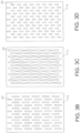
- Non-limiting examples of such additional patterns are shown in Figures 3B-3D . As described hereinbelow, these spaces or areas between adhesive allow for expansion of the adhesive.
- the WBHEA pattern may be configured in various ways to fit the final product and provide the desired padding.
- the pattern may be a series of linear or non-linear spaced apart deposits of adhesive. These deposits may be connected at one or more places or may be positioned in a parallel or non-parallel configuration.
- Figure 3 shows a linear pattern of adhesive deposits.
- the pattern may outline various geometric shapes such as squares, rectangles, triangles, spirals, lines or beads, circles and the like. Alternatively, the pattern may be contiguous in one direction.
- a production line 100 is shown schematically.
- Line 100 includes several forming and processing stations which are used to form the wrap and the envelope. These stations describe and show the preferred processing steps in accordance with the present invention. However, it may be appreciated that not all the steps need be practiced to form the wrap or the envelope, and the steps which are provided need not be necessarily used in the order described hereinbelow.
- station 110 depicts a substrate supply station (splicer and/or unwinding station) which is designed to supply a substrate 115 which is formed into the envelope 10.
- the substrate 115 may be supplied from a number of rolls 110a, 110b placed in a splicer.
- a splicer As is well known, when the line is running, one or more of the rolls is unwinding to supply the substrate while other of the rolls are maintained in reserve (static). The unwinding roll is held back through means of a large roller break thus creating tension on the substrate as it is fed into the production line.
- the splicer will splice a second roll so that the line may be run continuously without slow down or shut down.
- paper is used as the substrate.
- a wide variety of materials may be used to form the web and envelope.
- the substrate 115 is fed to station 120 which is an infeed station.
- the infeed station takes the substrate 115 from the supply station and feeds it into the production line at a controlled repeatable rate.
- This infeed station 120 includes several non-drive rollers and one or more drive rollers. It is contemplated that smaller envelopes may be run with one web while larger envelopes may be run with 2 or more webs.
- the drive roller receives rotational drive via connection to a common line shaft that runs from the infeed to a rotary cutter which will be described in detail hereinbelow. Alternately, servo motors can be directly connected to the drive rollers independently.
- the substrate is fed to station 130 which is an imaging station.
- the imaging station 130 utilizes any appropriate printing method, such as a flexographic print station, to deliver a printed image onto the substrate 115 as the substrate is moving through the imaging station.
- Information such as a bar code, company logo, advertisement or other information can be printed on the substrate at the imaging station.
- Pre-printed roll stock may also be used instead of printing in the production line.
- the printed substrate is next fed into an infrared (IR) dryer station 135.
- IR infrared
- This station employs an IR lamp to dry the ink.
- the printed substrate is next fed to station 140 which is a combination ribbon deck and web slitting station.
- the station slits the substrate into smaller ribbons, which may be a variety of different widths, typically 4 individual ribbons 111a - 111d. These ribbons 111a - 111d make up the layers 11a - 11d of envelope 10 as shown in Figures 1-3 .
- vent perforations if desired are placed in the surface of ribbons 2 and 3 (111b and c) These vent perforations 40 are shown in Fig. 3A .
- the four ribbons (111a - 111d) then engage the ribbon deck of station 140.
- the ribbon deck station 140 arranges the 4 ribbons in vertical sequence over one another.
- the ribbons are numbered 1-4 (111a - 111d) from bottom to top as shown in Fig. 4 .
- Optional web guides 155 provide side-to-side alignment of the ribbons and facilitate guidance from the ribbon deck station 150 to the next station which is the first gluer station.
- a gluer station 159 includes two gluers, one lower and one upper.
- a first lower gluer 160 which is used to apply a pattern of glue onto the ribbon number 1.
- Glue is placed on the top surface of ribbon number 1 from a transfer roller which takes up glue from a pan reservoir and delivers the glue to the top of ribbon 1 or via any appropriate application method in a glue line pattern which is described hereinabove as glue line 13 with respect to Figures 1-3 .
- the desired glue pattern may be formed by various methods, including placing indicia on the cylinder to form the desired pattern. For example, sticky pads may be placed on the cylinder to form the desired glue pattern.
- Gluer station 159 includes a second upper gluer 180 which lays down a pattern of glue on the top side of ribbon 3. Glue is placed on the top surface of ribbon number 3 from a transfer roller which takes up glue from a pan reservoir and delivers the glue to the top of ribbon 3 or via any appropriate application method in a glue line pattern which is described hereinabove as glue line 13 with respect to Figures 1-3 .
- the desired glue pattern may be formed by various methods, including placing indicia on the cylinder to form the desired pattern. For example, sticky pads may be placed on the cylinder to form the desired glue pattern.
- a first lower extruder 170 accommodates ribbon 1.
- the expandable adhesive is extruded in a designated ribbon pattern as described above and deposited on ribbon 1 inside the glue line pattern applied by glue station 160.
- the pattern of deposition of the expandable adhesive is described above as expandable adhesive 30 in Figures 2-3 .
- the expandable adhesive may be applied by contact or non-contact extrusion valves, rotary screen printing, slot die extrusion, flexographic printing or other techniques.
- Extruder station 169 also includes in stacked arrangement, a second upper extruder 200 which extrudes expandable adhesive in a designated pattern onto the upper surface of ribbon 3 within the previously glued area as described above. This is shown schematically in Figure 7 .
- the glue line 13 and the pattern of expandable adhesive 30 on ribbon 1 (sheet 11a) is shown schematically in Figure 5 .
- Station 169 optionally also includes a vision system 175 which provides quality control (QC) monitoring of the pattern of glue deposited on the ribbons.
- QC quality control
- a lower and upper transport station 185 helps drive the ribbons to the next station.
- ribbon 1 is married to ribbon 2.
- ribbon 3 is married to ribbon 4.
- rollers may be applied to provide tension to the ribbons, if necessary.
- the lower two ribbons (1 & 2) are then fed to station 190 which is a third gluer station.
- glue is applied to the upper surface of ribbon 2 in a pattern described above with respect to glue line 13 as shown in Figures 2 and 3 .
- Figures 6 and 7 show schematically the attachment of ribbon 1 to ribbon 2 and the separate attachment of ribbon 3 to ribbon 4. This is shown for clarity.
- the expandable adhesive 30 should be only minimally compressed, i.e., not substantially compressed between the ribbons at this stage.
- the ribbons are then fed into the next station which is a finishing station 199.
- This station finishes the glued four ribbon web into a mailer.
- This process includes optionally (a) a scoring unit for ease of entry flap, (b) a transfer merge unit in which ribbons 1 and 2 are merged with ribbons 3 and 4.
- a thin adhesive line 21 is laid down on layer 11d. The side edge 23 of layer 11a is folded onto adhesive line 21 to close the envelope.
- the ribbons then enter a rotor/cutter station 220.
- two variable speed driven rollers gather the four married ribbons and feed these into the cutter.
- the speed of the rollers may be variable.
- the operator can create additional tension on the ribbons as they are fed through the line by adjusting the speed of the rollers.
- the envelopes 10 are then cut into the final length.
- the individual envelopes exit the rotary cutter onto a delivery table.
- the envelope 10 with pocket 19 is shown in Figure 9 .
- a delivery conveyor 230 transfers the cut envelopes to heating/drying station 240.
- RF energy is used to effect the heating and drying.
- the expandable adhesive between ribbons 1 and 2 and ribbons 3 and 4 expand to form the padded envelope described above.
- the by-product of expansion of the expandable adhesive 30 steam is released between ribbons 1 and 2 and ribbons 3 and 4 through the spaces 14 in glue line 13.
- vents for releasing water evaporation may be formed through punctures or perforations in the paper ribbons, i.e., web substrates.
- One skilled in the art can adjust the number of perforations, punctures, and/or configuration of the seam adhesive perimeter based on the porosity and thickness of the substrates.
- one of the layers 11 of envelope 10 which are laminated together may include a pattern of perforations 40.
- This pattern of perforation serves the same purpose as the spaces 14 shown in Figure 3 .
- the perforations 40 may be used in addition to or in place of space 14.
- Layers 11a-11d are shown both prior to RF expansion in Figure 9 and after RF expansion in Figure 10 .
- a sizing and shaping station 260 is provided just beyond station 240 . For clarity, this is shown in top view in Fig. 4 .
- This function which may be achieved by pressure, provides uniform sizing and shaping for the expandable adhesive resulting in a uniform thickness of envelope 10.
- Line 100 includes several forming and processing stations which are used to form the wrap and the envelope. These stations describe and show processing steps in accordance with the present invention. However, it may be appreciated that not all of the steps need be practiced to form the wrap or the envelope, and the steps which are provided need not be necessarily used in the order described hereinbelow.
- station 110' depicts a substrate supply station which is designed to supply a substrate 115' which is formed into the envelope.
- the substrate 115' is supplied from two rolls 110a', 110b' placed in a splicer.
- a splicer As is well known, when the line is running, one roll is unwinding to supply the substrate while the other roll is maintained in reserve. The unwinding roll is held back through means of a large roller break thus creating tension on the substrate as it is fed into the production line.
- the splicer will splice the second roll so that the line may be run continuously without slow down or shut down.
- paper is used as the substrate.
- a wide variety of materials may be used to form the web and envelope.
- the substrate 115' is fed to station 120' which is an infeed station.
- the infeed station takes the substrate 115' from the supply station and feeds it into the production line at a controlled repeatable rate.
- This infeed station 120' includes several non-drive rollers and one drive roller.
- the drive roller receives rotational drive via connection to a common line shaft that runs from the infeed to a rotary cutter which will be described in detail hereinbelow.
- the substrate is fed to station 130' which is an imaging station.
- the imaging station 130' utilizes digital print heads that will electrically deliver a printed image onto the substrate 115' as the substrate is moving through the imaging station.
- Information such as a bar code, company logo, advertisement or other information can be printed on the substrate at the imaging station.
- the printed substrate is next fed to station 140' which is a web slitting station.
- the web slitting station slits the substrate which is typically 40 inches in width into smaller ribbons, typically 4 individual ribbons 115a' - 115d'.
- These ribbons 111a' - 111d' make up the layers 11a - 11d of the envelope.
- the four ribbons (111a' - 111d') are then transferred to station 150' which is a ribbon deck.
- the ribbon deck station 150' which employs a dry roller, arranges the 4 ribbons in vertical sequence over one another.
- the ribbons are numbered 1-4 (111a - 111d) from bottom to top as shown in Fig. 4A .
- Optional web guides 155' help take the ribbons from the ribbon deck station 150' to the next station which is first gluer station 160'.
- First gluer station 160' is used to apply a pattern of glue onto ribbon number 1 while allowing ribbons 2-4 to pass therethrough.
- Glue is placed on the top surface of ribbon number 1 from a transfer roller which takes up glue from a pan reservoir and delivers the glue to the top of ribbon 1 in a glue line pattern.
- Sticky back pads placed on the cylinder form the desired glue pattern.
- the ribbons are passed to a first extruder station 170'.
- Station 170' accommodates ribbon 1 while allowing ribbons 2-4 to pass therethrough.
- the expandable adhesive is extruded in a designated ribbon pattern as described above and deposited on ribbon 1 inside the glue line pattern applied by glue station 160'.
- the pattern of deposition of the expandable adhesive may be as described above.
- the expandable adhesive may be applied by contact or non-contact extrusion valves, rotary screen printing, slot die extrusion, flexographic printing or other techniques.
- the glue line and the pattern of expandable adhesive on ribbon 1 (sheet 11a) after it exits first extruder station 170' is generally as shown and described above.
- Second gluer station 180' lays down a pattern of glue on the top side of ribbon 2.
- the pattern may be U-shaped so as to allow the final product to function as a padded envelope.
- the U-shaped glue pattern provides an opening for the envelope. This is deposited as a glue line with an open side.
- ribbon 2 is also married over the top of ribbon 1 forming a lower half of the padded envelope.
- Ribbon 1 (sheet 11a) is married to ribbon 2 (sheet 11b). As sheet 11b is placed over sheet 11a it flattens and spreads the expandable adhesive.
- rollers may be applied to provide tension to the ribbons, if necessary.
- the ribbons are then fed to station 190' which is a third gluer station.
- glue is applied to the upper surface of ribbon 3.
- the next station 200' is a second extruder station which extrudes expandable adhesive in a designated pattern onto the upper surface of ribbon 3 within the previously glued area as described above.
- Fig. 4A attaches ribbon 1 to ribbon 2, then attaches ribbon 3 to ribbons 1/2, and then attaches ribbon 4 to ribbons 1/2/3.
- the expandable adhesive should be only minimally compressed, i.e., not substantially compressed between the ribbons at this stage.
- the ribbons are then fed into the next station which is a tape applicator station 210'. All fours ribbons become married as they enter station 210'.
- a double sided tape along with a protective release strip, is applied. The tape is applied to the portion of the ribbon which forms the envelope. The tape and the release strip will be fed onto the running envelope in a continual stream just prior to rotary cutting.
- the ribbons then enter a rotary cutter station 220'.
- two variable speed driven rollers gather the four married ribbons and feed these into the cutter.
- the speed of the two rollers is variable.
- the operator can create additional tension on the ribbons as they are fed through the line by adjusting the speed of the rollers.
- the envelopes are then cut into the final length.
- the individual envelopes exit the rotary cutter onto a delivery table.
- a delivery conveyor 230' transfers the cut envelopes to heating/drying station 240'.
- RF energy is used to effect the heating and drying.
- the expandable adhesive between ribbons 1 and 2 and ribbons 3 and 4 expand to form the padded envelope described above.
- the by-product of expansion of the expandable adhesive steam is released between ribbons 1 and 2 and ribbons 3 and 4 through the spaces (vents) 14 in the glue line.
Landscapes
- Engineering & Computer Science (AREA)
- Mechanical Engineering (AREA)
- Physics & Mathematics (AREA)
- Plasma & Fusion (AREA)
- Thermal Sciences (AREA)
- Making Paper Articles (AREA)
- Laminated Bodies (AREA)
- Buffer Packaging (AREA)
- Adhesives Or Adhesive Processes (AREA)
Description
- The present invention relates to a method of manufacturing a protective padded wrap as well as to a padded open-ended pouch
- In order to protect various items during handling, shipping or transportation, protective products such as padded wraps, envelopes, packages and containers are currently used. Such protective products may be placed in surrounding engagement with the product to protect the product from potentially damaging contact. In addition, such padded wraps may be used to form a protective pouch or an envelope which permits the product to be shipped in a protective manner. Such protective products traditionally used closed cell extruded polystyrene foam to form a cushion or plastic "bubble wrap" material which relies on an air gap or bubble between the plastic layers, to form the protective cushion. However, as may be appreciated, plastic bubble wrap packages and polystyrene foam are not an environmentally sound way of protecting various items. Attempts to make more environmentally friendly protective wrap have drawbacks including high shipping weight, non-uniformity in the protective layer and lack of the requisite consistent protective quality. For example, alternative approaches have focused on eco-friendly, biodegradable and/or compostable products, such as cellulose-based substrates, sourced from renewable materials. However, as the package is handled and flexed, the air gaps between the two substrates become compressed and the protective cushion area is decreased in those compressed areas. Conventional cellulosic alternatives still suffer from high shipping weight (excessive padding material) and inconsistent protective padded areas.
- More recently, adhesive compositions having thermally insulative and cushion-like properties have been provided for use in protective packages and wrap. For example, see
US 9,580,629 US 8,747,603 ,US 9,273,230 US 9,657,200 US 20140087109 ,US 20170130399 ,US 20170130058 , andUS 20160263876 . These packages are formed with an air gap in the coating/adhesive sandwiched between two substrates, which provides insulation. These prior adhesives required conventional oven heating for curing/coalescing the adhesive (polymers), which means prolonged process time and large manufacturing space to allow for water evaporation. Moreover, as the size of the packages vary, the insulative gap is not always uniform. While microwave heating provides strict controls for level of moisture and uniform air gaps, the depth of penetration using microwave heating is limited only to about 3.81 cm (1.5 inches). Thus, any substrate that has a thickness greater than about 3.81 cm (1.5 inches ) may result in nonuniform packages. -
US 4,087,002 relates to a cushioned shipping bag having first and second exterior faces formed by outer surfaces of at least one exterior layer of relatively thin, fibrous, and flexible sheet material, an inner layer lining substantially the entire bag interior and comprising at least one sheet of foamed plastic, said foam being prestretched relative to said fibrous sheet material and thereby contributing bag-opening curvature to the bag faces, the bag having at least one edge seam wherein two thicknesses of said foamed plastic have been collapsed under heat and pressure to provide marginal areas of said exterior thin, fibrous, and flexible sheet bonded substantially surface-to-surface, the marginal area being greatly reduced in thickness by collapse of the foam thereat, and said bag having a joined and integral continuum of said foamed plastic traversing the interior of said marginal area, said foam being fused together and still at least partly expanded by a lesser application of heat and pressure inward of the marginal area, said continuum of foam traversing the interior of said marginal area providing an improved seal and cushioning across the seam. -
US 2014/0141185 discloses a hot melt assist waterborne adhesive composition comprising: a) an emulsion polymer that has a Tg value of from about -50° C. to about 80° C, b) a preservative, c) a plurality of pre-expanded microspheres; and d) water, wherein the microspheres have a volume fraction ranging from about 10 to 40 V/V % based on the total volume of the adhesive. The disclosed adhesive is claimed to be suitable as a partial or complete replacement to hot melt adhesives for use in converting paper and packaging process. -
US 2013/303351 relates to a method for manufacturing, comprising: positioning blanks on a conveyor system; applying heat-expandable particles in a pattern on the blanks as a belt of the vacuum conveyor system moves the blanks below an applicator; heating the particles with a microwave heater to expand the particles; and sending the blanks along the conveyor system to a product-building machine that assembles products from the blanks.
WO 2016/014486 is concerned with a coating composition comprising:
(a) a water-based polymer prepared by emulsion polymerization; (b) a plurality of expandable microspheres having a To (onset of expansion) and Tm (maximum expansion); and (c) optionally, an additive, wherein the polymer has a modulus less than 0.3MPa and a tanδ is greater than 0.35 at (Tm-T0)/2. - There is a need in the art for methods to provide uniform protective padding for all sizes of packages. The present invention provides methods to produce environmentally and economically sound package padding (cushioning), as well as insulation material, such that uniform protective products such as wraps and pouches can be made.
- The present invention solves the problems associated with prior art protective and insulated products, while also being eco-friendly.
- The protective wraps manufactured by the method of the present invention have greater structural integrity than similar currently available kraft paper and plastic bubble products, while providing a fully recyclable paper option that reduces the environmental impact of shipping and e-commerce. This is due in part to the combination of materials used and the process of manufacturing employed. The present invention also uses less paper than other eco-friendly mailers, which are heavy and have higher shipping costs.
- As used herein, the terms web substrates, layers and ribbons will be used interchangeably.
- In one aspect of the invention there is provided a method of manufacturing a protective padded wrap on a continuous manufacturing line, as defined in
claim 1 - The thus formed protective padded wrap may be further joined with a second protective wrap by sealing their respective perimeters to form an open pouch therebetween, which may include and open end and an associated closure flap. In other words, the above steps may be used to create a final multi-layered sheet-like product which may be rolled up and/or cut to size, as well as an intermediate product which can then be further processed to make a different final product, such as a mailer or other product structure, by mating individually formed padded wraps to form a pouch therebetween. As will be also discussed herein, additional manufacturing methods for making mailers and protective products are also disclosed.
- Padded wraps made in accordance with the teachings described herein, may be rolled up onto spools for storage or distribution similar to rolls of bubble wrap, or may be cut into smaller padded wrap sections and formed into individual padded units, such as mailers or envelope products.
- In still another aspect of the invention there is provided a padded open ended pouch as defined in claim 6
-
-
Figure 1 is a plan view showing of a protective envelope formed in accordance with the present disclosure, however not within the scope of the present invention as claimed. -
Figure 2 is schematic representation of the layers used to form the envelope ofFigure 1 . -
Figure 3 is a plan view of one layer of the envelope shown inFigure 2 including an expandable adhesive pattern. -
Figure 3A is a plan view of one layer of the envelope showing multiple perforations. -
Figure 3B-3D show alternate arrangements of the pattern of expandable adhesive. -
Figure 4 is a schematic representation of a preferred in-line process used to form the envelope ofFigure 1 . -
Figure 4A is a schematic representation of an alternate in-line process used to form an envelope of the present disclosure. -
Figures 5-10 show schematically successive representations of the layers through the in-line process ofFigure 4 for forming the envelope ofFigure 1 . - The present invention provides an improved padded wrap by employing expandable adhesive between layers of the envelope. As will be described in further detail hereinbelow, an expandable adhesive is positioned between layers of a multi-layer envelope. When the expandable adhesive is subjected to heat such as may be provided by RF energy, the expandable adhesive expands to provide padding between the layers.
- While an envelope is disclosed having two multi-layered webs forming a pocket for receiving a product to be protected, it may be appreciated that a padded wrap may also be formed by employing one of the multi-layered padded webs.
- The water-based heat-expandable adhesives (WBHEAs) of the present invention may be selected from a variety of compositions. Useful compositions for the WBHEAs are described in
US Application 62/533,957, filed 18 July 2017 - The water-based polymer may be present in the composition in any amount, and desirably is present in an amount of from about 60% to about 99.5 wt%, preferably from about 65% to about 95 wt%, by weight of the composition prior to setting of the composition.
- The WBHEAs of the present invention desirably have a solids content of about 40% to about 70% by weight of the total adhesive composition, and more desirably about 50% to about 60% by weight of the total adhesive composition.
- The WBHEAs of the present invention desirably have a viscosity which permits high speed application on a moving web substrate to allow continuous manufacturing. Thus the rheology of the adhesive must have sufficient structural body to be deposited and remain in place during processing. For example, the viscosity must be high enough not to appreciably migrate when deposited on the substrate and to remain substantially stationary through the manufacturing process, such that when expanded, a substantially uniform padded product results. Useful ranges of viscosities include 500 to about 5,000 mPas (500 to about 5,000 cPs) at about 25°C to about 40° C, and desirably about 1,500 mPas (1,500 cPs) to about 5,000 mPas (5,000 cPs) at about 25°C to about 40° C.
- The WBHEAs of the present invention include a plurality of heat-expandable microspheres having an initial expansion temperature range of from about 35° C to about 110° C and a maximum expandable temperature range of about 50° C to about 150° C. These microspheres may be made from a variety of materials, but generally have a polymeric shell and a hydrocarbon core. A blowing agent generally comprises the core and it is designed to activate upon reaching a specified temperature.
- One particularly useful heat-expandable microsphere comprises a polyacrylonitrile shell and a hydrocarbon core, such as those sold under the trade names DUALITE® AND EXPANCEL®. The expandable microspheres may have any expanded size, including from about 5 microns to about 30 microns in diameter. In the presence of heat, the microspheres may increase from about 3 to about 10 times their diameter.
- The expandable microspheres have a particular temperature at which they begin to expand and a second temperature at which they have reached maximum expansion. Microsphere grades are typically sold with specific expansion (Texp) temperatures and maximum expansion temperatures (Tmax). The initial expansion temperature (Texp) is the typical temperature at which the microspheres start to expand (Texp), and the maximum expansion temperature (Tmax) is the temperature at which the about 80% of the microspheres have expanded. If the microspheres are exposed to temperature far greater than Tmax, the microspheres start to explode and deflate.
- Depending on the fully expanded size of the microspheres, the amount of the expandable microspheres in the composition can be adjusted. Depending upon the particular expandable microspheres used in the composition, the desired amount of the microspheres in the composition may be modified.
- The microspheres further increase the structural integrity of the coalesced composition after they are expanded. While introducing voids in a matrix typically decreases mechanical integrity, the microspheres in the polymeric matrix provide stiffness when applied onto substrates. This is particularly useful for packaging fragile contents.
- The microsphere may be pre-expanded. If pre-expanded microspheres are added in the composition, the pre-expanded microspheres should be chosen so the RF heating will not start to decompose the microspheres. Yet in another embodiment, the microspheres may be a mixture of pre-expanded and expandable microspheres.
- The present invention provides dielectric heating, particularly RF heating, a foamable waterborne composition. RF creates an alternating electric field between a dielectric material, in this invention, polar water molecules. The expandable adhesive is conveyed between the electrodes causing the water molecules in the composition to continuously reorient to face opposite electrodes. Friction from this molecular movement causes the rapid heating. RF operates at much lower frequency than microwave heating, and is associated with lower health risks than microwaves. RF is also suitable for heating bulkier and odd-shaped containers due to its higher depth of penetration.
- The RF heating concurrently drives the water away from the composition to coalesce the water-based polymer and expands the microspheres as the temperature reaches the activation state of the microspheres. Heating at RF frequencies of about 14, 27 and 41 MHz, are particularly preferred. The RF devices can be designed with operational amplifiers for optimal heating.
- The composition optionally further includes any plasticizers, tackifiers, humectants, accelerators, fillers, pigments, dyes, stabilizers, rheology modifiers, polyvinyl alcohols, preservatives, e.g., antioxidant, biocide; and mixtures thereof. These components can be included in an amount of from about 0.05% to about 15% by weight of the expandable adhesive composition.
- Exemplary plasticizers are dibenzoates available as BENZOFLEX®, such as diethylene glycol dibenzoate, dipropylene glycol dibenzoate, and the like.
- Exemplary preservatives include 1,2-benzisothiazolin-3-one, 5-chloro-2-methyl-4-isothiazolin-3-one and 2-Methyl-4-isothiazolin-3-one. Typically, preservatives may be used in an amount of from about 0.05% to about 0.5% by weight of the WBHEA composition prior to setting of the composition.
- Exemplary fillers include pearl starch, physically modified starch, and chemically modified starch.
- Other materials that do not adversely affect the WBHEA composition and the protective or insulating properties of the composition may be used as desired. Other additives, such as accelerators may be included in the WBHEA composition to increase the coalescence of the composition, if desired. For example various salts may be added to increase throughput and help decrease set time of the formulation. Examples of such salts include multivalent cations from water soluble salts, such as aluminum nitrate, zirconium acetate and ammonium zirconyl carbonate (available as Bacote 20 from Zirconium Chemicals). Such accelerants may generally be added in amounts of about 0.05% to about 1.0% by weight based on the total weight of the WBHEA composition.
- Although the WBHEA composition can start to coalesce at room temperature, the high moisture content and will be substantially fluid until the moisture content is about 20, 19, 18, 17, 16, 15, 14, 13, 12, 11, 10, 9, 8, 7, 6, 5, 4, 3, 2 or 1 wt%, based on the total weight. Preferably, the moisture content should be maintained at levels greater than about 20 wt% to prevent premature coalescence. Premature coalescence can lead to uneven drying, leading to uneven thickness of the dried composition on substrates.
- RF heating also allows for fast throughput of making articles. The composition must be designed to accommodate this fast throughput method to maximize solid contents in the composition. It is preferable that the water molecules to be efficiently driven off without leaving unsightly wrinkles or unevenness on the substrates.
- One particularly useful WBHEA composition includes:
Table Component %Wt. of Total Composition Range Resin Emulsion* 85.4% 70-95% Expandable Microspheres 8.0% 4-25% Benzoflex K88, Eastman 4.0% 0-10% Glycerin 2.4% 0-4% Methocel, K4M, Colorcon 0.1% 0-1% Kathon, Dow Chemical 0.1% 0-1% NaCl ---- 0-5% *polyvinyl acetate aqueous emulsion, solids content 54-58%; available under Dur-O-Set C325, Celanese. - The envelope of the present disclosure may now be described with respect to the Figures.
- An
envelope 10 in accordance with the present disclosure is shown inFigure 1 .Envelope 10 can take any conventional size (i.e., length and width) and shape and generally optionally includes an opening closable by aflap 10a (also shown inFigures 5-10 ). As will be described in further detail hereinbelow, theflap 10a includes a double-sided tape strip 10b covered by arelease layer 10c. When therelease liner 10c is removed and theflap 10a folded onto the envelope the double-sided tape closes the opening. Foldline 10d is shown inFigure 1 . While double-sided tape is shown in the preferred embodiment, it may be appreciated that any appropriate closure may be employed. - Referring additionally to
Figure 2 , theenvelope 10 of the present disclosure includes four layers 11 denoted aslayers 11a - 11d as shown from top to bottom inFigure 2 . In the present illustrative embodiment, each layer, which is also referred to as a web substrate or ribbon, is typically formed of paper. While paper is shown as a preferred embodiment, it may be appreciated that other materials may be used to form the substrate of layers 11. For example, wax-coated paper, paper with plastic, or water-resistant or stain-resistant coatings are useful. Pre-printed rolls of paper or other material may also be used to provide advertising or other information on the final product. -
Layer 11a which is the bottom layer, is further shown in detail inFigure 3 , and includes the extendingflap 10a ofFigure 1 , the double-sided tape strip 10b andrelease layer 10c. In all other respects,layer 11a is substantially similar tolayer 11c.Layers Figure 2 )are paper substrates where, as will be described in further detail hereinbelow,layer 11b is attached tolayer 11a andlayer 11d is attached to layer 11c. - The substrate layers may be made from a variety of eco-friendly materials. Desirably the substrates are made from cellulosic materials such as paper. Referring now to
Figures 2 and3 ,layer 11a is provided on the upper surface with aglue line 13 perimetrically about thesheet 11a. Theglue line 13, which is applied in a manner described hereinbelow, is generally contiguous about the perimeter oflayer 11a but hasperiodic spaces 14 therebetween.Layer 11b is applied tolayer 11a such that the adhesive will bind the perimeters oflayer 11a to layer 11b. It is noted that theglue line 13 on the perimeter of 11a is interrupted by theperiodic spaces 14 therebetween such that where whenlayer 11b is applied tolayer 11a no sealing will take place atspace 14. This provides air gaps between the layers for purposes which will be describe hereinbelow. The precise location and size of the spaces or air gaps may be varied. - Alternately or in addition, a pattern of
vent perforations 40 may be placed in theenvelope 10 for similar purposes, as also described and set forth hereinbelow and shown inFigure 3A , thevent perforations 40 may also be used for venting steam. -
Layer 11c (Figure 2 )includessimilar glue line 13 around the perimeter of the upper surface withspaces 14 therebetween and accommodateslayer 11d thereon in a similar sealed fashion. -
Layer 11b includes on its upper surface aglue line 15 which extends on upper and lower sides of theupper surface layer 11b. Theglue line 15 may be continuous on all three sides. Theglue line 15 allowslayer 11b to be sealed tolayer 11c. Oneunglued edge 15a forms an open end which defines the opening of the pocket in the envelope when the four layers are laminated together. - With respect to
layers Figure 2 ), disposed within the perimeter on the upper surface of the layers is a pattern ofexpandable adhesive 30. Expandable adhesive (WBHEA) 30 is applied in a pattern where spaces exist between multiple adhesive deposits. The pattern is chosen to allow for appropriate expansion of the adhesive. The absence of space to allow proper expansion is thus not desirable nor generally optimum. Any chosen pattern may include one or more variations of spacings for expansion. For example, discrete areas of adhesive may be used, which are unconnected or discontinuous to other discrete areas of adhesive; or discrete areas of adhesive may be used in combination with connecting bridges of adhesive between the discrete areas, such that they are connected but still provide expansion room. The discrete areas of adhesive may be any shape or configuration to serve the purpose of providing a protective padding upon expansion. Non-limiting examples of such additional patterns are shown inFigures 3B-3D . As described hereinbelow, these spaces or areas between adhesive allow for expansion of the adhesive. The WBHEA pattern may be configured in various ways to fit the final product and provide the desired padding. For example, the pattern may be a series of linear or non-linear spaced apart deposits of adhesive. These deposits may be connected at one or more places or may be positioned in a parallel or non-parallel configuration.Figure 3 shows a linear pattern of adhesive deposits. The pattern may outline various geometric shapes such as squares, rectangles, triangles, spirals, lines or beads, circles and the like. Alternatively, the pattern may be contiguous in one direction. - A method of manufacturing the protective padded wrap and an envelope formed therefrom may now be described with reference to
Fig. 4 . - A
production line 100 is shown schematically.Line 100 includes several forming and processing stations which are used to form the wrap and the envelope. These stations describe and show the preferred processing steps in accordance with the present invention. However, it may be appreciated that not all the steps need be practiced to form the wrap or the envelope, and the steps which are provided need not be necessarily used in the order described hereinbelow. - Referring again to
Fig. 4 ,station 110 depicts a substrate supply station (splicer and/or unwinding station) which is designed to supply asubstrate 115 which is formed into theenvelope 10. Thesubstrate 115 may be supplied from a number ofrolls 110a, 110b placed in a splicer. As is well known, when the line is running, one or more of the rolls is unwinding to supply the substrate while other of the rolls are maintained in reserve (static). The unwinding roll is held back through means of a large roller break thus creating tension on the substrate as it is fed into the production line. When a first roll runs out, the splicer will splice a second roll so that the line may be run continuously without slow down or shut down. In the present illustrative embodiment, paper is used as the substrate. However, a wide variety of materials may be used to form the web and envelope. - The
substrate 115 is fed to station 120 which is an infeed station. The infeed station takes thesubstrate 115 from the supply station and feeds it into the production line at a controlled repeatable rate. Thisinfeed station 120 includes several non-drive rollers and one or more drive rollers. It is contemplated that smaller envelopes may be run with one web while larger envelopes may be run with 2 or more webs. The drive roller receives rotational drive via connection to a common line shaft that runs from the infeed to a rotary cutter which will be described in detail hereinbelow. Alternately, servo motors can be directly connected to the drive rollers independently. - Next, the substrate is fed to station 130 which is an imaging station. The
imaging station 130 utilizes any appropriate printing method, such as a flexographic print station, to deliver a printed image onto thesubstrate 115 as the substrate is moving through the imaging station. Information such as a bar code, company logo, advertisement or other information can be printed on the substrate at the imaging station. Pre-printed roll stock may also be used instead of printing in the production line. - The printed substrate is next fed into an infrared (IR) dryer station 135. This station employs an IR lamp to dry the ink.
- The printed substrate is next fed to station 140 which is a combination ribbon deck and web slitting station. The station slits the substrate into smaller ribbons, which may be a variety of different widths, typically 4
individual ribbons 111a - 111d. Theseribbons 111a - 111d make up thelayers 11a - 11d ofenvelope 10 as shown inFigures 1-3 . Also atstation 140 vent perforations if desired are placed in the surface ofribbons 2 and 3 (111b and c) Thesevent perforations 40 are shown inFig. 3A . - In addition, the four ribbons (111a - 111d) then engage the ribbon deck of
station 140. Theribbon deck station 140 arranges the 4 ribbons in vertical sequence over one another. For present purposes, the ribbons are numbered 1-4 (111a - 111d) from bottom to top as shown inFig. 4 . - Optional web guides 155 provide side-to-side alignment of the ribbons and facilitate guidance from the
ribbon deck station 150 to the next station which is the first gluer station. - A gluer station 159 includes two gluers, one lower and one upper. A first
lower gluer 160 which is used to apply a pattern of glue onto theribbon number 1. Glue is placed on the top surface ofribbon number 1 from a transfer roller which takes up glue from a pan reservoir and delivers the glue to the top ofribbon 1 or via any appropriate application method in a glue line pattern which is described hereinabove asglue line 13 with respect toFigures 1-3 . The desired glue pattern may be formed by various methods, including placing indicia on the cylinder to form the desired pattern. For example, sticky pads may be placed on the cylinder to form the desired glue pattern. - Gluer station 159 includes a second
upper gluer 180 which lays down a pattern of glue on the top side ofribbon 3. Glue is placed on the top surface ofribbon number 3 from a transfer roller which takes up glue from a pan reservoir and delivers the glue to the top ofribbon 3 or via any appropriate application method in a glue line pattern which is described hereinabove asglue line 13 with respect toFigures 1-3 . The desired glue pattern may be formed by various methods, including placing indicia on the cylinder to form the desired pattern. For example, sticky pads may be placed on the cylinder to form the desired glue pattern. - Next, the ribbons are passed to an
extruder station 169. A firstlower extruder 170 accommodatesribbon 1. At theextruder 170, the expandable adhesive is extruded in a designated ribbon pattern as described above and deposited onribbon 1 inside the glue line pattern applied byglue station 160. The pattern of deposition of the expandable adhesive is described above as expandable adhesive 30 inFigures 2-3 . The expandable adhesive may be applied by contact or non-contact extrusion valves, rotary screen printing, slot die extrusion, flexographic printing or other techniques. -
Extruder station 169 also includes in stacked arrangement, a secondupper extruder 200 which extrudes expandable adhesive in a designated pattern onto the upper surface ofribbon 3 within the previously glued area as described above. This is shown schematically inFigure 7 . - The
glue line 13 and the pattern of expandable adhesive 30 on ribbon 1 (sheet 11a) is shown schematically inFigure 5 . -
Station 169 optionally also includes avision system 175 which provides quality control (QC) monitoring of the pattern of glue deposited on the ribbons. - A lower and upper transport station 185 helps drive the ribbons to the next station. In the
lower transport station 187,ribbon 1 is married toribbon 2. In theupper transport station 186,ribbon 3 is married toribbon 4. - At this stage, optional rollers may be applied to provide tension to the ribbons, if necessary.
- The lower two ribbons (1 & 2)are then fed to station 190 which is a third gluer station. At the
third gluer station 190, glue is applied to the upper surface ofribbon 2 in a pattern described above with respect toglue line 13 as shown inFigures 2 and3 . -
Figures 6 and 7 show schematically the attachment ofribbon 1 toribbon 2 and the separate attachment ofribbon 3 toribbon 4. This is shown for clarity. In addition, while schematically shown, theexpandable adhesive 30 should be only minimally compressed, i.e., not substantially compressed between the ribbons at this stage. - The ribbons are then fed into the next station which is a finishing
station 199. This station finishes the glued four ribbon web into a mailer. This process includes optionally (a) a scoring unit for ease of entry flap, (b) a transfer merge unit in whichribbons ribbons Figure 2 , a thinadhesive line 21, is laid down onlayer 11d. Theside edge 23 oflayer 11a is folded ontoadhesive line 21 to close the envelope. - The ribbons then enter a rotor/
cutter station 220. At the entrance to the cutter, two variable speed driven rollers gather the four married ribbons and feed these into the cutter. The speed of the rollers may be variable. The operator can create additional tension on the ribbons as they are fed through the line by adjusting the speed of the rollers. Theenvelopes 10 are then cut into the final length. The individual envelopes exit the rotary cutter onto a delivery table. Theenvelope 10 withpocket 19 is shown inFigure 9 . - A
delivery conveyor 230 transfers the cut envelopes to heating/drying station 240. - At heating/
drying station 240, in the preferred embodiment, RF energy is used to effect the heating and drying. As the envelopes pass through the dryingstation 240, the expandable adhesive betweenribbons ribbons expandable adhesive 30 steam is released betweenribbons ribbons spaces 14 inglue line 13. Alternatively or in addition to spaces (gaps) in the glue line, vents for releasing water evaporation may be formed through punctures or perforations in the paper ribbons, i.e., web substrates. One skilled in the art can adjust the number of perforations, punctures, and/or configuration of the seam adhesive perimeter based on the porosity and thickness of the substrates. - As shown in
Figure 3A as an example, one of the layers 11 ofenvelope 10 which are laminated together may include a pattern ofperforations 40. This pattern of perforation serves the same purpose as thespaces 14 shown inFigure 3 . Theperforations 40 may be used in addition to or in place ofspace 14. -
Layers 11a-11d are shown both prior to RF expansion inFigure 9 and after RF expansion inFigure 10 . - Additionally, just beyond station 240 a sizing and shaping
station 260 is provided. For clarity, this is shown in top view inFig. 4 . This function, which may be achieved by pressure, provides uniform sizing and shaping for the expandable adhesive resulting in a uniform thickness ofenvelope 10. - While a particular sequence of joining ribbons 1-4 is shown and described herein, as a preferred embodiment," it may be appreciated that the exact path may be varied and other sequences of joining the ribbons may be employed.
- A method of manufacturing the protective padded wrap in accordance with the present invention may now be described with reference to
Fig. 4A . - A production line 100' is shown schematically.
Line 100 includes several forming and processing stations which are used to form the wrap and the envelope. These stations describe and show processing steps in accordance with the present invention. However, it may be appreciated that not all of the steps need be practiced to form the wrap or the envelope, and the steps which are provided need not be necessarily used in the order described hereinbelow. - Referring again to
Fig. 4A , station 110' depicts a substrate supply station which is designed to supply a substrate 115' which is formed into the envelope. The substrate 115' is supplied from tworolls 110a', 110b' placed in a splicer. As is well known, when the line is running, one roll is unwinding to supply the substrate while the other roll is maintained in reserve. The unwinding roll is held back through means of a large roller break thus creating tension on the substrate as it is fed into the production line. When the first roll runs out, the splicer will splice the second roll so that the line may be run continuously without slow down or shut down. In the present illustrative embodiment, paper is used as the substrate. However, a wide variety of materials may be used to form the web and envelope. - The substrate 115' is fed to station 120' which is an infeed station. The infeed station takes the substrate 115' from the supply station and feeds it into the production line at a controlled repeatable rate. This infeed station 120' includes several non-drive rollers and one drive roller. The drive roller receives rotational drive via connection to a common line shaft that runs from the infeed to a rotary cutter which will be described in detail hereinbelow.
- Next, the substrate is fed to station 130' which is an imaging station. The imaging station 130' utilizes digital print heads that will electrically deliver a printed image onto the substrate 115' as the substrate is moving through the imaging station. Information such as a bar code, company logo, advertisement or other information can be printed on the substrate at the imaging station.
- The printed substrate is next fed to station 140' which is a web slitting station. The web slitting station slits the substrate which is typically 40 inches in width into smaller ribbons, typically 4 individual ribbons 115a' - 115d'. These
ribbons 111a' - 111d' make up thelayers 11a - 11d of the envelope. - The four ribbons (111a' - 111d') are then transferred to station 150' which is a ribbon deck. The ribbon deck station 150', which employs a dry roller, arranges the 4 ribbons in vertical sequence over one another. For present purposes, the ribbons are numbered 1-4 (111a - 111d) from bottom to top as shown in
Fig. 4A . Optional web guides 155' help take the ribbons from the ribbon deck station 150' to the next station which is first gluer station 160'. - First gluer station 160' is used to apply a pattern of glue onto
ribbon number 1 while allowing ribbons 2-4 to pass therethrough. Glue is placed on the top surface ofribbon number 1 from a transfer roller which takes up glue from a pan reservoir and delivers the glue to the top ofribbon 1 in a glue line pattern. Sticky back pads placed on the cylinder form the desired glue pattern. - Next, the ribbons are passed to a first extruder station 170'. Station 170' accommodates
ribbon 1 while allowing ribbons 2-4 to pass therethrough. At the extruder station 170', the expandable adhesive is extruded in a designated ribbon pattern as described above and deposited onribbon 1 inside the glue line pattern applied by glue station 160'. The pattern of deposition of the expandable adhesive may be as described above. The expandable adhesive may be applied by contact or non-contact extrusion valves, rotary screen printing, slot die extrusion, flexographic printing or other techniques. - The glue line and the pattern of expandable adhesive on ribbon 1 (
sheet 11a) after it exits first extruder station 170' is generally as shown and described above. - The ribbons are then moved to station 180' which is a second gluer station. Second gluer station 180' lays down a pattern of glue on the top side of
ribbon 2. The pattern may be U-shaped so as to allow the final product to function as a padded envelope. The U-shaped glue pattern provides an opening for the envelope. This is deposited as a glue line with an open side. At this point,ribbon 2 is also married over the top ofribbon 1 forming a lower half of the padded envelope. Ribbon 1 (sheet 11a) is married to ribbon 2 (sheet 11b). Assheet 11b is placed oversheet 11a it flattens and spreads the expandable adhesive. - At this stage, optional rollers may be applied to provide tension to the ribbons, if necessary.
- The ribbons are then fed to station 190' which is a third gluer station. At the third gluer station 190', glue is applied to the upper surface of
ribbon 3. - The next station 200' is a second extruder station which extrudes expandable adhesive in a designated pattern onto the upper surface of
ribbon 3 within the previously glued area as described above. - The method described in
Fig. 4A attachesribbon 1 toribbon 2, then attachesribbon 3 toribbons 1/2, and then attachesribbon 4 toribbons 1/2/3. The expandable adhesive should be only minimally compressed, i.e., not substantially compressed between the ribbons at this stage. - The ribbons are then fed into the next station which is a tape applicator station 210'. All fours ribbons become married as they enter station 210'. At the tape applicator station 210', a double sided tape, along with a protective release strip, is applied. The tape is applied to the portion of the ribbon which forms the envelope. The tape and the release strip will be fed onto the running envelope in a continual stream just prior to rotary cutting.
- The ribbons then enter a rotary cutter station 220'.
- At the entrance to the cutter station 220', two variable speed driven rollers gather the four married ribbons and feed these into the cutter. The speed of the two rollers is variable. The operator can create additional tension on the ribbons as they are fed through the line by adjusting the speed of the rollers. The envelopes are then cut into the final length. The individual envelopes exit the rotary cutter onto a delivery table.
- A delivery conveyor 230' transfers the cut envelopes to heating/drying station 240'.
- At heating/drying station 240', in the preferred embodiment, RF energy is used to effect the heating and drying. As the envelopes pass through the drying station 240', the expandable adhesive between
ribbons ribbons ribbons ribbons
Claims (7)
- A method of manufacturing a protective padded wrap on a continuous manufacturing line, the method including:a.) providing a first continuous web substrate (11a) having a top side and a bottom side, and a length and a width which defines a perimeter and an inner perimeter portion;b.) providing a second continuous web substrate (11b) having a top side and a bottom side, and a length and width which defines a perimeter thereabout and an inner perimeter portion;c.) forming a sealable perimeter portion (13) by applying a layer of sealing adhesive about the perimeter of the top side of the first web to form a sealable perimeter portion, the padded wrap having vents (14) to allow for water evaporation, wherein the vents may be formed from one or more of: gaps in the sealing adhesive; punctures in the inner perimeter portion and perforations in the inner perimeter portion;d.) depositing a pattern of a water-based heat-expandable adhesive (WBHEA) (30) comprising a water-based polymer and a plurality of heat-expandable microspheres on the inner portion of one or more of the first web and the second web (11a, b), the WBHEA (30) forming a protective padded area when expanded;e.) joining the first and second webs (11a, b) at their respective perimeters to form a sealed structure enclosing the WBHEA (30) without substantially compressing the WBHEA (30) therebetween;f.) exposing the sealed structure to RF radiation to expand and set the WBHEA (30) to form the protective padded wrap; andg.) optionally further processing the protective padded wrap to provide a desired uniformity in thickness and/or desired shape in at least one section of the protective padded wrap.
- The method of claim 1, wherein the sealing adhesive is a continuous layer and the sealable perimeter portion includes perforations or punctures for venting.
- The method of claim 1 further comprising:
forming a second protective padded wrap and joining it with the previously formed protective padded wrap by sealing the two protective wraps at their perimeters to form an open pouch therebetween, optionally including a closure flap. - The method of claim 1, wherein the WBHEA pattern is formed by a continuous or discontinuous application of the WBHEA which allows sufficient space for expansion.
- The method of claim 1 wherein the substrate comprises a cellulosic material.
- A padded open-ended pouch comprising:a.) a pair of padded wraps produced according to the method of claim 1 joined substantially about their perimeter by a continuous perimeter adhesive to form an open-ended pouch, each of said padded wraps including:b.) first and second webs of material (11a, b) each having a perimeter and an interior within said perimeter;c.) a perimeter adhesive (13) joining said first and second webs of material at said perimeter; andd.) a pattern of a water-based heat-expanded adhesive (WBHEA) (30) between said first and second webs of material (11a, b) within said perimeter interior for maintaining said first and second webs of material (11a, b) in spaced apart relationship at said interior.
- The padded open-ended pouch of claim 6, wherein the WBHEA pattern is formed by a continuous or discontinuous application the WBHEA which allows sufficient space for expansion.
Priority Applications (1)
| Application Number | Priority Date | Filing Date | Title |
|---|---|---|---|
| EP23195946.1A EP4269258A3 (en) | 2017-08-25 | 2018-08-22 | Process for forming improved protective eco-friendly wrap and packaging made therefrom |
Applications Claiming Priority (2)
| Application Number | Priority Date | Filing Date | Title |
|---|---|---|---|
| US201762550008P | 2017-08-25 | 2017-08-25 | |
| PCT/US2018/047526 WO2019040624A1 (en) | 2017-08-25 | 2018-08-22 | Process for forming improved protective eco-friendly pouch and packaging and products made therefrom |
Related Child Applications (1)
| Application Number | Title | Priority Date | Filing Date |
|---|---|---|---|
| EP23195946.1A Division EP4269258A3 (en) | 2017-08-25 | 2018-08-22 | Process for forming improved protective eco-friendly wrap and packaging made therefrom |
Publications (2)
| Publication Number | Publication Date |
|---|---|
| EP3672805A1 EP3672805A1 (en) | 2020-07-01 |
| EP3672805B1 true EP3672805B1 (en) | 2023-10-04 |
Family
ID=63579767
Family Applications (2)
| Application Number | Title | Priority Date | Filing Date |
|---|---|---|---|
| EP23195946.1A Pending EP4269258A3 (en) | 2017-08-25 | 2018-08-22 | Process for forming improved protective eco-friendly wrap and packaging made therefrom |
| EP18769557.2A Active EP3672805B1 (en) | 2017-08-25 | 2018-08-22 | Process for forming improved protective eco-friendly wrap and packaging made therefrom |
Family Applications Before (1)
| Application Number | Title | Priority Date | Filing Date |
|---|---|---|---|
| EP23195946.1A Pending EP4269258A3 (en) | 2017-08-25 | 2018-08-22 | Process for forming improved protective eco-friendly wrap and packaging made therefrom |
Country Status (9)
| Country | Link |
|---|---|
| US (2) | US11926134B2 (en) |
| EP (2) | EP4269258A3 (en) |
| JP (1) | JP7282779B2 (en) |
| KR (1) | KR102652641B1 (en) |
| CN (1) | CN111757810A (en) |
| BR (1) | BR112020003577B1 (en) |
| CA (1) | CA3072917C (en) |
| MX (1) | MX2020001943A (en) |
| WO (1) | WO2019040624A1 (en) |
Families Citing this family (20)
| Publication number | Priority date | Publication date | Assignee | Title |
|---|---|---|---|---|
| US9657200B2 (en) | 2012-09-27 | 2017-05-23 | Henkel IP & Holding GmbH | Waterborne adhesives for reduced basis weight multilayer substrates and use thereof |
| MX2019014565A (en) | 2017-07-18 | 2020-02-07 | Henkel IP & Holding GmbH | Dielectric heating of foamable compositions. |
| EP3527361A1 (en) * | 2018-02-16 | 2019-08-21 | Henkel AG & Co. KGaA | Method for producing a multi-layer substrate |
| US11247827B2 (en) * | 2018-07-24 | 2022-02-15 | Vericool, Inc. | Compostable or recyclable packaging wrap |
| US20240300698A1 (en) * | 2019-03-29 | 2024-09-12 | Beta (Shenzhen) Package Products Co., Ltd | Cushion sheet production module and production method, packaging bag production device and production mehod thereof |
| GB2583453B (en) * | 2019-04-02 | 2024-01-03 | Paragon Customer Communications London Ltd | Layered protective packaging |
| EP3822056B1 (en) | 2019-11-18 | 2024-05-08 | Heraeus Noblelight Ltd. | System for treatment of a multi-layered cushioning product and operating method for a system for expanding a multi-layered cushioning product |
| US12415331B2 (en) | 2020-07-30 | 2025-09-16 | Pratt Corrugated Holdings, Inc. | Sheet with cushioning inserts |
| US12473134B2 (en) | 2020-07-30 | 2025-11-18 | Pratt Corrugated Holdings, Inc. | Cushioned mailer |
| CN115956020A (en) * | 2020-07-31 | 2023-04-11 | 普里吉斯创新包装有限责任公司 | Expandable web with in situ combination of expandable material components |
| MX2023005077A (en) * | 2020-10-29 | 2023-07-05 | Pregis Innovative Packaging Llc | Protective article with cellulose-based expandable composite. |
| US12304680B2 (en) | 2020-11-09 | 2025-05-20 | Iow, Llc | System and method for automatically packaging an item |
| US12605923B2 (en) | 2020-11-09 | 2026-04-21 | Iow, Llc | Packaging material having expandable layers |
| US11931985B2 (en) | 2020-11-09 | 2024-03-19 | Iow, Llc | Packaging material with expanding layer and packaging enclosure formed therewith |
| WO2022162480A1 (en) | 2021-01-29 | 2022-08-04 | 3M Innovative Properties Company | Container with deployable cushioning sheet and method of packaging an object |
| HRP20251191T1 (en) * | 2021-02-23 | 2025-11-21 | Papair GmbH | DEVICE FOR THE PRODUCTION OF PAPER PACKAGING MATERIALS |
| PL4144509T3 (en) * | 2021-09-07 | 2025-07-28 | Fameccanica.Data S.P.A. | A method for the inspection of bonding patterns of packages for products |
| EP4190706A1 (en) * | 2021-12-06 | 2023-06-07 | The Procter & Gamble Company | System for making pouches |
| KR200499117Y1 (en) * | 2022-06-13 | 2025-05-07 | 주식회사 이노패키지 | Boxes |
| WO2025128684A1 (en) * | 2023-12-12 | 2025-06-19 | Iow, Llc | Packaging material having expandable layers |
Citations (4)
| Publication number | Priority date | Publication date | Assignee | Title |
|---|---|---|---|---|
| US4087002A (en) * | 1973-11-29 | 1978-05-02 | Packaging Industries, Inc. | Shipping bag |
| US20130303351A1 (en) * | 2006-04-03 | 2013-11-14 | Lbp Manufacturing, Inc. | Microwave heating of heat-expandable materials for making packaging substrates and products |
| US20140141185A1 (en) * | 2012-11-16 | 2014-05-22 | Henkel Corporation | Hot melt assist waterborne adhesives and use thereof |
| WO2016014486A1 (en) * | 2014-07-23 | 2016-01-28 | Henkel IP & Holding GmbH | Expandable coating compositions and use thereof |
Family Cites Families (173)
| Publication number | Priority date | Publication date | Assignee | Title |
|---|---|---|---|---|
| US3252064A (en) | 1966-05-17 | Electric variable capacitor | ||
| US2147689A (en) | 1937-08-11 | 1939-02-21 | Bell Telephone Labor Inc | Method and apparatus for heating dielectric materials |
| NL113706C (en) | 1957-12-27 | |||
| FR1508963A (en) | 1962-04-17 | 1968-03-25 | ||
| US3152749A (en) | 1962-09-18 | 1964-10-13 | Dietz Machine Works Inc | Container body |
| US3342613A (en) | 1963-09-09 | 1967-09-19 | Owens Illinois Inc | Construction of a blanket for moisturepack poultry shipping system |
| US3300360A (en) | 1963-10-21 | 1967-01-24 | Nat Starch Chem Corp | Process for the manufacture of corrugated board |
| US3563851A (en) | 1965-04-26 | 1971-02-16 | Nat Starch Chem Corp | Water resistant vinyl acetate copolymer adhesive compositions |
| US3401475A (en) | 1966-07-18 | 1968-09-17 | Dow Chemical Co | Label and labelled container |
| US3615972A (en) | 1967-04-28 | 1971-10-26 | Dow Chemical Co | Expansible thermoplastic polymer particles containing volatile fluid foaming agent and method of foaming the same |
| US3732975A (en) | 1968-06-11 | 1973-05-15 | G Poncy | Sterile package for clinical thermometers and the like and method of making it |
| GB1227870A (en) | 1968-12-17 | 1971-04-07 | ||
| US4005033A (en) | 1973-05-17 | 1977-01-25 | Champion International Corporation | Resilient organic microspheres in mastic adhesives, sealants, caulks, coating compounds and related products, and methods of manufacture |
| NL7414166A (en) | 1973-11-29 | 1975-06-02 | Packaging Ind Inc | PACKAGING BAG AND METHOD FOR MANUFACTURE THEREOF. |
| US3904429A (en) | 1974-01-28 | 1975-09-09 | Nat Starch Chem Corp | Process for preparing dried, precooked starch products with microwaves |
| US4006273A (en) | 1975-02-03 | 1977-02-01 | Pratt & Lambert, Inc. | Washable and dry-cleanable raised printing on fabrics |
| US4038762A (en) | 1976-03-02 | 1977-08-02 | Hanson Industries Inc. | Viscous, flowable, pressure-compensating fitting materials and their use, including their use in boots |
| US4094685A (en) | 1976-07-23 | 1978-06-13 | Polymerics, Inc. | Expandable polymeric coating compositions |
| US4193499A (en) | 1979-04-18 | 1980-03-18 | Lookholder Theodore W | Prefabricated unitary package which when sealed and irradiated conforms closely to contents and becomes impact-absorbing |
| JPS5943069B2 (en) | 1980-09-26 | 1984-10-19 | 日本合成化学工業株式会社 | wood adhesive |
| SE8204595L (en) | 1982-08-05 | 1984-02-06 | Kema Nord Ab | PROCEDURE FOR THE PREPARATION OF HEART-IMPREGNATED FIBER COMPOSITION MATERIAL |
| JPS60196335A (en) | 1984-03-21 | 1985-10-04 | 富士写真フイルム株式会社 | Laminated film |
| US4531038A (en) | 1984-06-11 | 1985-07-23 | Champion International Corporation | Radio frequency dielectric heater |
| JPS6144965A (en) | 1984-08-10 | 1986-03-04 | Matsushita Refrig Co | Expandable adhesive |
| US5114509A (en) | 1985-05-21 | 1992-05-19 | Battelle Memorial Institute | Starch adhesive bonding |
| JPH0219226Y2 (en) | 1985-08-19 | 1990-05-28 | ||
| AU561467B1 (en) | 1986-02-17 | 1987-05-07 | Nihon Tokkyo Kanri Co. Ltd. | Casings for ham and sausage |
| WO1987006525A1 (en) | 1986-04-24 | 1987-11-05 | Folienwalzwerk Brüder Teich Aktiengesellschaft | Compound foil for packaging and its use |
| US4720410A (en) | 1986-12-05 | 1988-01-19 | Conagra, Inc. | Heat-activated blotter |
| US4981734A (en) | 1987-07-17 | 1991-01-01 | Fuji Photo Film Co., Ltd. | Packaging materials |
| US4900594A (en) | 1987-09-17 | 1990-02-13 | International Paper Company | Pressure formed paperboard tray with oriented polyester film interior |
| JPH07104572B2 (en) | 1987-12-15 | 1995-11-13 | 富士写真フイルム株式会社 | Packaging bag for photosensitive material and method for making the same |
| US5636493A (en) | 1988-09-26 | 1997-06-10 | Southpac Trust International, Inc. | Method and apparatus for wrapping a floral grouping with multiple sheet wrapper |
| JPH0820704B2 (en) | 1988-11-17 | 1996-03-04 | 富士写真フイルム株式会社 | Laminated film |
| WO1990014223A1 (en) | 1989-05-22 | 1990-11-29 | Nordson Corporation | Method of bonding with water-based adhesives |
| US5288765A (en) | 1989-08-03 | 1994-02-22 | Spherilene S.R.L. | Expanded articles of biodegradable plastics materials and a method for their production |
| EP0492789B1 (en) | 1990-12-24 | 1998-01-14 | Ford Motor Company Limited | A method and apparatus for bonding a non-conductive member to a conductive member |
| EP0526396B1 (en) | 1991-07-30 | 1996-03-20 | Ferchim Engineering Sa | Method for the manufacture of objects having superficial relief patterns |
| TW210994B (en) | 1991-09-03 | 1993-08-11 | Hoechst Ag | |
| US5236977A (en) | 1991-09-20 | 1993-08-17 | National Starch And Chemical Investment Holding Corporation | Corrugating adhesive containing soluble high amylose starch |
| US5264467A (en) | 1991-09-24 | 1993-11-23 | Air Products And Chemicals, Inc. | High performance solvent-free contact adhesive |
| US5201983A (en) | 1991-12-10 | 1993-04-13 | Corey Thomas J | Apparatus for fabricating a five-piece expanding pocket |
| US5928741A (en) | 1992-08-11 | 1999-07-27 | E. Khashoggi Industries, Llc | Laminated articles of manufacture fashioned from sheets having a highly inorganically filled organic polymer matrix |
| JP3026700B2 (en) | 1993-03-05 | 2000-03-27 | 凸版印刷株式会社 | Heat-sensitive adhesive composition and heat-sensitive adhesive sheet |
| US5415339A (en) | 1993-04-21 | 1995-05-16 | Howard; Jeremy C. | Drinking cup with open ribbed sidewall |
| US5393336A (en) | 1993-06-01 | 1995-02-28 | National Starch And Chemical Investment Holding Corporation | Water resistant high amylose corrugating adhesive with improved runnability |
| US5451437A (en) | 1993-06-21 | 1995-09-19 | Minnesota Mining And Manufacturing Company | Method and article for protecting a container that holds a fluid |
| US5356683A (en) | 1993-10-28 | 1994-10-18 | Rohm And Haas Company | Expandable coating composition |
| CA2145938A1 (en) | 1994-04-06 | 1995-10-07 | E. Chris Hornaman | Construction adhesive composition |
| US5612385A (en) | 1994-08-30 | 1997-03-18 | Ceaser; Anthony | Aerated fibrous foam compositions |
| NZ292832A (en) | 1994-10-21 | 1999-05-28 | Article comprising starch-based fibre-reinforced cellular matrix, the fibres having an aspect ratio greater than 25 | |
| JPH08175576A (en) | 1994-12-26 | 1996-07-09 | The Box:Kk | Heat-insulating package |
| SE504226C2 (en) | 1995-04-24 | 1996-12-09 | Tetra Laval Holdings & Finance | Packaging laminate and packaging made therefrom |
| GB2303630A (en) | 1995-07-28 | 1997-02-26 | Hur Bang Uk | Cushioning and heat-insulating packaging material made of foamed cellulose |
| US5542599A (en) | 1995-08-07 | 1996-08-06 | Sobol; Ronald E. | Biodegradable thermally insulated beverage cup |
| JPH09164621A (en) | 1995-10-11 | 1997-06-24 | Sanko:Kk | Paper insulation |
| JP3568671B2 (en) | 1996-02-13 | 2004-09-22 | 中央理化工業株式会社 | Aqueous adhesive composition |
| US5759624A (en) | 1996-06-14 | 1998-06-02 | Insulation Dimension Corporation | Method of making syntactic insulated containers |
| US5685480A (en) | 1996-08-16 | 1997-11-11 | Choi; Danny K. | Insulated drinking cup |
| US6379497B1 (en) | 1996-09-20 | 2002-04-30 | Fort James Corporation | Bulk enhanced paperboard and shaped products made therefrom |
| CA2207883A1 (en) | 1996-09-27 | 1998-03-27 | Michael T. Philbin | Water resistant alkaline corrugating adhesive composition |
| US6084024A (en) | 1996-11-12 | 2000-07-04 | Air Products And Chemicals, Inc. | Water borne pressure sensitive adhesive compositions derived from copolymers of higher vinyl esters |
| US6740373B1 (en) | 1997-02-26 | 2004-05-25 | Fort James Corporation | Coated paperboards and paperboard containers having improved tactile and bulk insulation properties |
| US5881883A (en) | 1997-05-23 | 1999-03-16 | Siegelman; Burt A. | Protective package having a plurality of pouches |
| JP3954157B2 (en) | 1997-05-30 | 2007-08-08 | スリーエム カンパニー | Decorative sheet and manufacturing method thereof |
| US5872181A (en) | 1997-07-09 | 1999-02-16 | Air Products And Chemicals, Inc. | Adhesive for difficult to bond surfaces |
| US6139961A (en) | 1998-05-18 | 2000-10-31 | Rohm And Haas Company | Hollow sphere organic pigment for paper or paper coatings |
| US6312713B1 (en) * | 1998-06-12 | 2001-11-06 | Bernard Korol | Polymer matrices for storage and sustained release of drugs and chemicals |
| JP3842440B2 (en) | 1998-06-25 | 2006-11-08 | アキレス株式会社 | Decorative sheet |
| JP2000159268A (en) | 1998-11-30 | 2000-06-13 | Toppan Printing Co Ltd | Paper cushioning material |
| IT1311791B1 (en) | 1999-05-18 | 2002-03-19 | Giorgio Trani | BUBBLE FLEXIBLE TAPE, PARTICULARLY FOR PACKAGING AND METHOD FOR ITS REALIZATION. |
| IT1315461B1 (en) | 1999-08-10 | 2003-02-11 | Giorgio Trani | FILMABLE MATERIAL WITH SELECTIVELY CHANGEABLE CHARACTERISTICS. |
| DE19944767A1 (en) | 1999-09-17 | 2001-03-29 | Vasopharm Biotech Gmbh & Co Kg | N-substituted 4-aminopteridines, process for their preparation and their use as medicines |
| US6221486B1 (en) | 1999-12-09 | 2001-04-24 | Zms, Llc | Expandable polymeric fibers and their method of production |
| US6231970B1 (en) | 2000-01-11 | 2001-05-15 | E. Khashoggi Industries, Llc | Thermoplastic starch compositions incorporating a particulate filler component |
| JP2001191436A (en) | 2000-01-11 | 2001-07-17 | Fp Corp | Laminating film, laminate and container using this film |
| JP2001207146A (en) | 2000-01-26 | 2001-07-31 | Saiden Chemical Industry Co Ltd | Water-based adhesive composition |
| SE515824C2 (en) | 2000-01-26 | 2001-10-15 | Tetra Laval Holdings & Finance | Method for manufacturing a multilayered packaging laminate by wet coating, as well as laminates made according to the procedure |
| AU2001233066B2 (en) | 2000-01-26 | 2005-04-21 | International Paper Company | Low density paperboard articles |
| AU3575100A (en) | 2000-02-25 | 2001-09-03 | Roberto Solis Castillo | Lining for natural and synthetic fibrous materials and application method |
| FR2806389B1 (en) | 2000-03-17 | 2002-05-03 | Pechiney Emballage Flexible Eu | DEPILABLE PRE-CUT LIDS |
| GB0008538D0 (en) | 2000-04-06 | 2000-05-24 | Itw Ltd | Protective packaging sheet |
| US20020016406A1 (en) | 2000-06-23 | 2002-02-07 | Chen Augustin T. | Adhesive compositions |
| DE60118230T2 (en) | 2000-10-10 | 2006-12-28 | Henkel Kgaa | TWO-COMPONENT THERMOMETRIC COMPOSITES SUITABLE FOR THE PRODUCTION OF REINFORCING ADHESIVES |
| TW490373B (en) | 2000-10-23 | 2002-06-11 | Matsushita Electric Works Ltd | Laminate with a peelable top layer and method of peeling off the top layer from the laminate |
| US6648955B1 (en) | 2000-10-25 | 2003-11-18 | National Starch And Chemical Investment Holding Corporation | Corrugating adhesive |
| US20020068139A1 (en) | 2000-12-04 | 2002-06-06 | Polak Brent T. | Foamed starch structures & methods for making them |
| DE10062176A1 (en) | 2000-12-14 | 2002-07-04 | Wacker Polymer Systems Gmbh | Polyvinyl acetal-grafted polymers |
| US7074466B2 (en) | 2001-04-05 | 2006-07-11 | Appleton Papers Inc. | Beverage and food containers, inwardly directed foam |
| US20030034117A1 (en) | 2001-08-10 | 2003-02-20 | Thomas Christopher Scott | Radio frequence drying for use in core and tubewinding operations |
| JP2003072854A (en) | 2001-09-03 | 2003-03-12 | Sony Corp | Packaging buffer and manufacturing method of packaging buffer |
| US6749705B2 (en) | 2001-11-15 | 2004-06-15 | National Starch And Chemical Investment Holding Corporation | Adhesive and use thereof |
| JP3826772B2 (en) | 2001-11-20 | 2006-09-27 | 凸版印刷株式会社 | Thermally expandable laminate and foamed paper container using the laminate |
| US6740706B2 (en) | 2001-12-07 | 2004-05-25 | Basf Corporation | Method for obtaining coating compositions having reduced VOC |
| US7799968B2 (en) | 2001-12-21 | 2010-09-21 | Kimberly-Clark Worldwide, Inc. | Sponge-like pad comprising paper layers and method of manufacture |
| CN1449913A (en) | 2002-04-05 | 2003-10-22 | 俞建虎 | Nano particle water-proof corrugated paper board |
| EP1352939A1 (en) | 2002-04-12 | 2003-10-15 | Remy Industries N.V. | Starch-based glue paste compositions |
| US6838187B2 (en) | 2002-05-10 | 2005-01-04 | National Starch And Chemical Investment Holding Corporation | Water based adhesive composition with release properties |
| CA2431614C (en) | 2002-06-12 | 2010-12-07 | Dominic Hamel Comeau | Mold-resistant corrugated cardboard and void-forming structures and process |
| US20040005100A1 (en) * | 2002-07-03 | 2004-01-08 | Versluys Robert Thor | Flexible pouch with expandable polymer skeleton |
| US7084369B2 (en) | 2002-08-20 | 2006-08-01 | Tokyo Electron Limited | Harmonic multiplexer |
| GB0226773D0 (en) | 2002-11-18 | 2002-12-24 | Pyro Technologies Ltd | A syntactic phenolic foam composition |
| US7157126B2 (en) | 2002-11-20 | 2007-01-02 | Dupont Teijin Films U.S. Limited Partnership | Tear resistant bag for consumables |
| JP4098227B2 (en) | 2003-09-02 | 2008-06-11 | 名古屋油化株式会社 | Method for producing flame retardant fiber sheet, molded product and laminate comprising flame retardant fiber sheet obtained thereby, and molded product using the laminate |
| DE602004032355D1 (en) | 2003-09-26 | 2011-06-01 | Procter & Gamble | METHOD FOR PRODUCING A FOAMING LAMINATE STRUCTURE |
| US20050152624A1 (en) * | 2004-01-14 | 2005-07-14 | Versluys Robert T. | Pouch having expanded polymer edges |
| JP2007532751A (en) | 2004-04-14 | 2007-11-15 | エーブリー デニソン コーポレイション | Electron beam curable pressure sensitive adhesive tape containing microspheres, and method for producing and using the same |
| US20070009723A1 (en) | 2004-08-20 | 2007-01-11 | Masanori Ogawa | Flame-retardant sheet and formed article therefrom |
| EP1674543B1 (en) | 2004-12-22 | 2011-08-17 | Ricoh Company, Ltd. | Heat-sensitive adhesive material |
| PL1767566T3 (en) | 2005-09-14 | 2007-11-30 | Nat Starch & Chemical Investment Holding Corp | Novel water-based adhesives for industrial applications |
| US20100136269A1 (en) | 2005-11-01 | 2010-06-03 | E. Khashoggi Industries, Llc | Extruded fiber reinforced cementitious products having wood-like properties and ultrahigh strength and methods for making the same |
| US7638576B2 (en) | 2005-11-01 | 2009-12-29 | Rohm And Haas Company | Aqueous dispersion of epoxy groups-bearing multi-stage polymeric particles |
| US20070155859A1 (en) | 2006-01-04 | 2007-07-05 | Zhengzhe Song | Reactive polyurethane hot melt adhesive |
| US8388809B2 (en) | 2006-02-10 | 2013-03-05 | Akzo Nobel N.V. | Microspheres |
| WO2007091961A1 (en) | 2006-02-10 | 2007-08-16 | Akzo Nobel N.V. | Microspheres |
| WO2007112294A1 (en) | 2006-03-24 | 2007-10-04 | Henkel Corporation | Sprayable water-based adhesive |
| US9648969B2 (en) | 2006-04-03 | 2017-05-16 | Lbp Manufacturing Llc | Insulating packaging |
| US9522772B2 (en) | 2006-04-03 | 2016-12-20 | Lbp Manufacturing Llc | Insulating packaging |
| EP2243719B1 (en) | 2006-04-03 | 2012-10-03 | LBP Manufacturing, Inc. | Thermally activatable insulating packaging |
| GB2438178A (en) | 2006-05-19 | 2007-11-21 | Innovia Films Ltd | Sealable peelable film |
| US20070287776A1 (en) | 2006-06-08 | 2007-12-13 | Akzo Nobel N.V. | Microspheres |
| CN101460240B (en) | 2006-06-08 | 2012-07-25 | 阿克佐诺贝尔股份有限公司 | Microspheres |
| WO2007149851A1 (en) | 2006-06-20 | 2007-12-27 | 3M Innovative Properties Company | Adhesive compositions, adhesive articles and methods for making the same |
| US20080055380A1 (en) | 2006-08-30 | 2008-03-06 | Regan Michael T | Radio frequency drying of ink on an intermediate member |
| US7645355B2 (en) | 2006-11-17 | 2010-01-12 | 3M Innovative Properties Company | Method of making a microsphere transfer adhesive |
| ITVI20070005A1 (en) | 2007-01-05 | 2008-07-06 | Lecce Pen Company Spa | METHOD FOR MANUFACTURE OF PAPER, BOARD AND DEMATERIALIZED CARDBOARD AND COMPOUND MADE WITH THIS METHOD |
| JP2009179894A (en) | 2008-01-29 | 2009-08-13 | Toyota Boshoku Corp | Fiber composite and method for producing the same |
| CN102046701B (en) | 2008-04-14 | 2012-11-21 | 陶氏康宁公司 | Emulsions of boron crosslinked organopolysiloxanes and their use in personal care compositions |
| EP2293928A4 (en) | 2008-05-15 | 2011-12-28 | Meadwestvaco Corp | Combined boards without corrugated medium having enhanced surface properties |
| WO2010011663A2 (en) | 2008-07-21 | 2010-01-28 | Dixie Consumer Products Llc | Paper cup manufacture with microencapsulated adhesive |
| WO2010017110A2 (en) * | 2008-08-05 | 2010-02-11 | Intellipack, Inc | Pad formation method, assembly and pad produced thereby |
| US8137792B2 (en) | 2008-09-12 | 2012-03-20 | Henkel Corporation | Water resistant adhesive and methods of use |
| US20100119741A1 (en) | 2008-11-07 | 2010-05-13 | Cimecioglu A Levent | Waterborne Adhesive |
| ES2628056T3 (en) | 2008-12-17 | 2017-08-01 | Tetra Laval Holdings & Finance S.A. | Packaging laminate, manufacturing method of packaging laminate and packaging vessel produced from it |
| CN101476265B (en) | 2008-12-31 | 2011-11-09 | 鹅妈妈教育咨询(上海)有限公司 | Zeolite corrugated cardboard, and manufacturing method and apparatus thereof |
| EP2391505B1 (en) | 2009-01-22 | 2021-03-10 | Intpro, Llc | Method for moisture and temperature control in corrugating operation |
| JP5357577B2 (en) | 2009-03-02 | 2013-12-04 | 大王製紙株式会社 | Processed paper |
| US8568029B2 (en) | 2009-05-05 | 2013-10-29 | Sealed Air Corporation (Us) | Inflatable mailer, apparatus, and method for making the same |
| EP2427328A1 (en) | 2009-05-05 | 2012-03-14 | MeadWestvaco Corporation | Packaging materials with enhanced thermal-insulating performance |
| TWI440930B (en) | 2009-07-24 | 2014-06-11 | Au Optronics Corp | Flat panel display module |
| US9260633B2 (en) | 2010-01-12 | 2016-02-16 | Concordia University | Electrically conductive adhesives comprising bucky paper and an adhesive resin |
| TWI404786B (en) * | 2010-04-22 | 2013-08-11 | Nanya Plastics Corp | An aqueous hot foam adhesive sheet |
| FR2961429B1 (en) | 2010-06-22 | 2014-02-21 | Enduction Et De Flockage Soc D | RESIN-COATED MATERIAL AND METHOD OF MANUFACTURING THE SAME |
| AU2011296359B2 (en) | 2010-09-01 | 2016-11-24 | Pac Worldwide Corporation | Process of expediting activation of heat-expandable adhesives/coatings used in making packaging substrates |
| WO2012033998A2 (en) | 2010-09-10 | 2012-03-15 | Henkel Corporation | Improved adhesive having insulative properties |
| US9771499B2 (en) | 2010-09-10 | 2017-09-26 | Henkel IP & Holding GmbH | Adhesive having structural integrity and insulative properties |
| US9657200B2 (en) | 2012-09-27 | 2017-05-23 | Henkel IP & Holding GmbH | Waterborne adhesives for reduced basis weight multilayer substrates and use thereof |
| US20120100289A1 (en) | 2010-09-29 | 2012-04-26 | Basf Se | Insulating compositions comprising expanded particles and methods for application and use |
| EP2551313A1 (en) | 2011-07-29 | 2013-01-30 | 3M Innovative Properties Company | Multilayer pressure-sensitive adhesive film |
| US8568283B2 (en) | 2011-09-06 | 2013-10-29 | The Glad Products Company | Method for inserting a first folded film within a second folded film |
| JP2013067070A (en) | 2011-09-22 | 2013-04-18 | Mitsubishi Paper Mills Ltd | Non-slip sheet |
| KR20140090995A (en) | 2011-10-06 | 2014-07-18 | 제이에스피 인터내셔널 에스에이알엘 | Moulding of plastic particulate matter |
| DE202011109020U1 (en) | 2011-12-14 | 2012-01-19 | Henkel Ag & Co. Kgaa | Bonded composite substrate made of cardboard and an aqueous foam adhesive |
| CA2877123A1 (en) | 2012-06-22 | 2013-12-27 | Suganit Systems, Inc. | Method and apparatus for treatment of biomass substrates |
| CA2879732A1 (en) | 2012-07-20 | 2014-01-23 | Lbp Manufacturing, Inc. | Microwave heating of heat-expandable materials for making packaging substrates and products |
| JP6047981B2 (en) | 2012-07-27 | 2016-12-21 | 凸版印刷株式会社 | Packaging bag and method of manufacturing a package using the same |
| US20140131367A1 (en) | 2012-11-14 | 2014-05-15 | Pactiv LLC | Multilayer article and method for making a multilayer article, blank, and insulating cup |
| RU2015135327A (en) | 2013-01-24 | 2017-03-03 | Хенкель Лтд. | FOAMING GLASS MELTING GLUE COMPOSITIONS AND THEIR APPLICATION |
| KR102251170B1 (en) | 2013-07-22 | 2021-05-13 | 헨켈 아이피 앤드 홀딩 게엠베하 | Methods to control wafer warpage upon compression molding thereof and articles useful therefor |
| US20150073064A1 (en) | 2013-09-12 | 2015-03-12 | Kimberly-Clark Worldwide, Inc. | Highly crystalline and frothed polyolefin foam |
| FI126194B (en) | 2013-09-13 | 2016-08-15 | Teknologian Tutkimuskeskus Vtt Oy | Ways to form fibrous product |
| US9994712B2 (en) | 2013-11-05 | 2018-06-12 | Fpinnovations | Method of producing ultra-low density fiber composite materials |
| WO2015081097A1 (en) | 2013-11-27 | 2015-06-04 | Henkel US IP LLC | Adhesive for insulative articles |
| JP6294129B2 (en) | 2014-04-01 | 2018-03-14 | 本田技研工業株式会社 | Recycling method of fiber reinforced thermoplastic resin |
| JP2017526125A (en) | 2014-08-14 | 2017-09-07 | エルビーピー マニュファクチャリング エルエルシーLbp Manufacturing Llc | Waveguide irradiation chamber for microwave energy applicators |
| KR102544927B1 (en) | 2014-10-03 | 2023-06-16 | 모노졸, 엘엘씨 | Degradable materials and packaging made from same |
| DE14905269T1 (en) | 2014-11-04 | 2017-12-21 | Sca Forest Products Ab | INTERMEDIATE, EXPANDED LAMINATE STRUCTURE AND METHOD FOR THE PRODUCTION THEREOF |
| TW201625833A (en) | 2015-01-06 | 2016-07-16 | 力兆實業有限公司 | Method of manufacturing environmental friendly cushion material |
| JP2017039523A (en) | 2015-08-20 | 2017-02-23 | 凸版印刷株式会社 | Buffer packing bag |
| US10787303B2 (en) | 2016-05-29 | 2020-09-29 | Cellulose Material Solutions, LLC | Packaging insulation products and methods of making and using same |
| TW201832940A (en) * | 2016-11-30 | 2018-09-16 | 美商Lbp製造有限公司 | Insulated laminates and methods for making same |
| MX2019014565A (en) | 2017-07-18 | 2020-02-07 | Henkel IP & Holding GmbH | Dielectric heating of foamable compositions. |
| US20190031415A1 (en) | 2017-07-27 | 2019-01-31 | Amazon Technologies, Inc. | Packing Material Having Microsphere Insulation Members That Expand Towards One Another |
-
2018
- 2018-08-22 MX MX2020001943A patent/MX2020001943A/en unknown
- 2018-08-22 KR KR1020207006106A patent/KR102652641B1/en active Active
- 2018-08-22 US US16/637,836 patent/US11926134B2/en active Active
- 2018-08-22 CA CA3072917A patent/CA3072917C/en active Active
- 2018-08-22 BR BR112020003577-7A patent/BR112020003577B1/en active IP Right Grant
- 2018-08-22 WO PCT/US2018/047526 patent/WO2019040624A1/en not_active Ceased
- 2018-08-22 CN CN201880070057.5A patent/CN111757810A/en active Pending
- 2018-08-22 JP JP2020532855A patent/JP7282779B2/en active Active
- 2018-08-22 EP EP23195946.1A patent/EP4269258A3/en active Pending
- 2018-08-22 EP EP18769557.2A patent/EP3672805B1/en active Active
-
2024
- 2024-10-30 US US18/931,317 patent/US20250197079A1/en active Pending
Patent Citations (4)
| Publication number | Priority date | Publication date | Assignee | Title |
|---|---|---|---|---|
| US4087002A (en) * | 1973-11-29 | 1978-05-02 | Packaging Industries, Inc. | Shipping bag |
| US20130303351A1 (en) * | 2006-04-03 | 2013-11-14 | Lbp Manufacturing, Inc. | Microwave heating of heat-expandable materials for making packaging substrates and products |
| US20140141185A1 (en) * | 2012-11-16 | 2014-05-22 | Henkel Corporation | Hot melt assist waterborne adhesives and use thereof |
| WO2016014486A1 (en) * | 2014-07-23 | 2016-01-28 | Henkel IP & Holding GmbH | Expandable coating compositions and use thereof |
Also Published As
| Publication number | Publication date |
|---|---|
| RU2020111587A (en) | 2021-09-27 |
| US20250197079A1 (en) | 2025-06-19 |
| CN111757810A (en) | 2020-10-09 |
| JP7282779B2 (en) | 2023-05-29 |
| EP4269258A2 (en) | 2023-11-01 |
| US11926134B2 (en) | 2024-03-12 |
| WO2019040624A8 (en) | 2020-03-12 |
| MX2020001943A (en) | 2020-09-28 |
| CA3072917A1 (en) | 2019-02-28 |
| RU2020111587A3 (en) | 2022-04-14 |
| EP3672805A1 (en) | 2020-07-01 |
| KR20200046038A (en) | 2020-05-06 |
| US20200247105A1 (en) | 2020-08-06 |
| CA3072917C (en) | 2025-04-15 |
| BR112020003577A2 (en) | 2020-09-01 |
| KR102652641B1 (en) | 2024-04-01 |
| JP2020531332A (en) | 2020-11-05 |
| BR112020003577B1 (en) | 2024-02-20 |
| EP4269258A3 (en) | 2024-08-21 |
| WO2019040624A1 (en) | 2019-02-28 |
Similar Documents
| Publication | Publication Date | Title |
|---|---|---|
| US20250197079A1 (en) | Process for forming improved protective eco-friendly pouch and packaging and products made therefrom | |
| US12157619B2 (en) | Process for forming improved protective eco-friendly pouch and packaging and products made therefrom | |
| US12584040B2 (en) | Dielectric heating of foamable compositions | |
| US20180148246A1 (en) | Insulated laminates and methods for making same | |
| EP2611588B1 (en) | Method for manufacturing a multilayer substrate for packaging | |
| US20080006367A1 (en) | Process for manufacturing a honeycomb composite material | |
| TW201410569A (en) | Microwave heating of heat-expandable materials for making packaging substrates and products | |
| JP2012526006A (en) | Packaging material with enhanced thermal insulation performance | |
| EP3172282B1 (en) | Expandable coating compositions and use thereof | |
| US4716069A (en) | Process for producing a plastic laminate of low density polymeric material and high density polymeric material and laminate made thereof | |
| HK40104742A (en) | Process for forming improved protective eco-friendly wrap and packaging made therefrom | |
| US11046497B2 (en) | Crimped cushioned envelopes and method of forming the same | |
| US20240018725A1 (en) | Starch-based padding for roll stock and padded mailers and method of making the same | |
| RU2774242C2 (en) | Method for producing improved protective environmentally safe packet and packaging and products manufactured from them | |
| HK40037624A (en) | Process for forming improved protective eco-friendly pouch and packaging and products made therefrom | |
| US12552145B2 (en) | Starch-based padded material, padded mailers and methods of making the same |
Legal Events
| Date | Code | Title | Description |
|---|---|---|---|
| STAA | Information on the status of an ep patent application or granted ep patent |
Free format text: STATUS: UNKNOWN |
|
| STAA | Information on the status of an ep patent application or granted ep patent |
Free format text: STATUS: THE INTERNATIONAL PUBLICATION HAS BEEN MADE |
|
| PUAI | Public reference made under article 153(3) epc to a published international application that has entered the european phase |
Free format text: ORIGINAL CODE: 0009012 |
|
| STAA | Information on the status of an ep patent application or granted ep patent |
Free format text: STATUS: REQUEST FOR EXAMINATION WAS MADE |
|
| 17P | Request for examination filed |
Effective date: 20200214 |
|
| AK | Designated contracting states |
Kind code of ref document: A1 Designated state(s): AL AT BE BG CH CY CZ DE DK EE ES FI FR GB GR HR HU IE IS IT LI LT LU LV MC MK MT NL NO PL PT RO RS SE SI SK SM TR |
|
| AX | Request for extension of the european patent |
Extension state: BA ME |
|
| RIN1 | Information on inventor provided before grant (corrected) |
Inventor name: HUANG, TIANJIAN Inventor name: CARTER, STEPHAN Inventor name: GETTY, KRIS Inventor name: MENOLASCINO, JEFF Inventor name: KILEY, SCOTT Inventor name: WASKI, DANIEL Inventor name: KRIEGL, ALEXIS Inventor name: MCLEOD, BRADLEY |
|
| DAV | Request for validation of the european patent (deleted) | ||
| DAX | Request for extension of the european patent (deleted) | ||
| RAP1 | Party data changed (applicant data changed or rights of an application transferred) |
Owner name: HENKEL IP & HOLDING GMBH Owner name: GRAPHIC INNOVATORS, LLC |
|
| PUAG | Search results despatched under rule 164(2) epc together with communication from examining division |
Free format text: ORIGINAL CODE: 0009017 |
|
| STAA | Information on the status of an ep patent application or granted ep patent |
Free format text: STATUS: EXAMINATION IS IN PROGRESS |
|
| 17Q | First examination report despatched |
Effective date: 20210602 |
|
| B565 | Issuance of search results under rule 164(2) epc |
Effective date: 20210602 |
|
| RIC1 | Information provided on ipc code assigned before grant |
Ipc: B32B 37/26 20060101AFI20210528BHEP Ipc: B32B 38/04 20060101ALI20210528BHEP Ipc: B32B 37/12 20060101ALI20210528BHEP Ipc: B32B 38/00 20060101ALI20210528BHEP Ipc: B65B 55/00 20060101ALI20210528BHEP |
|
| RAP1 | Party data changed (applicant data changed or rights of an application transferred) |
Owner name: GRAPHIC INNOVATORS, LLC Owner name: HENKEL AG & CO. KGAA |
|
| GRAP | Despatch of communication of intention to grant a patent |
Free format text: ORIGINAL CODE: EPIDOSNIGR1 |
|
| STAA | Information on the status of an ep patent application or granted ep patent |
Free format text: STATUS: GRANT OF PATENT IS INTENDED |
|
| INTG | Intention to grant announced |
Effective date: 20230331 |
|
| GRAS | Grant fee paid |
Free format text: ORIGINAL CODE: EPIDOSNIGR3 |
|
| P01 | Opt-out of the competence of the unified patent court (upc) registered |
Effective date: 20230629 |
|
| GRAA | (expected) grant |
Free format text: ORIGINAL CODE: 0009210 |
|
| STAA | Information on the status of an ep patent application or granted ep patent |
Free format text: STATUS: THE PATENT HAS BEEN GRANTED |
|
| AK | Designated contracting states |
Kind code of ref document: B1 Designated state(s): AL AT BE BG CH CY CZ DE DK EE ES FI FR GB GR HR HU IE IS IT LI LT LU LV MC MK MT NL NO PL PT RO RS SE SI SK SM TR |
|
| REG | Reference to a national code |
Ref country code: GB Ref legal event code: FG4D |
|
| REG | Reference to a national code |
Ref country code: CH Ref legal event code: EP |
|
| REG | Reference to a national code |
Ref country code: IE Ref legal event code: FG4D Ref country code: NL Ref legal event code: FP |
|
| REG | Reference to a national code |
Ref country code: DE Ref legal event code: R096 Ref document number: 602018058727 Country of ref document: DE |
|
| REG | Reference to a national code |
Ref country code: LT Ref legal event code: MG9D |
|
| REG | Reference to a national code |
Ref country code: AT Ref legal event code: MK05 Ref document number: 1617354 Country of ref document: AT Kind code of ref document: T Effective date: 20231004 |
|
| PG25 | Lapsed in a contracting state [announced via postgrant information from national office to epo] |
Ref country code: GR Free format text: LAPSE BECAUSE OF FAILURE TO SUBMIT A TRANSLATION OF THE DESCRIPTION OR TO PAY THE FEE WITHIN THE PRESCRIBED TIME-LIMIT Effective date: 20240105 |
|
| PG25 | Lapsed in a contracting state [announced via postgrant information from national office to epo] |
Ref country code: IS Free format text: LAPSE BECAUSE OF FAILURE TO SUBMIT A TRANSLATION OF THE DESCRIPTION OR TO PAY THE FEE WITHIN THE PRESCRIBED TIME-LIMIT Effective date: 20240204 |
|
| PG25 | Lapsed in a contracting state [announced via postgrant information from national office to epo] |
Ref country code: LT Free format text: LAPSE BECAUSE OF FAILURE TO SUBMIT A TRANSLATION OF THE DESCRIPTION OR TO PAY THE FEE WITHIN THE PRESCRIBED TIME-LIMIT Effective date: 20231004 |
|
| PG25 | Lapsed in a contracting state [announced via postgrant information from national office to epo] |
Ref country code: AT Free format text: LAPSE BECAUSE OF FAILURE TO SUBMIT A TRANSLATION OF THE DESCRIPTION OR TO PAY THE FEE WITHIN THE PRESCRIBED TIME-LIMIT Effective date: 20231004 |
|
| PG25 | Lapsed in a contracting state [announced via postgrant information from national office to epo] |
Ref country code: ES Free format text: LAPSE BECAUSE OF FAILURE TO SUBMIT A TRANSLATION OF THE DESCRIPTION OR TO PAY THE FEE WITHIN THE PRESCRIBED TIME-LIMIT Effective date: 20231004 |
|
| PG25 | Lapsed in a contracting state [announced via postgrant information from national office to epo] |
Ref country code: LT Free format text: LAPSE BECAUSE OF FAILURE TO SUBMIT A TRANSLATION OF THE DESCRIPTION OR TO PAY THE FEE WITHIN THE PRESCRIBED TIME-LIMIT Effective date: 20231004 Ref country code: IS Free format text: LAPSE BECAUSE OF FAILURE TO SUBMIT A TRANSLATION OF THE DESCRIPTION OR TO PAY THE FEE WITHIN THE PRESCRIBED TIME-LIMIT Effective date: 20240204 Ref country code: GR Free format text: LAPSE BECAUSE OF FAILURE TO SUBMIT A TRANSLATION OF THE DESCRIPTION OR TO PAY THE FEE WITHIN THE PRESCRIBED TIME-LIMIT Effective date: 20240105 Ref country code: ES Free format text: LAPSE BECAUSE OF FAILURE TO SUBMIT A TRANSLATION OF THE DESCRIPTION OR TO PAY THE FEE WITHIN THE PRESCRIBED TIME-LIMIT Effective date: 20231004 Ref country code: BG Free format text: LAPSE BECAUSE OF FAILURE TO SUBMIT A TRANSLATION OF THE DESCRIPTION OR TO PAY THE FEE WITHIN THE PRESCRIBED TIME-LIMIT Effective date: 20240104 Ref country code: AT Free format text: LAPSE BECAUSE OF FAILURE TO SUBMIT A TRANSLATION OF THE DESCRIPTION OR TO PAY THE FEE WITHIN THE PRESCRIBED TIME-LIMIT Effective date: 20231004 Ref country code: PT Free format text: LAPSE BECAUSE OF FAILURE TO SUBMIT A TRANSLATION OF THE DESCRIPTION OR TO PAY THE FEE WITHIN THE PRESCRIBED TIME-LIMIT Effective date: 20240205 |
|
| PG25 | Lapsed in a contracting state [announced via postgrant information from national office to epo] |
Ref country code: SE Free format text: LAPSE BECAUSE OF FAILURE TO SUBMIT A TRANSLATION OF THE DESCRIPTION OR TO PAY THE FEE WITHIN THE PRESCRIBED TIME-LIMIT Effective date: 20231004 Ref country code: RS Free format text: LAPSE BECAUSE OF FAILURE TO SUBMIT A TRANSLATION OF THE DESCRIPTION OR TO PAY THE FEE WITHIN THE PRESCRIBED TIME-LIMIT Effective date: 20231004 Ref country code: PL Free format text: LAPSE BECAUSE OF FAILURE TO SUBMIT A TRANSLATION OF THE DESCRIPTION OR TO PAY THE FEE WITHIN THE PRESCRIBED TIME-LIMIT Effective date: 20231004 Ref country code: NO Free format text: LAPSE BECAUSE OF FAILURE TO SUBMIT A TRANSLATION OF THE DESCRIPTION OR TO PAY THE FEE WITHIN THE PRESCRIBED TIME-LIMIT Effective date: 20240104 Ref country code: LV Free format text: LAPSE BECAUSE OF FAILURE TO SUBMIT A TRANSLATION OF THE DESCRIPTION OR TO PAY THE FEE WITHIN THE PRESCRIBED TIME-LIMIT Effective date: 20231004 Ref country code: HR Free format text: LAPSE BECAUSE OF FAILURE TO SUBMIT A TRANSLATION OF THE DESCRIPTION OR TO PAY THE FEE WITHIN THE PRESCRIBED TIME-LIMIT Effective date: 20231004 |
|
| REG | Reference to a national code |
Ref country code: DE Ref legal event code: R097 Ref document number: 602018058727 Country of ref document: DE |
|
| PG25 | Lapsed in a contracting state [announced via postgrant information from national office to epo] |
Ref country code: DK Free format text: LAPSE BECAUSE OF FAILURE TO SUBMIT A TRANSLATION OF THE DESCRIPTION OR TO PAY THE FEE WITHIN THE PRESCRIBED TIME-LIMIT Effective date: 20231004 |
|
| PG25 | Lapsed in a contracting state [announced via postgrant information from national office to epo] |
Ref country code: CZ Free format text: LAPSE BECAUSE OF FAILURE TO SUBMIT A TRANSLATION OF THE DESCRIPTION OR TO PAY THE FEE WITHIN THE PRESCRIBED TIME-LIMIT Effective date: 20231004 |
|
| PG25 | Lapsed in a contracting state [announced via postgrant information from national office to epo] |
Ref country code: SK Free format text: LAPSE BECAUSE OF FAILURE TO SUBMIT A TRANSLATION OF THE DESCRIPTION OR TO PAY THE FEE WITHIN THE PRESCRIBED TIME-LIMIT Effective date: 20231004 |
|
| PG25 | Lapsed in a contracting state [announced via postgrant information from national office to epo] |
Ref country code: SM Free format text: LAPSE BECAUSE OF FAILURE TO SUBMIT A TRANSLATION OF THE DESCRIPTION OR TO PAY THE FEE WITHIN THE PRESCRIBED TIME-LIMIT Effective date: 20231004 Ref country code: SK Free format text: LAPSE BECAUSE OF FAILURE TO SUBMIT A TRANSLATION OF THE DESCRIPTION OR TO PAY THE FEE WITHIN THE PRESCRIBED TIME-LIMIT Effective date: 20231004 Ref country code: RO Free format text: LAPSE BECAUSE OF FAILURE TO SUBMIT A TRANSLATION OF THE DESCRIPTION OR TO PAY THE FEE WITHIN THE PRESCRIBED TIME-LIMIT Effective date: 20231004 Ref country code: EE Free format text: LAPSE BECAUSE OF FAILURE TO SUBMIT A TRANSLATION OF THE DESCRIPTION OR TO PAY THE FEE WITHIN THE PRESCRIBED TIME-LIMIT Effective date: 20231004 Ref country code: DK Free format text: LAPSE BECAUSE OF FAILURE TO SUBMIT A TRANSLATION OF THE DESCRIPTION OR TO PAY THE FEE WITHIN THE PRESCRIBED TIME-LIMIT Effective date: 20231004 Ref country code: CZ Free format text: LAPSE BECAUSE OF FAILURE TO SUBMIT A TRANSLATION OF THE DESCRIPTION OR TO PAY THE FEE WITHIN THE PRESCRIBED TIME-LIMIT Effective date: 20231004 |
|
| PLBE | No opposition filed within time limit |
Free format text: ORIGINAL CODE: 0009261 |
|
| STAA | Information on the status of an ep patent application or granted ep patent |
Free format text: STATUS: NO OPPOSITION FILED WITHIN TIME LIMIT |
|
| 26N | No opposition filed |
Effective date: 20240705 |
|
| PG25 | Lapsed in a contracting state [announced via postgrant information from national office to epo] |
Ref country code: SI Free format text: LAPSE BECAUSE OF FAILURE TO SUBMIT A TRANSLATION OF THE DESCRIPTION OR TO PAY THE FEE WITHIN THE PRESCRIBED TIME-LIMIT Effective date: 20231004 |
|
| PG25 | Lapsed in a contracting state [announced via postgrant information from national office to epo] |
Ref country code: SI Free format text: LAPSE BECAUSE OF FAILURE TO SUBMIT A TRANSLATION OF THE DESCRIPTION OR TO PAY THE FEE WITHIN THE PRESCRIBED TIME-LIMIT Effective date: 20231004 |
|
| REG | Reference to a national code |
Ref country code: CH Ref legal event code: PL |
|
| PG25 | Lapsed in a contracting state [announced via postgrant information from national office to epo] |
Ref country code: LU Free format text: LAPSE BECAUSE OF NON-PAYMENT OF DUE FEES Effective date: 20240822 |
|
| PG25 | Lapsed in a contracting state [announced via postgrant information from national office to epo] |
Ref country code: CH Free format text: LAPSE BECAUSE OF NON-PAYMENT OF DUE FEES Effective date: 20240831 Ref country code: MC Free format text: LAPSE BECAUSE OF FAILURE TO SUBMIT A TRANSLATION OF THE DESCRIPTION OR TO PAY THE FEE WITHIN THE PRESCRIBED TIME-LIMIT Effective date: 20231004 |
|
| PG25 | Lapsed in a contracting state [announced via postgrant information from national office to epo] |
Ref country code: IE Free format text: LAPSE BECAUSE OF NON-PAYMENT OF DUE FEES Effective date: 20240822 |
|
| PGFP | Annual fee paid to national office [announced via postgrant information from national office to epo] |
Ref country code: NL Payment date: 20250821 Year of fee payment: 8 |
|
| PG25 | Lapsed in a contracting state [announced via postgrant information from national office to epo] |
Ref country code: FI Free format text: LAPSE BECAUSE OF FAILURE TO SUBMIT A TRANSLATION OF THE DESCRIPTION OR TO PAY THE FEE WITHIN THE PRESCRIBED TIME-LIMIT Effective date: 20231004 |
|
| PGFP | Annual fee paid to national office [announced via postgrant information from national office to epo] |
Ref country code: DE Payment date: 20250820 Year of fee payment: 8 |
|
| PGFP | Annual fee paid to national office [announced via postgrant information from national office to epo] |
Ref country code: IT Payment date: 20250825 Year of fee payment: 8 Ref country code: TR Payment date: 20250818 Year of fee payment: 8 |
|
| PGFP | Annual fee paid to national office [announced via postgrant information from national office to epo] |
Ref country code: BE Payment date: 20250820 Year of fee payment: 8 Ref country code: GB Payment date: 20250820 Year of fee payment: 8 |
|
| PGFP | Annual fee paid to national office [announced via postgrant information from national office to epo] |
Ref country code: FR Payment date: 20250828 Year of fee payment: 8 |
|
| PG25 | Lapsed in a contracting state [announced via postgrant information from national office to epo] |
Ref country code: CY Free format text: LAPSE BECAUSE OF FAILURE TO SUBMIT A TRANSLATION OF THE DESCRIPTION OR TO PAY THE FEE WITHIN THE PRESCRIBED TIME-LIMIT; INVALID AB INITIO Effective date: 20180822 |
|
| PG25 | Lapsed in a contracting state [announced via postgrant information from national office to epo] |
Ref country code: HU Free format text: LAPSE BECAUSE OF FAILURE TO SUBMIT A TRANSLATION OF THE DESCRIPTION OR TO PAY THE FEE WITHIN THE PRESCRIBED TIME-LIMIT; INVALID AB INITIO Effective date: 20180822 |