EP3672377B1 - Leiterplatte und verwendungsverfahren dafür, batteriemodul und fahrzeug - Google Patents
Leiterplatte und verwendungsverfahren dafür, batteriemodul und fahrzeug Download PDFInfo
- Publication number
- EP3672377B1 EP3672377B1 EP19207858.2A EP19207858A EP3672377B1 EP 3672377 B1 EP3672377 B1 EP 3672377B1 EP 19207858 A EP19207858 A EP 19207858A EP 3672377 B1 EP3672377 B1 EP 3672377B1
- Authority
- EP
- European Patent Office
- Prior art keywords
- pad
- branch path
- end portion
- sampling
- circuit board
- Prior art date
- Legal status (The legal status is an assumption and is not a legal conclusion. Google has not performed a legal analysis and makes no representation as to the accuracy of the status listed.)
- Active
Links
Images

Classifications
-
- H—ELECTRICITY
- H01—ELECTRIC ELEMENTS
- H01M—PROCESSES OR MEANS, e.g. BATTERIES, FOR THE DIRECT CONVERSION OF CHEMICAL ENERGY INTO ELECTRICAL ENERGY
- H01M10/00—Secondary cells; Manufacture thereof
- H01M10/42—Methods or arrangements for servicing or maintenance of secondary cells or secondary half-cells
- H01M10/425—Structural combination with electronic components, e.g. electronic circuits integrated to the outside of the casing
-
- H—ELECTRICITY
- H05—ELECTRIC TECHNIQUES NOT OTHERWISE PROVIDED FOR
- H05K—PRINTED CIRCUITS; CASINGS OR CONSTRUCTIONAL DETAILS OF ELECTRIC APPARATUS; MANUFACTURE OF ASSEMBLAGES OF ELECTRICAL COMPONENTS
- H05K1/00—Printed circuits
- H05K1/02—Details
- H05K1/0213—Electrical arrangements not otherwise provided for
- H05K1/0263—High current adaptations, e.g. printed high current conductors or using auxiliary non-printed means; Fine and coarse circuit patterns on one circuit board
- H05K1/0265—High current adaptations, e.g. printed high current conductors or using auxiliary non-printed means; Fine and coarse circuit patterns on one circuit board characterized by the lay-out of or details of the printed conductors, e.g. reinforced conductors, redundant conductors, conductors having different cross-sections
-
- H—ELECTRICITY
- H01—ELECTRIC ELEMENTS
- H01M—PROCESSES OR MEANS, e.g. BATTERIES, FOR THE DIRECT CONVERSION OF CHEMICAL ENERGY INTO ELECTRICAL ENERGY
- H01M10/00—Secondary cells; Manufacture thereof
- H01M10/42—Methods or arrangements for servicing or maintenance of secondary cells or secondary half-cells
- H01M10/48—Accumulators combined with arrangements for measuring, testing or indicating the condition of cells, e.g. the level or density of the electrolyte
- H01M10/482—Accumulators combined with arrangements for measuring, testing or indicating the condition of cells, e.g. the level or density of the electrolyte for several batteries or cells simultaneously or sequentially
-
- H—ELECTRICITY
- H05—ELECTRIC TECHNIQUES NOT OTHERWISE PROVIDED FOR
- H05K—PRINTED CIRCUITS; CASINGS OR CONSTRUCTIONAL DETAILS OF ELECTRIC APPARATUS; MANUFACTURE OF ASSEMBLAGES OF ELECTRICAL COMPONENTS
- H05K1/00—Printed circuits
- H05K1/02—Details
- H05K1/0213—Electrical arrangements not otherwise provided for
- H05K1/0254—High voltage adaptations; Electrical insulation details; Overvoltage or electrostatic discharge protection ; Arrangements for regulating voltages or for using plural voltages
-
- H—ELECTRICITY
- H05—ELECTRIC TECHNIQUES NOT OTHERWISE PROVIDED FOR
- H05K—PRINTED CIRCUITS; CASINGS OR CONSTRUCTIONAL DETAILS OF ELECTRIC APPARATUS; MANUFACTURE OF ASSEMBLAGES OF ELECTRICAL COMPONENTS
- H05K1/00—Printed circuits
- H05K1/02—Details
- H05K1/0286—Programmable, customizable or modifiable circuits
- H05K1/0293—Individual printed conductors which are adapted for modification, e.g. fusable or breakable conductors, printed switches
-
- H—ELECTRICITY
- H01—ELECTRIC ELEMENTS
- H01M—PROCESSES OR MEANS, e.g. BATTERIES, FOR THE DIRECT CONVERSION OF CHEMICAL ENERGY INTO ELECTRICAL ENERGY
- H01M10/00—Secondary cells; Manufacture thereof
- H01M10/42—Methods or arrangements for servicing or maintenance of secondary cells or secondary half-cells
- H01M10/425—Structural combination with electronic components, e.g. electronic circuits integrated to the outside of the casing
- H01M2010/4271—Battery management systems including electronic circuits, e.g. control of current or voltage to keep battery in healthy state, cell balancing
-
- H—ELECTRICITY
- H01—ELECTRIC ELEMENTS
- H01M—PROCESSES OR MEANS, e.g. BATTERIES, FOR THE DIRECT CONVERSION OF CHEMICAL ENERGY INTO ELECTRICAL ENERGY
- H01M10/00—Secondary cells; Manufacture thereof
- H01M10/42—Methods or arrangements for servicing or maintenance of secondary cells or secondary half-cells
- H01M10/425—Structural combination with electronic components, e.g. electronic circuits integrated to the outside of the casing
- H01M2010/4278—Systems for data transfer from batteries, e.g. transfer of battery parameters to a controller, data transferred between battery controller and main controller
-
- H—ELECTRICITY
- H01—ELECTRIC ELEMENTS
- H01M—PROCESSES OR MEANS, e.g. BATTERIES, FOR THE DIRECT CONVERSION OF CHEMICAL ENERGY INTO ELECTRICAL ENERGY
- H01M2220/00—Batteries for particular applications
- H01M2220/20—Batteries in motive systems, e.g. vehicle, ship, plane
-
- H—ELECTRICITY
- H01—ELECTRIC ELEMENTS
- H01M—PROCESSES OR MEANS, e.g. BATTERIES, FOR THE DIRECT CONVERSION OF CHEMICAL ENERGY INTO ELECTRICAL ENERGY
- H01M50/00—Constructional details or processes of manufacture of the non-active parts of electrochemical cells other than fuel cells, e.g. hybrid cells
- H01M50/20—Mountings; Secondary casings or frames; Racks, modules or packs; Suspension devices; Shock absorbers; Transport or carrying devices; Holders
- H01M50/204—Racks, modules or packs for multiple batteries or multiple cells
- H01M50/207—Racks, modules or packs for multiple batteries or multiple cells characterised by their shape
- H01M50/209—Racks, modules or packs for multiple batteries or multiple cells characterised by their shape adapted for prismatic or rectangular cells
-
- H—ELECTRICITY
- H05—ELECTRIC TECHNIQUES NOT OTHERWISE PROVIDED FOR
- H05K—PRINTED CIRCUITS; CASINGS OR CONSTRUCTIONAL DETAILS OF ELECTRIC APPARATUS; MANUFACTURE OF ASSEMBLAGES OF ELECTRICAL COMPONENTS
- H05K1/00—Printed circuits
- H05K1/02—Details
- H05K1/0286—Programmable, customizable or modifiable circuits
- H05K1/0292—Programmable, customizable or modifiable circuits having a modifiable lay-out, i.e. adapted for engineering changes or repair
-
- H—ELECTRICITY
- H05—ELECTRIC TECHNIQUES NOT OTHERWISE PROVIDED FOR
- H05K—PRINTED CIRCUITS; CASINGS OR CONSTRUCTIONAL DETAILS OF ELECTRIC APPARATUS; MANUFACTURE OF ASSEMBLAGES OF ELECTRICAL COMPONENTS
- H05K1/00—Printed circuits
- H05K1/18—Printed circuits structurally associated with non-printed electric components
- H05K1/189—Printed circuits structurally associated with non-printed electric components characterised by the use of a flexible or folded printed circuit
-
- H—ELECTRICITY
- H05—ELECTRIC TECHNIQUES NOT OTHERWISE PROVIDED FOR
- H05K—PRINTED CIRCUITS; CASINGS OR CONSTRUCTIONAL DETAILS OF ELECTRIC APPARATUS; MANUFACTURE OF ASSEMBLAGES OF ELECTRICAL COMPONENTS
- H05K2201/00—Indexing scheme relating to printed circuits covered by H05K1/00
- H05K2201/05—Flexible printed circuits [FPCs]
-
- H—ELECTRICITY
- H05—ELECTRIC TECHNIQUES NOT OTHERWISE PROVIDED FOR
- H05K—PRINTED CIRCUITS; CASINGS OR CONSTRUCTIONAL DETAILS OF ELECTRIC APPARATUS; MANUFACTURE OF ASSEMBLAGES OF ELECTRICAL COMPONENTS
- H05K2201/00—Indexing scheme relating to printed circuits covered by H05K1/00
- H05K2201/09—Shape and layout
- H05K2201/09209—Shape and layout details of conductors
- H05K2201/09218—Conductive traces
- H05K2201/09263—Meander
-
- H—ELECTRICITY
- H05—ELECTRIC TECHNIQUES NOT OTHERWISE PROVIDED FOR
- H05K—PRINTED CIRCUITS; CASINGS OR CONSTRUCTIONAL DETAILS OF ELECTRIC APPARATUS; MANUFACTURE OF ASSEMBLAGES OF ELECTRICAL COMPONENTS
- H05K2201/00—Indexing scheme relating to printed circuits covered by H05K1/00
- H05K2201/09—Shape and layout
- H05K2201/09209—Shape and layout details of conductors
- H05K2201/09372—Pads and lands
- H05K2201/094—Array of pads or lands differing from one another, e.g. in size, pitch or thickness; Using different connections on the pads
-
- H—ELECTRICITY
- H05—ELECTRIC TECHNIQUES NOT OTHERWISE PROVIDED FOR
- H05K—PRINTED CIRCUITS; CASINGS OR CONSTRUCTIONAL DETAILS OF ELECTRIC APPARATUS; MANUFACTURE OF ASSEMBLAGES OF ELECTRICAL COMPONENTS
- H05K2201/00—Indexing scheme relating to printed circuits covered by H05K1/00
- H05K2201/10—Details of components or other objects attached to or integrated in a printed circuit board
- H05K2201/10007—Types of components
- H05K2201/10037—Printed or non-printed battery
-
- H—ELECTRICITY
- H05—ELECTRIC TECHNIQUES NOT OTHERWISE PROVIDED FOR
- H05K—PRINTED CIRCUITS; CASINGS OR CONSTRUCTIONAL DETAILS OF ELECTRIC APPARATUS; MANUFACTURE OF ASSEMBLAGES OF ELECTRICAL COMPONENTS
- H05K2201/00—Indexing scheme relating to printed circuits covered by H05K1/00
- H05K2201/10—Details of components or other objects attached to or integrated in a printed circuit board
- H05K2201/10007—Types of components
- H05K2201/10181—Fuse
-
- H—ELECTRICITY
- H05—ELECTRIC TECHNIQUES NOT OTHERWISE PROVIDED FOR
- H05K—PRINTED CIRCUITS; CASINGS OR CONSTRUCTIONAL DETAILS OF ELECTRIC APPARATUS; MANUFACTURE OF ASSEMBLAGES OF ELECTRICAL COMPONENTS
- H05K2203/00—Indexing scheme relating to apparatus or processes for manufacturing printed circuits covered by H05K3/00
- H05K2203/17—Post-manufacturing processes
- H05K2203/173—Adding connections between adjacent pads or conductors, e.g. for modifying or repairing
-
- Y—GENERAL TAGGING OF NEW TECHNOLOGICAL DEVELOPMENTS; GENERAL TAGGING OF CROSS-SECTIONAL TECHNOLOGIES SPANNING OVER SEVERAL SECTIONS OF THE IPC; TECHNICAL SUBJECTS COVERED BY FORMER USPC CROSS-REFERENCE ART COLLECTIONS [XRACs] AND DIGESTS
- Y02—TECHNOLOGIES OR APPLICATIONS FOR MITIGATION OR ADAPTATION AGAINST CLIMATE CHANGE
- Y02E—REDUCTION OF GREENHOUSE GAS [GHG] EMISSIONS, RELATED TO ENERGY GENERATION, TRANSMISSION OR DISTRIBUTION
- Y02E60/00—Enabling technologies; Technologies with a potential or indirect contribution to GHG emissions mitigation
- Y02E60/10—Energy storage using batteries
Definitions
- the present invention relates to the field of battery sampling technology, and particularly relates to a circuit board, a using method of the circuit board, a battery module and a vehicle.
- the features of the preamble of the independent claims are known from US 2018/198110 A1 .
- Related technologies are known from CN 208 754 586 U , DE 19 05 490 A1 and JP S56 114572 U .
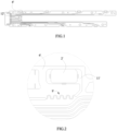
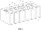
- a fusing zone is usually provided in the sampling circuit of the FPC (as shown in FIG. 1 and FIG. 2 , 11' is the sampling end portion of the sampling circuit,12' is the outputting end portion of the sampling circuit, S' is the fusing zone, 2 ' is the pad, 6' is the insulating film).
- 11' is the sampling end portion of the sampling circuit
- 12' is the outputting end portion of the sampling circuit
- S' is the fusing zone
- 2 ' is the pad
- 6' is the insulating film
- an object of the present invention is to provide a circuit board, a using method of the circuit board, a battery module and a vehicle, the circuit board has a simple structure and can be reused, thereby improving the utilization of the battery module.
- the present invention is defined in the independent claims.
- the present invention provides a circuit board as set out in claim 1.
- the second branch path is provided as one or multiple in number.
- the sampling circuits is provided as one or multiple in number.
- a protective adhesive is attached to a surface of the second pad.
- the present invention further provides a using method of a circuit board as set out in claim 5.
- the present invention further provides a battery module as set out in claim 6.
- the present invention further provides a vehicle as set out in claim 7.
- the present invention has the following beneficial effects: during the sampling process of the circuit board, the first pad transmits the collected signal to the external controller via the sampling end portion of the sampling circuit, the first branch path and the outputting end portion.
- the first fusing zone of the first branch path is fused (at this time the sampling end portion of the sampling circuit and the outputting end portion are disconnected)
- the circuit board can be quickly repaired by means of the second branch path and the second pad to electrically connect the sampling end portion and the outputting end portion during the return repair of the battery module, thereby achieving the purpose of reusing the circuit board, therefore the entire battery module is not scrapped and the utilization of the battery module is improved.
- the second fusing zone of the second branch path is used to protect the circuit board and the battery module again.
- the terms “first”, “second”, “third” are only used for illustrative purposes and are not to be construed as expressing or implying a relative importance.
- the term “plurality” is two or more.
- the terms “connect”, “fix” should be broadly interpreted, for example, the term “connect” can be “fixedly connect”, “detachably connect”, “integrally connect”, “electrically connect” or “signal connect”.
- the term “connect” also can be “directly connect” or “indirectly connect via a medium”.
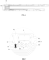
- a vehicle of the present invention comprises a battery module, and the battery module comprises a plurality of batteries 2, a circuit board 1, a plurality of electrical connecting sheets 3 and a conductive sheet 4.
- the plurality of batteries 2 are arranged side by side and electrically connected together by the plurality of electrical connecting sheets 3.
- the number of the conductive sheets 4 can be provided according to the number of the batteries 2 which are collected in temperature and/or voltage.
- the circuit board 1 is provided above the plurality of batteries 2 and electrically connected with the corresponding electrical connecting sheet 3 via the corresponding conductive sheet 4 to collect the temperature and/or voltage of the corresponding battery 2.
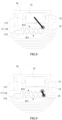
- the circuit board 1 may be a flexible printed circuit (abbreviated as FPC). Specifically, referring to FIG. 3 to FIG. 9 , the circuit board 1 comprises a conductive layer, a first pad 12, a second pad 13, a third pad 14, a conductive connecting member 15 and an insulating film 16.
- FPC flexible printed circuit
- the conductive layer of the circuit board 1 may be made of a metal material (such as a copper foil or an aluminum foil), and the conductive layer may be formed with one or multiple sampling circuits 11. Each sampling circuit 11 is electrically connected with the corresponding electrical connecting sheet 3 via the corresponding conductive sheet 4 to collect the temperature and/or voltage of the corresponding battery 2.
- the sampling circuit 11 comprises: a sampling end portion 111; an outputting end portion 112 connected with an external controller; a first branch path 113 connected with the sampling end portion 111 and the outputting end portion 112 and formed with a first fusing zone S11; and a second branch path 114 formed with a second fusing zone S12, one end of the second branch path 114 is connected with a portion of the first branch path 113 except the first fusing zone S11,and the other end of the second branch path 114 is spaced apart from the sampling end portion 111 and the first branch path 113.
- the first pad 12 is provided on the sampling end portion 111 of the sampling circuit 11 and connected with the conductive sheet 4 to collect the temperature and/or voltage of the battery 2.
- the second pad 13 is provided on the other end of the second branch path 114. The first pad 12 and the second pad 13 are identical with the sampling circuit 11 in number.
- the first pad 12 transmits the collected signal to the external controller via the sampling end portion 111, the first branch path 113 and the outputting end portion 112 of the sampling circuit 11.
- the first fusing zone S11 of the first branch path 113 is fused (at this time the sampling end portion 111 and the outputting end portion 112 of the sampling circuit 11 are disconnected)
- the circuit board 1 can be quickly repaired by means of the second branch path 114 and the second pad 13 to electrically connect the sampling end portion 111 and the outputting end portion 112 during the return repair of the battery module, thereby achieving the purpose of reusing the circuit board 1, therefore the entire battery module is not scrapped and the utilization of the battery module is improved.
- the second fusing zone S12 of the second branch path 114 is used to protect the circuit board 1 and the battery module again.
- the second branch path 114 may be manufactured in the same manufacturing process as the first branch path 113 to simplify the manufacturing process and improve the production efficiency of the circuit board 1. Moreover, the second branch path 114 is not limited to one in number and may be provided as multiple depending on the size of the circuit board 1.
- the quickly repair methods of the circuit board 1 repaired by the second branch path 114 and the second pad 13 during the return repair of the battery module are as follows, and the third pad 14 can be selectively provided based on different repair methods which are specifically described below.
- the second pad 13 is connected to the first pad 12 via the conductive connecting member 15, and at this time the sampling end portion 111 is electrically connected with the outputting end portion 112 via the first pad 12, the conductive connecting member 15, the second pad 13 and the second branch path 114 in sequence.
- the conductive connecting member 15 directly connects the second pad 13 and the first pad 12, it is not necessary to provide the third pad 14, thereby simplifying the structure and manufacturing process of the circuit board 1.
- the one end of the second branch path 114 is connected to the first branch path 113 at a position between the outputting end portion 112 and the first fusing zone S11, so as to make the second pad 13 provided on the other end of the second branch path 114 close to the first pad 12.
- the one end of the second branch path 114 is directly connected to the sampling end portion 111 or is connected to the first branch path 113 at a position between the sampling end portion 111 and the first fusing zone S11, and the third pad 14 is provided between the first fusing zone S11 and the outputting end portion 112, so as to make the third pad 14 close to the second pad 13, thereby helping to reduce the length of the conductive connecting member 15.
- the second pad 13 is connected to the third pad 14 via the conductive connecting member 15, and at this time the sampling end portion 111 is electrically connected to the outputting end portion 112 via the second branch path 114, the second pad 13, the conductive connecting member 15, the third pad 14 and the outputting end portion 112 in sequence.
- the formation position of the second branch path 114 does not need to depend on the position of the first pad 12, and at the same time because the conductive connecting member 15 is not directly connected to the first pad 12, thereby avoiding the effect of multiple connections (e.g., welding) on the first pad 12 (which is subsequently connected to the conductive sheet 4).
- the one end of the second branch path 114 is connected to the first branch path 113 at a position between the outputting end portion 112 and the first fusing zone S11, and the third pad 14 is provided between the first fusing zone S11 and the sampling end portion 111, so as to make the third pad 14 close to the second pad 13, thereby helping to reduce the length of the conductive connecting member 15.
- the second pad 13 is connected to the third pad 14 via the conductive connecting member 15, and at the same time the sampling end portion 111 is electrically connected to the outputting end portion 112 via the third pad 14, the conductive connecting member 15, the second pad 13 and the second branch path 114 in sequence.
- the formation position of the second branch path 114 does not need to depend on the position of the first pad 12, and at the same time because the conductive connecting member 15 is not directly connected to the first pad 12, thereby avoiding the effect of multiple connections on the first pad 12.
- the first pad 12, the second pad 13 and the third pad 14 may be integrally formed with the sampling circuit 11, or the first pad 12, the second pad 13 and the third pad 14 may be made of the same material as the sampling circuit 11 and connected to the sampling circuit 11 (e.g., welded, electrically bonded, press jointed etc.), or the first pad 12, the second pad 13 and the third pad 14 may be made of a metal material or an alloy material different from the sampling circuit 11 and connected to the sampling circuit 11.
- the shapes of the first pad 12, the second pad 13 and the third pad 14 may be circular, elliptical, square and the like.
- the conductive connecting member 15 is made of a metal material, the conductive connecting member 15 may specifically be a conductive wire, an aluminum wire, a copper wire, a nickel wire, a soldering tin and the like, and the connection method among the conductive connecting member15, the first pad 12 and the second pad 13 or among the conductive connecting member15, the second pad 13 and the third pad 14 may be welding, electrically bonding, press jointing and the like.
- an outer side of the conductive layer is covered with the insulating film 16.
- the first pad 12, the second pad 13 and the third pad 14 are exposed on the insulating film 16 to facilitate connection of them with other electrical connection members.
- the circuit board 1 comprises a conductive layer, a first pad 12, a second pad 13 and a third pad 14.
- the conductive layer is formed with a sampling circuit 11, and the sampling circuit 11 comprises: a sampling end portion 111; an outputting end portion 112; a first branch path 113 connected with the sampling end portion 111 and the outputting end portion 112 and formed with a first fusing zone S11; and a second branch path 114 formed with a second fusing zone S12, one end of the second branch path 114 is connected with a portion of the first branch path 113 except the first fusing zone S11, and the other end of the second branch path 114 is spaced apart from the sampling end portion 111 and the first branch path 113.
- the first pad 12 is provided on the sampling end portion 111
- the second pad 13 is provided on the other end of the second branch path 114
- the third pad 14 is provided at one side of the first fusing zone S11 of the first branch path 113.
- the claimed using method of the circuit board 1 comprises steps of: after the first fusing zone S11 of the first branch path 113 is fused, making the second pad 13 connected to the first pad 12 via a conductive connecting member 15, to make the second fusing zone S12 of the second branch path 114 electrically connected to the sampling end portion 111 and the outputting end portion 112;or after the first fusing zone S11 of the first branch path 113 is fused, making the second pad 13 connected to the third pad 14 via a conductive connecting member 15, to make the second fusing zone S12 of the second branch path 114 electrically connected to the sampling end portion 111 and the outputting end portion 112.
Landscapes
- Engineering & Computer Science (AREA)
- Microelectronics & Electronic Packaging (AREA)
- Chemical & Material Sciences (AREA)
- Chemical Kinetics & Catalysis (AREA)
- Electrochemistry (AREA)
- General Chemical & Material Sciences (AREA)
- Manufacturing & Machinery (AREA)
- Battery Mounting, Suspending (AREA)
- Combinations Of Printed Boards (AREA)
- Connection Of Batteries Or Terminals (AREA)
Claims (8)
- Leiterplatte (1), die Folgendes umfasst:eine leitfähige Schicht, die mit einer Abtastschaltung (11) ausgebildet ist, wobei die Abtastschaltung (11) Folgendes umfasst: einen Abtastendeabschnitt (111); einen Ausgabeendeabschnitt (112); einen ersten Zweigpfad (113), der mit dem Abtastendeabschnitt (111) und dem Ausgabeendeabschnitt (112) verbunden ist und mit einer ersten Schmelzzone (S11) ausgebildet ist; und einen zweiten Zweigpfad (114), der mit einer zweiten Schmelzzone (S12) ausgebildet ist,wobei ein Ende des zweiten Zweigpfads (114) mit einem Abschnitt des ersten Zweigpfads (113) außer der ersten Schmelzzone (S11) verbunden ist und das andere Ende des zweiten Zweigpfads (114) von dem Abtastendeabschnitt (111) und dem ersten Zweigpfad (113) beabstandet ist;wobei das eine Ende des zweiten Zweigpfads (114) an einer Stelle zwischen dem Ausgabeendeabschnitt (112) und der ersten Schmelzzone (S11) mit dem ersten Zweigpfad (113) verbunden ist und an dem anderen Ende des zweiten Zweigpfads (114) ein zweites Pad (13) bereitgestellt ist; wobei die Leiterplatte dadurch gekennzeichnet ist, dass an dem Abtastendeabschnitt (111) ein erstes Pad (12) bereitgestellt ist;wobei die erste Schmelzzone (S11) des ersten Zweigpfads (113) derart geschmolzen ist, dass der Abtastendeabschnitt (111) der Abtastschaltung (11) und der Ausgabeendeabschnitt (112) getrennt sind, das zweite Pad (13) über ein leitfähiges Verbindungselement (15) mit dem ersten Pad (12) verbunden ist, sodass der Abtastendeabschnitt (111) über das erste Pad (12), das leitfähige Verbindungselement (15), das zweite Pad (13) und den zweiten Zweigpfad (114) mit dem Ausgabeendeabschnitt (112) elektrisch in Reihe geschaltet ist.
- Leiterplatte (1) nach Anspruch 1, wobei der zweite Zweigpfad (114) als einer oder mehrere in der Zahl bereitgestellt ist.
- Leiterplatte (1) nach Anspruch 1, wobei die Abtastschaltung (11) als eine oder mehrere in der Zahl bereitgestellt ist.
- Verwendungsverfahren für die Leiterplatte (1), die eine mit einer Abtastschaltung (11) ausgebildete leitfähige Schicht umfasst, wobei die Abtastschaltung (11) Folgendes umfasst: einen Abtastendeabschnitt (111); einen Ausgabeendeabschnitt (112); einen ersten Zweigpfad (113), der mit dem Abtastendeabschnitt (111) und dem Ausgabeendeabschnitt (112) verbunden ist und mit einer ersten Schmelzzone (S11) ausgebildet ist; und einen zweiten Zweigpfad (114), der mit einer zweiten Schmelzzone (S12) ausgebildet ist, wobei ein Ende des zweiten Zweigpfads (114) mit einem Abschnitt des ersten Zweigpfads (113) außer der ersten Schmelzzone (S11) verbunden ist und das andere Ende des zweiten Zweigpfads (114) von dem Abtastendeabschnitt (111) und dem ersten Zweigpfad (113) beabstandet ist; wobei an dem Abtastendeabschnitt (11) ein erstes Pad (12) bereitgestellt ist;wobei das eine Ende des zweiten Zweigpfads (114) an einer Stelle zwischen dem Ausgabeendeabschnitt (112) und der ersten Schmelzzone (S11) mit dem ersten Zweigpfad (113) verbunden ist und an dem anderen Ende des zweiten Zweigpfads (114) ein zweites Pad (13) bereitgestellt ist; wobei die erste Schmelzzone (S11) des ersten Zweigpfads (113) derart geschmolzen ist, dass der Abtastendeabschnitt (111) der Abtastschaltung (11) und der Ausgabeendeabschnitt (112) getrennt sind;wobei das Verwendungsverfahren für die Leiterplatte (1) die folgenden Schritte umfasst: Verbinden des zweiten Pads (13) mit dem ersten Pad (12) über ein leitfähiges Verbindungselement (15), um die zweite Schmelzzone (S12) des zweiten Zweigpfads (114) mit dem Abtastendeabschnitt (111) und dem Ausgabeendeabschnitt (112) elektrisch zu verbinden, wobei der Abtastendeabschnitt (111) über das erste Pad (12), das leitfähige Verbindungselement (15), das zweite Pad (13) und den zweiten Zweigpfad (114) mit dem Ausgabeendeabschnitt (112) elektrisch in Reihe geschaltet wird.
- Verwendungsverfahren nach Anspruch 4, wobei der zweite Zweigpfad (114) als einer oder mehrere in der Zahl bereitgestellt ist.
- Verwendungsverfahren nach Anspruch 4, wobei die Abtastschaltung (11) als eine oder mehrere in der Zahl bereitgestellt ist.
- Batteriemodul, umfassend die Leiterplatte (1) nach einem der Ansprüche 1-3.
- Fahrzeug, umfassend das Batteriemodul nach Anspruch 7.
Applications Claiming Priority (1)
| Application Number | Priority Date | Filing Date | Title |
|---|---|---|---|
| CN201822168936.1U CN209787546U (zh) | 2018-12-23 | 2018-12-23 | 电路板及电池模组 |
Publications (2)
| Publication Number | Publication Date |
|---|---|
| EP3672377A1 EP3672377A1 (de) | 2020-06-24 |
| EP3672377B1 true EP3672377B1 (de) | 2025-05-14 |
Family
ID=68501353
Family Applications (1)
| Application Number | Title | Priority Date | Filing Date |
|---|---|---|---|
| EP19207858.2A Active EP3672377B1 (de) | 2018-12-23 | 2019-11-08 | Leiterplatte und verwendungsverfahren dafür, batteriemodul und fahrzeug |
Country Status (4)
| Country | Link |
|---|---|
| US (1) | US11335960B2 (de) |
| EP (1) | EP3672377B1 (de) |
| CN (1) | CN209787546U (de) |
| WO (1) | WO2020134981A1 (de) |
Families Citing this family (16)
| Publication number | Priority date | Publication date | Assignee | Title |
|---|---|---|---|---|
| KR102718016B1 (ko) * | 2020-05-07 | 2024-10-15 | 컨템포러리 엠퍼렉스 테크놀로지 (홍콩) 리미티드 | 전지 모듈, 전지 팩, 전지 모듈을 전원으로 사용하는 기기 및 전지 모듈의 제조 방법 |
| KR102745197B1 (ko) | 2020-07-28 | 2024-12-23 | 주식회사 엘지에너지솔루션 | Fpcb 및 그의 제조 방법 |
| CN214706024U (zh) * | 2021-03-30 | 2021-11-12 | 比亚迪股份有限公司 | 采样结构、电池包和电动车 |
| CN115189104B (zh) | 2021-04-06 | 2024-11-08 | 莫仕连接器(成都)有限公司 | 电池连接模组 |
| CN113346183B (zh) * | 2021-05-12 | 2023-05-05 | 中创新航技术研究院(江苏)有限公司 | 电池组、电池模组及电池包 |
| WO2023044243A1 (en) * | 2021-09-14 | 2023-03-23 | Inventus Power, Inc. | Conformal wearable battery |
| CN116632461A (zh) | 2022-02-11 | 2023-08-22 | 莫仕连接器(成都)有限公司 | 电池连接模组 |
| US12506215B2 (en) | 2022-03-23 | 2025-12-23 | Ford Global Technologies, Llc | Enclosure cover attachment configurations for traction battery packs with cell-to-pack battery systems |
| US12374750B2 (en) | 2022-03-23 | 2025-07-29 | Ford Global Technologies, Llc | Traction battery pack assembling method |
| US12275298B2 (en) | 2022-03-23 | 2025-04-15 | Ford Global Technologies, Llc | Traction battery packs with cell-to-pack battery systems housed within irregularly shaped enclosures |
| US12479327B2 (en) | 2022-03-23 | 2025-11-25 | Ford Global Technologies, Llc | Traction battery pack cell stack removal method and battery pack assembly |
| US12230826B2 (en) | 2022-03-23 | 2025-02-18 | Ford Global Technologies, Llc | Methods for assembling traction battery packs |
| US12525637B2 (en) | 2022-03-23 | 2026-01-13 | Ford Global Technologies, Llc | Traction battery pack assembling method |
| US12424695B2 (en) | 2022-03-23 | 2025-09-23 | Ford Global Technologies, Llc | Retention assemblies for traction battery packs with cell-to-pack battery systems |
| USD998576S1 (en) * | 2022-09-12 | 2023-09-12 | Jiarui Zhu | Flexible printed circuit board |
| CN115911720A (zh) * | 2022-11-18 | 2023-04-04 | 广州小鹏汽车科技有限公司 | 电池包及车辆 |
Family Cites Families (8)
| Publication number | Priority date | Publication date | Assignee | Title |
|---|---|---|---|---|
| DE1905490A1 (de) | 1969-02-05 | 1970-08-20 | Kienzle Apparate Gmbh | Mehrfach-Schmelzsicherung |
| JPS56114572U (de) | 1980-02-01 | 1981-09-03 | ||
| CN203968491U (zh) | 2013-12-31 | 2014-11-26 | 深圳市比亚迪电子部品件有限公司 | 一种柔性印刷线路板 |
| CN204011598U (zh) | 2014-06-30 | 2014-12-10 | 比亚迪股份有限公司 | 信号采集模块和具有其的电池系统 |
| CN204243156U (zh) | 2014-06-30 | 2015-04-01 | 深圳市比亚迪锂电池有限公司 | 信号采集模块和具有其的电池系统 |
| CN112888159B (zh) | 2017-01-09 | 2022-10-25 | 莫仕连接器(成都)有限公司 | 电池连接模块 |
| CN207502073U (zh) | 2017-09-29 | 2018-06-15 | 江苏由甲申田新能源科技有限公司 | 温度传感器 |
| CN208754586U (zh) | 2018-05-08 | 2019-04-16 | 东莞市硅翔绝缘材料有限公司 | 用于动力电池的轻量化信号采集fpc |
-
2018
- 2018-12-23 CN CN201822168936.1U patent/CN209787546U/zh active Active
-
2019
- 2019-11-04 US US16/673,534 patent/US11335960B2/en active Active
- 2019-11-08 EP EP19207858.2A patent/EP3672377B1/de active Active
- 2019-12-06 WO PCT/CN2019/123696 patent/WO2020134981A1/zh not_active Ceased
Also Published As
| Publication number | Publication date |
|---|---|
| CN209787546U (zh) | 2019-12-13 |
| EP3672377A1 (de) | 2020-06-24 |
| WO2020134981A1 (zh) | 2020-07-02 |
| US20200203777A1 (en) | 2020-06-25 |
| US11335960B2 (en) | 2022-05-17 |
Similar Documents
| Publication | Publication Date | Title |
|---|---|---|
| EP3672377B1 (de) | Leiterplatte und verwendungsverfahren dafür, batteriemodul und fahrzeug | |
| US11894580B2 (en) | Battery interconnects | |
| JP6344705B2 (ja) | バッテリーパック、回路基板および回路基板の連結方法 | |
| US11791577B2 (en) | Forming connections to flexible interconnect circuits | |
| WO2017062886A1 (en) | Battery interconnects | |
| JP5782013B2 (ja) | フレキシブルプリント基板の接合方法 | |
| EP3102000A1 (de) | Gestapelte platte für fenster und verfahren zur herstellung der gestapelten platte für fenster | |
| CN107995775B (zh) | 自带过流保护柔性电路及制造工艺 | |
| JP2018094949A (ja) | 車両用窓ガラス及び車両用窓ガラスの製造方法 | |
| US12212107B2 (en) | Flat connector for soldering on laminated glass | |
| CN217336015U (zh) | 一种软硬结合线路板结构 | |
| CN117528956A (zh) | 一种无smt的高可靠性低成本采集集成母排及其制备方法 | |
| US10991929B2 (en) | Strain relief for flex foil | |
| JP4028160B2 (ja) | フレキシブル基板の端子構造及びその製造方法 | |
| CN114864189A (zh) | 一种制造排线的方法以及排线 | |
| CN112584602A (zh) | 柔性电路板、电池装置和电池装置的组装方法 | |
| CN116113165B (zh) | 一种动力电池组信号采样组件的镂空加工方法 | |
| CN222927710U (zh) | 电池采样组件及电池包 | |
| CN121123576A (zh) | 一种集成母排及其加工方法 | |
| CN119253209A (zh) | 绝缘件、电芯及其制造方法和用电设备 | |
| CN119852660A (zh) | 采样单元、采样组件以及电池包 | |
| CN114641130A (zh) | 一种软硬结合线路板结构及其制备工艺 | |
| JP2016096132A (ja) | フラットケーブル接続構造体 | |
| CN120962030A (zh) | 集成母排的制作方法及集成母排 | |
| CN120954786A (zh) | Ffc线、汽车及ffc线的制造方法 |
Legal Events
| Date | Code | Title | Description |
|---|---|---|---|
| PUAI | Public reference made under article 153(3) epc to a published international application that has entered the european phase |
Free format text: ORIGINAL CODE: 0009012 |
|
| STAA | Information on the status of an ep patent application or granted ep patent |
Free format text: STATUS: REQUEST FOR EXAMINATION WAS MADE |
|
| 17P | Request for examination filed |
Effective date: 20191108 |
|
| AK | Designated contracting states |
Kind code of ref document: A1 Designated state(s): AL AT BE BG CH CY CZ DE DK EE ES FI FR GB GR HR HU IE IS IT LI LT LU LV MC MK MT NL NO PL PT RO RS SE SI SK SM TR |
|
| AX | Request for extension of the european patent |
Extension state: BA ME |
|
| STAA | Information on the status of an ep patent application or granted ep patent |
Free format text: STATUS: EXAMINATION IS IN PROGRESS |
|
| 17Q | First examination report despatched |
Effective date: 20231006 |
|
| REG | Reference to a national code |
Ref country code: DE Ref legal event code: R079 Ipc: H01M0010480000 Ref country code: DE Ref legal event code: R079 Ref document number: 602019069911 Country of ref document: DE Free format text: PREVIOUS MAIN CLASS: H05K0001020000 Ipc: H01M0010480000 |
|
| RAP1 | Party data changed (applicant data changed or rights of an application transferred) |
Owner name: CONTEMPORARY AMPEREX TECHNOLOGY(HONG KONG) LIMITED |
|
| RIC1 | Information provided on ipc code assigned before grant |
Ipc: H05K 1/18 20060101ALI20240822BHEP Ipc: H05K 1/02 20060101ALI20240822BHEP Ipc: H01M 10/48 20060101AFI20240822BHEP |
|
| GRAP | Despatch of communication of intention to grant a patent |
Free format text: ORIGINAL CODE: EPIDOSNIGR1 |
|
| STAA | Information on the status of an ep patent application or granted ep patent |
Free format text: STATUS: GRANT OF PATENT IS INTENDED |
|
| INTG | Intention to grant announced |
Effective date: 20250115 |
|
| GRAS | Grant fee paid |
Free format text: ORIGINAL CODE: EPIDOSNIGR3 |
|
| GRAA | (expected) grant |
Free format text: ORIGINAL CODE: 0009210 |
|
| STAA | Information on the status of an ep patent application or granted ep patent |
Free format text: STATUS: THE PATENT HAS BEEN GRANTED |
|
| AK | Designated contracting states |
Kind code of ref document: B1 Designated state(s): AL AT BE BG CH CY CZ DE DK EE ES FI FR GB GR HR HU IE IS IT LI LT LU LV MC MK MT NL NO PL PT RO RS SE SI SK SM TR |
|
| REG | Reference to a national code |
Ref country code: GB Ref legal event code: FG4D |
|
| REG | Reference to a national code |
Ref country code: CH Ref legal event code: EP |
|
| P01 | Opt-out of the competence of the unified patent court (upc) registered |
Free format text: CASE NUMBER: APP_19273/2025 Effective date: 20250422 |
|
| REG | Reference to a national code |
Ref country code: IE Ref legal event code: FG4D |
|
| REG | Reference to a national code |
Ref country code: DE Ref legal event code: R096 Ref document number: 602019069911 Country of ref document: DE |
|
| REG | Reference to a national code |
Ref country code: NL Ref legal event code: MP Effective date: 20250514 |
|
| PG25 | Lapsed in a contracting state [announced via postgrant information from national office to epo] |
Ref country code: FI Free format text: LAPSE BECAUSE OF FAILURE TO SUBMIT A TRANSLATION OF THE DESCRIPTION OR TO PAY THE FEE WITHIN THE PRESCRIBED TIME-LIMIT Effective date: 20250514 Ref country code: ES Free format text: LAPSE BECAUSE OF FAILURE TO SUBMIT A TRANSLATION OF THE DESCRIPTION OR TO PAY THE FEE WITHIN THE PRESCRIBED TIME-LIMIT Effective date: 20250514 Ref country code: PT Free format text: LAPSE BECAUSE OF FAILURE TO SUBMIT A TRANSLATION OF THE DESCRIPTION OR TO PAY THE FEE WITHIN THE PRESCRIBED TIME-LIMIT Effective date: 20250915 |
|
| REG | Reference to a national code |
Ref country code: LT Ref legal event code: MG9D |
|
| PG25 | Lapsed in a contracting state [announced via postgrant information from national office to epo] |
Ref country code: NO Free format text: LAPSE BECAUSE OF FAILURE TO SUBMIT A TRANSLATION OF THE DESCRIPTION OR TO PAY THE FEE WITHIN THE PRESCRIBED TIME-LIMIT Effective date: 20250814 Ref country code: GR Free format text: LAPSE BECAUSE OF FAILURE TO SUBMIT A TRANSLATION OF THE DESCRIPTION OR TO PAY THE FEE WITHIN THE PRESCRIBED TIME-LIMIT Effective date: 20250815 |
|
| PG25 | Lapsed in a contracting state [announced via postgrant information from national office to epo] |
Ref country code: NL Free format text: LAPSE BECAUSE OF FAILURE TO SUBMIT A TRANSLATION OF THE DESCRIPTION OR TO PAY THE FEE WITHIN THE PRESCRIBED TIME-LIMIT Effective date: 20250514 Ref country code: PL Free format text: LAPSE BECAUSE OF FAILURE TO SUBMIT A TRANSLATION OF THE DESCRIPTION OR TO PAY THE FEE WITHIN THE PRESCRIBED TIME-LIMIT Effective date: 20250514 |
|
| REG | Reference to a national code |
Ref country code: AT Ref legal event code: MK05 Ref document number: 1795612 Country of ref document: AT Kind code of ref document: T Effective date: 20250514 |
|
| PG25 | Lapsed in a contracting state [announced via postgrant information from national office to epo] |
Ref country code: BG Free format text: LAPSE BECAUSE OF FAILURE TO SUBMIT A TRANSLATION OF THE DESCRIPTION OR TO PAY THE FEE WITHIN THE PRESCRIBED TIME-LIMIT Effective date: 20250514 |
|
| PG25 | Lapsed in a contracting state [announced via postgrant information from national office to epo] |
Ref country code: HR Free format text: LAPSE BECAUSE OF FAILURE TO SUBMIT A TRANSLATION OF THE DESCRIPTION OR TO PAY THE FEE WITHIN THE PRESCRIBED TIME-LIMIT Effective date: 20250514 |
|
| PG25 | Lapsed in a contracting state [announced via postgrant information from national office to epo] |
Ref country code: AT Free format text: LAPSE BECAUSE OF FAILURE TO SUBMIT A TRANSLATION OF THE DESCRIPTION OR TO PAY THE FEE WITHIN THE PRESCRIBED TIME-LIMIT Effective date: 20250514 |
|
| PG25 | Lapsed in a contracting state [announced via postgrant information from national office to epo] |
Ref country code: RS Free format text: LAPSE BECAUSE OF FAILURE TO SUBMIT A TRANSLATION OF THE DESCRIPTION OR TO PAY THE FEE WITHIN THE PRESCRIBED TIME-LIMIT Effective date: 20250814 |
|
| PG25 | Lapsed in a contracting state [announced via postgrant information from national office to epo] |
Ref country code: IS Free format text: LAPSE BECAUSE OF FAILURE TO SUBMIT A TRANSLATION OF THE DESCRIPTION OR TO PAY THE FEE WITHIN THE PRESCRIBED TIME-LIMIT Effective date: 20250914 |
|
| PG25 | Lapsed in a contracting state [announced via postgrant information from national office to epo] |
Ref country code: LV Free format text: LAPSE BECAUSE OF FAILURE TO SUBMIT A TRANSLATION OF THE DESCRIPTION OR TO PAY THE FEE WITHIN THE PRESCRIBED TIME-LIMIT Effective date: 20250514 |
|
| PGFP | Annual fee paid to national office [announced via postgrant information from national office to epo] |
Ref country code: DE Payment date: 20251124 Year of fee payment: 7 |
|
| PGFP | Annual fee paid to national office [announced via postgrant information from national office to epo] |
Ref country code: GB Payment date: 20251126 Year of fee payment: 7 |
|
| PG25 | Lapsed in a contracting state [announced via postgrant information from national office to epo] |
Ref country code: SM Free format text: LAPSE BECAUSE OF FAILURE TO SUBMIT A TRANSLATION OF THE DESCRIPTION OR TO PAY THE FEE WITHIN THE PRESCRIBED TIME-LIMIT Effective date: 20250514 Ref country code: DK Free format text: LAPSE BECAUSE OF FAILURE TO SUBMIT A TRANSLATION OF THE DESCRIPTION OR TO PAY THE FEE WITHIN THE PRESCRIBED TIME-LIMIT Effective date: 20250514 |
|
| PGFP | Annual fee paid to national office [announced via postgrant information from national office to epo] |
Ref country code: FR Payment date: 20251128 Year of fee payment: 7 |
|
| PG25 | Lapsed in a contracting state [announced via postgrant information from national office to epo] |
Ref country code: CZ Free format text: LAPSE BECAUSE OF FAILURE TO SUBMIT A TRANSLATION OF THE DESCRIPTION OR TO PAY THE FEE WITHIN THE PRESCRIBED TIME-LIMIT Effective date: 20250514 |
|
| PG25 | Lapsed in a contracting state [announced via postgrant information from national office to epo] |
Ref country code: EE Free format text: LAPSE BECAUSE OF FAILURE TO SUBMIT A TRANSLATION OF THE DESCRIPTION OR TO PAY THE FEE WITHIN THE PRESCRIBED TIME-LIMIT Effective date: 20250514 |
|
| PG25 | Lapsed in a contracting state [announced via postgrant information from national office to epo] |
Ref country code: RO Free format text: LAPSE BECAUSE OF FAILURE TO SUBMIT A TRANSLATION OF THE DESCRIPTION OR TO PAY THE FEE WITHIN THE PRESCRIBED TIME-LIMIT Effective date: 20250514 Ref country code: SK Free format text: LAPSE BECAUSE OF FAILURE TO SUBMIT A TRANSLATION OF THE DESCRIPTION OR TO PAY THE FEE WITHIN THE PRESCRIBED TIME-LIMIT Effective date: 20250514 |
|
| PG25 | Lapsed in a contracting state [announced via postgrant information from national office to epo] |
Ref country code: IT Free format text: LAPSE BECAUSE OF FAILURE TO SUBMIT A TRANSLATION OF THE DESCRIPTION OR TO PAY THE FEE WITHIN THE PRESCRIBED TIME-LIMIT Effective date: 20250514 |