EP3672150A1 - Steckeraufnahme zur gleichzeitigen übertragung von daten und gleichspannung - Google Patents
Steckeraufnahme zur gleichzeitigen übertragung von daten und gleichspannung Download PDFInfo
- Publication number
- EP3672150A1 EP3672150A1 EP19215887.1A EP19215887A EP3672150A1 EP 3672150 A1 EP3672150 A1 EP 3672150A1 EP 19215887 A EP19215887 A EP 19215887A EP 3672150 A1 EP3672150 A1 EP 3672150A1
- Authority
- EP
- European Patent Office
- Prior art keywords
- contact
- data
- input contact
- voltage
- output contact
- Prior art date
- Legal status (The legal status is an assumption and is not a legal conclusion. Google has not performed a legal analysis and makes no representation as to the accuracy of the status listed.)
- Withdrawn
Links
- 230000005540 biological transmission Effects 0.000 title claims abstract description 21
- 230000008878 coupling Effects 0.000 claims abstract description 59
- 238000010168 coupling process Methods 0.000 claims abstract description 59
- 238000005859 coupling reaction Methods 0.000 claims abstract description 59
- 238000004891 communication Methods 0.000 claims description 8
- 239000004020 conductor Substances 0.000 description 5
- 238000013461 design Methods 0.000 description 2
- 238000009434 installation Methods 0.000 description 2
- 238000000034 method Methods 0.000 description 2
- 229910000679 solder Inorganic materials 0.000 description 2
- 239000003990 capacitor Substances 0.000 description 1
- 230000008859 change Effects 0.000 description 1
- 238000011161 development Methods 0.000 description 1
- 230000018109 developmental process Effects 0.000 description 1
- 230000002349 favourable effect Effects 0.000 description 1
- 238000001746 injection moulding Methods 0.000 description 1
- 230000008569 process Effects 0.000 description 1
- 238000012545 processing Methods 0.000 description 1
- 238000005476 soldering Methods 0.000 description 1
- 230000003595 spectral effect Effects 0.000 description 1
- 238000001228 spectrum Methods 0.000 description 1
- 230000007704 transition Effects 0.000 description 1
Images
Classifications
-
- H—ELECTRICITY
- H04—ELECTRIC COMMUNICATION TECHNIQUE
- H04L—TRANSMISSION OF DIGITAL INFORMATION, e.g. TELEGRAPHIC COMMUNICATION
- H04L12/00—Data switching networks
- H04L12/02—Details
- H04L12/10—Current supply arrangements
-
- H—ELECTRICITY
- H04—ELECTRIC COMMUNICATION TECHNIQUE
- H04B—TRANSMISSION
- H04B3/00—Line transmission systems
- H04B3/54—Systems for transmission via power distribution lines
- H04B3/548—Systems for transmission via power distribution lines the power on the line being DC
-
- H—ELECTRICITY
- H04—ELECTRIC COMMUNICATION TECHNIQUE
- H04B—TRANSMISSION
- H04B3/00—Line transmission systems
- H04B3/54—Systems for transmission via power distribution lines
- H04B3/56—Circuits for coupling, blocking, or by-passing of signals
-
- H—ELECTRICITY
- H04—ELECTRIC COMMUNICATION TECHNIQUE
- H04B—TRANSMISSION
- H04B3/00—Line transmission systems
- H04B3/54—Systems for transmission via power distribution lines
Definitions
- the invention relates to a connector receptacle for the simultaneous transmission of data and DC voltage, a module for the simultaneous transmission of data and DC voltage, a communication system for the simultaneous transmission of data and DC voltage and a motor vehicle.
- Plug receptacles for the simultaneous transmission of data and DC voltage are known in principle from the prior art.
- the publication DE 10 2013 012 368 A1 shows a motor vehicle electrical system and a method for transmitting data signals in a motor vehicle electrical system, wherein data that are provided by consumers are transmitted via supply lines.
- a connector receptacle for the simultaneous transmission of data and DC voltage, which is designed to accommodate a corresponding connector.
- the plug receptacle comprises a first data input contact, a first DC voltage input contact, a first coupling filter, and a first output contact.
- the first output contact is directly connected to the first data input contact and is electrically connected to the first DC voltage input contact via the first coupling filter.
- the simultaneous transmission of data and DC voltage means the transmission of data and electrical energy on a common electrical conductor.
- the data i.e. information
- the electrical signal which is also called the data signal, can be an analog signal or a digital signal.
- the data signal can for example, a voltage signal or a current signal.
- the voltage signal or the current signal is transmitted by modulating an electrical voltage or an electrical current.
- the data signal is an AC signal of a carrier frequency fc modulated by an information stream.
- the data signal usually occupies a predetermined frequency range, for example the frequency range f C -f B to f C + f B with a bandwidth of 2 ⁇ f B , in an electromagnetic spectrum. The greater the bandwidth of the data signal, the higher the requirements for a coupling between the DC voltage and the data signal.
- a DC voltage is an electrical voltage whose instantaneous value does not change over a longer period of time. It has the same sign and the same amount at all times.
- the transmission on a common electrical conductor takes place in that the data signal and the DC voltage are superimposed on one another.
- both the data and the electrical energy can be transmitted simultaneously on a single electrical conductor, for example on a single wire in a cable or on a single busbar.
- the connector receptacle is designed to receive a corresponding connector.
- the plug receptacle has, for example, a hollow shape, at least in sections, into which a corresponding plug can be inserted or inserted.
- the connector and the connector receptacle are aligned and fixed appropriately by positive locking.
- the plug receptacle can be non-positively fixed by means of locking elements, for example a locking lug, spring elements, for example a contact foot, or screw elements. If the corresponding plug is inserted into the plug receptacle, at least one electrical connection is closed, that is to say made conductive.
- the first data input contact is, for example, a pin, which can also be called a pin or contact pin, and which can be inserted into a circuit board.
- the first data input contact becomes electrical with a processing device connected, for example to a circuit on the board, which is designed to receive, process, and / or send data.
- the pure data signal without the DC voltage is present at the first data input contact.
- the first DC input contact is, for example, a pin that can be plugged into a circuit board.
- the first DC input contact and the first data input contact can be plugged into the circuit board at the same time.
- the first DC voltage input contact is connected to a DC voltage source.
- the first DC input contact can be electrically connected to a terminal 15.
- the pure DC voltage is present at the first DC voltage input contact without a data signal.
- the first coupling filter is an electrical circuit which influences the DC voltage signal as a function of the frequency in amplitude and phase position.
- the first coupling filter smoothes the DC voltage.
- the first coupling filter can electrically isolate the first DC input contact and the output contact.
- the first output contact comprises, for example, a cable clamp into which a cable can be clamped or screwed.
- the first output contact comprises a contact opening, which is designed to receive a corresponding pin of a plug.
- the first output contact comprises a pin, which is designed to engage in a corresponding contact opening of a plug.
- the first output contact can comprise a conductor, for example a pin. Since the first output contact is designed to receive at least part of a plug, the plug receptacle is designed to receive the plug. In other words, the first output contact contacts a part of a plug, for example a contact opening of the plug or a pin of the plug when the plug is in the plug receptacle.
- the first output contact is directly electrically connected to the first data input contact. This means that the first output contact and the first data input contact are connected to one another without the interposition of further electrical components.
- the first output contact and the first data input contact are made, for example, in one piece from a wire. Again, for example, the first output contact and the first data input contact share a common conductor. Again, for example, the first output contact and the first data input contact are soldered together. For example, the total common length of the first output contact and data input contact is less than two centimeters.
- the first output contact is electrically connected to the first DC input contact via the first coupling filter. This means that the first output contact and the first coupling filter are directly electrically connected, and that the first direct voltage input contact and the first coupling filter are directly electrically connected.
- the first output contact is electrically connected to an input and the first DC voltage input contact to an output of the first coupling filter.
- the smoothed DC voltage can be superimposed on the data signal without the DC voltage being influenced by interference.
- the first data input contact, the first DC voltage input contact and the first output contact each have a length that corresponds approximately to an extension of the plug receptacle, for example between half as long and twice as long as the plug receptacle.
- the connector receptacle a first data input contact, a first DC input contact, a first coupling filter, and a first Includes output contact
- the first coupling filter can be shielded electrically well from interference of the circuit board.
- the electrical connection between the DC voltage source, the first coupling filter and the first output contact can be particularly short and geometrically advantageous.
- the connector receptacle can be further developed in that the first coupling filter is encapsulated within the connector receptacle.
- the first coupling filter is surrounded by a structure which, apart from the coupling filter, only comprises parts of the first output contact and the first DC voltage input contact.
- the first coupling filter can be encapsulated in a chamber of the connector receptacle.
- the chamber can, for example, be an integral part of the plug receptacle.
- the first coupling filter can be encapsulated in its own housing within the connector receptacle.
- the structure which encapsulates the first coupling filter can have cutouts for a part of the first output contact and / or a part of the first DC voltage input contact. If the structure is produced by the injection molding process, for example the first output contact and / or the first DC voltage input contact can be cast in.
- the first coupling filter is encapsulated in the connector receptacle, the first coupling filter can be shielded particularly well from interference and the data signal can thus be transmitted particularly well.
- the connector receptacle can be further developed in that the first DC voltage input contact and the first data input contact are arranged parallel to one another, the first coupling filter being arranged in a region between the first DC voltage input contact and the first data input contact.
- the plug receptacle can be attached to a circuit board in a particularly simple manner, for example inserted into the circuit board. If the first coupling filter is arranged between the first direct voltage input contact and the first data input contact, the first direct voltage input contact and the first data input contact can be arranged particularly well separated from one another, the plug receptacle also being compact.
- the connector receptacle is further developed in that the first data input contact and the first output contact are arranged at a right angle to one another, the first coupling filter being electrically connected to the first output contact in a region of the angle.
- a right angle is an angle of approximately 90 degrees, for example 70 to 110 degrees, for example 85 to 95 degrees.
- the first data input contact and the first output contact can be connected to one another at such an angle, for example, butt after butt. Again, for example, the first data input contact and the first output contact to one another can essentially take up this angle, the first data input contact and the first output contact forming an arc in a transition region.
- the first output contact can terminate in an arc of 90 degrees at the end at which it is connected to the first data input contact.
- the first output contact has a curvature of 90 degrees at the end where the first output contact is connected, for example soldered, to the first data input contact.
- the first output contact has a curvature of 90 degrees at the end, where the first output contact merges into the first data input contact.
- the curvature has a radius of, for example, between 0% and 30% of the length of the data input contact, for example between 5% and 20%.
- the data input contact, the first DC voltage input contact and the first output contact are arranged on one level.
- the output contact points away from the first DC voltage input contact.
- the first coupling filter is electrically connected to the first output contact in a region of the angle, that is to say in a region of the electrical connection of the data input contact to the first output contact.
- a range of the angle means for example at a kink between the first data input contact and the first output contact, or in a solder joint between the first data input contact and the first output contact, or in a range of the curvature of the first output contact described above.
- a short distance from the kink or the solder joint means, for example, between 0% and 20% of the length of the first output contact, for example between 0% and 5% of the length of the first output contact.
- the first coupling filter is electrically connected to the first output contact at a range of an angle of approximately 90 degrees, the high-frequency properties of the plug receptacle are particularly favorable.
- the first coupling filter can thereby be arranged spatially in a particularly simple manner. Because the first data input contact, the first DC voltage input contact and the first output contact are arranged in one plane, additional contacts can be integrated in a plug receptacle particularly easily.
- the plug receptacle can be further developed in that the plug receptacle has a second output contact, the first output contact and the second output contact being designed to collectively accommodate a two-pole plug element.
- the second output contact can comprise a ground contact, or the second output contact can transmit an additional data signal.
- the two-pole connector element which can also be called a two-core connector element, can be, for example, a jack plug, a two-pole IEC connector, or a two-pole DIN connector.
- the second output contact can also simultaneously transmit data and DC voltage.
- the connector receptacle has, for example, a second data input contact.
- the plug receptacle can also have a second DC voltage input contact, or branch DC voltage at the first DC voltage input contact in the plug receptacle.
- the plug receptacle can also have a second coupling filter electrically connected to the second output contact.
- the first and the second coupling filter can each be encapsulated as described above.
- the plug receptacle By the plug receptacle comprising a second output contact, the plug receptacle can perform additional functions. Because the first output contact and the second output contact are designed to jointly accommodate a two-pole plug element, the plug receptacle can be designed to be particularly compact.
- the connector receptacle can be further developed in that the first output contact and the second output contact are designed to receive a coaxial connector element.
- the first output contact and the second output contact are designed, for example, to receive a FAKRA connector or an SMBA connector.
- the first output contact and the second output contact are designed to accommodate another coaxial connector element, for example an RCA connector, a cinch connector, a Belling-Lee connector, a BNC connector, an MCX connector, or an SMA connector. Plug.
- first output contact and the second output contact are designed to accommodate a coaxial connector element, particularly interference-free transmission of data and DC voltage can be achieved. You can also thereby the connector receptacle, a corresponding connector and corresponding cables are designed to be particularly compact.
- the connector receptacle can be further developed in that the first coupling filter comprises an inductor.
- the DC voltage is smoothed by the inductance.
- the first coupling filter has multiple inductors.
- the first coupling filter has inductors and capacitors.
- the first coupling filter comprises an inductance
- a module for the simultaneous transmission of data and DC voltage comprising a circuit board with a DC voltage source and a data source, and a connector receptacle according to one of the above-described embodiments, which is connected to the circuit board.
- the DC voltage source is electrically connected directly to the first DC voltage input contact of the connector receptacle.
- the data source is electrically connected directly to the first data input contact.
- the DC voltage source draws energy, for example, from a battery, an alternator or from a rectifier.
- the DC voltage source provides the almost constant voltage, for example +12 V ⁇ 1.5 V.
- the data source includes, for example, a processor and / or circuits that are designed to control vehicle functions.
- the data source comprises a data interface, for example a mobile radio interface.
- the data source is designed to send data, to receive data, or to send and receive data.
- the DC voltage source is connected directly to the first DC voltage input contact of the plug receptacle, for example by plugging the first DC voltage input contact into a spring contact of the DC voltage source or by, for example, clamping the DC voltage source to the first DC voltage input contact.
- the data source can be directly electrically connected to the first data input contact in the same way as the DC voltage source to the first DC voltage input contact. Alternatively, the data source can otherwise be directly electrically connected to the first data input contact.
- the data signal can be overlaid with the DC voltage largely without interference, and at the same time space can be saved in the module.
- the data signal can be routed to the output contact largely without interference and at the same time space can be saved.
- the module can be further developed in that the connector receptacle is permanently connected to the circuit board.
- unsolvable means that the connector receptacle cannot be detached from the board without being destroyed.
- the plug receptacle can be non-detachably connected to the circuit board by the first direct voltage input contact being non-detachably connected to a contact of the direct voltage source.
- the first data input contact can be permanently connected to a contact of the data source.
- a housing of the plug receptacle can be permanently connected to the circuit board.
- the connector receptacle can be an integral part of the board, that is, the connector receptacle and the board can be common components share.
- the connector receptacle can be glued to the circuit board.
- the connector receptacle can be made particularly robust and installation space can be saved.
- the module can be further developed by soldering the connector receptacle to the circuit board.
- the connector receptacle can be permanently connected to the circuit board by soldering the first DC voltage input contact to a contact of the DC voltage source.
- the first data input contact can be soldered to a contact of the data source.
- contact resistance between the contacts of the plug receptacle and the contacts of the circuit board can be particularly low, and further installation space can be saved.
- a communication system for the simultaneous transmission of data and DC voltage comprising a module according to one of the above-described embodiments, a control device and a connecting cable which is designed to electrically connect a plug receptacle of the module and the control device .
- the control device is designed to be supplied with direct voltage by the connecting cable and at the same time to exchange data with the module via the connecting cable.
- the communication system can meet particularly high requirements for the transmission of data and DC voltage, for example high electrical powers and a high spectral bandwidth for data transmission, for example several GHz bandwidth.
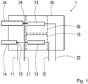
- Fig. 1 shows a schematic representation of a connector receptacle 1 according to at least one embodiment.
- the connector receptacle 1 comprises a first data input contact 11, a first DC voltage input contact 12, a first coupling filter 13 and a first output contact 14.
- the first data input contact 11 and the first output contact 14 are directly electrically connected to one another at a right angle 15.
- the first coupling filter 13 is also directly electrically connected to the first output contact 14 in a region of the angle 15.
- the first coupling filter 13 is directly electrically connected to the first direct voltage input contact 12 at a further end.
- the connector receptacle 1 comprises a second data input contact 21, a second DC voltage input contact 22, a second coupling filter 23 and a second output contact 24.
- the second data input contact 21 and the second output contact 24 are directly at a right angle 25 to one another electrically connected.
- the second coupling filter 23 is also directly electrically connected to the second output contact 24 in a region of the angle 25.
- the second coupling filter 23 is directly electrically connected at a further end to the second direct voltage input contact 22
- the connector receptacle 1 has a housing 30 which houses all the components and has cutouts for the first and second data input contacts 11 and 21, the first and second DC voltage input contacts 12 and 22, and the first and second output contacts 14 and 24.
- the first coupling filter 13 is encapsulated within the connector receptacle 1.
- the housing 30 comprises a first chamber 16.
- the first chamber 16 comprises cutouts, which can also be called openings, for a part of the first coupling filter 13, which is electrically connected to the first DC input contact 12, and for a part of the first coupling filter 13 , which is electrically connected to the first output contact 14.
- the second coupling filter 23 is encapsulated within the connector receptacle 1.
- the housing 30 comprises a second chamber 26.
- the second chamber 26 includes cutouts, which can also be called openings, for a part of the second coupling filter 23, which is electrically connected to the second DC voltage input contact 22, and for a part of the second coupling filter 23 , which is electrically connected to the second output contact 24.
- the first direct voltage input contact 12 and the first data input contact 11 are arranged parallel to one another.
- the first coupling filter 13 is arranged in a region between the first DC input contact 12 and the first data input contact 11.
- the second DC voltage input contact 22 and the second data input contact 21 are arranged parallel to one another, and the second coupling filter 23 is arranged in a region between the second DC voltage input contact 22 and the second data input contact 21.
- first output contact 14 and the second output contact 24 are designed to jointly accommodate a two-pole plug element.
- first output contact 14 and the second output contact 24 can receive an IEC connector.
Landscapes
- Engineering & Computer Science (AREA)
- Computer Networks & Wireless Communication (AREA)
- Signal Processing (AREA)
- Power Engineering (AREA)
- Details Of Connecting Devices For Male And Female Coupling (AREA)
Abstract
Steckeraufnahme (1) zur gleichzeitigen Übertragung von Daten und Gleichspannung, die ausgebildet ist einen korrespondierenden Stecker aufzunehmen, die einen Dateneingangskontakt (11), einen Gleichspannungseingangskontakt (12), ein Kopplungsfilter (13), und einen ersten Ausgangskontakt (14) umfasst, wobei der erste Ausgangskontakt mit dem ersten Dateneingangskontakt unmittelbar und mit dem ersten Gleichspannungseingangskontakt über das erste Kopplungsfilter elektrisch verbunden sind.
Description
- Die Erfindung betrifft eine Steckeraufnahme zur gleichzeitigen Übertragung von Daten und Gleichspannung, ein Modul zur gleichzeitigen Übertragung von Daten und Gleichspannung, ein Kommunikationssystem zur gleichzeitigen Übertragung von Daten und Gleichspannung und ein Kraftfahrzeug.
- Steckeraufnahmen zur gleichzeitigen Übertragung von Daten und Gleichspannung sind prinzipiell aus dem Stand der Technik bekannt. Die Druckschrift
DE 10 2013 012 368 A1 zeigt ein Kraftfahrzeug-Bordnetz sowie ein Verfahren zur Übertragung von Datensignalen in einem Kraftfahrzeug-Bordnetz, wobei Daten, die von Verbrauchern bereitgestellt werden, über Versorgungsleitungen übermittelt werden. - Es ist daher eine Aufgabe der vorliegenden Erfindung, eine verbesserte Steckeraufnahme zur gleichzeitigen Übertragung von Daten und Gleichspannung, ein verbessertes Modul zur gleichzeitigen Übertragung von Daten und Gleichspannung, ein verbessertes Kommunikationssystem zur gleichzeitigen Übertragung von Daten und Gleichspannung und ein verbessertes Kraftfahrzeug bereitzustellen.
- Diese Aufgabe wird gelöst durch eine Steckeraufnahme zur gleichzeitigen Übertragung von Daten und Gleichspannung, die ausgebildet, ist einen korrespondierenden Stecker aufzunehmen. Die Steckeraufnahme umfasst einen ersten Dateneingangskontakt, einen ersten Gleichspannungseingangskontakt, ein erstes Kopplungsfilter, und einen ersten Ausgangskontakt. Dabei ist der erste Ausgangskontakt mit dem ersten Dateneingangskontakt unmittelbar und mit dem ersten Gleichspannungseingangskontakt über das erste Kopplungsfilter elektrisch verbunden.
- Die gleichzeitige Übertragung von Daten und Gleichspannung bedeutet eine Übertragung von Daten und elektrischer Energie auf einem gemeinsamen elektrischen Leiter. Die Daten, das heißt Informationen, werden dabei in Form eines elektrischen Signals übertragen. Das elektrische Signal, das auch Datensignal genannt wird, kann dabei ein analoges Signal oder ein digitales Signal sein. Das Datensignal kann dabei beispielsweise ein Spannungssignal oder ein Stromsignal sein. Dabei wird das Spannungssignal oder das Stromsignal durch eine Modulation einer elektrischen Spannung oder eines elektrischen Stroms übertragen. Beispielsweise ist das Datensignal ein durch einen Informationsstrom moduliertes Wechselspannungssignal einer Trägerfrequenz fc. Dabei nimmt das Datensignal üblicherweise einen vorbestimmten Frequenzbereich, beispielsweise den Frequenzbereich fC-fB bis fC+fB mit einer Bandbreite von 2·fB, in einem elektromagnetischen Spektrum ein. Je größer die Bandbreite des Datensignals ist, umso höher sind die Anforderungen an eine Kopplung zwischen der Gleichspannung und dem Datensignal.
- Elektrische Energie wird dabei in Form von Gleichspannung von einer Gleichspannungsquelle zu einem Verbraucher übertragen. Eine Gleichspannung ist eine elektrische Spannung, deren Augenblickswert sich über einen längeren Betrachtungszeitraum nicht ändert. Sie hat zu jedem Zeitpunkt dasselbe Vorzeichen und denselben Betrag. Die Übertragung auf einem gemeinsamen elektrischen Leiter erfolgt, indem das Datensignal und die Gleichspannung einander überlagert werden. Somit können sowohl die Daten als auch die elektrische Energie auf einem einzigen elektrischen Leiter, beispielsweise auf einer einzigen Ader in einem Kabel, oder auf einer einzigen Stromschiene, gleichzeitig übertragen werden.
- Die Steckeraufnahme ist dabei ausgebildet, einen korrespondierenden Stecker aufzunehmen. Dazu weist die Steckeraufnahme beispielsweise eine zumindest abschnittsweise hohle Gestalt auf, in die ein korrespondierender Stecker eingesteckt bzw. eingeführt werden kann. Dabei werden der Stecker und die Steckeraufnahme durch Formschluss passend ausgerichtet und fixiert. Zusätzlich kann die Steckeraufnahme durch Rastelemente, beispielsweise eine Rastnase, Federelemente, beispielsweise einen Kontaktfuß, oder Schraubelemente kraftschlüssig fixiert werden. Wenn der korrespondierende Stecker in die Steckeraufnahme gesteckt ist, wird mindestens eine elektrische Verbindung geschlossen, das heißt leitend gemacht.
- Der erste Dateneingangskontakt ist beispielsweise ein Pin, der auch Stift oder Kontaktstift genannt werden kann, und der in eine Platine gesteckt werden kann. Dabei wird der erste Dateneingangskontakt mit einer Verarbeitungsvorrichtung elektrisch verbunden, beispielsweise mit einer Schaltung auf der Platine, die ausgebildet, ist Daten zu empfangen, zu verarbeiten, und/oder zu senden. Dabei liegt an dem ersten Dateneingangskontakt das reine Datensignal ohne die Gleichspannung an.
- Der erste Gleichspannungseingangskontakt ist beispielsweise ein Pin, der in eine Platine gesteckt werden kann. Beispielsweise können der erste Gleichspannungseingangskontakt und der erste Dateneingangskontakt gemeinsam gleichzeitig in die Platine gesteckt werden. Dabei wird der erste Gleichspannungseingangskontakt mit einer Gleichspannungsquelle verbunden. Beispielsweise in einem Fahrzeug kann der erste Gleichspannungseingangskontakt mit einer Klemme 15 elektrisch verbunden werden. Dabei liegt an dem ersten Gleichspannungseingangskontakt die reine Gleichspannung ohne ein Datensignal an.
- Das erste Kopplungsfilter ist eine elektrische Schaltung, die das Gleichspannungssignal in Abhängigkeit von der Frequenz in Amplitude und Phasenlage beeinflusst. Insbesondere glättet das erste Kopplungsfilter dabei die Gleichspannung. Zusätzlich kann das erste Kopplungsfilter den ersten Gleichspannungseingangskontakt und den Ausgangskontakt galvanisch trennen.
- Der erste Ausgangskontakt umfasst beispielsweise eine Kabelklemme, in welche ein Kabel eingeklemmt oder eingeschraubt werden kann. Wieder beispielsweise umfasst der erste Ausgangskontakt eine Kontaktöffnung, welche ausgebildet ist, einen korrespondierenden Pin eines Steckers aufzunehmen. Wieder beispielsweise umfasst der erste Ausgangskontakt einen Pin, welcher ausgebildet ist, in eine korrespondierende Kontaktöffnung eines Steckers einzugreifen. Zusätzlich kann der erste Ausgangskontakt einen Leiter umfassen, beispielsweise einen Stift. Indem der erste Ausgangskontakt ausgebildet ist, mindestens einen Teil eines Steckers aufzunehmen, ist die Steckeraufnahme ausgebildet, den Stecker aufzunehmen. In anderen Worten kontaktiert der erste Ausgangskontakt einen Teil eines Steckers, beispielsweise eine Kontaktöffnung des Steckers oder einen Pin des Steckers, wenn der Stecker in der Steckeraufnahme steckt.
- Dabei ist der erste Ausgangskontakt mit dem ersten Dateneingangskontakt unmittelbar elektrisch verbunden. Das heißt, der erste Ausgangskontakt und der erste Dateneingangskontakt sind ohne Zwischenschaltung weiterer elektrischer Bauteile miteinander verbunden. Dabei sind der erste Ausgangskontakt und der erste Dateneingangskontakt beispielsweise einstückig aus einem Draht gefertigt. Wieder beispielsweise teilen der erste Ausgangskontakt und der erste Dateneingangskontakt einen gemeinsamen Leiter. Wieder beispielsweise sind der erste Ausgangskontakt und der erste Dateneingangskontakt aneinander gelötet. Beispielsweise beträgt die gesamte gemeinsame Länge von erstem Ausgangskontakt und Dateneingangskontakt unter zwei Zentimetern.
- Dabei ist der erste Ausgangskontakt mit dem ersten Gleichspannungseingangskontakt über das erste Kopplungsfilter elektrisch verbunden. Das bedeutet, dass der erste Ausgangskontakt und das erste Kopplungsfilter unmittelbar elektrisch verbunden sind, und dass der erste Gleichspannungseingangskontakt und das erste Kopplungsfilter unmittelbar elektrisch verbunden sind. Dabei ist der erste Ausgangskontakt mit einem Eingang und der erste Gleichspannungseingangskontakt mit einem Ausgang des ersten Kopplungsfilters elektrisch verbunden. Indem das erste Kopplungsfilter mit dem ersten Gleichspannungseingangskontakt verbunden ist, wird das ungefilterte und ungestörte Datensignal mit der gefilterten Gleichspannung überlagert.
- Indem das erste Kopplungsfilter unmittelbar mit dem ersten Ausgangskontakt elektrisch verbunden ist, kann die geglättete Gleichspannung dabei dem Datensignal überlagert werden, ohne dass die Gleichspannung durch Störungen beeinflusst werden kann.
- Der erste Dateneingangskontakt, der erste Gleichspannungseingangskontakt und der erste Ausgangskontakt weisen jeweils eine Länge, die in etwa einer Ausdehnung der Steckeraufnahme entspricht, beispielsweise zwischen halb so lang und doppelt so lang wie die Steckeraufnahme.
- Dadurch, dass die Steckeraufnahme einen ersten Dateneingangskontakt, einen ersten Gleichspannungseingangskontakt, ein erstes Kopplungsfilter, und einen ersten Ausgangskontakt umfasst, kann das erste Kopplungsfilter elektrisch gut von Störeinflüssen der Platine abgeschirmt werden. Außerdem kann dadurch die elektrische Verbindung zwischen Gleichspannungsquelle, erstem Kopplungsfilter und erstem Ausgangskontakt besonders kurz und geometrisch vorteilhaft ausfallen.
- Die Steckeraufnahme kann dadurch weitergebildet werden, dass das erste Kopplungsfilter innerhalb der Steckeraufnahme gekapselt ist.
- Dabei ist das erste Kopplungsfilter von einer Struktur umgeben, die außer dem Kopplungsfilter lediglich Teile des ersten Ausgangskontakts und des ersten Gleichspannungseingangskontakts umfasst.
- Beispielsweise kann das erste Kopplungsfilter in einer Kammer der Steckeraufnahme gekapselt sein. Wenn die Steckeraufnahme aus Kunststoff gefertigt ist, kann beispielsweise die Kammer ein integraler Bestandteil der Steckeraufnahme sein. Wieder beispielsweise kann das erste Kopplungsfilter in einem eigenen Gehäuse innerhalb der Steckeraufnahme gekapselt sein.
- Dabei kann die Struktur, welche das erste Kopplungsfilter kapselt, Aussparungen für einen Teil des ersten Ausgangskontakts und/oder einen Teil des ersten Gleichspannungseingangskontakts aufweisen. Wenn die Struktur im Spritzgussverfahren hergestellt wird, kann beispielsweise der erste Ausgangskontakt und/oder der erste Gleichspannungseingangskontakt eingegossen werden.
- Dadurch, dass das erste Kopplungsfilter in der Steckeraufnahme gekapselt ist, kann das erste Kopplungsfilter besonders gut von Störeinflüssen abgeschirmt und somit das Datensignal besonders gut übertragen werden.
- Die Steckeraufnahme kann dadurch weitergebildet werden, dass der erste Gleichspannungseingangskontakt und der erste Dateneingangskontakt parallel zueinander angeordnet sind, wobei das erste Kopplungsfilter in einem Bereich zwischen dem ersten Gleichspannungseingangskontakt und dem ersten Dateneingangskontakt angeordnet ist.
- Wenn der erste Gleichspannungseingangskontakt und der erste Dateneingangskontakt parallel zueinander angeordnet sind, kann die Steckeraufnahme besonders einfach auf einer Platine befestigt, beispielsweise in die Platine gesteckt, werden. Wenn dabei das erste Kopplungsfilter zwischen dem ersten Gleichspannungseingangskontakt und dem ersten Dateneingangskontakt angeordnet ist, können der erste Gleichspannungseingangskontakt und der erste Dateneingangskontakt besonders gut voneinander getrennt angeordnet werden, wobei die Steckeraufnahme zugleich kompakt ausgebildet ist.
- Die Steckeraufnahme dadurch weitergebildet werden, dass der erste Dateneingangskontakt und der erste Ausgangskontakt zueinander in einem rechten Winkel angeordnet sind, wobei das erste Kopplungsfilter in einem Bereich des Winkels mit dem ersten Ausgangskontakt elektrisch verbunden ist.
- Ein rechter Winkel ist dabei ein Winkel von etwa 90 Grad, beispielsweise 70 bis 110 Grad, zum Beispiel 85 bis 95 Grad. Dabei können der erste Dateneingangskontakt und der erste Ausgangskontakt beispielsweise Stoß auf Stoß in einem solchen Winkel miteinander verbunden sein. Wieder beispielsweise können der erste Dateneingangskontakt und der erste Ausgangskontakt zueinander im Wesentlichen diesen Winkel einnehmen, wobei der erste Dateneingangskontakt und der erste Ausgangskontakt einen Bogen in einem Übergangsbereich bilden. Insbesondere kann der erste Ausgangskontakt an dem Ende, an welchem er mit dem ersten Dateneingangskontakt verbunden ist, in einem Bogen um 90 Grad auslaufen. In anderen Worten weist der erste Ausgangskontakt an dem Ende eine Krümmung um 90 Grad auf, wo der erste Ausgangskontakt mit dem ersten Dateneingangskontakt verbunden, beispielsweise verlötet, ist. Bei einer einstückigen Ausführungsform von erstem Dateneingangskontakt und erstem Ausgangskontakt weist der erste Ausgangskontakt an dem Ende eine Krümmung um 90 Grad auf, wo der erste Ausgangskontakt in den ersten Dateneingangskontakt übergeht. Dabei weist die Krümmung einen Radius von beispielsweise zwischen 0% und 30% der Länge des Dateneingangskontakts auf, zum Beispiel zwischen 5% und 20%, auf.
- Dabei sind beispielsweise der Dateneingangskontakt, der erste Gleichspannungseingangskontakt und der erste Ausgangskontakt in einer Ebene angeordnet. Beispielsweise weist dabei der Ausgangskontakt von dem ersten Gleichspannungseingangskontakt weg.
- Das erste Kopplungsfilter ist dabei in einem Bereich des Winkels mit dem ersten Ausgangskontakt elektrisch verbunden, das heißt, in einem Bereich der elektrischen Verbindung des Dateneingangskontakts mit dem ersten Ausgangskontakt. In einem Bereich des Winkels bedeutet dabei beispielsweise an einem Knick zwischen erstem Dateneingangskontakt und erstem Ausgangskontakt, oder in einer Lötstelle zwischen erstem Dateneingangskontakt und erstem Ausgangskontakt, oder in einem Bereich der oben beschriebenen Krümmung des ersten Ausgangskontakt. Wieder beispielsweise bedeutet in einem Bereich des Winkels in einer kurzen Distanz zu dem Knick oder der Lötstelle, beispielsweise zwischen 0% und 20% der Länge des ersten Ausgangskontakts, zum Beispiel zwischen 0% und 5% der Länge des ersten Ausgangskontakts.
- Dadurch, dass das erste Kopplungsfilter in einem Bereich eines Winkels von etwa 90 Grad mit dem ersten Ausgangskontakt elektrisch verbunden ist, sind die Hochfrequenz-Eigenschaften der Steckeraufnahme besonders günstig. Außerdem kann dadurch das erste Kopplungsfilter besonders einfach räumlich angeordnet werden. Dadurch, dass der erste Dateneingangskontakt, der erste Gleichspannungseingangskontakt und der erste Ausgangskontakt in einer Ebene angeordnet sind, können besonders einfach weitere Kontakte in einer Steckeraufnahme integriert werden.
- Die Steckeraufnahme kann dadurch weitergebildet werden, dass die Steckeraufnahme einen zweiten Ausgangskontakt umfasst, wobei der erste Ausgangskontakt und der zweite Ausgangskontakt ausgebildet sind, gemeinsam ein zweipoliges Stecker-Element aufzunehmen.
- Beispielsweise kann der zweite Ausgangskontakt einen Massekontakt umfassen, oder der zweite Ausgangskontakt kann ein zusätzliches Datensignal übertragen. Das zweipolige Stecker-Element, das auch zweiadriges Stecker-Element genannt werden kann, kann beispielsweise ein Klinkenstecker, ein zweipoliger Kaltgeräte-Stecker, oder ein zweipoliger DIN-Stecker sein.
- Der zweite Ausgangskontakt kann alternativ ebenfalls gleichzeitig Daten und Gleichspannung übertragen. Dabei weist die Steckeraufnahme beispielsweise einen zweiten Dateneingangskontakt auf. Die Steckeraufnahme kann außerdem einen zweiten Gleichspannungseingangskontakt aufweisen, oder Gleichspannung bei dem ersten Gleichspannungseingangskontakt in der Steckeraufnahme abzweigen. Dabei kann die Steckeraufnahme auch ein mit dem zweiten Ausgangskontakt elektrisch verbundenes zweites Kopplungsfilter aufweisen. Dabei können das erste und das zweite Kopplungsfilter jedes für sich wie oben beschrieben gekapselt sein.
- Indem die Steckeraufnahme einen zweiten Ausgangskontakt umfasst, kann die Steckeraufnahme zusätzliche Funktionen erfüllen. Dadurch, dass der erste Ausgangskontakt und der zweite Ausgangskontakt ausgebildet sind, gemeinsam ein zweipoliges Stecker-Element aufzunehmen, kann dabei die Steckeraufnahme besonders kompakt ausgelegt werden.
- Die Steckeraufnahme kann dadurch weitergebildet werden, dass der erste Ausgangskontakt und der zweite Ausgangskontakt ausgebildet sind, ein Koaxialstecker-Element aufzunehmen.
- Der erste Ausgangskontakt und der zweite Ausgangskontakt sind beispielsweise ausgebildet, einen FAKRA-Stecker beziehungsweise einen SMBA-Stecker aufzunehmen. Alternativ sind der erste Ausgangskontakt und der zweite Ausgangskontakt ausgebildet, ein anderes Koaxialstecker-Element aufzunehmen, beispielsweise einen RCA-Stecker, einen Cinch-Stecker, einen Belling-Lee-Steckverbinder, einen BNC-Steckverbinder, einen MCX-Stecker, oder einen SMA-Stecker.
- Dadurch, dass der erste Ausgangskontakt und der zweite Ausgangskontakt ausgebildet sind, ein Koaxialstecker-Element aufzunehmen, kann eine besonders störsichere Übertragung von Daten und Gleichspannung erreicht werden. Außerdem können dadurch die Steckeraufnahme, ein korrespondierender Stecker und entsprechende Kabel besonders kompakt ausgelegt werden.
- Die Steckeraufnahme kann dadurch weitergebildet werden, dass das erste Kopplungsfilter eine Induktivität umfasst. Durch die Induktivität wird beispielsweise die Gleichspannung geglättet. In einem anderen Beispiel weist das erste Kopplungsfilter mehrere Induktivitäten auf. In einem weiteren Beispiel weist das erste Kopplungsfilter Induktivitäten und Kapazitäten auf.
- Dadurch, dass das erste Kopplungsfilter eine Induktivität umfasst, können beispielsweise Störungen in der Gleichspannung durch Schaltvorgänge besonders gut und günstig reduziert werden.
- Die eingangs genannte Aufgabe wird ebenfalls gelöst durch ein Modul zur gleichzeitigen Übertragung von Daten und Gleichspannung, umfassend eine Platine mit einer Gleichspannungsquelle und einer Datenquelle, sowie eine Steckeraufnahme nach einer der oben beschriebenen Ausführungsformen, die mit der Platine verbunden ist. Dabei ist die Gleichspannungsquelle elektrisch unmittelbar mit dem ersten Gleichspannungseingangskontakt der Steckeraufnahme verbunden. Außerdem ist dabei die Datenquelle elektrisch unmittelbar mit dem ersten Dateneingangskontakt verbunden.
- Die Gleichspannungsquelle bezieht beispielsweise Energie von einer Batterie, einer Lichtmaschine oder von einem Gleichrichter. Die Gleichspannungsquelle stellt die annährend konstante Spannung bereit, beispielsweise +12 V ± 1,5 V.
- Die Datenquelle umfasst beispielsweise einen Prozessor und/oder Schaltungen, die ausgebildet sind, Fahrzeugfunktionen zu steuern. Wieder beispielsweise umfasst die Datenquelle eine Datenschnittstelle, beispielsweise eine Mobilfunkschnittstelle. Dabei ist die Datenquelle ausgebildet, Daten zu senden, Daten zu empfangen, oder Daten zu senden und zu empfangen.
- Die Gleichspannungsquelle ist unmittelbar mit dem ersten Gleichspannungseingangskontakt der Steckeraufnahme verbunden, indem beispielsweise der erste Gleichspannungseingangskontakt in einen Federkontakt der Gleichspannungsquelle gesteckt ist, oder indem beispielsweise die Gleichspannungsquelle an den ersten Gleichspannungseingangskontakt geklemmt wird.
- Die Datenquelle kann auf dieselbe Weise unmittelbar elektrisch mit dem ersten Dateneingangskontakt verbunden sein wie die Gleichspannungsquelle mit dem ersten Gleichspannungseingangskontakt. Alternativ kann die Datenquelle anderweitig unmittelbar elektrisch mit dem ersten Dateneingangskontakt verbunden sein.
- Dadurch, dass die Gleichspannungsquelle unmittelbar mit dem ersten Gleichspannungseingangskontakt verbunden ist, kann das Datensignal weitgehend störungsfrei mit der Gleichspannung überlagert werden, und gleichzeitig Bauraum in dem Modul eingespart werden. Ebenso kann dadurch, dass die Datenquelle unmittelbar mit dem ersten Dateneingangskontakt verbunden ist, das Datensignal weitgehend störungsfrei an den Ausgangskontakt geleitet werden und gleichzeitig Bauraum eingespart werden.
- Das Modul kann dadurch weitergebildet werden, dass die Steckeraufnahme unlösbar mit der Platine verbunden ist.
- Dabei bedeutet unlösbar, dass die Steckeraufnahme nicht zerstörungsfrei von der Platine gelöst werden kann. Beispielsweise kann die Steckeraufnahme unlösbar mit der Platine verbunden sein, indem der erste Gleichspannungseingangskontakt mit einem Kontakt der Gleichspannungsquelle unlösbar verbunden ist. Alternativ oder zusätzlich kann der erste Dateneingangskontakt mit einem Kontakt der Datenquelle unlösbar verbunden sein. Alternativ oder zusätzlich kann ein Gehäuse der Steckeraufnahme unlösbar mit der Platine verbunden sein.
- Dabei kann beispielsweise die Steckeraufnahme ein integraler Bestandteil der Platine sein, das heißt, die Steckeraufnahme und die Platine können gemeinsame Bauteile teilen. Wieder beispielsweise kann die Steckeraufnahme mit der Platine verklebt sein.
- Wenn die Steckeraufnahme unlösbar mit der Platine verbunden ist, kann die Steckeraufnahme besonders robust ausgebildet sein und es kann Bauraum eingespart werden.
- Insbesondere kann das Modul dabei dadurch weitergebildet werden, dass die Steckeraufnahme mit der Platine verlötet ist.
- Beispielsweise kann die Steckeraufnahme unlösbar mit der Platine verbunden sein, indem der erste Gleichspannungseingangskontakt mit einem Kontakt der Gleichspannungsquelle verlötet ist. Alternativ oder zusätzlich kann der erste Dateneingangskontakt mit einem Kontakt der Datenquelle verlötet sein.
- Dadurch können Übergangswiderstände zwischen den Kontakten der Steckeraufnahme und den Kontakten der Platine besonders gering ausfallen, und es kann weiterer Bauraum eingespart werden.
- Die eingangs genannte Aufgabe wird ebenfalls gelöst durch ein Kommunikationssystem zur gleichzeitigen Übertragung von Daten und Gleichspannung, umfassend ein Modul nach einer der oben beschriebenen Ausführungsformen, ein Steuergerät, sowie ein Verbindungskabel, das ausgebildet ist, eine Steckeraufnahme des Moduls und das Steuergerät elektrisch miteinander zu verbinden. Dabei ist das Steuergerät ausgebildet, durch das Verbindungskabel mit Gleichspannung versorgt zu werden, und gleichzeitig über das Verbindungskabel mit dem Modul Daten auszutauschen.
- Dadurch kann das Kommunikationssystem besonders hohe Anforderungen an eine Übertragung von Daten und Gleichspannung, beispielsweise hohe elektrische Leistungen und eine hohe spektrale Bandbreite der Datenübertragung, beispielsweise mehrere GHz Bandbreite, erreicht werden.
- Die eingangs genannte Aufgabe wird ebenfalls gelöst durch ein Kraftfahrzeug mit einem Kommunikationssystem nach einer der zuvor beschriebenen Ausführungsformen.
- Bezüglich der Vorteile, Ausführungsvarianten und Ausführungsdetails des Moduls, des Kommunikationssystems und des Kraftfahrzeugs wird zusätzlich auf vorangegangene Beschreibung zu den entsprechenden Merkmalen und Weiterbildungen der Steckeraufnahme verwiesen.
- Ausführungsformen der Erfindung werden nun beispielhaft anhand der beiliegen-den Figuren beschrieben, in denen
- Fig. 1
- eine schematische Darstellung einer Steckeraufnahme gemäß zumindest einer Ausführungsform
-
Fig. 1 zeigt eine schematische Darstellung einer Steckeraufnahme 1 gemäß zumindest einer Ausführungsform. - Die Steckeraufnahme 1 umfasst einen ersten Dateneingangskontakt 11, einen ersten Gleichspannungseingangskontakt 12, ein erstes Kopplungsfilter 13 und einen ersten Ausgangskontakt 14. Dabei sind der erste Dateneingangskontakt 11 und der erste Ausgangskontakt 14 in einem rechten Winkel 15 miteinander unmittelbar elektrisch verbunden. Das erste Kopplungsfilter 13 ist ebenfalls in einem Bereich des Winkels 15 unmittelbar elektrisch mit dem ersten Ausgangskontakt 14 verbunden. Das erste Kopplungsfilter 13 ist an einem weiteren Ende mit dem ersten Gleichspannungseingangskontakt 12 unmittelbar elektrisch verbunden.
- Die Steckeraufnahme 1 umfasst einen zweiten Dateneingangskontakt 21, einen zweiten Gleichspannungseingangskontakt 22, ein zweites Kopplungsfilter 23 und einen zweiten Ausgangskontakt 24. Dabei sind der zweite Dateneingangskontakt 21 und der zweite Ausgangskontakt 24 in einem rechten Winkel 25 miteinander unmittelbar elektrisch verbunden. Das zweite Kopplungsfilter 23 ist ebenfalls in einem Bereich des Winkels 25 unmittelbar elektrisch mit dem zweiten Ausgangskontakt 24 verbunden. Das zweite Kopplungsfilter 23 ist an einem weiteren Ende mit dem zweiten Gleichspannungseingangskontakt 22 unmittelbar elektrisch verbunden
- Ferner weist die Steckeraufnahme 1 ein Gehäuse 30 auf, das alle Komponenten einhaust und Aussparungen für die ersten und zweiten Dateneingangskontakte 11 und 21, die ersten und zweiten Gleichspannungseingangskontakte 12 und 22, und die ersten und zweiten Ausgangskontakte 14 und 24 aufweist.
- Das erste Kopplungsfilter 13 ist dabei innerhalb der Steckeraufnahme 1 gekapselt. Dazu umfasst das Gehäuse 30 eine erste Kammer 16. Die erste Kammer 16 umfasst Aussparungen, die auch Durchbrüche genannt werden können, für einen Teil des ersten Kopplungsfilters 13, der mit dem ersten Gleichspannungseingangskontakt 12 elektrisch verbunden wird, und für einen Teil des ersten Kopplungsfilters 13, der mit dem ersten Ausgangskontakt 14 elektrisch verbunden wird.
- Analog ist das zweite Kopplungsfilter 23 dabei innerhalb der Steckeraufnahme 1 gekapselt. Dazu umfasst das Gehäuse 30 eine zweite Kammer 26. Die zweite Kammer 26 umfasst Aussparungen, die auch Durchbrüche genannt werden können, für einen Teil des zweiten Kopplungsfilters 23, der mit dem zweiten Gleichspannungseingangskontakt 22 elektrisch verbunden wird, und für einen Teil des zweiten Kopplungsfilters 23, der mit dem zweiten Ausgangskontakt 24 elektrisch verbunden wird.
- Dabei sind der erste Gleichspannungseingangskontakt 12 und der erste Dateneingangskontakt 11 parallel zueinander angeordnet. Das erste Kopplungsfilter 13 in einem Bereich zwischen dem ersten Gleichspannungseingangskontakt 12 und dem ersten Dateneingangskontakt 11 angeordnet. Analog sind der zweite Gleichspannungseingangskontakt 22 und der zweite Dateneingangskontakt 21 parallel zueinander angeordnet, und ist das zweite Kopplungsfilter 23 in einem Bereich zwischen dem zweiten Gleichspannungseingangskontakt 22 und dem zweiten Dateneingangskontakt 21 angeordnet.
- Weiter ist
Fig. 1 zu entnehmen, dass der erste Ausgangskontakt 14 und der zweite Ausgangskontakt 24 ausgebildet sind, gemeinsam ein zweipoliges Stecker-Element aufzunehmen. Beispielsweise können der erste Ausgangskontakt 14 und der zweite Ausgangskontakt 24 einen Kaltgeräte-Stecker aufnehmen. -
- 1
- Steckeraufnahme
- 11
- erster Dateneingangskontakt
- 12
- erster Gleichspannungseingangskontakt
- 13
- erstes Kopplungsfilter
- 14
- erster Ausgangskontakt
- 15
- Winkel
- 16
- erste Kammer
- 21
- zweiter Dateneingangskontakt
- 22
- zweiter Gleichspannungseingangskontakt
- 23
- zweites Kopplungsfilter
- 24
- zweiter Ausgangskontakt
- 25
- Winkel
- 26
- zweite Kammer
- 30
- Gehäuse
Claims (12)
- Steckeraufnahme (1) zur gleichzeitigen Übertragung von Daten und Gleichspannung, die ausgebildet ist einen korrespondierenden Stecker aufzunehmen, umfassend:einen ersten Dateneingangskontakt (11),einen ersten Gleichspannungseingangskontakt (12),ein erstes Kopplungsfilter (13), undeinen ersten Ausgangskontakt (14),wobei der erste Ausgangskontakt mit dem ersten Dateneingangskontakt unmittelbar und mit dem ersten Gleichspannungseingangskontakt über das erste Kopplungsfilter elektrisch verbunden ist.
- Steckeraufnahme (1) nach dem vorhergehenden Anspruch 1, wobei das erste Kopplungsfilter (13) innerhalb der Steckeraufnahme gekapselt ist.
- Steckeraufnahme (1) nach einem der vorhergehenden Ansprüche, wobei der erste Gleichspannungseingangskontakt (12) und der erste Dateneingangskontakt (11) parallel zueinander angeordnet sind, und wobei das erste Kopplungsfilter (13) in einem Bereich zwischen dem ersten Gleichspannungseingangskontakt (12) und dem ersten Dateneingangskontakt (11) angeordnet ist.
- Steckeraufnahme (1) nach einem der vorhergehenden Ansprüche, wobei der erste Dateneingangskontakt (11) und der erste Ausgangskontakt (14) zueinander in einem rechten Winkel (15) angeordnet sind, und wobei das erste Kopplungsfilter (13) in einem Bereich des Winkels (15) mit dem ersten Ausgangskontakt (14) elektrisch verbunden ist.
- Steckeraufnahme (1) nach einem der vorhergehenden Ansprüche, weiter umfassend einen zweiten Ausgangskontakt (24), wobei der erste Ausgangskontakt (14) und der zweite Ausgangskontakt (24) ausgebildet sind, gemeinsam ein zweipoliges Stecker-Element aufzunehmen.
- Steckeraufnahme (1) nach dem vorhergehenden Anspruch 5, wobei der erste Ausgangskontakt (14) und der zweite Ausgangskontakt (24) ausgebildet sind, ein Koaxialstecker-Element aufzunehmen.
- Steckeraufnahme (1) nach einem der vorhergehenden Ansprüche, wobei das erste Kopplungsfilter (13) eine Induktivität umfasst.
- Modul zur gleichzeitigen Übertragung von Daten und Gleichspannung, umfassend eine Platine mit einer Gleichspannungsquelle und einer Datenquelle,
eine Steckeraufnahme (1) nach einem der vorhergehenden Ansprüche,
wobei die Steckeraufnahme (1) mit der Platine verbunden ist,
wobei die Gleichspannungsquelle elektrisch unmittelbar mit dem ersten Gleichspannungseingangskontakt (12) der Steckeraufnahme (1) verbunden ist, und
wobei die Datenquelle elektrisch unmittelbar mit dem ersten Dateneingangskontakt (11) verbunden ist. - Modul nach dem vorhergehenden Anspruch 8, wobei die Steckeraufnahme (1) unlösbar mit der Platine verbunden ist.
- Modul nach dem vorhergehenden Anspruch 9, wobei die Steckeraufnahme (1) mit der Platine verlötet ist.
- Kommunikationssystem zur gleichzeitigen Übertragung von Daten und Gleichspannung, umfassend
ein Modul nach einem der vorhergehenden Ansprüche 8 bis 10,
ein Steuergerät,
ein Verbindungskabel, das ausgebildet ist, eine Steckeraufnahme (1) des Moduls und das Steuergerät elektrisch miteinander zu verbinden,
wobei das Steuergerät ausgebildet ist, durch das Verbindungskabel mit Gleichspannung versorgt zu werden und gleichzeitig über das Verbindungskabel Daten mit dem Modul auszutauschen. - Kraftfahrzeug mit einem Kommunikationssystem nach Anspruch 11.
Applications Claiming Priority (1)
| Application Number | Priority Date | Filing Date | Title |
|---|---|---|---|
| DE102018222071.9A DE102018222071A1 (de) | 2018-12-18 | 2018-12-18 | Steckeraufnahme zur gleichzeitigen Übertragung von Daten und Gleichspannung |
Publications (1)
| Publication Number | Publication Date |
|---|---|
| EP3672150A1 true EP3672150A1 (de) | 2020-06-24 |
Family
ID=68916309
Family Applications (1)
| Application Number | Title | Priority Date | Filing Date |
|---|---|---|---|
| EP19215887.1A Withdrawn EP3672150A1 (de) | 2018-12-18 | 2019-12-13 | Steckeraufnahme zur gleichzeitigen übertragung von daten und gleichspannung |
Country Status (2)
| Country | Link |
|---|---|
| EP (1) | EP3672150A1 (de) |
| DE (1) | DE102018222071A1 (de) |
Citations (3)
| Publication number | Priority date | Publication date | Assignee | Title |
|---|---|---|---|---|
| DE102013012368A1 (de) | 2013-07-25 | 2015-01-29 | Leoni Kabel Holding Gmbh | Kraftfahrzeug-Bordnetz sowie Verfahren zur Übertragung von Datensignalen in einem Kraftfahrzeug-Bordnetz |
| US20160308683A1 (en) * | 2015-04-14 | 2016-10-20 | Broadcom Corporation | Power coupling circuits for single-pair ethernet with automotive applications |
| US20170060228A1 (en) * | 1999-01-12 | 2017-03-02 | Cisco Technology Inc. | Power control subsystem with a plurality of current limit values |
-
2018
- 2018-12-18 DE DE102018222071.9A patent/DE102018222071A1/de not_active Withdrawn
-
2019
- 2019-12-13 EP EP19215887.1A patent/EP3672150A1/de not_active Withdrawn
Patent Citations (3)
| Publication number | Priority date | Publication date | Assignee | Title |
|---|---|---|---|---|
| US20170060228A1 (en) * | 1999-01-12 | 2017-03-02 | Cisco Technology Inc. | Power control subsystem with a plurality of current limit values |
| DE102013012368A1 (de) | 2013-07-25 | 2015-01-29 | Leoni Kabel Holding Gmbh | Kraftfahrzeug-Bordnetz sowie Verfahren zur Übertragung von Datensignalen in einem Kraftfahrzeug-Bordnetz |
| US20160308683A1 (en) * | 2015-04-14 | 2016-10-20 | Broadcom Corporation | Power coupling circuits for single-pair ethernet with automotive applications |
Also Published As
| Publication number | Publication date |
|---|---|
| DE102018222071A1 (de) | 2020-06-18 |
Similar Documents
| Publication | Publication Date | Title |
|---|---|---|
| EP0848459B1 (de) | Leitungs-Steckverbindung | |
| EP1105947B1 (de) | Anordnung zur übermittlung von nachrichten über ein niederspannungs-stromversorgungsnetz sowie zwischenstück | |
| EP1236247B1 (de) | Anordnung zur übermittlung von nachrichten über ein niederspannungs-stromversorgungsnetz | |
| EP1830437A2 (de) | Elektrischer Kontakt | |
| WO2014124746A1 (de) | Adapter | |
| WO2018137991A1 (de) | Steckverbinder zur verbindung eines wellenleiters mit wenigstens einem elektrischen leiter | |
| DE102008050322A1 (de) | Elektromotor-Schnittstelle, elektrisches Steckerteil dafür, Elektromotor-Anschluss sowie Elektromotor | |
| EP2047571B1 (de) | Steckverbinder für die Telekommunikations- und Datentechnik | |
| WO2012038225A2 (de) | Verfahren zum laden zumindest eines energiespeichers eines elektrofahrzeugs | |
| WO2017055018A1 (de) | Kamerasystem für gasisolierte schaltanlagen | |
| EP1997194A1 (de) | Steckverbinder für die telekommunikations- und datentechnik | |
| DE19751699C2 (de) | Vorrichtung zum Verbinden von Kabeladern | |
| EP3672150A1 (de) | Steckeraufnahme zur gleichzeitigen übertragung von daten und gleichspannung | |
| WO2020048890A1 (de) | Elektrische verteilervorrichtung, montageverfahren und signalübertragungssystem | |
| DE69213881T2 (de) | Vorrichtung zum Verbinden eines Übertragungsnetzes mit einer Vielzahl von Teilnehmern | |
| EP3382822B1 (de) | Steckkupplungsvorrichtung, verfahren und verwendung | |
| EP1460730B1 (de) | Elektrischer Audio-Kabelsteckverbinder für ein geschirmtes Kabel | |
| EP4002606A1 (de) | Elektrische steckverbindung, steckverbinder und datenübertragungssystem | |
| EP0973281A1 (de) | Netzfilter und Anschlusskasten mit Netzfilter | |
| EP3708410A1 (de) | Störsicheres ladekabel für ein elektrofahrzeug | |
| DE2949027C2 (de) | Hochfrequenz-Koppelfeld mit einem Gehäuse | |
| DE4231080C1 (de) | Koaxiales Verzweigungselement zur Verbindung mit einem koaxialen Winkelstecker | |
| DE4229705C2 (de) | Steckvorrichtung für hochfrequente Signale | |
| EP0880204A2 (de) | Kombinations-Antennensteckdose zum Einbau in eine standardisierte Aufputz- oder Unterputzdose | |
| DE102004029300A1 (de) | Koaxial-Steckverbinder |
Legal Events
| Date | Code | Title | Description |
|---|---|---|---|
| PUAI | Public reference made under article 153(3) epc to a published international application that has entered the european phase |
Free format text: ORIGINAL CODE: 0009012 |
|
| STAA | Information on the status of an ep patent application or granted ep patent |
Free format text: STATUS: THE APPLICATION HAS BEEN PUBLISHED |
|
| AK | Designated contracting states |
Kind code of ref document: A1 Designated state(s): AL AT BE BG CH CY CZ DE DK EE ES FI FR GB GR HR HU IE IS IT LI LT LU LV MC MK MT NL NO PL PT RO RS SE SI SK SM TR |
|
| AX | Request for extension of the european patent |
Extension state: BA ME |
|
| STAA | Information on the status of an ep patent application or granted ep patent |
Free format text: STATUS: THE APPLICATION IS DEEMED TO BE WITHDRAWN |
|
| 18D | Application deemed to be withdrawn |
Effective date: 20210112 |