EP3671990A1 - Dreiphasiges schaltgerät - Google Patents
Dreiphasiges schaltgerät Download PDFInfo
- Publication number
- EP3671990A1 EP3671990A1 EP18214196.0A EP18214196A EP3671990A1 EP 3671990 A1 EP3671990 A1 EP 3671990A1 EP 18214196 A EP18214196 A EP 18214196A EP 3671990 A1 EP3671990 A1 EP 3671990A1
- Authority
- EP
- European Patent Office
- Prior art keywords
- phase
- switchgear
- control gear
- axis
- circuit breaker
- Prior art date
- Legal status (The legal status is an assumption and is not a legal conclusion. Google has not performed a legal analysis and makes no representation as to the accuracy of the status listed.)
- Granted
Links
Images

Classifications
-
- H—ELECTRICITY
- H02—GENERATION; CONVERSION OR DISTRIBUTION OF ELECTRIC POWER
- H02B—BOARDS, SUBSTATIONS OR SWITCHING ARRANGEMENTS FOR THE SUPPLY OR DISTRIBUTION OF ELECTRIC POWER
- H02B13/00—Arrangement of switchgear in which switches are enclosed in, or structurally associated with, a casing, e.g. cubicle
- H02B13/02—Arrangement of switchgear in which switches are enclosed in, or structurally associated with, a casing, e.g. cubicle with metal casing
- H02B13/035—Gas-insulated switchgear
- H02B13/0352—Gas-insulated switchgear for three phase switchgear
-
- H—ELECTRICITY
- H02—GENERATION; CONVERSION OR DISTRIBUTION OF ELECTRIC POWER
- H02B—BOARDS, SUBSTATIONS OR SWITCHING ARRANGEMENTS FOR THE SUPPLY OR DISTRIBUTION OF ELECTRIC POWER
- H02B13/00—Arrangement of switchgear in which switches are enclosed in, or structurally associated with, a casing, e.g. cubicle
-
- H—ELECTRICITY
- H02—GENERATION; CONVERSION OR DISTRIBUTION OF ELECTRIC POWER
- H02B—BOARDS, SUBSTATIONS OR SWITCHING ARRANGEMENTS FOR THE SUPPLY OR DISTRIBUTION OF ELECTRIC POWER
- H02B1/00—Frameworks, boards, panels, desks, casings; Details of substations or switching arrangements
- H02B1/015—Boards, panels, desks; Parts thereof or accessories therefor
- H02B1/04—Mounting thereon of switches or of other devices in general, the switch or device having, or being without, casing
-
- H—ELECTRICITY
- H02—GENERATION; CONVERSION OR DISTRIBUTION OF ELECTRIC POWER
- H02B—BOARDS, SUBSTATIONS OR SWITCHING ARRANGEMENTS FOR THE SUPPLY OR DISTRIBUTION OF ELECTRIC POWER
- H02B1/00—Frameworks, boards, panels, desks, casings; Details of substations or switching arrangements
- H02B1/20—Bus-bar or other wiring layouts, e.g. in cubicles, in switchyards
-
- H—ELECTRICITY
- H02—GENERATION; CONVERSION OR DISTRIBUTION OF ELECTRIC POWER
- H02B—BOARDS, SUBSTATIONS OR SWITCHING ARRANGEMENTS FOR THE SUPPLY OR DISTRIBUTION OF ELECTRIC POWER
- H02B13/00—Arrangement of switchgear in which switches are enclosed in, or structurally associated with, a casing, e.g. cubicle
- H02B13/005—Electrical connection between switchgear cells
-
- H—ELECTRICITY
- H02—GENERATION; CONVERSION OR DISTRIBUTION OF ELECTRIC POWER
- H02B—BOARDS, SUBSTATIONS OR SWITCHING ARRANGEMENTS FOR THE SUPPLY OR DISTRIBUTION OF ELECTRIC POWER
- H02B13/00—Arrangement of switchgear in which switches are enclosed in, or structurally associated with, a casing, e.g. cubicle
- H02B13/02—Arrangement of switchgear in which switches are enclosed in, or structurally associated with, a casing, e.g. cubicle with metal casing
Definitions
- the present invention relates to a three phase switchgear or control gear for low voltage, medium voltage or high voltage use within a substation.
- switchgear and control gear also called controlgear
- the primary circuits of the three phases are arranged parallel to each other.
- This arrangement can be problematic for handling and maintenance purposes, and has associated risks of internal arc faults in the complete power circuit.
- a three phase switchgear or control gear comprising:
- the first axis is angled at 90 degrees to the third axis.
- the second axis is symmetrically oriented with respect to the first axis and with respect to the third axis.
- the second axis is angled at 45 degrees to the first axis.
- the second axis is angled at 45 degrees to the third axis.
- the first axis is horizontal the second axis is angled 45 degrees to the horizontal and the third axis is vertical.
- the at least one compartment comprises at least two compartments.
- the main busbar, the circuit breaker actuator, the single phase circuit breaker pole are housed in at least one first compartment of the at least two compartments.
- the three cable connections are housed in a second compartment of the at least two compartments.
- the first axis, the second axis and the third axis converge toward the second compartment.
- the second compartment comprises a door or removable wall section.
- the switchgear or control gear is configured such that an operator can gain access to the inside of the second compartment via the door or removable wall section whilst the switchgear or control gear is in operation.
- the second compartment is separated from an adjacent compartment of the at least one first compartment by an arc proof segregation.
- rotation of the single phase circuit breaker pole for each phase is configured to function as a three position disconnector.
- rotation of the single phase circuit breaker pole for each phase is configured for connection, disconnection and earthing functions.
- the plurality of components for the first phase, the second phase and the third phase each comprise a pole rotation drive configured to rotate the corresponding single phase circuit breaker pole for each phase.
- the plurality of components for the first phase, the second phase and the third phase each comprise a linear or rotational three position disconnector switch and a drive for the disconnector switch.
- the plurality of components for the first phase the second phase and the third phase each comprise a vacuum interrupter located in a central axis of the single phase circuit breaker pole along the first, second and third axis for the corresponding phases.
- the three vacuum interrupters are configured for current interruption.
- sets of bushings are used to connect the cable connections for each phase in the second compartment to components for each phase housed in the at least one first compartment.
- current sensors and voltage sensors are embedded into each of the three sets of bushings.
- the at least one first compartment comprises two compartments and the three circuit breaker actuators are housed in a first compartment of the two compartments.
- the three main busbars and the three single phase circuit breaker poles are housed in a second compartment of the two compartments.
- the first compartment within which the three circuit breaker actuators are housed comprises a door or removable wall section.
- the switchgear or control gear is configured such that an operator can gain access to the inside of the first compartment via the door or removable wall section whilst the switchgear or control gear is in operation.
- the second compartment of the two compartments within which the three main busbars and the three single phase circuit breaker poles are housed is separated from the first compartment of the two compartments within which the three circuit breaker actuators are housed by an arc proof segregation.
- current sensors and voltage sensors are embedded in each of the three single phase circuit breaker poles.
- current sensors and voltage sensors are standalone sensors.
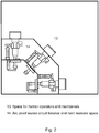
- Figs. 1-2 show examples of a switchgear or control gear for operation in a low voltage, medium voltage or high voltage substation.
- a three phase switchgear or control gear comprising at least one compartment 2, 11, 12, 13, 14, a plurality of components for a first phase, a plurality of components for a second phase, and a plurality of components for a third phase.
- the plurality of components for the first phase, the second phase and the third phase each comprise a connection to a main busbar 7, a circuit breaker actuator 1, a single phase circuit breaker pole 3, and a cable connection 6.
- the circuit breaker actuator and the single phase circuit breaker pole for the first phase are oriented along a first axis.
- the circuit breaker actuator and the single phase circuit breaker pole for the second phase are oriented along a second axis.
- the circuit breaker actuator and the single phase circuit breaker pole for the third phase are oriented along a third axis.
- the first axis the second axis and the third axis are inclined to each other.
- the plurality of components for the first phase the second phase and the third phase are housed in the at least one compartment. Referring to Fig. 1 it can be seen that the circuit breaker poles for the three phases point in different directions, and the axes referred to above extend through the centre of these, converging in compartment 12.
- the first axis is angled at 90 degrees to the third axis.
- the second axis is symmetrically oriented with respect to the first axis and with respect to the third axis.
- the second axis is angled at 45 degrees to the first axis.
- the second axis is angled at 45 degrees to the third axis.
- the first axis is horizontal
- the second axis is angled 45 degrees to the horizontal
- the third axis is vertical
- the at least one compartment comprises at least two compartments.
- the circuit breaker actuator, the single phase circuit breaker pole are housed in at least one first compartment 11, 13, 14 of the at least two compartments.
- the three cable connections are housed in a second compartment 12 of the at least two compartments.
- the first axis the second axis and the third axis converge toward the second compartment 12.
- the second compartment 12 comprises a door or removable wall section.
- the switchgear or control gear is configured such that an operator can gain access to the inside of the second compartment via the door or removable wall section whilst the switchgear or control gear is in operation.
- the second compartment 12 is separated from an adjacent compartment 11, 14 of the at least one first compartment by an arc proof segregation.
- rotation of the single phase circuit breaker pole for each phase is configured to function as a three position disconnector.
- rotation of the single phase circuit breaker pole for each phase is configured for connection, disconnection and earthing functions.
- the plurality of components for the first phase, the second phase and the third phase each comprise a pole rotation drive configured to rotate the corresponding single phase circuit breaker pole for each phase.
- the plurality of components for the first phase, the second phase and the third phase each comprise a linear or rotational three position disconnector switch and a drive for the disconnector switch.
- the plurality of components for the first phase, the second phase and the third phase each comprise a vacuum interrupter located in a central axis of the single phase circuit breaker pole along the first, second and third axis for the corresponding phases.
- the three vacuum interrupters are configured for current interruption.
- sets of bushings are used to connect the cable connections for each phase in the second compartment 12 to components for each phase housed in the at least one first compartment 11, 13, 14.
- current sensors 4 and voltage sensors 5 are embedded into each of the three sets of bushings.
- the at least one first compartment comprises two compartments.
- the three circuit breaker actuators are housed in a first compartment 13 of the two compartments.
- the three main busbars and three single phase circuit breaker poles are housed in a second compartment 14 of the two compartments.
- the first compartment 13 within which the three circuit breaker actuators are housed comprises a door or removable wall section.
- the switchgear or control gear is configured such that an operator can gain access to the inside of the first compartment 13 via the door or removable wall section whilst the switchgear or control gear is in operation.
- the second compartment 14 of the two compartments within which the three main busbars and the three single phase circuit breaker poles are housed is separated from the first compartment 13 of the two compartments within which the three circuit breaker actuators are housed by an arc proof segregation.
- current sensors 4 and voltage sensors 5 are embedded in each of the three single phase circuit breaker poles.
- current sensors 4 and voltage sensors 5 are standalone sensors.
- FIG. 1 shows a detailed example of a three phase switchgear or control gear, where for ease of reference the following features shown are listed:
- the arrangement of the non-parallel axes has one phase in a vertical direction, a second phase tilted at 45° from vertical and the third phase in a horizontal direction.
- All the phases meet in a common cable compartment, where a three core incoming or outgoing cable can then be easily terminated.
- the cable compartment is segregated from the main busbars and circuit breaker space by an arc proof segregation, and is a human operator accessible compartment of the switchgear or controlgear with unmanned operation.
- a cable compartment of one feeder is segregated from the cable compartments of other feeders by sidewalls, not shown for ease of visibility.
- a rotational circuit breaker pole can be used.
- the vacuum interrupter located in the central axis of the pole is used for current interruption, while rotation of the pole around the central axis serves for connection, disconnection and earthing as a three position disconnector switch.
- rotational pole 3 shown in Fig.1 can be replaced with a non-rotational pole in combination with a linear or rotational three position disconnector switch.
- the pole rotation drive in circuit breaker single phase actuator 1 is then replaced by a drive for the disconnector switch.
- the CB pole cartridge 3 protrudes from the circuit breaker and main busbar space 11 into the cable compartment 12.
- the CB pole cartridge can be located fully in the circuit breaker and main busbar space. Circuit transition to the cable compartment can then be provided by bushing allowing better sealing. This bushing can have embedded current 4 and voltage sensors 5, and these components then being integrated into the bushing instead of stand alone ones.
- the circuit breaker cartridge 3 shown in Fig.1 includes the circuit breaker pole, disconnector and the associated drives and auxiliaries.
- the cartridge can also include the current and voltage sensors.
- the switchgear and control gear of Fig.1 generally relates to switchgear or controlgear with unmanned operation.
- Fig.2 shows a detailed example utilizing the same principles as described with respect to Fig. 1 , but now for a human operated and maintained switchgear. This is achieved by adding an arc proof segregation covering the circuit breaker and main busbars space 14, thereby creating a human accessible space 13 for maintenance and operation personnel.
- the primary circuit can include other components and devices not described in Fig.1 , such as earthing switch, voltage indication, surge arrestors, Ultra Fast Earthing Switch (UFES), IS-limiters (as invented by ABB Calor Emag in 1955), contactors, load-break switches, fuses.
- Fig.1 earthing switch, voltage indication, surge arrestors, Ultra Fast Earthing Switch (UFES), IS-limiters (as invented by ABB Calor Emag in 1955), contactors, load-break switches, fuses.
Landscapes
- Engineering & Computer Science (AREA)
- Power Engineering (AREA)
- Gas-Insulated Switchgears (AREA)
- Patch Boards (AREA)
Priority Applications (3)
| Application Number | Priority Date | Filing Date | Title |
|---|---|---|---|
| EP18214196.0A EP3671990B1 (de) | 2018-12-19 | 2018-12-19 | Dreiphasiges schaltgerät |
| CN201911301788.9A CN111342384B (zh) | 2018-12-19 | 2019-12-17 | 三相开关装置或控制装置 |
| US16/718,242 US11005240B2 (en) | 2018-12-19 | 2019-12-18 | Three phase switchgear or control gear |
Applications Claiming Priority (1)
| Application Number | Priority Date | Filing Date | Title |
|---|---|---|---|
| EP18214196.0A EP3671990B1 (de) | 2018-12-19 | 2018-12-19 | Dreiphasiges schaltgerät |
Publications (2)
| Publication Number | Publication Date |
|---|---|
| EP3671990A1 true EP3671990A1 (de) | 2020-06-24 |
| EP3671990B1 EP3671990B1 (de) | 2021-11-24 |
Family
ID=64755141
Family Applications (1)
| Application Number | Title | Priority Date | Filing Date |
|---|---|---|---|
| EP18214196.0A Active EP3671990B1 (de) | 2018-12-19 | 2018-12-19 | Dreiphasiges schaltgerät |
Country Status (3)
| Country | Link |
|---|---|
| US (1) | US11005240B2 (de) |
| EP (1) | EP3671990B1 (de) |
| CN (1) | CN111342384B (de) |
Families Citing this family (4)
| Publication number | Priority date | Publication date | Assignee | Title |
|---|---|---|---|---|
| EP3671990B1 (de) * | 2018-12-19 | 2021-11-24 | ABB Schweiz AG | Dreiphasiges schaltgerät |
| EP3671988A1 (de) * | 2018-12-19 | 2020-06-24 | ABB Schweiz AG | Hermetischgasdichte schaltanlage mit einem einzelnes fach für leistungsschalter, trennschalter mit dreipositionen und hauptbusschiene. |
| EP3671989B1 (de) * | 2018-12-19 | 2025-08-13 | ABB Schweiz AG | Dreiphasen-schaltanlage mit einphasiger ausrüstung in einem gehäuse |
| EP4089698B1 (de) * | 2021-05-14 | 2025-01-22 | ABB Schweiz AG | Trennschalter mit drei positionen |
Citations (2)
| Publication number | Priority date | Publication date | Assignee | Title |
|---|---|---|---|---|
| DE19518126A1 (de) * | 1995-05-17 | 1996-11-21 | Josef F Perle | Leistungsschalter-Anlage |
| US20060138088A1 (en) * | 2003-06-02 | 2006-06-29 | Siemens Aktiengesellschaft | Disconnecting switch assembly |
Family Cites Families (14)
| Publication number | Priority date | Publication date | Assignee | Title |
|---|---|---|---|---|
| FR2620564B1 (fr) * | 1987-09-14 | 1989-12-01 | Merlin Gerin | Interrupteur de ligne multipolaire a isolement gazeux |
| JPH11146518A (ja) * | 1997-11-07 | 1999-05-28 | Toshiba Corp | ガス絶縁開閉装置 |
| DE19805705A1 (de) * | 1998-02-06 | 1999-08-12 | Asea Brown Boveri | Gasisolierte metallgekapselte Schaltanlage |
| DE10325681B3 (de) * | 2003-06-02 | 2004-10-21 | Siemens Ag | Schalteranordnung |
| DE102004061277A1 (de) * | 2004-12-13 | 2006-06-22 | Siemens Ag | Mehrphasiges Schaltgerät mit zumindest drei gleichartigen Unterbrechereinheiten |
| SE534914C2 (sv) * | 2010-06-18 | 2012-02-14 | Otto Electric Ltd | Ställverk med enfasisolering bestående av luftisolering och skärmar |
| JP5546697B1 (ja) * | 2013-08-22 | 2014-07-09 | 三菱電機株式会社 | ガス絶縁開閉装置 |
| CN105305288A (zh) * | 2015-10-29 | 2016-02-03 | 国网山东临朐县供电公司 | 具有分成封闭间隔的金属铠装配电装置 |
| CN106887360B (zh) * | 2017-04-27 | 2019-06-14 | 上海固缘电力科技有限公司 | 一种共箱式断路器 |
| EP3422502B1 (de) | 2017-06-28 | 2021-04-07 | ABB Schweiz AG | Unterstation für mittel- oder hochspannung mit schaltgerät oder steuergerät mit unbemannter operation und wartung |
| EP3422501B1 (de) | 2017-06-28 | 2021-04-28 | ABB Schweiz AG | Robot für unbemannten betrieb und wartung in einem mittel- oder hochspannungsgehäuse |
| EP3422503A1 (de) | 2017-06-28 | 2019-01-02 | ABB Schweiz AG | Ein interner roboter-manipulator für unbemannte betriebs- und wartungsarbeiten bei ausfahbarer leistungsschaltern und ein verfahren zum betreiben des roboter-manipulators |
| EP3421190B1 (de) | 2017-06-28 | 2022-05-04 | ABB Schweiz AG | Schaltgerät mit unbemannter bedienung und wartung sowie verfahren zum betrieb davon |
| EP3671990B1 (de) * | 2018-12-19 | 2021-11-24 | ABB Schweiz AG | Dreiphasiges schaltgerät |
-
2018
- 2018-12-19 EP EP18214196.0A patent/EP3671990B1/de active Active
-
2019
- 2019-12-17 CN CN201911301788.9A patent/CN111342384B/zh active Active
- 2019-12-18 US US16/718,242 patent/US11005240B2/en active Active
Patent Citations (2)
| Publication number | Priority date | Publication date | Assignee | Title |
|---|---|---|---|---|
| DE19518126A1 (de) * | 1995-05-17 | 1996-11-21 | Josef F Perle | Leistungsschalter-Anlage |
| US20060138088A1 (en) * | 2003-06-02 | 2006-06-29 | Siemens Aktiengesellschaft | Disconnecting switch assembly |
Non-Patent Citations (1)
| Title |
|---|
| ABB CALOR EMAG, ULTRA FAST EARTHING SWITCH (UFES), IS-LIMITERS, 1955 |
Also Published As
| Publication number | Publication date |
|---|---|
| US11005240B2 (en) | 2021-05-11 |
| CN111342384A (zh) | 2020-06-26 |
| EP3671990B1 (de) | 2021-11-24 |
| CN111342384B (zh) | 2021-10-29 |
| US20200203936A1 (en) | 2020-06-25 |
Similar Documents
| Publication | Publication Date | Title |
|---|---|---|
| EP1218995B1 (de) | Gasisolierte schaltanlage | |
| US11005240B2 (en) | Three phase switchgear or control gear | |
| JP4555857B2 (ja) | 真空絶縁スイッチギヤ | |
| EP2287874A2 (de) | Schaltanlage und Verfahren zum Betrieb einer Schaltanlage | |
| EP2474991B1 (de) | Schalteinheit und Schalthebel | |
| AU2011223278B2 (en) | A switch arrangement for an electrical switchgear | |
| CN113196602B (zh) | 在单个外壳中使用单相设备的三相开关设备 | |
| CN1977432B (zh) | 气体绝缘的中压开关设备 | |
| US11682885B2 (en) | Switchgear | |
| US11139642B2 (en) | Switchgear or control gear | |
| JP5183794B2 (ja) | スイッチギヤ | |
| CN103282991A (zh) | 一种开关设备和开关装置 | |
| CN113196603B (zh) | 三相开关机构或控制机构 | |
| JPH1189027A (ja) | スイッチギヤ | |
| EP4432324B1 (de) | Schaltanlagenarchitektur | |
| HK1129944B (en) | Vacuum insulated switchgear |
Legal Events
| Date | Code | Title | Description |
|---|---|---|---|
| PUAI | Public reference made under article 153(3) epc to a published international application that has entered the european phase |
Free format text: ORIGINAL CODE: 0009012 |
|
| STAA | Information on the status of an ep patent application or granted ep patent |
Free format text: STATUS: THE APPLICATION HAS BEEN PUBLISHED |
|
| AK | Designated contracting states |
Kind code of ref document: A1 Designated state(s): AL AT BE BG CH CY CZ DE DK EE ES FI FR GB GR HR HU IE IS IT LI LT LU LV MC MK MT NL NO PL PT RO RS SE SI SK SM TR |
|
| AX | Request for extension of the european patent |
Extension state: BA ME |
|
| STAA | Information on the status of an ep patent application or granted ep patent |
Free format text: STATUS: REQUEST FOR EXAMINATION WAS MADE |
|
| 17P | Request for examination filed |
Effective date: 20201209 |
|
| RBV | Designated contracting states (corrected) |
Designated state(s): AL AT BE BG CH CY CZ DE DK EE ES FI FR GB GR HR HU IE IS IT LI LT LU LV MC MK MT NL NO PL PT RO RS SE SI SK SM TR |
|
| GRAP | Despatch of communication of intention to grant a patent |
Free format text: ORIGINAL CODE: EPIDOSNIGR1 |
|
| STAA | Information on the status of an ep patent application or granted ep patent |
Free format text: STATUS: GRANT OF PATENT IS INTENDED |
|
| GRAJ | Information related to disapproval of communication of intention to grant by the applicant or resumption of examination proceedings by the epo deleted |
Free format text: ORIGINAL CODE: EPIDOSDIGR1 |
|
| STAA | Information on the status of an ep patent application or granted ep patent |
Free format text: STATUS: REQUEST FOR EXAMINATION WAS MADE |
|
| INTG | Intention to grant announced |
Effective date: 20210504 |
|
| GRAJ | Information related to disapproval of communication of intention to grant by the applicant or resumption of examination proceedings by the epo deleted |
Free format text: ORIGINAL CODE: EPIDOSDIGR1 |
|
| GRAP | Despatch of communication of intention to grant a patent |
Free format text: ORIGINAL CODE: EPIDOSNIGR1 |
|
| INTC | Intention to grant announced (deleted) | ||
| INTG | Intention to grant announced |
Effective date: 20210611 |
|
| GRAP | Despatch of communication of intention to grant a patent |
Free format text: ORIGINAL CODE: EPIDOSNIGR1 |
|
| STAA | Information on the status of an ep patent application or granted ep patent |
Free format text: STATUS: GRANT OF PATENT IS INTENDED |
|
| INTG | Intention to grant announced |
Effective date: 20210618 |
|
| INTC | Intention to grant announced (deleted) | ||
| INTG | Intention to grant announced |
Effective date: 20210713 |
|
| GRAS | Grant fee paid |
Free format text: ORIGINAL CODE: EPIDOSNIGR3 |
|
| GRAA | (expected) grant |
Free format text: ORIGINAL CODE: 0009210 |
|
| STAA | Information on the status of an ep patent application or granted ep patent |
Free format text: STATUS: THE PATENT HAS BEEN GRANTED |
|
| RAP3 | Party data changed (applicant data changed or rights of an application transferred) |
Owner name: ABB SCHWEIZ AG |
|
| AK | Designated contracting states |
Kind code of ref document: B1 Designated state(s): AL AT BE BG CH CY CZ DE DK EE ES FI FR GB GR HR HU IE IS IT LI LT LU LV MC MK MT NL NO PL PT RO RS SE SI SK SM TR |
|
| REG | Reference to a national code |
Ref country code: GB Ref legal event code: FG4D |
|
| REG | Reference to a national code |
Ref country code: AT Ref legal event code: REF Ref document number: 1450584 Country of ref document: AT Kind code of ref document: T Effective date: 20211215 |
|
| REG | Reference to a national code |
Ref country code: DE Ref legal event code: R096 Ref document number: 602018027089 Country of ref document: DE |
|
| REG | Reference to a national code |
Ref country code: IE Ref legal event code: FG4D |
|
| REG | Reference to a national code |
Ref country code: LT Ref legal event code: MG9D |
|
| REG | Reference to a national code |
Ref country code: NL Ref legal event code: MP Effective date: 20211124 |
|
| REG | Reference to a national code |
Ref country code: AT Ref legal event code: MK05 Ref document number: 1450584 Country of ref document: AT Kind code of ref document: T Effective date: 20211124 |
|
| PG25 | Lapsed in a contracting state [announced via postgrant information from national office to epo] |
Ref country code: RS Free format text: LAPSE BECAUSE OF FAILURE TO SUBMIT A TRANSLATION OF THE DESCRIPTION OR TO PAY THE FEE WITHIN THE PRESCRIBED TIME-LIMIT Effective date: 20211124 Ref country code: LT Free format text: LAPSE BECAUSE OF FAILURE TO SUBMIT A TRANSLATION OF THE DESCRIPTION OR TO PAY THE FEE WITHIN THE PRESCRIBED TIME-LIMIT Effective date: 20211124 Ref country code: FI Free format text: LAPSE BECAUSE OF FAILURE TO SUBMIT A TRANSLATION OF THE DESCRIPTION OR TO PAY THE FEE WITHIN THE PRESCRIBED TIME-LIMIT Effective date: 20211124 Ref country code: BG Free format text: LAPSE BECAUSE OF FAILURE TO SUBMIT A TRANSLATION OF THE DESCRIPTION OR TO PAY THE FEE WITHIN THE PRESCRIBED TIME-LIMIT Effective date: 20220224 Ref country code: AT Free format text: LAPSE BECAUSE OF FAILURE TO SUBMIT A TRANSLATION OF THE DESCRIPTION OR TO PAY THE FEE WITHIN THE PRESCRIBED TIME-LIMIT Effective date: 20211124 |
|
| PG25 | Lapsed in a contracting state [announced via postgrant information from national office to epo] |
Ref country code: IS Free format text: LAPSE BECAUSE OF FAILURE TO SUBMIT A TRANSLATION OF THE DESCRIPTION OR TO PAY THE FEE WITHIN THE PRESCRIBED TIME-LIMIT Effective date: 20220324 Ref country code: SE Free format text: LAPSE BECAUSE OF FAILURE TO SUBMIT A TRANSLATION OF THE DESCRIPTION OR TO PAY THE FEE WITHIN THE PRESCRIBED TIME-LIMIT Effective date: 20211124 Ref country code: PT Free format text: LAPSE BECAUSE OF FAILURE TO SUBMIT A TRANSLATION OF THE DESCRIPTION OR TO PAY THE FEE WITHIN THE PRESCRIBED TIME-LIMIT Effective date: 20220324 Ref country code: PL Free format text: LAPSE BECAUSE OF FAILURE TO SUBMIT A TRANSLATION OF THE DESCRIPTION OR TO PAY THE FEE WITHIN THE PRESCRIBED TIME-LIMIT Effective date: 20211124 Ref country code: NO Free format text: LAPSE BECAUSE OF FAILURE TO SUBMIT A TRANSLATION OF THE DESCRIPTION OR TO PAY THE FEE WITHIN THE PRESCRIBED TIME-LIMIT Effective date: 20220224 Ref country code: NL Free format text: LAPSE BECAUSE OF FAILURE TO SUBMIT A TRANSLATION OF THE DESCRIPTION OR TO PAY THE FEE WITHIN THE PRESCRIBED TIME-LIMIT Effective date: 20211124 Ref country code: LV Free format text: LAPSE BECAUSE OF FAILURE TO SUBMIT A TRANSLATION OF THE DESCRIPTION OR TO PAY THE FEE WITHIN THE PRESCRIBED TIME-LIMIT Effective date: 20211124 Ref country code: HR Free format text: LAPSE BECAUSE OF FAILURE TO SUBMIT A TRANSLATION OF THE DESCRIPTION OR TO PAY THE FEE WITHIN THE PRESCRIBED TIME-LIMIT Effective date: 20211124 Ref country code: GR Free format text: LAPSE BECAUSE OF FAILURE TO SUBMIT A TRANSLATION OF THE DESCRIPTION OR TO PAY THE FEE WITHIN THE PRESCRIBED TIME-LIMIT Effective date: 20220225 Ref country code: ES Free format text: LAPSE BECAUSE OF FAILURE TO SUBMIT A TRANSLATION OF THE DESCRIPTION OR TO PAY THE FEE WITHIN THE PRESCRIBED TIME-LIMIT Effective date: 20211124 |
|
| PG25 | Lapsed in a contracting state [announced via postgrant information from national office to epo] |
Ref country code: SM Free format text: LAPSE BECAUSE OF FAILURE TO SUBMIT A TRANSLATION OF THE DESCRIPTION OR TO PAY THE FEE WITHIN THE PRESCRIBED TIME-LIMIT Effective date: 20211124 Ref country code: SK Free format text: LAPSE BECAUSE OF FAILURE TO SUBMIT A TRANSLATION OF THE DESCRIPTION OR TO PAY THE FEE WITHIN THE PRESCRIBED TIME-LIMIT Effective date: 20211124 Ref country code: RO Free format text: LAPSE BECAUSE OF FAILURE TO SUBMIT A TRANSLATION OF THE DESCRIPTION OR TO PAY THE FEE WITHIN THE PRESCRIBED TIME-LIMIT Effective date: 20211124 Ref country code: EE Free format text: LAPSE BECAUSE OF FAILURE TO SUBMIT A TRANSLATION OF THE DESCRIPTION OR TO PAY THE FEE WITHIN THE PRESCRIBED TIME-LIMIT Effective date: 20211124 Ref country code: DK Free format text: LAPSE BECAUSE OF FAILURE TO SUBMIT A TRANSLATION OF THE DESCRIPTION OR TO PAY THE FEE WITHIN THE PRESCRIBED TIME-LIMIT Effective date: 20211124 Ref country code: CZ Free format text: LAPSE BECAUSE OF FAILURE TO SUBMIT A TRANSLATION OF THE DESCRIPTION OR TO PAY THE FEE WITHIN THE PRESCRIBED TIME-LIMIT Effective date: 20211124 |
|
| REG | Reference to a national code |
Ref country code: CH Ref legal event code: PL |
|
| REG | Reference to a national code |
Ref country code: DE Ref legal event code: R097 Ref document number: 602018027089 Country of ref document: DE |
|
| PG25 | Lapsed in a contracting state [announced via postgrant information from national office to epo] |
Ref country code: MC Free format text: LAPSE BECAUSE OF FAILURE TO SUBMIT A TRANSLATION OF THE DESCRIPTION OR TO PAY THE FEE WITHIN THE PRESCRIBED TIME-LIMIT Effective date: 20211124 |
|
| REG | Reference to a national code |
Ref country code: BE Ref legal event code: MM Effective date: 20211231 |
|
| PLBE | No opposition filed within time limit |
Free format text: ORIGINAL CODE: 0009261 |
|
| STAA | Information on the status of an ep patent application or granted ep patent |
Free format text: STATUS: NO OPPOSITION FILED WITHIN TIME LIMIT |
|
| PG25 | Lapsed in a contracting state [announced via postgrant information from national office to epo] |
Ref country code: LU Free format text: LAPSE BECAUSE OF NON-PAYMENT OF DUE FEES Effective date: 20211219 Ref country code: IE Free format text: LAPSE BECAUSE OF NON-PAYMENT OF DUE FEES Effective date: 20211219 Ref country code: AL Free format text: LAPSE BECAUSE OF FAILURE TO SUBMIT A TRANSLATION OF THE DESCRIPTION OR TO PAY THE FEE WITHIN THE PRESCRIBED TIME-LIMIT Effective date: 20211124 |
|
| 26N | No opposition filed |
Effective date: 20220825 |
|
| PG25 | Lapsed in a contracting state [announced via postgrant information from national office to epo] |
Ref country code: SI Free format text: LAPSE BECAUSE OF FAILURE TO SUBMIT A TRANSLATION OF THE DESCRIPTION OR TO PAY THE FEE WITHIN THE PRESCRIBED TIME-LIMIT Effective date: 20211124 Ref country code: BE Free format text: LAPSE BECAUSE OF NON-PAYMENT OF DUE FEES Effective date: 20211231 |
|
| PG25 | Lapsed in a contracting state [announced via postgrant information from national office to epo] |
Ref country code: LI Free format text: LAPSE BECAUSE OF NON-PAYMENT OF DUE FEES Effective date: 20211231 Ref country code: CH Free format text: LAPSE BECAUSE OF NON-PAYMENT OF DUE FEES Effective date: 20211231 |
|
| PG25 | Lapsed in a contracting state [announced via postgrant information from national office to epo] |
Ref country code: IT Free format text: LAPSE BECAUSE OF FAILURE TO SUBMIT A TRANSLATION OF THE DESCRIPTION OR TO PAY THE FEE WITHIN THE PRESCRIBED TIME-LIMIT Effective date: 20211124 |
|
| PG25 | Lapsed in a contracting state [announced via postgrant information from national office to epo] |
Ref country code: CY Free format text: LAPSE BECAUSE OF FAILURE TO SUBMIT A TRANSLATION OF THE DESCRIPTION OR TO PAY THE FEE WITHIN THE PRESCRIBED TIME-LIMIT Effective date: 20211124 |
|
| PG25 | Lapsed in a contracting state [announced via postgrant information from national office to epo] |
Ref country code: HU Free format text: LAPSE BECAUSE OF FAILURE TO SUBMIT A TRANSLATION OF THE DESCRIPTION OR TO PAY THE FEE WITHIN THE PRESCRIBED TIME-LIMIT; INVALID AB INITIO Effective date: 20181219 |
|
| GBPC | Gb: european patent ceased through non-payment of renewal fee |
Effective date: 20221219 |
|
| PG25 | Lapsed in a contracting state [announced via postgrant information from national office to epo] |
Ref country code: GB Free format text: LAPSE BECAUSE OF NON-PAYMENT OF DUE FEES Effective date: 20221219 |
|
| PG25 | Lapsed in a contracting state [announced via postgrant information from national office to epo] |
Ref country code: MK Free format text: LAPSE BECAUSE OF FAILURE TO SUBMIT A TRANSLATION OF THE DESCRIPTION OR TO PAY THE FEE WITHIN THE PRESCRIBED TIME-LIMIT Effective date: 20211124 |
|
| PG25 | Lapsed in a contracting state [announced via postgrant information from national office to epo] |
Ref country code: MT Free format text: LAPSE BECAUSE OF FAILURE TO SUBMIT A TRANSLATION OF THE DESCRIPTION OR TO PAY THE FEE WITHIN THE PRESCRIBED TIME-LIMIT Effective date: 20211124 |
|
| PG25 | Lapsed in a contracting state [announced via postgrant information from national office to epo] |
Ref country code: TR Free format text: LAPSE BECAUSE OF FAILURE TO SUBMIT A TRANSLATION OF THE DESCRIPTION OR TO PAY THE FEE WITHIN THE PRESCRIBED TIME-LIMIT Effective date: 20211124 |
|
| PGFP | Annual fee paid to national office [announced via postgrant information from national office to epo] |
Ref country code: DE Payment date: 20251211 Year of fee payment: 8 |
|
| PGFP | Annual fee paid to national office [announced via postgrant information from national office to epo] |
Ref country code: FR Payment date: 20251229 Year of fee payment: 8 |