EP4089698B1 - Trennschalter mit drei positionen - Google Patents
Trennschalter mit drei positionen Download PDFInfo
- Publication number
- EP4089698B1 EP4089698B1 EP21173953.7A EP21173953A EP4089698B1 EP 4089698 B1 EP4089698 B1 EP 4089698B1 EP 21173953 A EP21173953 A EP 21173953A EP 4089698 B1 EP4089698 B1 EP 4089698B1
- Authority
- EP
- European Patent Office
- Prior art keywords
- contact
- power out
- out contact
- switch
- position disconnector
- Prior art date
- Legal status (The legal status is an assumption and is not a legal conclusion. Google has not performed a legal analysis and makes no representation as to the accuracy of the status listed.)
- Active
Links
Images
Classifications
-
- H—ELECTRICITY
- H01—ELECTRIC ELEMENTS
- H01H—ELECTRIC SWITCHES; RELAYS; SELECTORS; EMERGENCY PROTECTIVE DEVICES
- H01H31/00—Air-break switches for high tension without arc-extinguishing or arc-preventing means
- H01H31/02—Details
- H01H31/04—Interlocking mechanisms
- H01H31/08—Interlocking mechanisms for interlocking two or more parts of the mechanism for operating contacts
-
- H—ELECTRICITY
- H01—ELECTRIC ELEMENTS
- H01H—ELECTRIC SWITCHES; RELAYS; SELECTORS; EMERGENCY PROTECTIVE DEVICES
- H01H1/00—Contacts
- H01H1/12—Contacts characterised by the manner in which co-operating contacts engage
- H01H1/36—Contacts characterised by the manner in which co-operating contacts engage by sliding
- H01H1/365—Bridging contacts
-
- H—ELECTRICITY
- H01—ELECTRIC ELEMENTS
- H01H—ELECTRIC SWITCHES; RELAYS; SELECTORS; EMERGENCY PROTECTIVE DEVICES
- H01H1/00—Contacts
- H01H1/06—Contacts characterised by the shape or structure of the contact-making surface, e.g. grooved
-
- H—ELECTRICITY
- H01—ELECTRIC ELEMENTS
- H01H—ELECTRIC SWITCHES; RELAYS; SELECTORS; EMERGENCY PROTECTIVE DEVICES
- H01H1/00—Contacts
- H01H1/12—Contacts characterised by the manner in which co-operating contacts engage
- H01H1/14—Contacts characterised by the manner in which co-operating contacts engage by abutting
- H01H1/20—Bridging contacts
-
- H—ELECTRICITY
- H01—ELECTRIC ELEMENTS
- H01H—ELECTRIC SWITCHES; RELAYS; SELECTORS; EMERGENCY PROTECTIVE DEVICES
- H01H1/00—Contacts
- H01H1/62—Heating or cooling of contacts
-
- H—ELECTRICITY
- H01—ELECTRIC ELEMENTS
- H01H—ELECTRIC SWITCHES; RELAYS; SELECTORS; EMERGENCY PROTECTIVE DEVICES
- H01H31/00—Air-break switches for high tension without arc-extinguishing or arc-preventing means
- H01H31/02—Details
- H01H31/04—Interlocking mechanisms
-
- H—ELECTRICITY
- H01—ELECTRIC ELEMENTS
- H01H—ELECTRIC SWITCHES; RELAYS; SELECTORS; EMERGENCY PROTECTIVE DEVICES
- H01H31/00—Air-break switches for high tension without arc-extinguishing or arc-preventing means
- H01H31/26—Air-break switches for high tension without arc-extinguishing or arc-preventing means with movable contact that remains electrically connected to one line in open position of switch
- H01H31/32—Air-break switches for high tension without arc-extinguishing or arc-preventing means with movable contact that remains electrically connected to one line in open position of switch with rectilinearly-movable contact
-
- H—ELECTRICITY
- H01—ELECTRIC ELEMENTS
- H01H—ELECTRIC SWITCHES; RELAYS; SELECTORS; EMERGENCY PROTECTIVE DEVICES
- H01H1/00—Contacts
- H01H1/12—Contacts characterised by the manner in which co-operating contacts engage
- H01H1/36—Contacts characterised by the manner in which co-operating contacts engage by sliding
Definitions
- the present invention relates to three-position disconnector switch and a switchgear or control gear for low voltage, medium voltage or high voltage use with a substation.
- a disconnector for example in an air insulated medium voltage switchgear, requires that there are three switch positions, each with full dielectric performance. Any design of a disconnector must respect sufficient dielectric distances to achieve a middle position that is fully insulated. These distances are repeated three times with a linear variant of a disconnector, where a length of the disconnector is influenced twice by the air gap and also by a length of a movable contact which must be long enough to make contact between contacts within the constraints of also having extended air gaps.
- EP3671789A1 relates to a medium or high voltage switchgear with a three position switch.
- the three position switch comprises a tube shaped conductor for connection of a cable and the three position switch comprises an earthing contact.
- the earthing contact is arranged inside of and coaxial to the tube shaped conductor.
- EP3754681A1 relates to a three-position disconnector switch, comprising: an earthing contact, a power out contact, a power in contact, a piston, and a threaded rod.
- a length of the piston is such that in a first switch position an outer surface of a wall of the piston makes an electrical contact between the power out contact and the power in contact.
- the length of the piston is such that in a second switch position the outer surface of the wall of the piston does not make an electrical contact with either the earthing contact or the power in contact.
- the length of the piston is such that in a third switch position the outer surface of wall of the piston makes an electrical contact between the earthing contact and the power out contact.
- the piston comprises an inner threaded section configured to engage with the threaded rod, wherein a length of the inner threaded section is less than the length of the piston. Rotation of the threaded rod is configured to engage with the inner threaded section to move the switch between the different switch positions.
- a three-position disconnector switch comprising:
- the power out contact comprises a first part and a second part, and the first part is connected to the second part by a leg portion.
- a first switch position an outer surface of a wall of the piston makes a direct electrical contact with the first part of the power out contact and makes a direct electrical contact with the power in contact.
- the outer surface of the wall of the piston makes a direct electrical contact with the first part of the power out contact and makes a direct electrical contact with the second part of the power out contact.
- the outer surface of wall of the piston makes a direct electrical contact with the second part of the power out contact and makes a direct electrical contact with the earthing contact.
- the piston is configured to move along an axis of the three-position disconnector switch to transition the three-position disconnector switch between the different switch positions.
- the outer surface of the wall of the piston does not makes a direct electrical contact with the second part of the power out contact.
- the outer surface of the wall of the piston does not makes a direct electrical contact with the first part of the power out contact.
- an outer extent of the first part of the power out contact faces the power in contact and an outer extent of the second part of the power out contact faces the earthing contact.
- a length of the piston in the direction of the axis of the three-position disconnector switch is less that or equal to a distance between the outer extent of the first part of the power out contact and the outer extent of the second part of the power out contact.
- a mass of material of the first part of the power out contact is greater than a mass of material of the second part of the power out contact.
- the first part of the power out contact comprises an annular portion centred around the axis of the three-position disconnector switch.
- the annular portion comprises at least one cooling hole extending through a wall of the annular portion.
- the second part of the power out contact comprises an annular portion centred around the axis of the three-position disconnector switch.
- the annular portion comprises at least one cooling hole extending through a wall of the annular portion.
- the annular portion comprises an open cooling channel in the wall of the annular portion, and wherein the open cooling channel is centred around the axis of the three-position disconnector switch.
- the leg portion of the power out contact comprises at least one cooling hole.
- the at least one cooling hole of the leg portion of the power out contact is located within a part of the leg portion of the power out contact between a mounting region of the leg portion of the power out contact and the second part of the power out contact.
- a low voltage, medium voltage or high voltage switchgear or control gear comprising one or more three-position disconnector switches according to the first aspect.
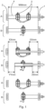
- Figs. 1-3 relate to a new three-position disconnector switch, where the new three-position disconnector switch is shown at the top of Fig. 1 in contrast to an exisiting three-position disconnector switch that is shown at the bottom in Fig. 1 .
- the new three-position disconnector switch comprises an earthing contact 1, a power out contact 2, a power in contact 3, and a piston (4).
- the power out contact comprises a first part 2a and a second part 2b.
- the first part 2a is connected to the second part 2b by a leg portion 2c.
- a first switch position an outer surface of a wall of the piston makes a direct electrical contact with the first part of the power out contact and makes a direct electrical contact with the power in contact.
- the outer surface of the wall of the piston makes a direct electrical contact with the first part of the power out contact and makes a direct electrical contact with the second part of the power out contact.
- the outer surface of wall of the piston makes a direct electrical contact with the second part of the power out contact and makes a direct electrical contact with the earthing contact.
- the piston is configured to move along an axis of the three-position disconnector switch to transition the three-position disconnector switch between the different switch positions.
- the outer surface of the wall of the piston does not makes a direct electrical contact with the second part of the power out contact.
- the outer surface of the wall of the piston does not makes a direct electrical contact with the first part of the power out contact.
- an outer extent of the first part of the power out contact faces the power in contact and an outer extent of the second part of the power out contact faces the earthing contact.
- a length of the piston in the direction of the axis of the three-position disconnector switch is less that or equal to a distance between the outer extent of the first part of the power out contact and the outer extent of the second part of the power out contact.
- a mass of material of the first part of the power out contact is greater than a mass of material of the second part of the power out contact.
- the first part of the power out contact comprises an annular portion centred around the axis of the three-position disconnector switch.
- the annular portion comprises at least one cooling hole 5 extending through a wall of the annular portion.
- the second part of the power out contact comprises an annular portion centred around the axis of the three-position disconnector switch.
- the annular portion comprises at least one cooling hole 6 extending through a wall of the annular portion.
- the annular portion comprises an open cooling channel 8 in the wall of the annular portion, and wherein the open cooling channel is centred around the axis of the three-position disconnector switch.
- the leg portion of the power out contact comprises at least one cooling hole 7.
- the at least one cooling hole of the leg portion of the power out contact is located within a part of the leg portion of the power out contact between a mounting region of the leg portion of the power out contact and the second part of the power out contact.
- the new three-position disconnector switch can be utilized in a low voltage, medium voltage or high voltage switchgear or control gear, and where there can be for example three such disconnectors, one for each phase of a three phase system.
- the inventors realised that a way to shorten traditional linear three-position disconnector swiotches was to change a single middle contact (power out contact) to double middle contact (power out contact).
- the new design is to change a single middle contact, here the power out contact, to double middle contact, or power out contact 2.
- This configuration allows to have longer air gaps in the same overall dimensions of the disconnector therefore to reach higher dielectric limits without suffering on cost and size of the solution.
- Fig. 1 shows at "A" a new three-position disconnector switch and at "B" an exisiting three-position disconnector switch.
- the new three-position disconnector switch has a fork type double middle or power out contact 2. Shown at the left, in a first switch position the piston 4 contacts the power in contact and a first part 2a of the middle or power out contact 2. Shown in the middle, in a second switch position the piston contacts both the first part 2a and a second part 2b of the middle or power out contact 2. In a third switch position the poston 4 contacts the right hand side or second part 2b of the middle or power out contact and contacts an earthing contact 1.
- Another advantage of the new design with a fork type middle or power out contact 2 is that in the middle position, from a dielectric point of view, the piston 4 can "hide” inside the middle or power out contact. This shape of the middle contact can provide for enhanced dielectric protection.
- the fork type middle or power out contact 2 also leads to cooling and cost benefits.
- the piston 4 In addition to its naturally greater surface for convection and radiation from having two parts, when the three-posiiton disconnector switch is in a first switch position where the piston connects the power in contact 3 to the middle or power out contact 2, the piston 4 only connects to a first part 2a of the power out connector.
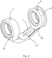
- the power out connector 2 has a leg portion 2c that connects the first part 2a to the second part 2b. As shown in fig. 2 the leg portion 2c has mounting holes in a flat portion that connects to the power out line.
- the current flows through first part 2a of the contact and part of the leg portion only and does not flow through the second part 2b.
- the second part 2b of the contact 2 can be light-weight due to its requiirment to carry a short-circuit current for a short period of time only. This results in a lower production cost than for a contact 2 that has equally robust halves. Also, the contact can have free space directly between side contacts themselves. Side contacts are materially connected with middle contact area in a shortest and cost-effective way.
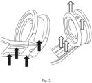
- cooling holes/channel/gaps in the second part 2b of the contact 2 can act as a cooler to further increase system performance when normally operated.
- the shape is demonstrated at Fig. 3 , where cold air is shown at the left that is heated up and is flows around and through cooling holes/channel 6, 7 and 8 and is heated up and flows away from the part shown at the right and therefore provides for cooling.
- cooling air gaps 7 in the leg 2c of the second part of the power out contact 2 that has a ring or annular shape and there can also be a channel 8 around the ring for additional ventilation.
- cooling holes 5 and 6 can be provided in the annular or ring shapes of the first part 2a and second part of the power out contact, to allow air to flow through and provide cooling.
Landscapes
- Gas-Insulated Switchgears (AREA)
Claims (13)
- Dreistellungs-Trennschalter, umfassend:einen Erdungskontakt (1);einen Ausgangskontakt (2);einen Eingangskontakt (3); undeinen Kolben (4);wobei der Ausgangskontakt einen ersten Teil (2a) und einen zweiten Teil (2b) umfasst, und wobei der erste Teil mit dem zweiten Teil durch einen Schenkelsabschnitt (2c) verbunden ist;wobei in einer ersten Schalterstellung eine äußere Oberfläche einer Wand des Kolbens direkten elektrischen Kontakt mit dem ersten Teil des Ausgangskontakts und direkten elektrischen Kontakt mit dem Eingangskontakt herstellt;wobei in einer zweiten Schalterstellung die äußere Oberfläche der Wand des Kolbens direkten elektrischen Kontakt mit dem ersten Teil des Ausgangskontakts und direkten elektrischen Kontakt mit dem zweiten Teil des Ausgangskontakts herstellt;wobei in einer dritten Schalterstellung die äußere Oberfläche der Wand des Kolbens direkten elektrischen Kontakt mit dem zweiten Teil des Ausgangskontakts und direkten elektrischen Kontakt mit dem Erdungskontakt herstellt; undwobei der Kolben so eingerichtet ist, sich entlang einer Achse des Dreistellungs-Trennschalter zu bewegen, um den Dreistellungs-Trennschalter zwischen den verschiedenen Schalterstellungen zu überführen.
- Dreistellungs-Trennschalter nach Anspruch 1, wobei in der ersten Schalterstellung die äußere Oberfläche der Wand des Kolbens keinen direkten elektrischen Kontakt mit dem zweiten Teil des Ausgangskontakts herstellt.
- Dreistellungs-Trennschalter nach einem der Ansprüche 1-2, wobei in der dritten Schalterstellung die äußere Oberfläche der Wand des Kolbens keinen direkten elektrischen Kontakt mit dem ersten Teil des Ausgangskontakts herstellt.
- Dreistellungs-Trennschalter nach einem der Ansprüche 1-3, wobei ein äußerer Bereich des ersten Teils des Ausgangskontakts dem Eingangskontakt zugewandt ist und ein äußerer Bereich des zweiten Teils des Ausgangskontakts dem Erdungskontakt zugewandt ist, und wobei eine Länge des Kolbens in Richtung der Achse des Dreistellungs-Trennschalter kleiner oder gleich einem Abstand zwischen dem äußeren Bereich des ersten Teils des Ausgangskontakts und dem äußeren Bereich des zweiten Teils des Ausgangskontakts ist.
- Dreistellungs-Trennschalter nach einem der Ansprüche 1-4, wobei die Masse des Materials des ersten Teils des Ausgangskontakts größer ist als die Masse des Materials des zweiten Teils des Ausgangskontakts.
- Dreistellungs-Trennschalter nach einem der Ansprüche 1-5, wobei der erste Teil des Ausgangskontakts einen ringförmigen Abschnitt umfasst, der um die Achse des Dreistellungs-Trennschalter zentriert ist.
- Dreistellungs-Trennschalter nach Anspruch 6, wobei der ringförmige Abschnitt mindestens ein Kühlloch (5) umfasst, das durch eine Wand des ringförmigen Abschnitts verläuft.
- Dreistellungs-Trennschalter nach einem der Ansprüche 1-7, wobei der zweite Teil des Ausgangskontakts einen ringförmigen Abschnitt umfasst, der um die Achse des Dreistellungs-Trennschalter zentriert ist.
- Dreistellungs-Trennschalter nach Anspruch 8, wobei der ringförmige Abschnitt mindestens ein Kühlloch (6) umfasst, das durch eine Wand des ringförmigen Abschnitts verläuft.
- Dreistellungs-Trennschalter nach einem der Ansprüche 8-9, wobei der ringförmige Abschnitt einen offenen Kühlkanal (8) in der Wand des ringförmigen Abschnitts umfasst, und wobei der offene Kühlkanal um die Achse des Dreistellungs-Trennschalter zentriert ist.
- Dreistellungs-Trennschalter nach einem der Ansprüche 1-10, wobei der Schenkelsabschnitt des Ausgangskontakts mindestens ein Kühlloch (7) umfasst.
- Dreistellungs-Trennschalter nach Anspruch 10, wobei sich das mindestens eine Kühlloch des Schenkelsabschnitts des Ausgangskontakts in einem Bereich des Schenkelsabschnitts zwischen einem Befestigungsbereich des Schenkelsabschnitts des Ausgangskontakts und dem zweiten Teil des Ausgangskontakts befindet.
- Ein Nieder-, Mittel- oder Hochspannungs-Schaltgerät oder Steuergerät, das einen oder mehrere Dreistellungs-Trennschalter nach einem der Ansprüche 1-12 umfasst.
Priority Applications (3)
| Application Number | Priority Date | Filing Date | Title |
|---|---|---|---|
| EP21173953.7A EP4089698B1 (de) | 2021-05-14 | 2021-05-14 | Trennschalter mit drei positionen |
| US17/741,569 US11791109B2 (en) | 2021-05-14 | 2022-05-11 | Three-position disconnector switch |
| CN202210517518.7A CN115346826A (zh) | 2021-05-14 | 2022-05-12 | 三位隔离开关 |
Applications Claiming Priority (1)
| Application Number | Priority Date | Filing Date | Title |
|---|---|---|---|
| EP21173953.7A EP4089698B1 (de) | 2021-05-14 | 2021-05-14 | Trennschalter mit drei positionen |
Publications (2)
| Publication Number | Publication Date |
|---|---|
| EP4089698A1 EP4089698A1 (de) | 2022-11-16 |
| EP4089698B1 true EP4089698B1 (de) | 2025-01-22 |
Family
ID=75936793
Family Applications (1)
| Application Number | Title | Priority Date | Filing Date |
|---|---|---|---|
| EP21173953.7A Active EP4089698B1 (de) | 2021-05-14 | 2021-05-14 | Trennschalter mit drei positionen |
Country Status (3)
| Country | Link |
|---|---|
| US (1) | US11791109B2 (de) |
| EP (1) | EP4089698B1 (de) |
| CN (1) | CN115346826A (de) |
Family Cites Families (18)
| Publication number | Priority date | Publication date | Assignee | Title |
|---|---|---|---|---|
| DE2033853B2 (de) * | 1970-06-30 | 1975-10-30 | Siemens Ag, 1000 Berlin Und 8000 Muenchen | Blaskolbenschalter für Hochspannung |
| SE406673B (sv) * | 1977-07-08 | 1979-02-19 | Asea Ab | Jordningsomkopplare for gasisolerade, metallkapslade hogspenningsstellverk |
| JP4230739B2 (ja) * | 2002-08-29 | 2009-02-25 | 三菱電機株式会社 | ガス絶縁開閉装置 |
| AU2005253220B2 (en) * | 2004-06-09 | 2008-10-23 | Abb Technology Ag | Gas-Insulated Switchgear Assembly |
| JP5471925B2 (ja) * | 2010-07-16 | 2014-04-16 | 株式会社日立製作所 | 接地開閉器付断路器 |
| CN102280297B (zh) * | 2011-07-19 | 2013-08-07 | 沈阳华利能源设备制造有限公司 | 一种三工位隔离开关 |
| US8729985B2 (en) * | 2012-01-23 | 2014-05-20 | Electro-Mechanical Corporation | Switchgear visible disconnect mechanical interlock |
| PL2645395T3 (pl) * | 2012-03-26 | 2015-05-29 | Abb Schweiz Ag | Elektryczne urządzenie przełączające i związane z nim urządzenie elektryczne |
| CN203553024U (zh) * | 2013-09-27 | 2014-04-16 | 北京电研华源电力技术有限公司 | 一种三工位隔离开关固封极柱 |
| CN205050751U (zh) * | 2015-09-06 | 2016-02-24 | 天津平高智能电气有限公司 | 一种动触头及直动式隔离开关 |
| CN207124152U (zh) * | 2017-09-05 | 2018-03-20 | 宁波耐森电气科技有限公司 | 一种隔离开关触头装置 |
| CN108010789A (zh) * | 2017-12-13 | 2018-05-08 | 上海天灵开关厂有限公司 | 一种带有散热结构的大电流直动式三工位开关 |
| CN207587609U (zh) * | 2017-12-28 | 2018-07-06 | 宁波耐森电气科技有限公司 | 一种直动式三工位隔离开关 |
| EP3671990B1 (de) * | 2018-12-19 | 2021-11-24 | ABB Schweiz AG | Dreiphasiges schaltgerät |
| EP3671789B1 (de) * | 2018-12-21 | 2021-06-23 | ABB Schweiz AG | Mittel- oder hochspannungsschaltgerät mit dreistellungsschalter |
| CN209591897U (zh) * | 2019-03-28 | 2019-11-05 | 南瑞集团有限公司 | 一种充气柜用直动式三工位开关 |
| EP3754681A1 (de) * | 2019-06-21 | 2020-12-23 | ABB Schweiz AG | Trennschalter mit drei positionen |
| EP3836182B1 (de) * | 2019-12-11 | 2023-03-08 | ABB Schweiz AG | Trennschalter mit drei positionen |
-
2021
- 2021-05-14 EP EP21173953.7A patent/EP4089698B1/de active Active
-
2022
- 2022-05-11 US US17/741,569 patent/US11791109B2/en active Active
- 2022-05-12 CN CN202210517518.7A patent/CN115346826A/zh active Pending
Also Published As
| Publication number | Publication date |
|---|---|
| EP4089698A1 (de) | 2022-11-16 |
| US20220367127A1 (en) | 2022-11-17 |
| CN115346826A (zh) | 2022-11-15 |
| US11791109B2 (en) | 2023-10-17 |
Similar Documents
| Publication | Publication Date | Title |
|---|---|---|
| EP2077569B1 (de) | Vakuumschaltgetriebe | |
| JP2015023685A (ja) | スイッチギヤ | |
| EP3008740B1 (de) | Hochstromvakuumschalter mit sektionaler elektrode und mehrfachen wärmerohren | |
| US20220216021A1 (en) | Circuit breaker | |
| EP2819143A1 (de) | Tank-Typ-Vakuumschalter | |
| US6462295B1 (en) | High-voltage power circuit breaker comprising an insulating nozzle | |
| CN113966541A (zh) | 三位置隔离开关 | |
| EP4089698B1 (de) | Trennschalter mit drei positionen | |
| CN113228217B (zh) | 中压开关极 | |
| US20070151953A1 (en) | Compressed-gas insulation switching device | |
| WO2013189782A1 (en) | Disk-shaped insulator for gas-insulated switchgear | |
| US10763062B2 (en) | Switching device with dual conductive housing | |
| CN216818194U (zh) | 一种断路器结构 | |
| US7982143B2 (en) | Electric switch having an annular stationary contact | |
| EP3093866B1 (de) | Elektrische poleinheit für gasisolierte mittelspannungs-schutzschalter | |
| DK1872380T3 (en) | LOAD DISTRIBUTOR AND SWITCH UNIT WITH LOAD DETAILS | |
| JP6471253B2 (ja) | タンク形真空遮断器 | |
| CN105378873A (zh) | 用于可调式变压器的有载选择器和用于有载选择器的预选择器的承载臂 | |
| KR200488177Y1 (ko) | 가스절연개폐장치의 접지스위치 | |
| CN104037012A (zh) | 一种具有插入式接地工位的三工位真空灭弧室 | |
| EP3893261B1 (de) | Polkontaktarm für eine elektrische poleinheit | |
| US12368287B2 (en) | Adaptation module for a gas-insulated switchgear | |
| EP4224650B1 (de) | Anpassungsmodul für eine gasisolierte schaltanlage | |
| RU2642838C2 (ru) | Высоковольтный контактный узел вакуумного выключателя и разъединителя | |
| JP6374147B2 (ja) | タンク形真空遮断器 |
Legal Events
| Date | Code | Title | Description |
|---|---|---|---|
| PUAI | Public reference made under article 153(3) epc to a published international application that has entered the european phase |
Free format text: ORIGINAL CODE: 0009012 |
|
| STAA | Information on the status of an ep patent application or granted ep patent |
Free format text: STATUS: THE APPLICATION HAS BEEN PUBLISHED |
|
| AK | Designated contracting states |
Kind code of ref document: A1 Designated state(s): AL AT BE BG CH CY CZ DE DK EE ES FI FR GB GR HR HU IE IS IT LI LT LU LV MC MK MT NL NO PL PT RO RS SE SI SK SM TR |
|
| STAA | Information on the status of an ep patent application or granted ep patent |
Free format text: STATUS: REQUEST FOR EXAMINATION WAS MADE |
|
| 17P | Request for examination filed |
Effective date: 20230426 |
|
| RBV | Designated contracting states (corrected) |
Designated state(s): AL AT BE BG CH CY CZ DE DK EE ES FI FR GB GR HR HU IE IS IT LI LT LU LV MC MK MT NL NO PL PT RO RS SE SI SK SM TR |
|
| GRAP | Despatch of communication of intention to grant a patent |
Free format text: ORIGINAL CODE: EPIDOSNIGR1 |
|
| STAA | Information on the status of an ep patent application or granted ep patent |
Free format text: STATUS: GRANT OF PATENT IS INTENDED |
|
| INTG | Intention to grant announced |
Effective date: 20240924 |
|
| GRAS | Grant fee paid |
Free format text: ORIGINAL CODE: EPIDOSNIGR3 |
|
| GRAA | (expected) grant |
Free format text: ORIGINAL CODE: 0009210 |
|
| STAA | Information on the status of an ep patent application or granted ep patent |
Free format text: STATUS: THE PATENT HAS BEEN GRANTED |
|
| AK | Designated contracting states |
Kind code of ref document: B1 Designated state(s): AL AT BE BG CH CY CZ DE DK EE ES FI FR GB GR HR HU IE IS IT LI LT LU LV MC MK MT NL NO PL PT RO RS SE SI SK SM TR |
|
| REG | Reference to a national code |
Ref country code: GB Ref legal event code: FG4D |
|
| REG | Reference to a national code |
Ref country code: CH Ref legal event code: EP |
|
| REG | Reference to a national code |
Ref country code: IE Ref legal event code: FG4D |
|
| REG | Reference to a national code |
Ref country code: DE Ref legal event code: R096 Ref document number: 602021025060 Country of ref document: DE |
|
| REG | Reference to a national code |
Ref country code: NL Ref legal event code: MP Effective date: 20250122 |
|
| PG25 | Lapsed in a contracting state [announced via postgrant information from national office to epo] |
Ref country code: NL Free format text: LAPSE BECAUSE OF FAILURE TO SUBMIT A TRANSLATION OF THE DESCRIPTION OR TO PAY THE FEE WITHIN THE PRESCRIBED TIME-LIMIT Effective date: 20250122 |
|
| PG25 | Lapsed in a contracting state [announced via postgrant information from national office to epo] |
Ref country code: RS Free format text: LAPSE BECAUSE OF FAILURE TO SUBMIT A TRANSLATION OF THE DESCRIPTION OR TO PAY THE FEE WITHIN THE PRESCRIBED TIME-LIMIT Effective date: 20250422 |
|
| PG25 | Lapsed in a contracting state [announced via postgrant information from national office to epo] |
Ref country code: FI Free format text: LAPSE BECAUSE OF FAILURE TO SUBMIT A TRANSLATION OF THE DESCRIPTION OR TO PAY THE FEE WITHIN THE PRESCRIBED TIME-LIMIT Effective date: 20250122 |
|
| PG25 | Lapsed in a contracting state [announced via postgrant information from national office to epo] |
Ref country code: PL Free format text: LAPSE BECAUSE OF FAILURE TO SUBMIT A TRANSLATION OF THE DESCRIPTION OR TO PAY THE FEE WITHIN THE PRESCRIBED TIME-LIMIT Effective date: 20250122 |
|
| PGFP | Annual fee paid to national office [announced via postgrant information from national office to epo] |
Ref country code: DE Payment date: 20250521 Year of fee payment: 5 |
|
| PG25 | Lapsed in a contracting state [announced via postgrant information from national office to epo] |
Ref country code: ES Free format text: LAPSE BECAUSE OF FAILURE TO SUBMIT A TRANSLATION OF THE DESCRIPTION OR TO PAY THE FEE WITHIN THE PRESCRIBED TIME-LIMIT Effective date: 20250122 |
|
| REG | Reference to a national code |
Ref country code: LT Ref legal event code: MG9D |
|
| PG25 | Lapsed in a contracting state [announced via postgrant information from national office to epo] |
Ref country code: NO Free format text: LAPSE BECAUSE OF FAILURE TO SUBMIT A TRANSLATION OF THE DESCRIPTION OR TO PAY THE FEE WITHIN THE PRESCRIBED TIME-LIMIT Effective date: 20250422 Ref country code: IS Free format text: LAPSE BECAUSE OF FAILURE TO SUBMIT A TRANSLATION OF THE DESCRIPTION OR TO PAY THE FEE WITHIN THE PRESCRIBED TIME-LIMIT Effective date: 20250522 |
|
| PGFP | Annual fee paid to national office [announced via postgrant information from national office to epo] |
Ref country code: IT Payment date: 20250527 Year of fee payment: 5 |
|
| REG | Reference to a national code |
Ref country code: AT Ref legal event code: MK05 Ref document number: 1762103 Country of ref document: AT Kind code of ref document: T Effective date: 20250122 |
|
| PG25 | Lapsed in a contracting state [announced via postgrant information from national office to epo] |
Ref country code: HR Free format text: LAPSE BECAUSE OF FAILURE TO SUBMIT A TRANSLATION OF THE DESCRIPTION OR TO PAY THE FEE WITHIN THE PRESCRIBED TIME-LIMIT Effective date: 20250122 |
|
| PG25 | Lapsed in a contracting state [announced via postgrant information from national office to epo] |
Ref country code: LV Free format text: LAPSE BECAUSE OF FAILURE TO SUBMIT A TRANSLATION OF THE DESCRIPTION OR TO PAY THE FEE WITHIN THE PRESCRIBED TIME-LIMIT Effective date: 20250122 Ref country code: PT Free format text: LAPSE BECAUSE OF FAILURE TO SUBMIT A TRANSLATION OF THE DESCRIPTION OR TO PAY THE FEE WITHIN THE PRESCRIBED TIME-LIMIT Effective date: 20250522 |
|
| PGFP | Annual fee paid to national office [announced via postgrant information from national office to epo] |
Ref country code: FR Payment date: 20250528 Year of fee payment: 5 |
|
| PG25 | Lapsed in a contracting state [announced via postgrant information from national office to epo] |
Ref country code: BG Free format text: LAPSE BECAUSE OF FAILURE TO SUBMIT A TRANSLATION OF THE DESCRIPTION OR TO PAY THE FEE WITHIN THE PRESCRIBED TIME-LIMIT Effective date: 20250122 Ref country code: GR Free format text: LAPSE BECAUSE OF FAILURE TO SUBMIT A TRANSLATION OF THE DESCRIPTION OR TO PAY THE FEE WITHIN THE PRESCRIBED TIME-LIMIT Effective date: 20250423 |
|
| PG25 | Lapsed in a contracting state [announced via postgrant information from national office to epo] |
Ref country code: AT Free format text: LAPSE BECAUSE OF FAILURE TO SUBMIT A TRANSLATION OF THE DESCRIPTION OR TO PAY THE FEE WITHIN THE PRESCRIBED TIME-LIMIT Effective date: 20250122 |
|
| PG25 | Lapsed in a contracting state [announced via postgrant information from national office to epo] |
Ref country code: SE Free format text: LAPSE BECAUSE OF FAILURE TO SUBMIT A TRANSLATION OF THE DESCRIPTION OR TO PAY THE FEE WITHIN THE PRESCRIBED TIME-LIMIT Effective date: 20250122 |
|
| PG25 | Lapsed in a contracting state [announced via postgrant information from national office to epo] |
Ref country code: SM Free format text: LAPSE BECAUSE OF FAILURE TO SUBMIT A TRANSLATION OF THE DESCRIPTION OR TO PAY THE FEE WITHIN THE PRESCRIBED TIME-LIMIT Effective date: 20250122 |
|
| PG25 | Lapsed in a contracting state [announced via postgrant information from national office to epo] |
Ref country code: DK Free format text: LAPSE BECAUSE OF FAILURE TO SUBMIT A TRANSLATION OF THE DESCRIPTION OR TO PAY THE FEE WITHIN THE PRESCRIBED TIME-LIMIT Effective date: 20250122 |
|
| PG25 | Lapsed in a contracting state [announced via postgrant information from national office to epo] |
Ref country code: CZ Free format text: LAPSE BECAUSE OF FAILURE TO SUBMIT A TRANSLATION OF THE DESCRIPTION OR TO PAY THE FEE WITHIN THE PRESCRIBED TIME-LIMIT Effective date: 20250122 Ref country code: EE Free format text: LAPSE BECAUSE OF FAILURE TO SUBMIT A TRANSLATION OF THE DESCRIPTION OR TO PAY THE FEE WITHIN THE PRESCRIBED TIME-LIMIT Effective date: 20250122 |
|
| REG | Reference to a national code |
Ref country code: DE Ref legal event code: R097 Ref document number: 602021025060 Country of ref document: DE |
|
| PG25 | Lapsed in a contracting state [announced via postgrant information from national office to epo] |
Ref country code: RO Free format text: LAPSE BECAUSE OF FAILURE TO SUBMIT A TRANSLATION OF THE DESCRIPTION OR TO PAY THE FEE WITHIN THE PRESCRIBED TIME-LIMIT Effective date: 20250122 |
|
| PG25 | Lapsed in a contracting state [announced via postgrant information from national office to epo] |
Ref country code: SK Free format text: LAPSE BECAUSE OF FAILURE TO SUBMIT A TRANSLATION OF THE DESCRIPTION OR TO PAY THE FEE WITHIN THE PRESCRIBED TIME-LIMIT Effective date: 20250122 |
|
| PLBE | No opposition filed within time limit |
Free format text: ORIGINAL CODE: 0009261 |
|
| STAA | Information on the status of an ep patent application or granted ep patent |
Free format text: STATUS: NO OPPOSITION FILED WITHIN TIME LIMIT |