EP3671980A1 - Elektrisches gerät, das eine überprüfungsvorrichtung für die abisolierung von kabeln umfasst - Google Patents
Elektrisches gerät, das eine überprüfungsvorrichtung für die abisolierung von kabeln umfasst Download PDFInfo
- Publication number
- EP3671980A1 EP3671980A1 EP19214912.8A EP19214912A EP3671980A1 EP 3671980 A1 EP3671980 A1 EP 3671980A1 EP 19214912 A EP19214912 A EP 19214912A EP 3671980 A1 EP3671980 A1 EP 3671980A1
- Authority
- EP
- European Patent Office
- Prior art keywords
- cable
- cavity
- stripped portion
- electrical equipment
- length
- Prior art date
- Legal status (The legal status is an assumption and is not a legal conclusion. Google has not performed a legal analysis and makes no representation as to the accuracy of the status listed.)
- Granted
Links
Images


Classifications
-
- H—ELECTRICITY
- H01—ELECTRIC ELEMENTS
- H01R—ELECTRICALLY-CONDUCTIVE CONNECTIONS; STRUCTURAL ASSOCIATIONS OF A PLURALITY OF MUTUALLY-INSULATED ELECTRICAL CONNECTING ELEMENTS; COUPLING DEVICES; CURRENT COLLECTORS
- H01R43/00—Apparatus or processes specially adapted for manufacturing, assembling, maintaining, or repairing of line connectors or current collectors or for joining electric conductors
- H01R43/28—Apparatus or processes specially adapted for manufacturing, assembling, maintaining, or repairing of line connectors or current collectors or for joining electric conductors for wire processing before connecting to contact members, not provided for in groups H01R43/02 - H01R43/26
-
- H—ELECTRICITY
- H02—GENERATION; CONVERSION OR DISTRIBUTION OF ELECTRIC POWER
- H02G—INSTALLATION OF ELECTRIC CABLES OR LINES, OR OF COMBINED OPTICAL AND ELECTRIC CABLES OR LINES
- H02G1/00—Methods or apparatus specially adapted for installing, maintaining, repairing or dismantling electric cables or lines
- H02G1/12—Methods or apparatus specially adapted for installing, maintaining, repairing or dismantling electric cables or lines for removing insulation or armouring from cables, e.g. from the end thereof
- H02G1/1202—Methods or apparatus specially adapted for installing, maintaining, repairing or dismantling electric cables or lines for removing insulation or armouring from cables, e.g. from the end thereof by cutting and withdrawing insulation
- H02G1/1204—Hand-held tools
Definitions
- the invention relates to the field of electrical equipment comprising a device for verifying the stripping of a cable.
- An electric meter is used to measure the electrical energy consumption of a user's electrical installation.
- the electrical energy is supplied to the electrical installation by a distribution network.
- a prior art electric meter thus conventionally comprises a box connected both to the distribution network and to the electrical installation, into which are integrated means for measuring the electrical energy consumed (current sensor (s), voltage, etc.).
- the electric meter conventionally comprises a terminal cover which is optionally equipped with a sealing device.
- the terminal cover can only be removed by an operator working for the electrical energy distributor or for a distribution network operator.
- the terminal cover prevents the user from accessing the connectors (screw cages) and power cables connecting the electric meter to the distribution network, and thus ensures user safety.
- the terminal cover also forms an anti-fraud device which prevents an individual fraudster from intentionally bypassing or bypassing one or more phases of the line of the distribution network.
- the operator When the operator installs the electric meter, the operator dismantles the terminal cover to connect the electric meter to the power cables.
- the terminal cover is reassembled once the electric meter has been put into service.
- the object of the invention is to improve the safety of electrical equipment, such as an electric meter, in a simple and inexpensive manner, to which a stripped portion of a cable can be connected.
- electrical equipment comprising a housing and a connector to which a stripped portion of a cable can be connected which includes an electrical conductor surrounded by a sheath, said stripped portion extending between a free end of the cable and a shoulder of the cable formed by a sectioned end of the insulating sheath, the housing comprising a housing part on which is formed a device for verifying a length of the stripped portion of the cable, the device for verifying comprising a first reception space delimited by a stop and by a mark which are spaced apart by a reference length, the verification device being arranged so that, when the stripped portion is positioned in the first reception space and that a first cable element among the free end of the cable and the cable shoulder bears against the stop, a second cable element among the free end and the cable shoulder is positioned relative to the mark so as to allow a visual comparison between the position of the second cable element and the position of the mark, and therefore between the length of the stripped portion of the cable and the reference length
- the device for checking the electrical equipment therefore forms a template, easy to use, making it possible to verify that the length of the stripped portion of the cable is correct, and therefore to improve the safety of the electrical equipment. .
- the verification device is formed directly on a piece of housing of the electrical equipment. An operator, to carry out the verification, therefore does not need a particular tool. The implementation of the verification cannot therefore be compromised by a possible forgetting of the tool by the operator, which improves the probability that said verification is well carried out.
- the verification device is very easy to use, since it suffices to position the stripped portion of the cable in the first reception space and to visually compare the position of the second cable element and the position of the marker to carry out this verification.
- the verification device is very simple and can be manufactured by molding together with the housing part.
- the verification device is therefore very inexpensive.
- the first reception space is a first cavity formed on one face of the housing part.
- the verification device comprises a first housing element and a second housing element which can each form the stop or the reference.
- first housing element is a bottom of the cavity and the second housing element is an edge of the housing part.
- electrical equipment such as that just described is proposed, in which, when the length of the stripped portion is greater than the reference length, the bottom of the cavity forms the stop and the edge of the workpiece. housing forms the mark, and in which, when the length of the stripped portion is less than the reference length, the bottom of the cavity forms the mark and the edge of the housing part forms the stop.
- the shape of the first cavity is a portion of cylinder cut by a plane parallel to an axis of the cylinder, so that the first cavity has a shape complementary to the shape of the stripped portion of the cable.
- An electrical equipment such as that which has just been described is also proposed, further comprising a second cavity having a width greater than that of the first cavity, the second cavity forming a second reception space arranged to accommodate a portion not stripped of the cable when the stripped portion is positioned in the first cavity, the first housing element being a housing shoulder formed at the boundary between the first cavity and the second cavity, and the second housing element being an edge of the workpiece housing.
- the housing part being a removable part.
- Electrical equipment such as that just described is also proposed, the electrical equipment being an electric meter.
- the housing part being a terminal cover.
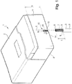
- the electrical equipment is here an electrical meter 1.
- the electrical meter 1 is intended to measure the electrical consumption of an electrical installation which is supplied by a distribution network.
- the electric meter 1 comprises a box 2 in which are integrated means for measuring the electrical energy consumed (current, voltage sensor (s), etc.), and connectors (screw cages). Each connector includes a screw cage which makes it possible to connect to the electric meter 1 a power cable 3 from the distribution network.
- the housing 2 includes a terminal cover 4.
- the terminal cover 4 is a removable part.
- the terminal cover 4 can only be removed by an operator of the electric power distributor or the manager of the distribution network. Terminal cover 4 prevents a user from accessing the connectors.
- Each cable 3 comprises a sheath 5 and an electrical conductor 6 surrounded by the sheath 5.
- the sheath 5 is an insulating envelope made for example with a polymer such as polyethylene or ethylene-propylene.
- the electrical conductor 6, or "core" of the cable 3, here comprises a plurality of conductive strands made for example of copper, steel or aluminum.
- the stripped portion 7 of the cable 3 extends between a free end 8 of the cable 3 and a shoulder 9 of the cable 3 formed by a sectioned end of the sheath 5.
- the reference length here is 17mm. This reference length is defined by standards or directives defined and imposed by the electrical energy distributor or by the distribution network operator.
- a verification device 10 for the length of the stripped portion 7 of the cable 3 is formed on a front face 11 of the terminal cover 4. It is noted that the verification device could also be positioned on another face of the terminal cover 4, for example on an inner face of the terminal cover.
- the verification device 10 includes a first reception space.
- the first reception space is a first cavity 12 formed on the front face 11 of the terminal cover 4.
- the first cavity 12 has the shape of a portion of cylinder of circular section and axis X, said cylinder being cut by a plane parallel to the X axis.
- the cylinder has a radius slightly greater than the radius of the stripped portion 7, that is to say the radius of the electrical conductor 6.
- the first cavity 12 has a length equal to the reference length, that is to say here at 17mm.
- the axis X is parallel to a height h of the front face 11 of the terminal cover 4.
- the first cavity 12 therefore extends parallel to the height h of the terminal cover 4 from an edge 14 of the terminal cover 4.
- the depth of the first cavity 12 is here equal to half the radius of the section of the cylinder.
- the depth here is between 1 and 2mm, and is advantageously equal to 1.5mm.
- the verification device 10 comprises a first housing element, in this case a bottom 16 of the first cavity 12, and a second housing element, in this case the edge 14 of the terminal cover 4.
- the bottom 16 and the edge 14 delimit the first cavity 12 in length, so that they are spaced from the reference length.
- the operator dismantles the terminal cover 4 to access the connectors of the electric meter 1.
- the operator uses the verification device 10 of the terminal cover 4 to verify that the length L of the stripped portion 7 is equal to the reference length.
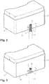
- the operator grasps in one hand the terminal cover 4, grasps the cable 3 in his other hand, and inserts the stripped portion 7 of the cable 3 in the first reception space, that is to say in the first cavity 12.
- the stripped portion 7 when the stripped portion 7 is inserted into the first cavity 12, if the stripped portion 7 is too long, the free end 8 of the cable 3 comes to bear against the bottom 16 of the first cavity 12.
- the shoulder 9 of the cable 3, for its part, is positioned above the edge 14 of the terminal cover 4, that is to say that the shoulder 9 of the cable 3 is not located at the edge 14 of the terminal cover 4, but that the stripped portion 7 protrudes from the edge 14 of the terminal cover 4 and that the shoulder 9 of the cable 3 is located beyond the edge 14 of the terminal cover 4.
- the bottom 16 of the first cavity 12 therefore forms a stop against which abuts a first cable element, which is in this case the free end 8 of the cable 3.
- the edge 14 of the terminal cover 4 forms a mark which allows the operator to make a visual comparison between the position of a second cable element, in this case the shoulder 9 of the cable 3, and the position of the marker, and therefore between the length of the stripped portion 7 of cable 3 and the reference length.
- the operator reduces the length of the stripped portion 7 by cutting it near the free end 8 of the cable 3. He again checks that the length of the stripped portion 7 of the cable 3 corresponds well to the reference length and, if this is the case, it connects the stripped portion 7 of the cable 3 to the corresponding connector of the electric meter 1.
- the edge 14 of the terminal cover 4 forms a stop against which abuts a first cable element, which is the shoulder 9 of the cable 3.
- the bottom 16 of the first cavity 12 forms a mark which allows the 'operator to make a visual comparison between the position of a second cable element, which is the free end 8 of the cable 3, and the position of the mark.
- the stripped portion 7 of the cable 3 is therefore positioned very easily and very conveniently in the first cavity 12.
- longitudinal grooves 18, parallel to the axis X of the cylinder, are formed in the first cavity 12. These grooves 18 improve the retention of the stripped portion 7 in the first cavity 12, and define a shape which resembles to the strands of the electrical conductor 6 of the cable 3. Intuitively, the operator understands how to position the stripped portion 7 to check its length.
- the terminal cover 4 once dismantled, is a “free” part, of small bulk, of low mass, and therefore very easy to handle.
- the terminal cover 4 is used here as a tool for verifying the length of the stripped portion 7. This tool is simple to use and very intuitive. Furthermore, as the tool is formed by the terminal cover 4 itself, it is very inexpensive and it avoids the operator having to use and permanently transport a specific tool to achieve an equivalent level of precision.
- the verification device according to the invention 10 is much more reliable than a simple index which would be marked on the terminal cover by etching.
- Such an index could for example be a double arrow having a length equal to the reference length and extending from an edge of the terminal cover parallel to a height thereof.
- This marking by engraving does not ensure a reliable verification of the stripping of the cable.
- the low thickness of the engraving makes the engraving difficult to distinguish from the rest of the terminal cover and the housing of the electric meter.
- the verification is therefore not reliable, in particular when the electric meter is dirty or is positioned in a room with little light.
- the verification device according to the invention 10 is much more reliable than a simple index which would be marked on the terminal cover by inked printing.
- a simple index could be a double arrow having a length equal to the reference length and extending from an edge of the terminal cover parallel to a height thereof.
- the verification device 10 is therefore more reliable and less expensive than the two solutions which have just been described briefly (engraving and printing).
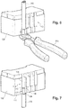
- the electrical equipment according to a second embodiment of the invention is again an electric meter 101.
- the electric meter 101 comprises a housing 102 comprising a removable terminal cover 104.
- the terminal cover 104 comprises a verification device 110 with a length L of the stripped portion 107 of a cable 103.
- the verification device 110 comprises a first reception space and a second reception space.
- the first reception space is a first cavity 112 formed on the front face 111 of the terminal cover 104.
- the shape of the first cavity 112 is a portion of the first cylinder cut by a plane parallel to an axis X1 of the first cylinder.
- the axis X1 is parallel to the height of the front face 111 of the terminal cover 104.
- the first cavity 112 extends parallel to the height of the terminal cover 104 from an edge 114 of the terminal cover 104.
- the first cavity 112 has a length equal to the reference length, that is to say here at 17mm.
- the first cylinder has a radius slightly greater than the radius of the stripped portion 107, that is to say the radius of the electrical conductor 106 of the cable 103.
- the second reception space is a second cavity 113 formed on the front face 111 of the terminal cover 104.
- the shape of the second cavity 113 is a portion of cylinder cut by a plane parallel to an axis of the cylinder.
- the second cavity 113 extends parallel to the height of the terminal cover 104 from a first end of the first cavity 112 which is opposite to the edge 114 of the terminal cover 104.
- the axis X2 coincides with the axis X1, so that the first cavity 112 and the second cavity 113 are coaxial.
- the second cylinder has a radius slightly greater than the radius of the cable 103 including the sheath 105.
- the radius of the second cylinder is therefore greater than that of the first cylinder so that a housing shoulder 117 is formed at the limit between the first cavity 112 and the second cavity 113: the first cavity 112 opens into the second cavity 113 in widening.
- the depth of the first cavity 112 is similar to that of the first cavity 12 of the first embodiment.
- the depth of the second cavity 113 is greater than that of the first cavity 112: the ratio between the depth of the first cavity 112 and the depth of the second cavity 113 is here equal to the ratio between the radius of the first cylinder and the radius of the second cylinder (but this is not necessary).
- the housing shoulder 117 and the edge 114 delimit the first cavity 112 in length, so that they are spaced from the reference length.
- the first cavity 112 is again intended to receive the stripped portion 107 of the cable 103.
- the second cavity 113 is intended to accommodate a non-stripped portion of the cable 103.
- the free end 108 of the cable protrudes from the edge 114 of the terminal cover 104 (that is to say from the second end of the first cavity 112 which is opposite to the second cavity 113).
- the operator can then, with pliers 120, cut the end of the free end 108 of the cable 103 which protrudes from the edge 114 so that the length of the stripped portion 107 is equal to the reference length (that is i.e. the length of the first cavity 112).
- the housing shoulder 117 therefore forms a stop against which a first cable element is positioned, in this case the shoulder 109 of the cable 103.
- the edge 114 of the terminal cover 104 forms a mark which allows a visual comparison between the position of a second cable element, in this case the free end 108 of the cable 103, and the position of the mark, and therefore between the length of the stripped portion 107 of the cable 103 and the reference length.
- the operator when the operator has stripped the cable 103, he can also insert the end 108 of the cable 103 into the first cavity 112 from the edge 114 of the terminal cover 104, that is to say via the second end of the first cavity 112. It then brings the shoulder 109 of the cable 103 into abutment against the edge 114 of the terminal cover 104.
- the non-stripped portion of the cable 103 is therefore located outside of the terminal cover 104 and the stripped portion 107 is positioned in the first cavity 112 of the verification device 110 (as well as in the second cavity 113 if the stripped portion 107 is long enough).
- the stripped portion 107 of the cable 103 arrives precisely at the level of the housing shoulder 117, which means that the length of the stripped portion 107 is equal to the reference length, and is therefore correct.
- the edge 114 of the terminal cover 104 therefore forms a stop against which a first cable element is positioned, in this case the shoulder 109 of the cable 103.
- the housing shoulder 117 forms a mark which allows a visual comparison between the position of a second cable element, in this case the free end 108 of the cable 103, and the position of the mark, and therefore between the length of the stripped portion 107 of the cable 103 and the length reference.
- the face of the terminal cover not to include one but a plurality of verification devices 110.
- the verification devices 110 may all be identical, as is the case with the figures 4 to 7 , and be used by the operator to check all the cables 103 coming from the distribution network at the same time. For example, if the line connected to the meter is a three-phase line comprising three phase cables and a neutral cable, there may be four identical verification devices 110 each intended to verify the length of the stripped portion 107 of a cable 103.
- the length, width and depth of the second cavity 113 can vary, in particular to take into account different diameters of the cable and / or different thicknesses of the sheath.
- the width and depth of the first cavity 112 can also vary depending on the verification devices 110, to take into account different diameters of the electrical conductor of the cable.
- the length of the first cavity 112 could also be different depending on the verification devices 110, in the case where the reference length can vary, for example according to the type of cable or else according to the type of electric meter. In this case, one could perfectly plan to add indications to the terminal cover 104 to explain which verification device to use according to the circumstances.
- the electrical equipment in which the invention is implemented is not necessarily an electric meter, but could be another equipment to which a stripped portion of a cable is capable of being connected.
- the housing part on which the verification device is formed is not necessarily removable.
Landscapes
- Engineering & Computer Science (AREA)
- Manufacturing & Machinery (AREA)
- Connector Housings Or Holding Contact Members (AREA)
Applications Claiming Priority (1)
| Application Number | Priority Date | Filing Date | Title |
|---|---|---|---|
| FR1873940A FR3091050A1 (fr) | 2018-12-21 | 2018-12-21 | Equipement électrique comprenant un dispositif de vérification du dénudage d’un câble. |
Publications (2)
| Publication Number | Publication Date |
|---|---|
| EP3671980A1 true EP3671980A1 (de) | 2020-06-24 |
| EP3671980B1 EP3671980B1 (de) | 2022-09-07 |
Family
ID=67185148
Family Applications (1)
| Application Number | Title | Priority Date | Filing Date |
|---|---|---|---|
| EP19214912.8A Active EP3671980B1 (de) | 2018-12-21 | 2019-12-10 | Elektrisches gerät, das eine überprüfungsvorrichtung für die abisolierung von kabeln umfasst und verfahren zum anschliessen eines kabels an ein elektrisches gerät |
Country Status (3)
| Country | Link |
|---|---|
| EP (1) | EP3671980B1 (de) |
| CN (1) | CN111355112B (de) |
| FR (1) | FR3091050A1 (de) |
Families Citing this family (1)
| Publication number | Priority date | Publication date | Assignee | Title |
|---|---|---|---|---|
| CN113904200A (zh) * | 2021-10-25 | 2022-01-07 | 中国电子科技集团公司第二十九研究所 | 一种同轴电缆内导体长度修剪隔片及方法 |
Citations (1)
| Publication number | Priority date | Publication date | Assignee | Title |
|---|---|---|---|---|
| WO2018116471A1 (ja) * | 2016-12-22 | 2018-06-28 | オリンパス株式会社 | ケーブル構造体、実装モジュールおよび内視鏡 |
Family Cites Families (8)
| Publication number | Priority date | Publication date | Assignee | Title |
|---|---|---|---|---|
| GB2225673A (en) * | 1988-10-27 | 1990-06-06 | Egerton A C Ltd | Cable stripper |
| JPH08138825A (ja) * | 1994-11-02 | 1996-05-31 | Sumitomo Wiring Syst Ltd | 皮剥圧着機における起動装置 |
| US6496271B1 (en) * | 1999-10-28 | 2002-12-17 | Oes, Inc. | Wire and seal profile analyzer |
| US7171712B2 (en) * | 2004-07-07 | 2007-02-06 | Ideal Industries, Inc. | Wire stripper with strip length scale |
| CN105610096A (zh) * | 2013-07-16 | 2016-05-25 | 国家电网公司 | 制作方便、准确的高压电缆头划线切割定位方法 |
| CN104466809B (zh) * | 2013-09-23 | 2017-11-21 | 国家电网公司 | 剥线装置 |
| CN104638498B (zh) * | 2014-12-30 | 2017-09-22 | 昆山恩都照明有限公司 | 线头长度定位剪裁装置 |
| CN207098472U (zh) * | 2017-06-23 | 2018-03-13 | 国网河南鄢陵县供电公司 | 一种具有不同剥线长度的剥线装置 |
-
2018
- 2018-12-21 FR FR1873940A patent/FR3091050A1/fr not_active Ceased
-
2019
- 2019-12-10 EP EP19214912.8A patent/EP3671980B1/de active Active
- 2019-12-20 CN CN201911324870.3A patent/CN111355112B/zh active Active
Patent Citations (1)
| Publication number | Priority date | Publication date | Assignee | Title |
|---|---|---|---|---|
| WO2018116471A1 (ja) * | 2016-12-22 | 2018-06-28 | オリンパス株式会社 | ケーブル構造体、実装モジュールおよび内視鏡 |
Also Published As
| Publication number | Publication date |
|---|---|
| CN111355112A (zh) | 2020-06-30 |
| EP3671980B1 (de) | 2022-09-07 |
| FR3091050A1 (fr) | 2020-06-26 |
| CN111355112B (zh) | 2022-07-19 |
Similar Documents
| Publication | Publication Date | Title |
|---|---|---|
| EP2360792B1 (de) | Elektrischer Zwitterkontakt | |
| WO2005088773A1 (fr) | Partie de connecteur electrique etanche | |
| EP3657180B1 (de) | Magnetischer kern für stromsensor | |
| EP1891646A1 (de) | Elektrokabel mit externer markierung und verfahren zum crimpen eines kontaktkerns auf ein elektrokabel mit externer markierung | |
| EP3671980B1 (de) | Elektrisches gerät, das eine überprüfungsvorrichtung für die abisolierung von kabeln umfasst und verfahren zum anschliessen eines kabels an ein elektrisches gerät | |
| EP1445618B1 (de) | Vorrichtung zur Messung des fliessenden elektrischen Stromes | |
| EP3238224B1 (de) | Sicherungskasten für ein kraftfahrzeug | |
| CA2043580C (fr) | Procede pour relier un conducteur electrique a une broche d'un connecteur, et liaison electrique obtenue par mise en oeuvre de ce procede | |
| FR3125644A1 (fr) | Dispositif de connexion d’un terminal d’un module de batterie a un conducteur electrique | |
| FR2797353A1 (fr) | Connecteur electrique utlisant des organes penetrant dans l'isolation | |
| EP2849295B1 (de) | Elektrische Verteilungsanordnung mit einem mehrpoligen Stromverteilungskamm. | |
| FR3127645A1 (fr) | Substrat destiné à une mise en contact avec au moins une broche électrique d'une prise de charge | |
| FR3036858A1 (fr) | Connecteur electrique et dispositif de raccordement electrique | |
| EP2518831A1 (de) | Anschlussmuffe für elektrische Kabel | |
| EP1058344A1 (de) | Mobile Verbindungsanordnung | |
| EP2850697B1 (de) | Verbinder für abgeschirmtes stromkabel und entsprechendes montageverfahren | |
| FR3112666A1 (fr) | Batterie de secours pourvue d’un connecteur électrique | |
| EP4026407B1 (de) | Anordnung mit einer karte, einem elektrischen bauelement und einem elektrischen steckverbinder | |
| FR3160822A1 (fr) | Dispositif d’isolation pour un compartiment à pile, compartiment à pile, appareil électrique et disjoncteur électrique associés | |
| WO2023218030A1 (fr) | Outil de liaison électrique assurant un passage de courant optimum par serrage d'une âme d'un fil à relier | |
| FR3135573A1 (fr) | outil de liaison électrique assurant un passage de courant optimum par serrage d’une âme d’un fil à relier | |
| EP2272135B1 (de) | Einrichtung zur verhinderung der erzeugung eines elektrischen bogens zwischen zwei leitfähigen elementen | |
| EP2536260B1 (de) | Gateway zwichen einem localen Netzwerk und einem globalen Netwerk | |
| FR2656469A1 (fr) | Borne de contact electrique et connecteur en comportant application. | |
| EP0905817B1 (de) | Verbindungsvorrichtung mit Schneidklemmkontaktelement |
Legal Events
| Date | Code | Title | Description |
|---|---|---|---|
| PUAI | Public reference made under article 153(3) epc to a published international application that has entered the european phase |
Free format text: ORIGINAL CODE: 0009012 |
|
| STAA | Information on the status of an ep patent application or granted ep patent |
Free format text: STATUS: THE APPLICATION HAS BEEN PUBLISHED |
|
| AK | Designated contracting states |
Kind code of ref document: A1 Designated state(s): AL AT BE BG CH CY CZ DE DK EE ES FI FR GB GR HR HU IE IS IT LI LT LU LV MC MK MT NL NO PL PT RO RS SE SI SK SM TR |
|
| AX | Request for extension of the european patent |
Extension state: BA ME |
|
| STAA | Information on the status of an ep patent application or granted ep patent |
Free format text: STATUS: REQUEST FOR EXAMINATION WAS MADE |
|
| 17P | Request for examination filed |
Effective date: 20201204 |
|
| RBV | Designated contracting states (corrected) |
Designated state(s): AL AT BE BG CH CY CZ DE DK EE ES FI FR GB GR HR HU IE IS IT LI LT LU LV MC MK MT NL NO PL PT RO RS SE SI SK SM TR |
|
| STAA | Information on the status of an ep patent application or granted ep patent |
Free format text: STATUS: EXAMINATION IS IN PROGRESS |
|
| RIC1 | Information provided on ipc code assigned before grant |
Ipc: H01R 43/28 20060101AFI20210322BHEP Ipc: G01B 5/00 20060101ALI20210322BHEP Ipc: G01B 5/02 20060101ALI20210322BHEP Ipc: H02G 15/02 20060101ALI20210322BHEP Ipc: H02G 1/12 20060101ALI20210322BHEP |
|
| 17Q | First examination report despatched |
Effective date: 20210415 |
|
| GRAP | Despatch of communication of intention to grant a patent |
Free format text: ORIGINAL CODE: EPIDOSNIGR1 |
|
| STAA | Information on the status of an ep patent application or granted ep patent |
Free format text: STATUS: GRANT OF PATENT IS INTENDED |
|
| INTG | Intention to grant announced |
Effective date: 20211028 |
|
| GRAJ | Information related to disapproval of communication of intention to grant by the applicant or resumption of examination proceedings by the epo deleted |
Free format text: ORIGINAL CODE: EPIDOSDIGR1 |
|
| STAA | Information on the status of an ep patent application or granted ep patent |
Free format text: STATUS: EXAMINATION IS IN PROGRESS |
|
| INTC | Intention to grant announced (deleted) | ||
| GRAP | Despatch of communication of intention to grant a patent |
Free format text: ORIGINAL CODE: EPIDOSNIGR1 |
|
| STAA | Information on the status of an ep patent application or granted ep patent |
Free format text: STATUS: GRANT OF PATENT IS INTENDED |
|
| INTG | Intention to grant announced |
Effective date: 20220401 |
|
| GRAS | Grant fee paid |
Free format text: ORIGINAL CODE: EPIDOSNIGR3 |
|
| GRAA | (expected) grant |
Free format text: ORIGINAL CODE: 0009210 |
|
| STAA | Information on the status of an ep patent application or granted ep patent |
Free format text: STATUS: THE PATENT HAS BEEN GRANTED |
|
| AK | Designated contracting states |
Kind code of ref document: B1 Designated state(s): AL AT BE BG CH CY CZ DE DK EE ES FI FR GB GR HR HU IE IS IT LI LT LU LV MC MK MT NL NO PL PT RO RS SE SI SK SM TR |
|
| REG | Reference to a national code |
Ref country code: GB Ref legal event code: FG4D Free format text: NOT ENGLISH |
|
| REG | Reference to a national code |
Ref country code: CH Ref legal event code: EP Ref country code: AT Ref legal event code: REF Ref document number: 1517838 Country of ref document: AT Kind code of ref document: T Effective date: 20220915 |
|
| REG | Reference to a national code |
Ref country code: DE Ref legal event code: R096 Ref document number: 602019019219 Country of ref document: DE |
|
| REG | Reference to a national code |
Ref country code: IE Ref legal event code: FG4D Free format text: LANGUAGE OF EP DOCUMENT: FRENCH |
|
| REG | Reference to a national code |
Ref country code: LT Ref legal event code: MG9D |
|
| REG | Reference to a national code |
Ref country code: NL Ref legal event code: MP Effective date: 20220907 |
|
| PG25 | Lapsed in a contracting state [announced via postgrant information from national office to epo] |
Ref country code: SE Free format text: LAPSE BECAUSE OF FAILURE TO SUBMIT A TRANSLATION OF THE DESCRIPTION OR TO PAY THE FEE WITHIN THE PRESCRIBED TIME-LIMIT Effective date: 20220907 Ref country code: RS Free format text: LAPSE BECAUSE OF FAILURE TO SUBMIT A TRANSLATION OF THE DESCRIPTION OR TO PAY THE FEE WITHIN THE PRESCRIBED TIME-LIMIT Effective date: 20220907 Ref country code: NO Free format text: LAPSE BECAUSE OF FAILURE TO SUBMIT A TRANSLATION OF THE DESCRIPTION OR TO PAY THE FEE WITHIN THE PRESCRIBED TIME-LIMIT Effective date: 20221207 Ref country code: LV Free format text: LAPSE BECAUSE OF FAILURE TO SUBMIT A TRANSLATION OF THE DESCRIPTION OR TO PAY THE FEE WITHIN THE PRESCRIBED TIME-LIMIT Effective date: 20220907 Ref country code: LT Free format text: LAPSE BECAUSE OF FAILURE TO SUBMIT A TRANSLATION OF THE DESCRIPTION OR TO PAY THE FEE WITHIN THE PRESCRIBED TIME-LIMIT Effective date: 20220907 Ref country code: FI Free format text: LAPSE BECAUSE OF FAILURE TO SUBMIT A TRANSLATION OF THE DESCRIPTION OR TO PAY THE FEE WITHIN THE PRESCRIBED TIME-LIMIT Effective date: 20220907 |
|
| REG | Reference to a national code |
Ref country code: AT Ref legal event code: MK05 Ref document number: 1517838 Country of ref document: AT Kind code of ref document: T Effective date: 20220907 |
|
| PG25 | Lapsed in a contracting state [announced via postgrant information from national office to epo] |
Ref country code: HR Free format text: LAPSE BECAUSE OF FAILURE TO SUBMIT A TRANSLATION OF THE DESCRIPTION OR TO PAY THE FEE WITHIN THE PRESCRIBED TIME-LIMIT Effective date: 20220907 Ref country code: GR Free format text: LAPSE BECAUSE OF FAILURE TO SUBMIT A TRANSLATION OF THE DESCRIPTION OR TO PAY THE FEE WITHIN THE PRESCRIBED TIME-LIMIT Effective date: 20221208 |
|
| PG25 | Lapsed in a contracting state [announced via postgrant information from national office to epo] |
Ref country code: SM Free format text: LAPSE BECAUSE OF FAILURE TO SUBMIT A TRANSLATION OF THE DESCRIPTION OR TO PAY THE FEE WITHIN THE PRESCRIBED TIME-LIMIT Effective date: 20220907 Ref country code: RO Free format text: LAPSE BECAUSE OF FAILURE TO SUBMIT A TRANSLATION OF THE DESCRIPTION OR TO PAY THE FEE WITHIN THE PRESCRIBED TIME-LIMIT Effective date: 20220907 Ref country code: PT Free format text: LAPSE BECAUSE OF FAILURE TO SUBMIT A TRANSLATION OF THE DESCRIPTION OR TO PAY THE FEE WITHIN THE PRESCRIBED TIME-LIMIT Effective date: 20230109 Ref country code: ES Free format text: LAPSE BECAUSE OF FAILURE TO SUBMIT A TRANSLATION OF THE DESCRIPTION OR TO PAY THE FEE WITHIN THE PRESCRIBED TIME-LIMIT Effective date: 20220907 Ref country code: CZ Free format text: LAPSE BECAUSE OF FAILURE TO SUBMIT A TRANSLATION OF THE DESCRIPTION OR TO PAY THE FEE WITHIN THE PRESCRIBED TIME-LIMIT Effective date: 20220907 Ref country code: AT Free format text: LAPSE BECAUSE OF FAILURE TO SUBMIT A TRANSLATION OF THE DESCRIPTION OR TO PAY THE FEE WITHIN THE PRESCRIBED TIME-LIMIT Effective date: 20220907 |
|
| PG25 | Lapsed in a contracting state [announced via postgrant information from national office to epo] |
Ref country code: SK Free format text: LAPSE BECAUSE OF FAILURE TO SUBMIT A TRANSLATION OF THE DESCRIPTION OR TO PAY THE FEE WITHIN THE PRESCRIBED TIME-LIMIT Effective date: 20220907 Ref country code: PL Free format text: LAPSE BECAUSE OF FAILURE TO SUBMIT A TRANSLATION OF THE DESCRIPTION OR TO PAY THE FEE WITHIN THE PRESCRIBED TIME-LIMIT Effective date: 20220907 Ref country code: IS Free format text: LAPSE BECAUSE OF FAILURE TO SUBMIT A TRANSLATION OF THE DESCRIPTION OR TO PAY THE FEE WITHIN THE PRESCRIBED TIME-LIMIT Effective date: 20230107 Ref country code: EE Free format text: LAPSE BECAUSE OF FAILURE TO SUBMIT A TRANSLATION OF THE DESCRIPTION OR TO PAY THE FEE WITHIN THE PRESCRIBED TIME-LIMIT Effective date: 20220907 |
|
| REG | Reference to a national code |
Ref country code: DE Ref legal event code: R097 Ref document number: 602019019219 Country of ref document: DE |
|
| PG25 | Lapsed in a contracting state [announced via postgrant information from national office to epo] |
Ref country code: NL Free format text: LAPSE BECAUSE OF FAILURE TO SUBMIT A TRANSLATION OF THE DESCRIPTION OR TO PAY THE FEE WITHIN THE PRESCRIBED TIME-LIMIT Effective date: 20220907 Ref country code: AL Free format text: LAPSE BECAUSE OF FAILURE TO SUBMIT A TRANSLATION OF THE DESCRIPTION OR TO PAY THE FEE WITHIN THE PRESCRIBED TIME-LIMIT Effective date: 20220907 |
|
| PLBE | No opposition filed within time limit |
Free format text: ORIGINAL CODE: 0009261 |
|
| STAA | Information on the status of an ep patent application or granted ep patent |
Free format text: STATUS: NO OPPOSITION FILED WITHIN TIME LIMIT |
|
| PG25 | Lapsed in a contracting state [announced via postgrant information from national office to epo] |
Ref country code: DK Free format text: LAPSE BECAUSE OF FAILURE TO SUBMIT A TRANSLATION OF THE DESCRIPTION OR TO PAY THE FEE WITHIN THE PRESCRIBED TIME-LIMIT Effective date: 20220907 |
|
| REG | Reference to a national code |
Ref country code: CH Ref legal event code: PL |
|
| 26N | No opposition filed |
Effective date: 20230608 |
|
| REG | Reference to a national code |
Ref country code: BE Ref legal event code: MM Effective date: 20221231 |
|
| PG25 | Lapsed in a contracting state [announced via postgrant information from national office to epo] |
Ref country code: SI Free format text: LAPSE BECAUSE OF FAILURE TO SUBMIT A TRANSLATION OF THE DESCRIPTION OR TO PAY THE FEE WITHIN THE PRESCRIBED TIME-LIMIT Effective date: 20220907 Ref country code: LU Free format text: LAPSE BECAUSE OF NON-PAYMENT OF DUE FEES Effective date: 20221210 |
|
| PG25 | Lapsed in a contracting state [announced via postgrant information from national office to epo] |
Ref country code: LI Free format text: LAPSE BECAUSE OF NON-PAYMENT OF DUE FEES Effective date: 20221231 Ref country code: IE Free format text: LAPSE BECAUSE OF NON-PAYMENT OF DUE FEES Effective date: 20221210 Ref country code: CH Free format text: LAPSE BECAUSE OF NON-PAYMENT OF DUE FEES Effective date: 20221231 |
|
| PG25 | Lapsed in a contracting state [announced via postgrant information from national office to epo] |
Ref country code: BE Free format text: LAPSE BECAUSE OF NON-PAYMENT OF DUE FEES Effective date: 20221231 |
|
| PG25 | Lapsed in a contracting state [announced via postgrant information from national office to epo] |
Ref country code: HU Free format text: LAPSE BECAUSE OF FAILURE TO SUBMIT A TRANSLATION OF THE DESCRIPTION OR TO PAY THE FEE WITHIN THE PRESCRIBED TIME-LIMIT; INVALID AB INITIO Effective date: 20191210 |
|
| PG25 | Lapsed in a contracting state [announced via postgrant information from national office to epo] |
Ref country code: CY Free format text: LAPSE BECAUSE OF FAILURE TO SUBMIT A TRANSLATION OF THE DESCRIPTION OR TO PAY THE FEE WITHIN THE PRESCRIBED TIME-LIMIT Effective date: 20220907 |
|
| PG25 | Lapsed in a contracting state [announced via postgrant information from national office to epo] |
Ref country code: MK Free format text: LAPSE BECAUSE OF FAILURE TO SUBMIT A TRANSLATION OF THE DESCRIPTION OR TO PAY THE FEE WITHIN THE PRESCRIBED TIME-LIMIT Effective date: 20220907 Ref country code: IT Free format text: LAPSE BECAUSE OF FAILURE TO SUBMIT A TRANSLATION OF THE DESCRIPTION OR TO PAY THE FEE WITHIN THE PRESCRIBED TIME-LIMIT Effective date: 20220907 |
|
| PG25 | Lapsed in a contracting state [announced via postgrant information from national office to epo] |
Ref country code: MC Free format text: LAPSE BECAUSE OF FAILURE TO SUBMIT A TRANSLATION OF THE DESCRIPTION OR TO PAY THE FEE WITHIN THE PRESCRIBED TIME-LIMIT Effective date: 20220907 |
|
| PG25 | Lapsed in a contracting state [announced via postgrant information from national office to epo] |
Ref country code: TR Free format text: LAPSE BECAUSE OF FAILURE TO SUBMIT A TRANSLATION OF THE DESCRIPTION OR TO PAY THE FEE WITHIN THE PRESCRIBED TIME-LIMIT Effective date: 20220907 Ref country code: MC Free format text: LAPSE BECAUSE OF FAILURE TO SUBMIT A TRANSLATION OF THE DESCRIPTION OR TO PAY THE FEE WITHIN THE PRESCRIBED TIME-LIMIT Effective date: 20220907 |
|
| PG25 | Lapsed in a contracting state [announced via postgrant information from national office to epo] |
Ref country code: BG Free format text: LAPSE BECAUSE OF FAILURE TO SUBMIT A TRANSLATION OF THE DESCRIPTION OR TO PAY THE FEE WITHIN THE PRESCRIBED TIME-LIMIT Effective date: 20220907 |
|
| PG25 | Lapsed in a contracting state [announced via postgrant information from national office to epo] |
Ref country code: MT Free format text: LAPSE BECAUSE OF FAILURE TO SUBMIT A TRANSLATION OF THE DESCRIPTION OR TO PAY THE FEE WITHIN THE PRESCRIBED TIME-LIMIT Effective date: 20220907 |
|
| PGFP | Annual fee paid to national office [announced via postgrant information from national office to epo] |
Ref country code: DE Payment date: 20251126 Year of fee payment: 7 |
|
| PGFP | Annual fee paid to national office [announced via postgrant information from national office to epo] |
Ref country code: GB Payment date: 20251120 Year of fee payment: 7 |
|
| PGFP | Annual fee paid to national office [announced via postgrant information from national office to epo] |
Ref country code: FR Payment date: 20251120 Year of fee payment: 7 |