EP1058344A1 - Mobile Verbindungsanordnung - Google Patents
Mobile Verbindungsanordnung Download PDFInfo
- Publication number
- EP1058344A1 EP1058344A1 EP00401214A EP00401214A EP1058344A1 EP 1058344 A1 EP1058344 A1 EP 1058344A1 EP 00401214 A EP00401214 A EP 00401214A EP 00401214 A EP00401214 A EP 00401214A EP 1058344 A1 EP1058344 A1 EP 1058344A1
- Authority
- EP
- European Patent Office
- Prior art keywords
- connection
- tubular
- mobile
- mobile connection
- contact element
- Prior art date
- Legal status (The legal status is an assumption and is not a legal conclusion. Google has not performed a legal analysis and makes no representation as to the accuracy of the status listed.)
- Granted
Links
Images

Classifications
-
- H—ELECTRICITY
- H01—ELECTRIC ELEMENTS
- H01R—ELECTRICALLY-CONDUCTIVE CONNECTIONS; STRUCTURAL ASSOCIATIONS OF A PLURALITY OF MUTUALLY-INSULATED ELECTRICAL CONNECTING ELEMENTS; COUPLING DEVICES; CURRENT COLLECTORS
- H01R4/00—Electrically-conductive connections between two or more conductive members in direct contact, i.e. touching one another; Means for effecting or maintaining such contact; Electrically-conductive connections having two or more spaced connecting locations for conductors and using contact members penetrating insulation
- H01R4/58—Electrically-conductive connections between two or more conductive members in direct contact, i.e. touching one another; Means for effecting or maintaining such contact; Electrically-conductive connections having two or more spaced connecting locations for conductors and using contact members penetrating insulation characterised by the form or material of the contacting members
- H01R4/60—Connections between or with tubular conductors
-
- H—ELECTRICITY
- H01—ELECTRIC ELEMENTS
- H01R—ELECTRICALLY-CONDUCTIVE CONNECTIONS; STRUCTURAL ASSOCIATIONS OF A PLURALITY OF MUTUALLY-INSULATED ELECTRICAL CONNECTING ELEMENTS; COUPLING DEVICES; CURRENT COLLECTORS
- H01R24/00—Two-part coupling devices, or either of their cooperating parts, characterised by their overall structure
- H01R24/28—Coupling parts carrying pins, blades or analogous contacts and secured only to wire or cable
- H01R24/30—Coupling parts carrying pins, blades or analogous contacts and secured only to wire or cable with additional earth or shield contacts
-
- H—ELECTRICITY
- H01—ELECTRIC ELEMENTS
- H01R—ELECTRICALLY-CONDUCTIVE CONNECTIONS; STRUCTURAL ASSOCIATIONS OF A PLURALITY OF MUTUALLY-INSULATED ELECTRICAL CONNECTING ELEMENTS; COUPLING DEVICES; CURRENT COLLECTORS
- H01R2103/00—Two poles
Definitions
- the present invention relates generally to apparatus commonly referred to as "mobile” as far as not being an integral part of any electrical appliance, and not being intended to be permanently installed on such an electrical appliance or on a any other support, they can be moved.
- It can therefore be either a plug or a socket outlet intervening in isolation at the end of an electric cable belonging to a cord extension, that of a power strip comprising in parallel a plurality of such plinths.
- a mobile connection device of the kind in cause has at least one contact element, such as a socket or pin, which is waiting for the intervention of a mobile connection device complementary, and at least one connection terminal, which is connected electrically to the contact element, and which, for the service thereof, is suitable for connection of any electrical conductor.
- the present invention relates more particularly to this terminal of connection, or, more generally, the connection means implemented works to ensure the necessary connection.
- Removable products must be fitted with connection terminals to screws, so that their implementation, that is to say their connection to a cable electric, can be easily done using a common tool, in this case a simple screwdriver, especially when reused.
- the present invention generally relates to a provision allowing on the contrary a certain standardization of these manufacturing and further leading to other advantages.
- a switchgear mobile such as a base or plug, of the kind comprising at least one element of contact, such as socket or pin, and at least one connection terminal, which is electrically connected to the contact element, and which is suitable for connection of any electrical conductor
- this mobile connection device being generally characterized in that the connection terminal has a tail by which it is force-fitted into an element tubular, and in that it is through this tubular element that this connection terminal is electrically connected to the contact element.
- connection terminals provided according to the invention are actually implemented, and these are, in practice, screw connection.
- this mobile connection device when this mobile connection device must constitute a non-removable product, these connection terminals are omitted, and the connection of the necessary electric cable conductors directly using the corresponding tubular elements, for example by crimping of these.
- the constituents used can advantageously and economically be the same in both cases.
- connection terminals provided according to the invention are actually implemented, it is advantageously possible, at assembly, to confer, without any particular operation, to one and / or the other of them, any orientation which would prove desirable.
- FIGS. 1-10 illustrate, by way of example, the case where the apparatus for mobile connection 10 according to the invention is a plug intended to be releasably located at one end of any electric cable, and, for example, that of an electric cable belonging to a extension cord not shown.
- this mechanism 11 is organized from a block of insulating material 12, and this forms, at its base, a plate 13 of which only the outer surface 14 is normally visible, the switchgear mobile connection 10 completed by a cover, not shown, which covers all.
- the following mobile connection device 10 the invention comprises at least one contact element 15P, 15T, such as a cell or pin, and at least one connection terminal 16P, 16T, which, according to arrangements described in more detail later, is electrically connected to the corresponding contact element 15P, 15T, which is specific to the connection of any electrical conductor belonging to the cable to which the assembly must be attached.
- the sheet that constitutes the mobile connection apparatus 10 according to the invention is, by way of example, a bipolar plug with earth connection.
- the mobile connection apparatus 10 comprises, therefore, in this embodiment, three contact elements 15P, 15T, to know two 15P contact elements that form pole pins, and a contact element 15T which forms a grounding socket.
- the contact elements 15P protrude parallel to each other on the outer surface 14 of the plate 13 of the block on insulating material 12, and the contact element 15T opens onto this outer surface 14.
- the mobile connection apparatus 10 has three connection terminals 16P, 16T, one per connection element contact 15P, 15T.
- the insulating material block 12 forms, projecting from the inner surface 18 of its plate 13, two housings 19P, which, both generally in the form of wells, extend parallel to each other the other, at a distance from each other, and which, we practice, are each respectively arranged directly above the 15P contact elements concerned.
- Each of these housings 19P has, laterally, for reasons specified later, a hole 20.
- the insulating material block 12 forms, also, on the inner surface 18 of its plate 13, there is a housing 19T.
- this housing 19'T is shaped general well, like the previous 19F housing.
- the housing 19T is open laterally on two sides opposites.
- the material block insulating 12 also forms a protrusion on the inner surface 18 of its plate 13, a pillar 22, which, in practice, is backed by the housing 19T of the 16T connection terminal, and from the top of which extends, in overhang, a gutter 23 intended to form, with a similar gutter provided for this purpose on the associated cover, a clean end for the passage of the cable to which the assembly must be attached.
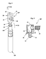
- connection terminal 16P, 16T has a tail 24 by which it is force-fitted into a tubular element 25P, 25T, and it is by through this tubular element 25P, 25T that this terminal of connection 16P, 16T is electrically connected to the contact element 15P, 15T corresponding.
- connection terminals 16P, 16T are all identical to each other.
- this connection terminal 16P is a connection terminal screw connection, i.e. a connection terminal comprising a body 26 metallic, which is perforated, longitudinally, of a bore 27, and which, transversely to it, has a tapped hole 29 with which engages a screw 30.
- the body 26 has, externally, in diametrically opposite positions, one with respect to the other, two flats 31, for its wedging in the housing 19P, 19T corresponding.
- the tail 24 extends parallel to bore 27.
- the tail 24 is not coaxial with the bore 27, because, to leave a maximum thickness of material on the side of the screw 30, this is off center in the body 26.
- the tail 24 is tapered at its free end, to facilitate its engagement in the corresponding tubular element 25P, 25T.
- the tail 24 is thus tapered by a chamfer 33 frustoconical.
- the tail 24 is in one piece with the body 26, in coming from one and the same room with him.
- the element tubular 25P, 25T is integral with the contact element 15P, 15T corresponding.
- the element of contact 15P is a pin
- the tubular element 25P extends back to back with him, being open at its end opposite to the own end of this contact element 15P.
- this tubular element 25P has, in cross section, a closed contour.
- this tubular element 25P forms, at its outlet, a flared collar 35, to further facilitate, the engagement of the tail 24 of the associated connection terminal 16P.
- the element of contact 15T is a cell
- the associated tubular element 25T belongs, with him, to the same metal blank 36 suitably cut and folded.
- this metal blank 36 comprises, overall, in a general U-shape, on the one hand, a middle part 37, on the same edge from which come, at a distance one of the other, two sections 38, 39 participating, for the first, in the constitution of the contact element 15T, and constituting, for the second, the tubular element 25T, and, on the other hand, two lateral wings 40, which, by a configuration in harpoon, are suitable for anchoring the assembly in the block of insulating material 12 and / or in the cover associated therewith.
- the tubular element 25T has, in cross section, a contour opened by a slot 41.
- This tubular element 25T can thus advantageously benefit, radially, of a certain elasticity.
- tubular element 25T thus formed results from the winding in cylinder on itself of a part of the corresponding pan 39 of the metal blank 36.
- the tail 24 of the connection terminals 16P, 16T a externally, a diameter substantially equal to the internal diameter of the tubular elements 25T, 25P, while being slightly higher than the latter.
- connection terminals 16P, 16T it is therefore necessary to exert a push on the connection terminals 16P, 16T to ensure the press fit of their tail 24 in the tubular elements 25P, 25T.
- connection terminals 16P, 16T on tubular elements 25P, 25T is firm and safe, and so are even for the electrical contact occurring between these connection terminals 16P, 16T and these tubular elements 25P, 25T.
- this tail 24 has a particular surface configuration.
- this tail 24 can be knurled or striated.
- the tubular element 25P of contact elements 15P has, in cross section, an outline opened by a slot, like the tubular element 25T associated with the element of 15T contact, especially when, instead of being massive, as shown, the pin constituting these contact elements 15P is hollow, resulting in example of cutting and rolling, like the tubular element 25T.
- connection 16P, 16T are omitted, and connection to conductors matching electrical is done simply by crimping the elements tubular 25P, 25T on the previously stripped end of the core conductor of these electrical conductors.
- connection terminals of connection implemented may be connection terminals of a other type, and, for example, connection terminals with direct engagement or insulation displacement connection terminals whenever possible and / or admissible.
- the field of application of the invention is not limited either no longer in case the mobile connection equipment concerned is a plug, but extends equally well in case it is a socket outlet or a power strip.
Landscapes
- Details Of Connecting Devices For Male And Female Coupling (AREA)
- Connector Housings Or Holding Contact Members (AREA)
- Coupling Device And Connection With Printed Circuit (AREA)
- Cable Accessories (AREA)
- Telephone Function (AREA)
- Motorcycle And Bicycle Frame (AREA)
- Connections Effected By Soldering, Adhesion, Or Permanent Deformation (AREA)
- Insulated Conductors (AREA)
- Connections By Means Of Piercing Elements, Nuts, Or Screws (AREA)
- Details Of Aerials (AREA)
- Combinations Of Printed Boards (AREA)
- Gyroscopes (AREA)
- Transducers For Ultrasonic Waves (AREA)
- Optical Couplings Of Light Guides (AREA)
Applications Claiming Priority (2)
| Application Number | Priority Date | Filing Date | Title |
|---|---|---|---|
| FR9906696A FR2794294B1 (fr) | 1999-05-27 | 1999-05-27 | Appareillage de connexion mobile |
| FR9906696 | 1999-05-27 |
Publications (2)
| Publication Number | Publication Date |
|---|---|
| EP1058344A1 true EP1058344A1 (de) | 2000-12-06 |
| EP1058344B1 EP1058344B1 (de) | 2008-03-05 |
Family
ID=9546059
Family Applications (1)
| Application Number | Title | Priority Date | Filing Date |
|---|---|---|---|
| EP00401214A Expired - Lifetime EP1058344B1 (de) | 1999-05-27 | 2000-05-03 | Mobile Verbindungsanordnung |
Country Status (11)
| Country | Link |
|---|---|
| US (2) | US6517388B1 (de) |
| EP (1) | EP1058344B1 (de) |
| AT (1) | ATE388503T1 (de) |
| DE (1) | DE60038206T2 (de) |
| ES (1) | ES2302495T3 (de) |
| FR (1) | FR2794294B1 (de) |
| HU (1) | HU223545B1 (de) |
| MA (1) | MA25116A1 (de) |
| PL (1) | PL197502B1 (de) |
| PT (1) | PT1058344E (de) |
| TR (1) | TR200001534A2 (de) |
Families Citing this family (4)
| Publication number | Priority date | Publication date | Assignee | Title |
|---|---|---|---|---|
| TW580213U (en) * | 2003-06-20 | 2004-03-11 | Speed Tech Corp | Improved structure for electric connector socket |
| JP5119005B2 (ja) * | 2008-03-04 | 2013-01-16 | 日本圧着端子製造株式会社 | ソケットコンタクト |
| US7607957B1 (en) * | 2008-11-17 | 2009-10-27 | Cheng Uei Precision Industry Co., Ltd. | Power plug |
| JP2017517112A (ja) * | 2014-05-28 | 2017-06-22 | マルチ−ホールディング アーゲー | 電気接続装置 |
Citations (2)
| Publication number | Priority date | Publication date | Assignee | Title |
|---|---|---|---|---|
| US5364281A (en) * | 1993-06-01 | 1994-11-15 | Philly D. Harrison | Electrical connector system for grounding member and ground wire |
| US5890925A (en) * | 1997-01-13 | 1999-04-06 | Litton Systems, Inc. | Electrical connector with screw-on or twist-on electrical contacts |
Family Cites Families (9)
| Publication number | Priority date | Publication date | Assignee | Title |
|---|---|---|---|---|
| US3501738A (en) * | 1966-04-08 | 1970-03-17 | Cons Electrodynamics Corp | Electrical connector arrangement |
| US3688248A (en) * | 1968-08-13 | 1972-08-29 | Henry John Modrey | Roller metal pin for use as electric connector or fastener |
| US3675181A (en) * | 1970-05-14 | 1972-07-04 | Betty U Lanham | Coaxial connector means affording alternate 90{20 {11 seizure |
| JPS5314104Y2 (de) * | 1972-04-19 | 1978-04-15 | ||
| US3818278A (en) * | 1972-08-07 | 1974-06-18 | Alcon Metal Prod Inc | Tube sockets for use with printed circuit boards |
| FR2291622A1 (fr) * | 1974-11-13 | 1976-06-11 | Sepm Sa | Dispositif de retenue par serrage a blocage elastique, constituant notamment une borne electrique |
| US4025150A (en) * | 1975-12-12 | 1977-05-24 | Gte Sylvania Incorporated | Equipment housing for communication system |
| JP3328560B2 (ja) * | 1997-10-24 | 2002-09-24 | ホシデン株式会社 | 陰極線管ソケット |
| US6109937A (en) * | 1999-02-19 | 2000-08-29 | Hubbell Incorporated | Four-sided ground contact assembly |
-
1999
- 1999-05-27 FR FR9906696A patent/FR2794294B1/fr not_active Expired - Fee Related
-
2000
- 2000-05-03 EP EP00401214A patent/EP1058344B1/de not_active Expired - Lifetime
- 2000-05-03 DE DE60038206T patent/DE60038206T2/de not_active Expired - Fee Related
- 2000-05-03 PT PT00401214T patent/PT1058344E/pt unknown
- 2000-05-03 AT AT00401214T patent/ATE388503T1/de not_active IP Right Cessation
- 2000-05-03 ES ES00401214T patent/ES2302495T3/es not_active Expired - Lifetime
- 2000-05-15 MA MA25975A patent/MA25116A1/fr unknown
- 2000-05-25 PL PL340278A patent/PL197502B1/pl not_active IP Right Cessation
- 2000-05-26 TR TR2000/01534A patent/TR200001534A2/xx unknown
- 2000-05-26 HU HU0002023A patent/HU223545B1/hu not_active IP Right Cessation
- 2000-05-30 US US09/583,722 patent/US6517388B1/en not_active Expired - Fee Related
-
2002
- 2002-10-01 US US10/260,502 patent/US6739917B2/en not_active Expired - Fee Related
Patent Citations (2)
| Publication number | Priority date | Publication date | Assignee | Title |
|---|---|---|---|---|
| US5364281A (en) * | 1993-06-01 | 1994-11-15 | Philly D. Harrison | Electrical connector system for grounding member and ground wire |
| US5890925A (en) * | 1997-01-13 | 1999-04-06 | Litton Systems, Inc. | Electrical connector with screw-on or twist-on electrical contacts |
Also Published As
| Publication number | Publication date |
|---|---|
| PL340278A1 (en) | 2000-12-04 |
| DE60038206D1 (de) | 2008-04-17 |
| US6517388B1 (en) | 2003-02-11 |
| US6739917B2 (en) | 2004-05-25 |
| EP1058344B1 (de) | 2008-03-05 |
| US20030027458A1 (en) | 2003-02-06 |
| FR2794294A1 (fr) | 2000-12-01 |
| FR2794294B1 (fr) | 2001-08-31 |
| TR200001534A3 (tr) | 2001-07-23 |
| TR200001534A2 (tr) | 2001-07-23 |
| HU0002023D0 (en) | 2000-08-28 |
| PL197502B1 (pl) | 2008-04-30 |
| HU223545B1 (hu) | 2004-09-28 |
| PT1058344E (pt) | 2008-06-09 |
| DE60038206T2 (de) | 2009-04-23 |
| HUP0002023A2 (hu) | 2001-02-28 |
| MA25116A1 (fr) | 2000-12-31 |
| ES2302495T3 (es) | 2008-07-16 |
| ATE388503T1 (de) | 2008-03-15 |
| HUP0002023A3 (en) | 2002-03-28 |
Similar Documents
| Publication | Publication Date | Title |
|---|---|---|
| EP2324534B1 (de) | Verbindungseinrichtung zwischen einem elektrischen kabel und einer leitenden struktur, insbesondere für eine stromrückkehrschaltung | |
| EP1054479A1 (de) | Anordnung für eine elektrische Verbindung zwischen einer koaxialen Leitung und einer gedrückten Schaltungskarte | |
| EP0574293A1 (de) | Elektrische Steckbuchse und deren Verwendung in einem Verbinder | |
| EP1608039A1 (de) | Selbstabisolierende Verbindungsklemme und Vorrichtung mit einer solchen Klemme | |
| EP1058344B1 (de) | Mobile Verbindungsanordnung | |
| EP2983245A1 (de) | Anschlussleiste für erdungen | |
| EP0697749B1 (de) | Schnellschneidklemmverbinder | |
| FR2523366A1 (fr) | Support de fusible | |
| EP1147574B1 (de) | Koaxiale kabelverbindungseinrichtung | |
| EP2518831A1 (de) | Anschlussmuffe für elektrische Kabel | |
| EP1650831B1 (de) | Kabelschuh für eine elektrische Verbindung mit einem verjüngten Abschnitt | |
| FR2623024A1 (fr) | Connecteur auto-denudant pour conducteur electrique isole | |
| EP0172779A1 (de) | Mehrpoliger elektrischer Verbinder | |
| FR2779278A1 (fr) | Mecanisme de connexion, en particulier pour sortie de cable ou derivation | |
| FR2567689A1 (fr) | Pince a denuder | |
| FR2608850A1 (fr) | Boitier de raccordement pour cables electriques | |
| EP0720250A1 (de) | Kraftfahrzeugantenne und Anpassungsvorrichtung mit aktiver Impedanz für eine solche Antenne | |
| FR2771555A1 (fr) | Linguet destine a etre serti a l'extremite d'un fil electrique | |
| FR2717009A1 (fr) | Dispositif de connexion, et tête connectrice pour piquet de terre comportant un tel dispositif de connexion. | |
| FR2882469A1 (fr) | Dispositif de connexion a un conducteur recouvert d'une couche isolante et ensemble le comportant | |
| EP0398770A1 (de) | Koaxiale Kabelverbindungseinrichtung, insbesondere für die Verbindung einer Antenne an einer Autoradiostelle | |
| WO2021209628A1 (fr) | Dispositif d'interconnexion électrique pour mise à la terre de conducteurs électriques | |
| FR2637419A1 (fr) | Connecteur auto-denudant, et appareillage electrique equipe d'au moins un tel connecteur | |
| FR2917245A1 (fr) | Dispositif de raccordement entre un fil electrique ecrante et un fil de terre. | |
| WO2021122405A1 (fr) | Procédé de fixation d'un connecteur électrique prévu à une extrémité d'un câble électrique à une borne électrique, support intermédiaire correspondant et dispositif comportant un tel support intermédiaire |
Legal Events
| Date | Code | Title | Description |
|---|---|---|---|
| PUAI | Public reference made under article 153(3) epc to a published international application that has entered the european phase |
Free format text: ORIGINAL CODE: 0009012 |
|
| AK | Designated contracting states |
Kind code of ref document: A1 Designated state(s): AT BE CH CY DE DK ES FI FR GB GR IE IT LI LU MC NL PT SE |
|
| AX | Request for extension of the european patent |
Free format text: AL;LT;LV;MK;RO;SI |
|
| 17P | Request for examination filed |
Effective date: 20010512 |
|
| AKX | Designation fees paid |
Free format text: AT BE CH CY DE DK ES FI FR GB GR IE IT LI LU MC NL PT SE |
|
| GRAP | Despatch of communication of intention to grant a patent |
Free format text: ORIGINAL CODE: EPIDOSNIGR1 |
|
| GRAS | Grant fee paid |
Free format text: ORIGINAL CODE: EPIDOSNIGR3 |
|
| GRAA | (expected) grant |
Free format text: ORIGINAL CODE: 0009210 |
|
| AK | Designated contracting states |
Kind code of ref document: B1 Designated state(s): AT BE CH CY DE DK ES FI FR GB GR IE IT LI LU MC NL PT SE |
|
| REG | Reference to a national code |
Ref country code: GB Ref legal event code: FG4D Free format text: NOT ENGLISH |
|
| REG | Reference to a national code |
Ref country code: CH Ref legal event code: EP |
|
| REG | Reference to a national code |
Ref country code: IE Ref legal event code: FG4D Free format text: LANGUAGE OF EP DOCUMENT: FRENCH |
|
| REF | Corresponds to: |
Ref document number: 60038206 Country of ref document: DE Date of ref document: 20080417 Kind code of ref document: P |
|
| REG | Reference to a national code |
Ref country code: PT Ref legal event code: SC4A Free format text: AVAILABILITY OF NATIONAL TRANSLATION Effective date: 20080529 |
|
| REG | Reference to a national code |
Ref country code: ES Ref legal event code: FG2A Ref document number: 2302495 Country of ref document: ES Kind code of ref document: T3 |
|
| PG25 | Lapsed in a contracting state [announced via postgrant information from national office to epo] |
Ref country code: FI Free format text: LAPSE BECAUSE OF FAILURE TO SUBMIT A TRANSLATION OF THE DESCRIPTION OR TO PAY THE FEE WITHIN THE PRESCRIBED TIME-LIMIT Effective date: 20080305 |
|
| NLV1 | Nl: lapsed or annulled due to failure to fulfill the requirements of art. 29p and 29m of the patents act | ||
| REG | Reference to a national code |
Ref country code: IE Ref legal event code: FD4D |
|
| PG25 | Lapsed in a contracting state [announced via postgrant information from national office to epo] |
Ref country code: NL Free format text: LAPSE BECAUSE OF FAILURE TO SUBMIT A TRANSLATION OF THE DESCRIPTION OR TO PAY THE FEE WITHIN THE PRESCRIBED TIME-LIMIT Effective date: 20080305 Ref country code: SE Free format text: LAPSE BECAUSE OF FAILURE TO SUBMIT A TRANSLATION OF THE DESCRIPTION OR TO PAY THE FEE WITHIN THE PRESCRIBED TIME-LIMIT Effective date: 20080605 |
|
| BERE | Be: lapsed |
Owner name: LEGRAND SNC Effective date: 20080531 Owner name: LEGRAND Effective date: 20080531 |
|
| PG25 | Lapsed in a contracting state [announced via postgrant information from national office to epo] |
Ref country code: MC Free format text: LAPSE BECAUSE OF NON-PAYMENT OF DUE FEES Effective date: 20080531 |
|
| REG | Reference to a national code |
Ref country code: CH Ref legal event code: PL |
|
| PLBE | No opposition filed within time limit |
Free format text: ORIGINAL CODE: 0009261 |
|
| STAA | Information on the status of an ep patent application or granted ep patent |
Free format text: STATUS: NO OPPOSITION FILED WITHIN TIME LIMIT |
|
| PG25 | Lapsed in a contracting state [announced via postgrant information from national office to epo] |
Ref country code: LI Free format text: LAPSE BECAUSE OF NON-PAYMENT OF DUE FEES Effective date: 20080531 Ref country code: IE Free format text: LAPSE BECAUSE OF FAILURE TO SUBMIT A TRANSLATION OF THE DESCRIPTION OR TO PAY THE FEE WITHIN THE PRESCRIBED TIME-LIMIT Effective date: 20080305 Ref country code: CH Free format text: LAPSE BECAUSE OF NON-PAYMENT OF DUE FEES Effective date: 20080531 Ref country code: DK Free format text: LAPSE BECAUSE OF FAILURE TO SUBMIT A TRANSLATION OF THE DESCRIPTION OR TO PAY THE FEE WITHIN THE PRESCRIBED TIME-LIMIT Effective date: 20080305 |
|
| 26N | No opposition filed |
Effective date: 20081208 |
|
| GBPC | Gb: european patent ceased through non-payment of renewal fee |
Effective date: 20080605 |
|
| PG25 | Lapsed in a contracting state [announced via postgrant information from national office to epo] |
Ref country code: BE Free format text: LAPSE BECAUSE OF NON-PAYMENT OF DUE FEES Effective date: 20080531 |
|
| PG25 | Lapsed in a contracting state [announced via postgrant information from national office to epo] |
Ref country code: GB Free format text: LAPSE BECAUSE OF NON-PAYMENT OF DUE FEES Effective date: 20080605 |
|
| PGFP | Annual fee paid to national office [announced via postgrant information from national office to epo] |
Ref country code: ES Payment date: 20090423 Year of fee payment: 10 |
|
| PG25 | Lapsed in a contracting state [announced via postgrant information from national office to epo] |
Ref country code: IT Free format text: LAPSE BECAUSE OF FAILURE TO SUBMIT A TRANSLATION OF THE DESCRIPTION OR TO PAY THE FEE WITHIN THE PRESCRIBED TIME-LIMIT Effective date: 20080305 |
|
| PGFP | Annual fee paid to national office [announced via postgrant information from national office to epo] |
Ref country code: DE Payment date: 20090527 Year of fee payment: 10 Ref country code: AT Payment date: 20090525 Year of fee payment: 10 Ref country code: PT Payment date: 20090417 Year of fee payment: 10 |
|
| PG25 | Lapsed in a contracting state [announced via postgrant information from national office to epo] |
Ref country code: CY Free format text: LAPSE BECAUSE OF FAILURE TO SUBMIT A TRANSLATION OF THE DESCRIPTION OR TO PAY THE FEE WITHIN THE PRESCRIBED TIME-LIMIT Effective date: 20080305 |
|
| PG25 | Lapsed in a contracting state [announced via postgrant information from national office to epo] |
Ref country code: LU Free format text: LAPSE BECAUSE OF NON-PAYMENT OF DUE FEES Effective date: 20080503 |
|
| PG25 | Lapsed in a contracting state [announced via postgrant information from national office to epo] |
Ref country code: GR Free format text: LAPSE BECAUSE OF FAILURE TO SUBMIT A TRANSLATION OF THE DESCRIPTION OR TO PAY THE FEE WITHIN THE PRESCRIBED TIME-LIMIT Effective date: 20080606 |
|
| REG | Reference to a national code |
Ref country code: PT Ref legal event code: MM4A Free format text: LAPSE DUE TO NON-PAYMENT OF FEES Effective date: 20101103 |
|
| PG25 | Lapsed in a contracting state [announced via postgrant information from national office to epo] |
Ref country code: AT Free format text: LAPSE BECAUSE OF NON-PAYMENT OF DUE FEES Effective date: 20100503 |
|
| PG25 | Lapsed in a contracting state [announced via postgrant information from national office to epo] |
Ref country code: PT Free format text: LAPSE BECAUSE OF NON-PAYMENT OF DUE FEES Effective date: 20101103 |
|
| PG25 | Lapsed in a contracting state [announced via postgrant information from national office to epo] |
Ref country code: DE Free format text: LAPSE BECAUSE OF NON-PAYMENT OF DUE FEES Effective date: 20101201 |
|
| REG | Reference to a national code |
Ref country code: ES Ref legal event code: FD2A Effective date: 20110715 |
|
| PG25 | Lapsed in a contracting state [announced via postgrant information from national office to epo] |
Ref country code: ES Free format text: LAPSE BECAUSE OF NON-PAYMENT OF DUE FEES Effective date: 20110705 |
|
| PG25 | Lapsed in a contracting state [announced via postgrant information from national office to epo] |
Ref country code: ES Free format text: LAPSE BECAUSE OF NON-PAYMENT OF DUE FEES Effective date: 20100504 |
|
| PGFP | Annual fee paid to national office [announced via postgrant information from national office to epo] |
Ref country code: FR Payment date: 20120615 Year of fee payment: 13 |
|
| REG | Reference to a national code |
Ref country code: FR Ref legal event code: ST Effective date: 20140131 |
|
| PG25 | Lapsed in a contracting state [announced via postgrant information from national office to epo] |
Ref country code: FR Free format text: LAPSE BECAUSE OF NON-PAYMENT OF DUE FEES Effective date: 20130531 |