EP3671948B1 - Faltbare elektronische vorrichtung mit kontrollierter antennensignalstärke - Google Patents
Faltbare elektronische vorrichtung mit kontrollierter antennensignalstärke Download PDFInfo
- Publication number
- EP3671948B1 EP3671948B1 EP19205700.8A EP19205700A EP3671948B1 EP 3671948 B1 EP3671948 B1 EP 3671948B1 EP 19205700 A EP19205700 A EP 19205700A EP 3671948 B1 EP3671948 B1 EP 3671948B1
- Authority
- EP
- European Patent Office
- Prior art keywords
- state
- housing
- electronic device
- housing structure
- foldable
- Prior art date
- Legal status (The legal status is an assumption and is not a legal conclusion. Google has not performed a legal analysis and makes no representation as to the accuracy of the status listed.)
- Active
Links
Images


Classifications
-
- H—ELECTRICITY
- H04—ELECTRIC COMMUNICATION TECHNIQUE
- H04B—TRANSMISSION
- H04B1/00—Details of transmission systems, not covered by a single one of groups H04B3/00 - H04B13/00; Details of transmission systems not characterised by the medium used for transmission
- H04B1/38—Transceivers, i.e. devices in which transmitter and receiver form a structural unit and in which at least one part is used for functions of transmitting and receiving
- H04B1/3827—Portable transceivers
- H04B1/3833—Hand-held transceivers
- H04B1/3838—Arrangements for reducing RF exposure to the user, e.g. by changing the shape of the transceiver while in use
-
- G—PHYSICS
- G06—COMPUTING OR CALCULATING; COUNTING
- G06F—ELECTRIC DIGITAL DATA PROCESSING
- G06F1/00—Details not covered by groups G06F3/00 - G06F13/00 and G06F21/00
- G06F1/16—Constructional details or arrangements
- G06F1/1613—Constructional details or arrangements for portable computers
- G06F1/1633—Constructional details or arrangements of portable computers not specific to the type of enclosures covered by groups G06F1/1615 - G06F1/1626
- G06F1/1684—Constructional details or arrangements related to integrated I/O peripherals not covered by groups G06F1/1635 - G06F1/1675
- G06F1/1698—Constructional details or arrangements related to integrated I/O peripherals not covered by groups G06F1/1635 - G06F1/1675 the I/O peripheral being a sending/receiving arrangement to establish a cordless communication link, e.g. radio or infrared link, integrated cellular phone
-
- H—ELECTRICITY
- H01—ELECTRIC ELEMENTS
- H01Q—ANTENNAS, i.e. RADIO AERIALS
- H01Q1/00—Details of, or arrangements associated with, antennas
- H01Q1/12—Supports; Mounting means
- H01Q1/22—Supports; Mounting means by structural association with other equipment or articles
- H01Q1/24—Supports; Mounting means by structural association with other equipment or articles with receiving set
- H01Q1/241—Supports; Mounting means by structural association with other equipment or articles with receiving set used in mobile communications, e.g. GSM
- H01Q1/242—Supports; Mounting means by structural association with other equipment or articles with receiving set used in mobile communications, e.g. GSM specially adapted for hand-held use
- H01Q1/243—Supports; Mounting means by structural association with other equipment or articles with receiving set used in mobile communications, e.g. GSM specially adapted for hand-held use with built-in antennas
-
- G—PHYSICS
- G06—COMPUTING OR CALCULATING; COUNTING
- G06F—ELECTRIC DIGITAL DATA PROCESSING
- G06F1/00—Details not covered by groups G06F3/00 - G06F13/00 and G06F21/00
- G06F1/16—Constructional details or arrangements
- G06F1/1613—Constructional details or arrangements for portable computers
- G06F1/1615—Constructional details or arrangements for portable computers with several enclosures having relative motions, each enclosure supporting at least one I/O or computing function
- G06F1/1616—Constructional details or arrangements for portable computers with several enclosures having relative motions, each enclosure supporting at least one I/O or computing function with folding flat displays, e.g. laptop computers or notebooks having a clamshell configuration, with body parts pivoting to an open position around an axis parallel to the plane they define in closed position
-
- G—PHYSICS
- G06—COMPUTING OR CALCULATING; COUNTING
- G06F—ELECTRIC DIGITAL DATA PROCESSING
- G06F1/00—Details not covered by groups G06F3/00 - G06F13/00 and G06F21/00
- G06F1/16—Constructional details or arrangements
- G06F1/1613—Constructional details or arrangements for portable computers
- G06F1/1633—Constructional details or arrangements of portable computers not specific to the type of enclosures covered by groups G06F1/1615 - G06F1/1626
- G06F1/1637—Details related to the display arrangement, including those related to the mounting of the display in the housing
- G06F1/1641—Details related to the display arrangement, including those related to the mounting of the display in the housing the display being formed by a plurality of foldable display components
-
- G—PHYSICS
- G06—COMPUTING OR CALCULATING; COUNTING
- G06F—ELECTRIC DIGITAL DATA PROCESSING
- G06F1/00—Details not covered by groups G06F3/00 - G06F13/00 and G06F21/00
- G06F1/16—Constructional details or arrangements
- G06F1/1613—Constructional details or arrangements for portable computers
- G06F1/1633—Constructional details or arrangements of portable computers not specific to the type of enclosures covered by groups G06F1/1615 - G06F1/1626
- G06F1/1637—Details related to the display arrangement, including those related to the mounting of the display in the housing
- G06F1/1652—Details related to the display arrangement, including those related to the mounting of the display in the housing the display being flexible, e.g. mimicking a sheet of paper, or rollable
-
- G—PHYSICS
- G06—COMPUTING OR CALCULATING; COUNTING
- G06F—ELECTRIC DIGITAL DATA PROCESSING
- G06F1/00—Details not covered by groups G06F3/00 - G06F13/00 and G06F21/00
- G06F1/16—Constructional details or arrangements
- G06F1/1613—Constructional details or arrangements for portable computers
- G06F1/1633—Constructional details or arrangements of portable computers not specific to the type of enclosures covered by groups G06F1/1615 - G06F1/1626
- G06F1/1656—Details related to functional adaptations of the enclosure, e.g. to provide protection against EMI, shock, water, or to host detachable peripherals like a mouse or removable expansions units like PCMCIA cards, or to provide access to internal components for maintenance or to removable storage supports like CDs or DVDs, or to mechanically mount accessories
-
- G—PHYSICS
- G06—COMPUTING OR CALCULATING; COUNTING
- G06F—ELECTRIC DIGITAL DATA PROCESSING
- G06F1/00—Details not covered by groups G06F3/00 - G06F13/00 and G06F21/00
- G06F1/16—Constructional details or arrangements
- G06F1/1613—Constructional details or arrangements for portable computers
- G06F1/1633—Constructional details or arrangements of portable computers not specific to the type of enclosures covered by groups G06F1/1615 - G06F1/1626
- G06F1/1675—Miscellaneous details related to the relative movement between the different enclosures or enclosure parts
- G06F1/1677—Miscellaneous details related to the relative movement between the different enclosures or enclosure parts for detecting open or closed state or particular intermediate positions assumed by movable parts of the enclosure, e.g. detection of display lid position with respect to main body in a laptop, detection of opening of the cover of battery compartment
-
- G—PHYSICS
- G06—COMPUTING OR CALCULATING; COUNTING
- G06F—ELECTRIC DIGITAL DATA PROCESSING
- G06F1/00—Details not covered by groups G06F3/00 - G06F13/00 and G06F21/00
- G06F1/16—Constructional details or arrangements
- G06F1/1613—Constructional details or arrangements for portable computers
- G06F1/1633—Constructional details or arrangements of portable computers not specific to the type of enclosures covered by groups G06F1/1615 - G06F1/1626
- G06F1/1675—Miscellaneous details related to the relative movement between the different enclosures or enclosure parts
- G06F1/1681—Details related solely to hinges
-
- H—ELECTRICITY
- H01—ELECTRIC ELEMENTS
- H01Q—ANTENNAS, i.e. RADIO AERIALS
- H01Q1/00—Details of, or arrangements associated with, antennas
- H01Q1/12—Supports; Mounting means
- H01Q1/22—Supports; Mounting means by structural association with other equipment or articles
- H01Q1/24—Supports; Mounting means by structural association with other equipment or articles with receiving set
- H01Q1/241—Supports; Mounting means by structural association with other equipment or articles with receiving set used in mobile communications, e.g. GSM
- H01Q1/242—Supports; Mounting means by structural association with other equipment or articles with receiving set used in mobile communications, e.g. GSM specially adapted for hand-held use
- H01Q1/245—Supports; Mounting means by structural association with other equipment or articles with receiving set used in mobile communications, e.g. GSM specially adapted for hand-held use with means for shaping the antenna pattern, e.g. in order to protect user against rf exposure
-
- H—ELECTRICITY
- H04—ELECTRIC COMMUNICATION TECHNIQUE
- H04B—TRANSMISSION
- H04B17/00—Monitoring; Testing
- H04B17/10—Monitoring; Testing of transmitters
- H04B17/101—Monitoring; Testing of transmitters for measurement of specific parameters of the transmitter or components thereof
- H04B17/102—Power radiated at antenna
-
- H—ELECTRICITY
- H04—ELECTRIC COMMUNICATION TECHNIQUE
- H04M—TELEPHONIC COMMUNICATION
- H04M1/00—Substation equipment, e.g. for use by subscribers
- H04M1/02—Constructional features of telephone sets
- H04M1/0202—Portable telephone sets, e.g. cordless phones, mobile phones or bar type handsets
- H04M1/0206—Portable telephones comprising a plurality of mechanically joined movable body parts, e.g. hinged housings
- H04M1/0208—Portable telephones comprising a plurality of mechanically joined movable body parts, e.g. hinged housings characterized by the relative motions of the body parts
- H04M1/0214—Foldable telephones, i.e. with body parts pivoting to an open position around an axis parallel to the plane they define in closed position
- H04M1/0216—Foldable in one direction, i.e. using a one degree of freedom hinge
-
- H—ELECTRICITY
- H04—ELECTRIC COMMUNICATION TECHNIQUE
- H04M—TELEPHONIC COMMUNICATION
- H04M1/00—Substation equipment, e.g. for use by subscribers
- H04M1/02—Constructional features of telephone sets
- H04M1/0202—Portable telephone sets, e.g. cordless phones, mobile phones or bar type handsets
- H04M1/0206—Portable telephones comprising a plurality of mechanically joined movable body parts, e.g. hinged housings
- H04M1/0208—Portable telephones comprising a plurality of mechanically joined movable body parts, e.g. hinged housings characterized by the relative motions of the body parts
- H04M1/0214—Foldable telephones, i.e. with body parts pivoting to an open position around an axis parallel to the plane they define in closed position
- H04M1/0222—Foldable in two directions, i.e. using a two degree of freedom hinge
-
- H—ELECTRICITY
- H04—ELECTRIC COMMUNICATION TECHNIQUE
- H04M—TELEPHONIC COMMUNICATION
- H04M1/00—Substation equipment, e.g. for use by subscribers
- H04M1/02—Constructional features of telephone sets
- H04M1/0202—Portable telephone sets, e.g. cordless phones, mobile phones or bar type handsets
- H04M1/0206—Portable telephones comprising a plurality of mechanically joined movable body parts, e.g. hinged housings
- H04M1/0247—Portable telephones comprising a plurality of mechanically joined movable body parts, e.g. hinged housings comprising more than two body parts
-
- H—ELECTRICITY
- H04—ELECTRIC COMMUNICATION TECHNIQUE
- H04M—TELEPHONIC COMMUNICATION
- H04M1/00—Substation equipment, e.g. for use by subscribers
- H04M1/02—Constructional features of telephone sets
- H04M1/0202—Portable telephone sets, e.g. cordless phones, mobile phones or bar type handsets
- H04M1/0206—Portable telephones comprising a plurality of mechanically joined movable body parts, e.g. hinged housings
- H04M1/0208—Portable telephones comprising a plurality of mechanically joined movable body parts, e.g. hinged housings characterized by the relative motions of the body parts
- H04M1/0214—Foldable telephones, i.e. with body parts pivoting to an open position around an axis parallel to the plane they define in closed position
-
- H—ELECTRICITY
- H04—ELECTRIC COMMUNICATION TECHNIQUE
- H04M—TELEPHONIC COMMUNICATION
- H04M1/00—Substation equipment, e.g. for use by subscribers
- H04M1/02—Constructional features of telephone sets
- H04M1/0202—Portable telephone sets, e.g. cordless phones, mobile phones or bar type handsets
- H04M1/026—Details of the structure or mounting of specific components
- H04M1/0266—Details of the structure or mounting of specific components for a display module assembly
- H04M1/0268—Details of the structure or mounting of specific components for a display module assembly including a flexible display panel
-
- H—ELECTRICITY
- H04—ELECTRIC COMMUNICATION TECHNIQUE
- H04M—TELEPHONIC COMMUNICATION
- H04M2250/00—Details of telephonic subscriber devices
- H04M2250/22—Details of telephonic subscriber devices including a touch pad, a touch sensor or a touch detector
-
- H—ELECTRICITY
- H04—ELECTRIC COMMUNICATION TECHNIQUE
- H04W—WIRELESS COMMUNICATION NETWORKS
- H04W52/00—Power management, e.g. Transmission Power Control [TPC] or power classes
- H04W52/04—Transmission power control [TPC]
- H04W52/30—Transmission power control [TPC] using constraints in the total amount of available transmission power
- H04W52/36—Transmission power control [TPC] using constraints in the total amount of available transmission power with a discrete range or set of values, e.g. step size, ramping or offsets
- H04W52/367—Power values between minimum and maximum limits, e.g. dynamic range
Definitions
- the disclosure relates to an electronic device including a foldable housing.
- a specific absorption rate is a numerical value of an amount of electromagnetic waves absorbed by a human body.
- the intensity of an electromagnetic wave signal actually radiated from an antenna may be reduced by changing an antenna radiation pattern or reducing power supplied to the antenna.
- An antenna shape or a matching value is changed for the changing of the antenna radiation pattern, which exerts an influence on the whole performance of the antenna.
- the antenna radiation pattern may not be easily changed.
- transmission power may be lowered to satisfy the SAR standard, which causes the whole antenna performance of a phone to be deteriorated.
- Body presence sensor calibration discloses technologies for calibrating a body presence sensor included in a mobile computing device, said calibration being based on a present physical configuration mode of the mobile computing device.
- the capacitance measured by a grip sensor is increased as a metal part of a counterpart approaches.
- the electronic device may reduce power supplied to the antenna radiator, which causes performance to be deteriorated.
- the foldable electronic device has radiation performance different in the folding state and the unfolded state, which makes difference is made in the SAR value. Therefore, the antenna radiator may be set to be supplied with power different depending on folding states.
- an aspect of the disclosure is to sense a folding state of an electronic device using a sensor and to control an antenna depending on the folding state.
- various functions described below can be implemented or supported by one or more computer programs, each of which is formed from computer readable program code and embodied in a computer readable medium.
- application and “program” refer to one or more computer programs, software components, sets of instructions, procedures, functions, objects, classes, instances, related data, or a portion thereof adapted for implementation in a suitable computer readable program code.
- computer readable program code includes any type of computer code, including source code, object code, and executable code.
- computer readable medium includes any type of medium capable of being accessed by a computer, such as read only memory (ROM), random access memory (RAM), a hard disk drive, a compact disc (CD), a digital video disc (DVD), or any other type of memory.
- ROM read only memory
- RAM random access memory
- CD compact disc
- DVD digital video disc
- a "non-transitory” computer readable medium excludes wired, wireless, optical, or other communication links that transport transitory electrical or other signals.
- a non-transitory computer readable medium includes media where data can be permanently stored and media where data can be stored and later overwritten, such as a rewritable optical disc or an erasable memory device.
- FIG. 1 is a block diagram illustrating an electronic device 101 in a network environment 100 according to various embodiments.
- the electronic device 101 in the network environment 100 may communicate with an electronic device 102 via a first network 198 (e.g., a short-range wireless communication network), or an electronic device 104 or a server 108 via a second network 199 (e.g., a long-range wireless communication network).
- the electronic device 101 may communicate with the electronic device 104 via the server 108.
- the electronic device 101 includes a processor 120, and a memory 130, and may include an input device 150, a sound output device 155, a display device 160, an audio module 170, a sensor module 176, an interface 177, a haptic module 179, a camera module 180, a power management module 188, a battery 189, a communication module 190, a subscriber identification module (SIM) 196, or an antenna module 197.
- at least one (e.g., the display device 160 or the camera module 180) of the components may be omitted from the electronic device 101, or one or more other components may be added in the electronic device 101
- the sensor module 176 e.g., a fingerprint sensor, an iris sensor, or an illuminance sensor
- the display device 160 e.g., a display
- an haptic module 179 e.g., a camera module 180
- a power management module 188 e.g., a battery 189
- a communication module 190
- the processor 120 may execute, for example, software (e.g., a program 140) to control at least one other component (e.g., a hardware or software component) of the electronic device 101 coupled with the processor 120, and may perform various data processing or computation. As at least part of the data processing or computation, the processor 120 may load a command or data received from another component (e.g., the sensor module 176 or the communication module 190) in volatile memory 132, process the command or the data stored in the volatile memory 132, and store resulting data in non-volatile memory 134.
- software e.g., a program 140
- the processor 120 may load a command or data received from another component (e.g., the sensor module 176 or the communication module 190) in volatile memory 132, process the command or the data stored in the volatile memory 132, and store resulting data in non-volatile memory 134.
- the processor 120 may include a main processor 121 (e.g., a central processing unit (CPU) or an application processor (AP)), and an auxiliary processor 123 (e.g., a graphics processing unit (GPU), an image signal processor (ISP), a sensor hub processor, or a communication processor (CP)) that is operable independently from, or in conjunction with, the main processor 121. Additionally or alternatively, the auxiliary processor 123 may be adapted to consume less power than the main processor 121, or to be specific to a specified function. The auxiliary processor 123 may be implemented as separate from, or as part of the main processor 121.
- a main processor 121 e.g., a central processing unit (CPU) or an application processor (AP)
- auxiliary processor 123 e.g., a graphics processing unit (GPU), an image signal processor (ISP), a sensor hub processor, or a communication processor (CP)
- the auxiliary processor 123 may be adapted to consume less power than the main processor 121, or
- the auxiliary processor 123 may control at least some of functions or states related to at least one component (e.g., the display device 160, the sensor module 176, or the communication module 190) among the components of the electronic device 101, instead of the main processor 121 while the main processor 121 is in an inactive (e.g., sleep) state, or together with the main processor 121 while the main processor 121 is in an active state (e.g., executing an application).
- the auxiliary processor 123 e.g., an image signal processor or a communication processor
- the memory 130 may store various data used by at least one component (e.g., the processor 120 or the sensor module 176) of the electronic device 101.
- the various data may include, for example, software (e.g., the program 140) and input data or output data for a command related thereto.
- the memory 130 may include the volatile memory 132 or the non-volatile memory 134.
- the program 140 may be stored in the memory 130 as software, and may include, for example, an operating system (OS) 142, middleware 144, or an application 146.
- OS operating system
- middleware middleware
- application application
- the input device 150 may receive a command or data to be used by other component (e.g., the processor 120) of the electronic device 101, from the outside (e.g., a user) of the electronic device 101.
- the input device 150 may include, for example, a microphone, a mouse, a keyboard, or a digital pen (e.g., a stylus pen).
- the sound output device 155 may output sound signals to the outside of the electronic device 101.
- the sound output device 155 may include, for example, a speaker or a receiver.
- the speaker may be used for general purposes, such as playing multimedia or playing record, and the receiver may be used for an incoming calls.
- the receiver may be implemented as separate from, or as part of the speaker.
- the display device 160 may visually provide information to the outside (e.g., a user) of the electronic device 101.
- the display device 160 may include, for example, a display, a hologram device, or a projector and control circuitry to control a corresponding one of the display, hologram device, and projector.
- the display device 160 may include touch circuitry adapted to detect a touch, or sensor circuitry (e.g., a pressure sensor) adapted to measure the intensity of force incurred by the touch.
- the audio module 170 may convert a sound into an electrical signal and vice versa.
- the audio module 170 may obtain the sound via the input device 150, or output the sound via the sound output device 155 or a headphone of an external electronic device (e.g., an electronic device 102) directly (e.g., wiredly) or wirelessly coupled with the electronic device 101.
- an external electronic device e.g., an electronic device 102
- directly e.g., wiredly
- wirelessly e.g., wirelessly
- the sensor module 176 may detect an operational state (e.g., power or temperature) of the electronic device 101 or an environmental state (e.g., a state of a user) external to the electronic device 101, and then generate an electrical signal or data value corresponding to the detected state.
- the sensor module 176 may include, for example, a gesture sensor, a gyro sensor, an atmospheric pressure sensor, a magnetic sensor, an acceleration sensor, a grip sensor, a proximity sensor, a color sensor, an infrared (IR) sensor, a biometric sensor, a temperature sensor, a humidity sensor, or an illuminance sensor.
- the interface 177 may support one or more specified protocols to be used for the electronic device 101 to be coupled with the external electronic device (e.g., the electronic device 102) directly (e.g., wiredly) or wirelessly.
- the interface 177 may include, for example, a high definition multimedia interface (HDMI), a universal serial bus (USB) interface, a secure digital (SD) card interface, or an audio interface.
- HDMI high definition multimedia interface
- USB universal serial bus
- SD secure digital
- a connecting terminal 178 may include a connector via which the electronic device 101 may be physically connected with the external electronic device (e.g., the electronic device 102).
- the connecting terminal 178 may include, for example, a HDMI connector, a USB connector, a SD card connector, or an audio connector (e.g., a headphone connector).
- the haptic module 179 may convert an electrical signal into a mechanical stimulus (e.g., a vibration or a movement) or electrical stimulus which may be recognized by a user via his tactile sensation or kinesthetic sensation.
- the haptic module 179 may include, for example, a motor, a piezoelectric element, or an electric stimulator.
- the camera module 180 may capture a still image or moving images.
- the camera module 180 may include one or more lenses, image sensors, image signal processors, or flashes.
- the power management module 188 may manage power supplied to the electronic device 101.
- the power management module 188 may be implemented as at least part of, for example, a power management integrated circuit (PMIC).
- PMIC power management integrated circuit
- the battery 189 may supply power to at least one component of the electronic device 101.
- the battery 189 may include, for example, a primary cell which is not rechargeable, a secondary cell which is rechargeable, or a fuel cell.
- the communication module 190 may support establishing a direct (e.g., wired) communication channel or a wireless communication channel between the electronic device 101 and the external electronic device (e.g., the electronic device 102, the electronic device 104, or the server 108) and performing communication via the established communication channel.
- the communication module 190 may include one or more communication processors that are operable independently from the processor 120 (e.g., the application processor (AP)) and supports a direct (e.g., wired) communication or a wireless communication.
- AP application processor
- the communication module 190 may include a wireless communication module 192 (e.g., a cellular communication module, a short-range wireless communication module, or a global navigation satellite system (GNSS) communication module) or a wired communication module 194 (e.g., a local area network (LAN) communication module or a power line communication (PLC) module).
- a wireless communication module 192 e.g., a cellular communication module, a short-range wireless communication module, or a global navigation satellite system (GNSS) communication module
- GNSS global navigation satellite system
- wired communication module 194 e.g., a local area network (LAN) communication module or a power line communication (PLC) module.
- a corresponding one of these communication modules may communicate with the external electronic device via the first network 198 (e.g., a short-range communication network, such as Bluetooth TM , wireless-fidelity (Wi-Fi) direct, or infrared data association (IrDA)) or the second network 199 (e.g., a long-range communication network, such as a cellular network, the Internet, or a computer network (e.g., LAN or wide area network (WAN)).
- the first network 198 e.g., a short-range communication network, such as Bluetooth TM , wireless-fidelity (Wi-Fi) direct, or infrared data association (IrDA)
- the second network 199 e.g., a long-range communication network, such as a cellular network, the Internet, or a computer network (e.g., LAN or wide area network (WAN)
- These various types of communication modules may be implemented as a single component (e.g., a single chip), or may be implemented as multi
- the wireless communication module 192 may identify and authenticate the electronic device 101 in a communication network, such as the first network 198 or the second network 199, using subscriber information (e.g., international mobile subscriber identity (IMSI)) stored in the subscriber identification module 196.
- subscriber information e.g., international mobile subscriber identity (IMSI)
- the antenna module 197 may transmit or receive a signal or power to or from the outside (e.g., the external electronic device) of the electronic device 101.
- the antenna module 197 may include an antenna including a radiating element composed of a conductive material or a conductive pattern formed in or on a substrate (e.g., PCB).
- the antenna module 197 may include a plurality of antennas. In such a case, at least one antenna appropriate for a communication scheme used in the communication network, such as the first network 198 or the second network 199, may be selected, for example, by the communication module 190 (e.g., the wireless communication module 192) from the plurality of antennas.
- the signal or the power may then be transmitted or received between the communication module 190 and the external electronic device via the selected at least one antenna.
- Another component e.g., a radio frequency integrated circuit (RFIC)
- RFIC radio frequency integrated circuit
- At least some of the above-described components may be coupled mutually and communicate signals (e.g., commands or data) therebetween via an inter-peripheral communication scheme (e.g., a bus, general purpose input and output (GPIO), serial peripheral interface (SPI), or mobile industry processor interface (MIPI)).
- an inter-peripheral communication scheme e.g., a bus, general purpose input and output (GPIO), serial peripheral interface (SPI), or mobile industry processor interface (MIPI)
- Commands or data may be transmitted or received between the electronic device 101 and the external electronic device 104 via the server 108 coupled with the second network 199.
- Each of the electronic devices 102 and 104 may be a device of a same type as, or a different type, from the electronic device 101 All or some of operations to be executed at the electronic device 101 may be executed at one or more of the external electronic devices 102, 104, or 108. For example, if the electronic device 101 should perform a function or a service automatically, or in response to a request from a user or another device, the electronic device 101, instead of, or in addition to, executing the function or the service, may request the one or more external electronic devices to perform at least part of the function or the service.
- the one or more external electronic devices receiving the request may perform the at least part of the function or the service requested, or an additional function or an additional service related to the request, and transfer an outcome of the performing to the electronic device 101.
- the electronic device 101 may provide the outcome, with or without further processing of the outcome, as at least part of a reply to the request.
- a cloud computing, distributed computing, or client-server computing technology may be used, for example.
- FIG. 2A is a view illustrating a foldable housing of an electronic device, which is in a flat state, according to an embodiment.
- FIG. 2B is a view illustrating a foldable housing of an electronic device, which is in a folded state, according to an embodiment.
- a foldable housing 200 has a flat state or an unfolded state as illustrated in FIG. 2A , and has a folded state and may have an intermediate state between the flat state and the folded state as illustrated in FIG. 2B .
- the "folded state” may refer to “fully folded state”
- the “intermediate state” may refer to that the electronic device is folded with a certain angle.
- the electronic device includes the foldable housing 200 and antenna radiators 240a and 240b.
- the foldable housing 200 includes a hinge structure 230, and a first housing structure 210 and a second housing structure 220 which are folded about the hinge structure 230.
- the first housing structure 210 which is coupled to the hinge structure 230, includes a first surface 250 facing a first direction and a second surface 270 facing a second direction opposite to the first direction.
- the second housing structure 220 which is coupled to the hinge structure 230, includes a third surface 260 facing a third direction and a fourth surface 280 facing a fourth direction opposite to the third direction.
- the electronic device may include a display (e.g., a flexible display or a foldable display).
- the display may be disposed on the first surface 250 of the first housing structure 210 and on the third surface 260 of the second housing structure 220.
- first housing structure 210 and the second housing structure 220 are disposed at opposite sides about a folding axis (axis "A") and may have a symmetrical shape about the folding axis A. As described later, the first housing structure 210 and the second housing structure 220 may have various angles or various distances formed therebetween, depending on whether the folding state of the foldable housing 200 is the unfolded state, the folded state, or the intermediate state.
- the first housing structure 210 and the second housing structure 220 have an angle of 180 degrees therebetween and are arranged to face the same direction.
- the first direction in which the first surface 250 of the first housing structure 210 faces is the same as the third direction in which the third surface 260 of the second housing structure 220 faces.
- the first housing structure 210 and the second housing structure 220 are arranged to face each other.
- the first surface 250 of the first housing structure 210 faces the third surface 260 of the second housing structure 220.
- the first housing structure 210 and the second housing structure 220 may be arranged with a certain angle.
- the first surface 250 of the first housing structure 210 and the third surface 260 of the second housing structure 220 may have an angle greater than an angle in the folded state and less than an angle in the unfolded state.
- the hinge structure 230 is interposed between the first housing structure 210 and the second housing structure 220 to couple the first housing structure 210 to the second housing structure 220.
- the hinge structure 230 may be covered by a portion of the first housing structure 210 and the second housing structure 220 or be exposed to the outside, depending on the folding states of the foldable housing 200.
- the hinge structure 230 may be covered by the first housing structure 210 and the second housing structure 220 and not exposed to the outside.
- the hinge structure 230 may be exposed to the outside between the first housing structure 210 and the second housing structure 220.
- the exposed area of the hinge structure 230 may be smaller than the exposed area of the hinge structure 230 when the first housing structure 210 and the second housing structure 220 are in the fully folded state.
- the antenna radiators 240a and 240b may be included in at least one of the first housing structure 210 or the second housing structure 220.
- the antenna radiators 240a and 240b may be included in a portion of at least one of a side surface member disposed perpendicularly to the first surface 250 or the second surface 270 of the first housing structure 210 or a side surface member disposed perpendicularly to the third surface 260 or the fourth surface 280 of the second housing structure 220.
- the antenna radiators 240a and 240b may be formed of a conductive material such as metal.
- the foldable housing 200 is not limited to the shapes illustrated in FIGS. 2A and 2B and the combination of the shapes and may be implemented in a different shape, through the combination of parts and/or the coupling of the parts.
- FIG. 3 is a block diagram illustrating an electronic device, according to an embodiment.
- an electronic device includes an antenna radiator 310, a wireless communication circuitry 320, a grip sensor circuitry 330, a sensor 340, a memory 350, and a processor 360.
- the antenna radiator 310 may be implemented with a portion of the first housing structure 210 or the second housing structure 220.
- the antenna radiator 310 may be implemented with a portion of a side surface member of the first housing structure 210 or the second housing structure 220.
- the antenna radiator 310 radiates a communication signal under the control of the wireless communication circuitry 320.
- the antenna radiator 310 may be an antenna having a conductive pattern
- the antenna radiator 310 may be a radiator resonating at a predetermined frequency band and having a feeding part (not illustrated) and a grounding part (not illustrated).
- the antenna radiator 310 is electrically connected with the wireless communication circuitry 320.
- the antenna radiator 310 may be any one of a mobile communication antenna, a sub-communication antenna, a near field communication (NFC) antenna, a broadcasting communication antenna, a global positioning system (GPS) antenna, or a wireless charging antenna.
- a mobile communication antenna a sub-communication antenna
- NFC near field communication
- GPS global positioning system
- the wireless communication circuitry 320 is disposed inside the first housing structure 210 or the second housing structure 220.
- the wireless communication circuitry 320 may make communication by transmitting/receiving a signal (e.g., communication signal) having a predetermined frequency band to/from an external device by using the antenna radiator 310.
- a signal e.g., communication signal
- the wireless communication circuitry 320 controls the intensity of a signal radiated through the antenna radiator 310 under the control of the processor 360.
- the grip sensor circuitry 330 is disposed inside the first housing structure 210 or the second housing structure 220.
- the grip sensor circuitry 330 may be disposed adjacent to an outer surface of the first housing structure 210 or the second housing structure 220 to sense the grip of the user.
- signs "Cs", “Cf”, and “Cp” do not actually indicate capacitors, but refer to virtual capacitances for the explanation of an operating principle of the grip sensor circuitry 330.
- the grip sensor circuitry 330 may be electrically connected with a conductive pad (not illustrated) and may be connected with the ground of a printed circuit board (PCB).
- PCB printed circuit board
- the grip sensor circuitry 330 may measure the capacitance Cs corresponding to the sum of the capacitance Cp between the grip sensor circuitry 330 and the ground of the PCB, the capacitance of the antenna radiator 310, and the capacitance Cf between an external object and the conductive pad (not illustrated).
- the capacitance Cs may be varied depending on the extent that the external object approaches the antenna radiator 310.
- the capacitance Cs may become the capacitance Cp between the grip sensor circuitry 330 and the ground of the PCB, before the external object approaches the antenna radiator 310.
- the capacitance Cs becomes a value obtained by adding the capacitance Cf between the approaching external object and the conductive pad (not illustrated) to the capacitance Cp between the grip sensor circuitry 330 and the ground of the PCB.
- the sensor 340 is disposed inside the first housing structure 210 or the second housing structure 220.
- the sensor 340 may include at least one of a geomagnetic sensor, an acceleration sensor, a hall sensor or a magnetic sensor, a bending sensor, a temperature/humidity sensor, an infrared sensor, a gyroscope sensor, a position sensor (e.g., GPS), an air pressure sensor, a proximity sensor, or an RGB sensor (illuminance sensor).
- the sensor 340 senses the folding state of the foldable housing 200.
- the sensor 340 senses whether the foldable housing 200 is in the folded state, or the flat state, and may sense whether the foldable housing 200 is in the intermediate state.
- the intermediate state may include a plurality of states.
- the angle formed between the first surface 250 of the first housing structure 210 and the third surface 260 of the second housing structure 220 may be in the range of 0 and 180 degrees.
- the intermediate state is a state where the angle formed between the first surface 250 and the third surface 260 is in the range of 0 to 30 degrees, 30 to 60 degrees, 60 to 90 degrees, 90 to 120 degrees, 120 to 150 degrees, and 150 to 180 degrees.
- the sensor 340 may sense the type of the folding state of the foldable housing 200 of the plurality of states.
- the sensor 340 may measure an angle between the first surface 250 of the first housing structure 210 and the third surface 260 of the second housing structure 220 in the foldable housing 200.
- the sensor 340 may sense an unfolding motion or folding motion of the electronic device 101.
- the sensor 340 may detect a motion of the foldable housing 200 changed from the folded state to the unfolded state or changed from the unfolded state to the folded state.
- the sensor 340 measures an angle change resulting from a motion of the foldable housing 200 changed to the folded state or the unfolded state to detect the changed motion.
- a hall sensor 340 provided in the folded area measures a magnetic field to measure the distance between the first surface 250 of the first housing structure 210 and the third surface 260 of the second housing structure 220 in the foldable housing 200, thereby sensing whether the foldable housing 200 is in the folded state or the unfolded state.
- the sensor 340 may provide, to the processor 360, at least one of the folding state of the foldable housing 200, the angle between the first surface 250 of the first housing structure 210 and the third surface 260 of the second housing structure 220, or the motion state of the foldable housing 200.
- the memory 350 may store a command, information, or data associated with the operations of components 310 to 340, and 360 included in the electronic device.
- the memory 350 may store instructions that, when executed, cause the processor 360 to perform the various operations described in the disclosure.
- the processor 360 may control the overall operation of the electronic devices according to various embodiments.
- the processor 360 is disposed inside the first housing structure 210 or the second housing structure 220 and is operatively coupled to the wireless communication circuitry 320, the sensor 340, and the grip sensor circuitry 330.
- the processor 360 senses the folding state of the foldable housing 200 using the sensor 340.
- the processor 360 calculates a reference capacitance for measuring the variation in the capacitance measured through the grip sensor circuitry 330.
- the processor 360 controls the wireless communication circuitry 320 such that the intensity of a signal radiated through the antenna radiator 310 is restricted to be equal to or less than a value resulting from the folding state of the foldable housing 200.
- the processor 360 may release the restriction of the intensity of the signal radiated through the antenna radiator 310.
- the electronic device of FIG. 3 performs the process of FIG. 4 .
- the operation described as being performed by the electronic device are implemented by instructions that are stored in performed (or executed) by the processor 360 of the electronic device.
- the instructions are the memory 350 of the electronic device illustrated in FIG. 3 .
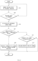
- FIG. 4 is a flowchart illustrating a method for controlling the intensity of a signal radiated, according to the invention.
- the processor 360 senses the folding state of the foldable housing 200 by using the sensor 340.
- the processor 360 senses the type of the folding state of the foldable housing 200 by using the sensor 340.
- the folding state includes a first state that the foldable housing 200 is folded and a second state that the foldable housing 200 is unfolded.
- the folding state may further include at least one third state which is intermediate between the first state that the foldable housing 200 is folded and the second state that the foldable housing 200 is unfolded.
- the third state may be the intermediate state described above.
- the folding state may include a plurality of third states.
- the plurality of third states may include a state that the angle formed between the first surface 250 of the first housing structure 210 and the third surface 260 of the second housing structure 220 is in the range of 0 to 30 degrees, 30 to 60 degrees, 60 to 90 degrees, 90 to 120 degrees, 120 to 150 degrees, and 150 to 180 degrees.
- the processor 360 calculates a reference capacitance for measuring the variation in the capacitance measured through the grip sensor circuitry 330 in operation 405.
- the reference capacitance is an average value of capacitances measured through the grip sensor circuitry 330 for a preset time, after the folding state of the foldable housing 200 is changed.
- the processor 360 determines whether the variation in the capacitance, which is measured through the grip sensor circuitry 330, exceeds a specific threshold value.
- the variation in the capacitance is a value obtained by subtracting the reference capacitance from the capacitance measured through the grip sensor circuitry 330.
- the measured capacitance is increased and the variation in the capacitance is increased.
- a preset threshold value may be varied depending on the folding state of the foldable housing 200.
- the threshold value when the folding state of the foldable housing 200 is sensed as the first state may be less than the threshold value when the folding state of the foldable housing 200 is sensed as the second state.
- the processor 360 may reduce the intensity of a signal radiated from the antenna radiator 310.
- the processor 360 may not reduce the intensity of the signal radiated through the antenna radiator 310.
- the processor 360 controls the wireless communication circuitry 320 to restrict the intensity of the signal radiated from the antenna radiator 310 to be equal to or less than a value resulting from the folding state of the foldable housing 200 in operation 409.
- the value resulting from the first state may be greater than the value resulting from the second state.
- the intensity of the signal radiated from the antenna radiator 310 may have a greater value, when the variation in the capacitance of the foldable housing 200 in the folded state exceeds the threshold value, as compared to when the variation in the capacitance of the foldable housing 200 in the unfolded state exceeds the threshold value.
- the value resulting from the third state may be less than the value resulting from the first state and may be greater than the value resulting from the second state.
- the intensity of a signal radiated from the antenna radiator 310 when the foldable housing 200 is in the intermediate state and the variation in the capacitance exceeds the threshold value may be less than the intensity of a signal radiated from the antenna radiator 310 when the foldable housing 200 is in the folded state and when the variation in the capacitance exceeds the threshold value, and may be greater than the intensity of a signal radiated from the antenna radiator 310 when the foldable housing 200 is in the unfolded state and when the variation in the capacitance exceeds the threshold value.
- a value from the plurality of third states may be reduced as the folding state approximates to the second state.
- the processor 360 may control the wireless communication circuitry 320 to restrict the intensity of the signal radiated from the antenna radiator 310 to be equal to or less than a value resulting from the folding state of the foldable housing 200 in operation 411.
- the processor 360 may release the restriction of the intensity of the signal radiated from the antenna radiator 310 in operation 413.
- the processor 360 may recover the intensity of the signal radiated from the antenna radiator 310.
- the processor 360 may calculate a reference capacitance when the folding state of the foldable housing 200 is changed (operation 403) and when the wireless communication circuitry 320 is controlled to restrict the intensity of the signal radiated from the antenna radiator 310 to be equal to or less than the value resulting from the folding state of the foldable housing 200 (operation 411).
- the processor 360 may release the restriction.
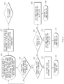
- FIG. 5 is a flowchart illustrating a method for controlling the intensity of a radiated signal through various manners by an electronic device 101, according a non-claimed example.
- the electronic device 101 may determine whether the value of a hall integrated circuit (hall IC) is changed in operation 510.
- the hall IC value may be a digital value indicating the folding state of the foldable housing 200.
- the hall IC value may be calculated based on a measurement result of the sensor 340 implemented with a hall sensor.
- the hall IC value may have a value of '0' or '1'.
- the hall IC value when the foldable housing 200 is in the unfolded state, the hall IC value may be '0'.
- the hall IC value when the foldable housing 200 is in the folded state, the hall IC value may be '1'.
- the electronic device 101 may determine the folding state of the electronic device as being changed.
- the electronic device 101 may refresh the grip sensor circuitry 330 and reset sensor data of the sensor 340 in operation 520.
- the capacitance measured by the grip sensor circuitry 330 is changed. Accordingly, the value measured before the folding state is changed may be removed.
- the electronic device 101 may recalculate a proximity offset value of the grip sensor circuitry 330.
- the electronic device 101 may measure a proximity average value.
- the electronic device 101 may set a threshold value based on the changed hall IC value in operation 520.
- the threshold value may be a value for changing the capacitance as much as possible in each folding state of the foldable housing 200.
- the electronic device 101 may calculate the variation in the capacitance measured by the grip sensor circuitry 330 and compare the variation with the threshold value in operation 530.
- the variation in the capacitance, which is measured by the grip sensor circuitry 330, is a difference value between an effective capacitance and an average capacitance.
- the electronic device 101 may set a proximity state to a working state when the variation in the capacitance measured by the grip sensor circuitry 330 is greater than the threshold value in operation 530, and may set the proximity state to a release state when the variation in the capacitance is less than or equal to the threshold value.
- the electronic device 101 may determine whether the proximity state is changed in operation 540. When the proximity state is changed, the electronic device 101 may proceed to operation 550. When the proximity state is not changed, the electronic device 101 may return to operation 530.
- the electronic device 101 may determine whether the changed proximity state is the working state in operation 550. When that the variation in the capacitance is changed to a value in the working state, which is greater than the threshold value, the electronic device 101 may proceed to operation 565. When the variation in the capacitance is not changed to a value in the working state, the electronic device 101 may proceed to operation 555.
- the electronic device 101 may set the communication processor (e.g., the auxiliary processor 123 of FIG. 1 ) to output a power value, which is recovered from the communication processor, through a power amplifier (PA), in operation 555.
- the communication processor e.g., the auxiliary processor 123 of FIG. 1
- PA power amplifier
- the electronic device 101 may control the output power to return to a normal sate, in operation 560.
- the electronic device 101 may recover the output power by performing "power back off'. Accordingly, when the variation in the capacitance is less than or equal to the threshold value, the electronic device 101 may maintain the normal output.
- the electronic device 101 may determine whether a present hall IC value is 1 in operation 565. The electronic device 101 may proceed to operation 570 when the present hall IC value is '1'. The electronic device may proceed to operation 580 when the present hall IC value is not '1'.
- the electronic device 101 may set the communication processor to output, through the PA, a power value, which is set to "power back off' in the communication processor.
- the "power back off' is set in the state that the foldable housing 200 is in a folder close (F/C) state or the folded state, in operation 570.
- the electronic device 101 may perform power back off in the F/C state in operation 575.
- the electronic device may restrict the maximum intensity of the signal radiated from the electronic device to a value corresponding to the threshold value set in the F/C state.
- the electronic device 101 may set the communication processor to output, through the PA, a power value set to "power back off", in the state that the foldable housing 200 is in a folder open (F/O) state, which is the unfolded state, in operation 580.
- a power value set to "power back off” in the state that the foldable housing 200 is in a folder open (F/O) state, which is the unfolded state, in operation 580.
- the electronic device 101 may perform power back off in the F/O state in operation 585.
- the electronic device 101 may restrict the maximum intensity of the signal radiated from the electronic device to a value corresponding to the threshold value set in the F/O state.
- the electronic device may be one of various types of electronic devices.
- the electronic devices may include, for example, a portable communication device (e.g., a smartphone), a computer device, a portable multimedia device, a portable medical device, a camera, a wearable device, or a home appliance. According to an embodiment of the disclosure, the electronic devices are not limited to those described above.
- module may include a unit implemented in hardware, software, or firmware, and may interchangeably be used with other terms, for example, “logic,” “logic block,” “part,” or “circuitry”.
- a module may be a single integral component, or a minimum unit or part thereof, adapted to perform one or more functions.
- the module may be implemented in a form of an application-specific integrated circuit (ASIC).
- ASIC application-specific integrated circuit
- Various embodiments as set forth herein may be implemented as software (e.g., the program 140) including one or more instructions that are stored in a storage medium (e.g., internal memory 136 or external memory 138) that is readable by a machine (e.g., the electronic device 101).
- a processor e.g., the processor 120 of the machine (e.g., the electronic device 101) may invoke at least one of the one or more instructions stored in the storage medium, and execute it, with or without using one or more other components under the control of the processor. This allows the machine to be operated to perform at least one function according to the at least one instruction invoked.
- the one or more instructions may include a code generated by a complier or a code executable by an interpreter.
- the machine-readable storage medium may be provided in the form of a non-transitory storage medium.
- non-transitory simply means that the storage medium is a tangible device, and does not include a signal (e.g., an electromagnetic wave), but this term does not differentiate between where data is semi-permanently stored in the storage medium and where the data is temporarily stored in the storage medium.
- a method according to various embodiments of the disclosure may be included and provided in a computer program product.
- the computer program product may be traded as a product between a seller and a buyer.
- the computer program product may be distributed in the form of a machine-readable storage medium (e.g., compact disc read only memory (CD-ROM)), or be distributed (e.g., downloaded or uploaded) online via an application store (e.g., PlayStore TM ), or between two user devices (e.g., smart phones) directly. If distributed online, at least part of the computer program product may be temporarily generated or at least temporarily stored in the machine-readable storage medium, such as memory of the manufacturer's server, a server of the application store, or a relay server.
- CD-ROM compact disc read only memory
- an application store e.g., PlayStore TM
- two user devices e.g., smart phones
- Each component (e.g., a module or a program) of the above-described components may include a single entity or multiple entities.
- a plurality of components e.g., modules or programs
- the integrated component may still perform one or more functions of each of the plurality of components in the same or similar manner as they are performed by a corresponding one of the plurality of components before the integration.
- operations performed by the module, the program, or another component may be carried out sequentially, in parallel, repeatedly, heuristically.
- the malfunction when the intensity of the signal radiated from the antenna radiator is controlled by the grip sensor, and when the foldable housing is folded, the malfunction may be prevented and the threshold value and the control power value may be set to different values depending on when the foldable housing is closed or open.
Landscapes
- Engineering & Computer Science (AREA)
- Computer Hardware Design (AREA)
- Theoretical Computer Science (AREA)
- General Engineering & Computer Science (AREA)
- Physics & Mathematics (AREA)
- General Physics & Mathematics (AREA)
- Human Computer Interaction (AREA)
- Signal Processing (AREA)
- Computer Networks & Wireless Communication (AREA)
- Mathematical Physics (AREA)
- Electromagnetism (AREA)
- Telephone Set Structure (AREA)
- Telephone Function (AREA)
Claims (7)
- Elektronische Vorrichtung, die Folgendes umfasst:ein klappbares Gehäuse (200), das Folgendes enthält:eine Scharnierstruktur (230);eine erste Gehäusestruktur (210), die mit der Scharnierstruktur (230) gekoppelt ist und eine erste Oberfläche (250), die einer ersten Richtung zugewandt ist, sowie eine zweite Oberfläche (270), die einer der ersten Richtung entgegengesetzten zweiten Richtung zugewandt ist, umfasst;eine zweite Gehäusestruktur (220), die mit der Scharnierstruktur (230) gekoppelt ist und eine dritte Oberfläche (260), die einer dritten Richtung zugewandt ist, sowie eine vierte Oberfläche (270), die einer der dritten Richtung entgegengesetzten vierten Richtung zugewandt ist, umfasst, und die in Bezug auf die erste Gehäusestruktur (210) um die Scharnierstruktur (230) klappbar ist, wobei die erste Oberfläche (250) der dritten Oberfläche (260) zugewandt ist, wenn das klappbare Gehäuse (200) eingeklappt ist, und die erste Richtung die gleiche wie die dritte Richtung ist, wenn das klappbare Gehäuse (200) ausgeklappt ist;eine drahtlose Kommunikationsschaltung (320), die innerhalb der ersten Gehäusestruktur (210) oder der zweiten Gehäusestruktur (220) angeordnet ist;einen Antennenstrahler (310), der innerhalb der ersten Gehäusestruktur (210) oder der zweiten Gehäusestruktur (220) angeordnet ist oder durch mindestens eine Oberfläche der ersten Gehäusestruktur (210) oder der zweiten Gehäusestruktur (220) freigelegt ist und elektrisch mit der drahtlosen Kommunikationsschaltung (320) verbunden ist;einen Sensor (340), der innerhalb der ersten Gehäusestruktur (210) oder der zweiten Gehäusestruktur (220) angeordnet ist und dazu konfiguriert ist, einen Klappzustand des klappbaren Gehäuses (200) zu erfassen, wobei der Klappzustand einen ersten Zustand, in dem das klappbare Gehäuse (200) eingeklappt ist, und einen zweiten Zustand, in dem das klappbare Gehäuse (200) ausgeklappt ist, umfasst;eine Griffsensorschaltung (330), die innerhalb der ersten Gehäusestruktur (210) oder der zweiten Gehäusestruktur (220) angeordnet ist oder durch mindestens eine Oberfläche der ersten Gehäusestruktur (210) oder der zweiten Gehäusestruktur (220) freigelegt ist;einen Prozessor (360), der innerhalb der ersten Gehäusestruktur (210) oder der zweiten Gehäusestruktur (220) angeordnet ist und operativ mit der drahtlosen Kommunikationsschaltung (320), dem Sensor (340) und der Griffsensorschaltung (330) verbunden ist; undeinen Speicher (350), der operativ mit dem Prozessor (360) verbunden ist und Anweisungen speichert, die, wenn sie von dem Prozessor (360) ausgeführt werden, den Prozessor zu Folgendem veranlassen:
Erfassen (401) des Klappzustands des klappbaren Gehäuses unter Verwendung des Sensors (401); undals Reaktion auf das Erkennen, dass der Klappzustand geändert ist, den Prozessor ferner zu Folgendem veranlassen:Berechnen (405) einer Referenzkapazität zum Messen einer Variation einer Kapazität, die durch die Griffsensorschaltung (330) gemessen wird, wobei es sich bei der Referenzkapazität um einen Durchschnittswert von Kapazitäten handelt, die durch die Griffsensorschaltung (330) für eine voreingestellte Zeit gemessen werden, nachdem der Klappzustand des klappbaren Gehäuses (200) geändert wurde;Bestimmen (407) der Variation der durch die Griffsensorschaltung (330) gemessenen Kapazität durch Subtrahieren der Referenzkapazität von der durch die Griffsensorschaltung (330) gemessenen Kapazität; undbasierend darauf, dass die Variation der durch die Griffsensorschaltung (330) gemessenen Kapazität einen voreingestellten Schwellenwert überschreitet, Steuern (409) der drahtlosen Kommunikationsschaltung (320), um eine Intensität eines von dem Antennenstrahler (310) abgestrahlten Signals so zu drosseln, dass sie gleich oder kleiner als ein vordefinierter Signalintensitätswert ist, der dem Klappzustand des klappbaren Gehäuses (200) entspricht, wobei verschiedenen Klappzuständen des klappbarn Gehäuses (200) unterschiedliche vordefinierte Signalintensitätswerte zugeordnet sind. - Elektronische Vorrichtung nach Anspruch 1, wobei der vordefinierte Signalintensitätswert, der dem ersten Zustand zugeordnet ist, größer ist als ein vordefinierter Signalintensitätswert, der sich aus dem zweiten Zustand ergibt.
- Elektronische Vorrichtung nach Anspruch 1, wobei:der Klappzustand einen dritten Zustand zwischen dem ersten Zustand, in dem das klappbare Gehäuse (200) eingeklappt ist, und dem zweiten Zustand, in dem das klappbare Gehäuse (200) ausgeklappt ist, umfasst, undein dem dritten Zustand zugeordneter vordefinierter Signalintensitätswert kleiner als der dem ersten Zustand zugeordnete vordefinierte Signalintensitätswert und größer als der dem zweiten Zustand zugeordnete vordefinierte Signalintensitätswert ist.
- Elektronische Vorrichtung nach Anspruch 3, wobei:der Klappzustand eine Vielzahl von dritten Zuständen enthält, undvordefinierte Signalintensitätswerte, die der Vielzahl von dritten Zuständen zugeordnet sind, abnehmen, wenn sich der Klappzustand dem zweiten Zustand annähert.
- Elektronische Vorrichtung nach Anspruch 1, wobei:der voreingestellte Schwellenwert in Abhängigkeit des Klappzustands des klappbaren Gehäuses (200) variiert; undein dem ersten Zustand zugeordneter Schwellenwert kleiner als ein dem zweiten Zustand zugeordneter Schwellenwert ist.
- Elektronische Vorrichtung nach Anspruch 1, wobei der Speicher Anweisungen speichert, die, wenn sie von dem Prozessor ausgeführt werden, den Prozessor zu Folgendem veranlassen: Aufheben (413) der Drosselung der Intensität des von dem Antennenstrahler (310) abgestrahlten Signals, basierend darauf, dass die Variation der durch die Griffsensorschaltung (330) gemessenen Kapazität den voreingestellten Schwellenwert nicht überschreitet.
- Elektronische Vorrichtung nach Anspruch 1, wobei der voreingestellte Schwellenwert kleiner ist, wenn sich das klappbare Gehäuse im eingeklappten Zustand befindet, als wenn sich das klappbare Gehäuse im ausgeklappten Zustand befindet.
Applications Claiming Priority (1)
| Application Number | Priority Date | Filing Date | Title |
|---|---|---|---|
| KR1020180132604A KR102516485B1 (ko) | 2018-10-31 | 2018-10-31 | 폴더블 하우징을 포함하는 전자 장치 |
Publications (3)
| Publication Number | Publication Date |
|---|---|
| EP3671948A2 EP3671948A2 (de) | 2020-06-24 |
| EP3671948A3 EP3671948A3 (de) | 2020-10-21 |
| EP3671948B1 true EP3671948B1 (de) | 2023-05-10 |
Family
ID=68387148
Family Applications (1)
| Application Number | Title | Priority Date | Filing Date |
|---|---|---|---|
| EP19205700.8A Active EP3671948B1 (de) | 2018-10-31 | 2019-10-28 | Faltbare elektronische vorrichtung mit kontrollierter antennensignalstärke |
Country Status (4)
| Country | Link |
|---|---|
| US (1) | US11201635B2 (de) |
| EP (1) | EP3671948B1 (de) |
| KR (1) | KR102516485B1 (de) |
| CN (1) | CN111124040B (de) |
Families Citing this family (27)
| Publication number | Priority date | Publication date | Assignee | Title |
|---|---|---|---|---|
| WO2020032620A1 (en) * | 2018-08-10 | 2020-02-13 | Samsung Electronics Co., Ltd. | Foldable electronic device including antenna |
| KR102524236B1 (ko) * | 2018-11-16 | 2023-04-24 | 삼성전자주식회사 | 방수 구조를 포함하는 전자 장치 |
| US11917298B2 (en) * | 2020-02-03 | 2024-02-27 | Sony Semiconductor Solutions Corporation | Electronic device |
| KR102866896B1 (ko) * | 2020-07-13 | 2025-10-01 | 삼성전자주식회사 | 전자 장치 및 전력 제어 방법 |
| KR20220013786A (ko) * | 2020-07-27 | 2022-02-04 | 삼성전자주식회사 | 그립 센서를 포함하는 전자 장치에서 디스플레이의 확장 여부에 따라 전송 전력을 조절하는 장치 및 방법 |
| KR102902132B1 (ko) | 2020-09-04 | 2025-12-19 | 삼성전자 주식회사 | 커패시턴스 센서를 포함하는 전자 장치 |
| US11895253B2 (en) * | 2021-03-04 | 2024-02-06 | Samsung Electronics Co., Ltd. | Antenna structure and electronic device including the same |
| KR102886799B1 (ko) * | 2021-03-08 | 2025-11-18 | 삼성전자주식회사 | 전자 장치 및 형태 변경이 가능한 전자 장치에서 송신 신호의 전력을 제어하는 방법 |
| CN116982264A (zh) | 2021-03-08 | 2023-10-31 | 三星电子株式会社 | 电子装置和用于控制可变形电子装置中的发射信号的功率的方法 |
| KR102880834B1 (ko) * | 2021-03-22 | 2025-11-05 | 삼성전자 주식회사 | 그립 센서를 포함하는 전자 장치 및 그의 동작 방법 |
| KR102845136B1 (ko) | 2021-04-22 | 2025-08-12 | 삼성전자주식회사 | 방사 성능 향상을 위한 안테나 구조 및 이를 포함하는 전자 장치 |
| US12081292B2 (en) | 2021-07-19 | 2024-09-03 | Samsung Electronics Co., Ltd. | Electronic device including antenna and operating method thereof |
| KR20230013509A (ko) * | 2021-07-19 | 2023-01-26 | 삼성전자주식회사 | 안테나를 포함하는 전자 장치 및 그의 동작 방법 |
| EP4358293B1 (de) | 2021-08-09 | 2025-10-08 | Samsung Electronics Co., Ltd. | Elektronische vorrichtung mit antenne |
| KR20230022498A (ko) * | 2021-08-09 | 2023-02-16 | 삼성전자주식회사 | 안테나를 포함하는 전자 장치 |
| EP4339733A4 (de) * | 2021-08-10 | 2024-08-21 | Samsung Electronics Co., Ltd. | Faltbare elektronische vorrichtung |
| CN115915372A (zh) * | 2021-08-16 | 2023-04-04 | 荣耀终端有限公司 | 功率管理方法、终端及存储介质 |
| CN113905433A (zh) * | 2021-09-29 | 2022-01-07 | Oppo广东移动通信有限公司 | 天线模组控制方法及相关装置 |
| EP4386977A4 (de) * | 2021-10-24 | 2024-12-11 | Samsung Electronics Co., Ltd. | Elektronische vorrichtung und verfahren zur identifizierung des greifzustands einer elektronischen vorrichtung |
| WO2023085753A1 (ko) * | 2021-11-10 | 2023-05-19 | 삼성전자 주식회사 | 플렉서블 디스플레이를 포함하는 전자 장치 및 그 동작 방법 |
| WO2023214659A1 (ko) * | 2022-05-06 | 2023-11-09 | 삼성전자 주식회사 | 그립 센서를 포함하는 전자 장치 및 방법 |
| US12445973B2 (en) | 2022-06-14 | 2025-10-14 | Samsung Electronics Co., Ltd. | Electronic device for adjusting parameter for driving of grip sensor and method thereof |
| WO2023243810A1 (ko) * | 2022-06-14 | 2023-12-21 | 삼성전자 주식회사 | 그립 센서의 구동을 위한 파라미터를 조절하기 위한 전자 장치 및 그 방법 |
| CN115190195A (zh) * | 2022-06-27 | 2022-10-14 | 联想(北京)有限公司 | 一种控制方法及电子设备 |
| EP4503464A4 (de) * | 2022-08-09 | 2025-11-26 | Samsung Electronics Co Ltd | Elektronische vorrichtung zum wechseln einer übertragungsantenne und verfahren zum betrieb davon |
| WO2024225540A1 (ko) * | 2023-04-25 | 2024-10-31 | 삼성전자 주식회사 | 그립을 감지하는 전자 장치 및 제어 방법 |
| US20250231679A1 (en) * | 2024-01-12 | 2025-07-17 | Huawei Technologies Co., Ltd. | Adjacent capacitive touch screen event tracking |
Family Cites Families (9)
| Publication number | Priority date | Publication date | Assignee | Title |
|---|---|---|---|---|
| KR101866272B1 (ko) | 2011-12-15 | 2018-06-12 | 삼성전자주식회사 | 그립 센서를 이용한 사용자 기반의 휴대용 단말기의 장치 및 방법 |
| KR20160030732A (ko) * | 2014-09-11 | 2016-03-21 | 삼성전자주식회사 | 보호 커버의 개폐 상태를 판단하기 위한 방법 및 그 전자 장치 |
| US10244488B2 (en) * | 2014-09-27 | 2019-03-26 | Intel Corporation | Body presence sensor calibration |
| US9552020B2 (en) * | 2014-11-26 | 2017-01-24 | Kabushiki Kaisha Toshiba | Electronic apparatus |
| KR20170067548A (ko) * | 2015-12-08 | 2017-06-16 | 삼성전자주식회사 | 전자 장치 및 그의 출력 전력 백 오프 제어 방법 |
| WO2017101987A1 (en) | 2015-12-15 | 2017-06-22 | REG Life Sciences, LLC | Omega-hydroxylase-related fusion polypeptide variants with improved properties |
| US10013038B2 (en) * | 2016-01-05 | 2018-07-03 | Microsoft Technology Licensing, Llc | Dynamic antenna power control for multi-context device |
| KR102499448B1 (ko) * | 2016-07-21 | 2023-02-15 | 삼성전자주식회사 | 힌지 구조를 포함하는 전자 장치 |
| US20190064950A1 (en) * | 2017-08-24 | 2019-02-28 | Int Tech Co., Ltd. | Foldable electronic device and control method thereof |
-
2018
- 2018-10-31 KR KR1020180132604A patent/KR102516485B1/ko active Active
-
2019
- 2019-10-22 CN CN201911004926.7A patent/CN111124040B/zh active Active
- 2019-10-28 EP EP19205700.8A patent/EP3671948B1/de active Active
- 2019-10-30 US US16/669,164 patent/US11201635B2/en active Active
Also Published As
| Publication number | Publication date |
|---|---|
| US20200136668A1 (en) | 2020-04-30 |
| KR102516485B1 (ko) | 2023-04-03 |
| KR20200049391A (ko) | 2020-05-08 |
| CN111124040A (zh) | 2020-05-08 |
| EP3671948A3 (de) | 2020-10-21 |
| CN111124040B (zh) | 2024-04-26 |
| US11201635B2 (en) | 2021-12-14 |
| EP3671948A2 (de) | 2020-06-24 |
Similar Documents
| Publication | Publication Date | Title |
|---|---|---|
| EP3671948B1 (de) | Faltbare elektronische vorrichtung mit kontrollierter antennensignalstärke | |
| US12133177B2 (en) | Electronic device and method for controlling transmission power thereof | |
| EP3948832B1 (de) | Faltbare elektronische vorrichtung zur erfassung des faltwinkels und betriebsverfahren dafür | |
| US11392247B2 (en) | Foldable electronic device and method for detecting touch input in foldable electronic device | |
| US11470190B2 (en) | Electronic device having grip sensor and method of controlling the electronic device having grip sensor | |
| US20200333836A1 (en) | Foldable electronic device | |
| US11310354B2 (en) | Foldable device and controlling method thereof | |
| US20200218310A1 (en) | Method for controlling power back off using grip sensor and electronic device for supporting the same | |
| US20210174766A1 (en) | Electronic device for controlling divided screen | |
| EP3672089B1 (de) | Verfahren zur durchführung einer kommunikation mit einer externen elektronischen vorrichtung unter verwendung einer resonanzfrequenz, die in abhängigkeit von der nähe des externen objekts modifiziert ist, und elektronische vorrichtung zur unterstützung davon | |
| US20250217091A1 (en) | Electronic device and method for controlling screen displayed on flexible display | |
| US11843400B2 (en) | Electronic device for controlling output of antenna by using APC of communication module, and method for operation of electronic device | |
| US11888508B2 (en) | Signal processing circuit and electronic device comprising same | |
| US11415662B2 (en) | Electronic device for detecting location of user and method thereof | |
| US11552431B2 (en) | Input/output terminal and electronic device comprising same | |
| US11392222B2 (en) | Electronic device, and method for controlling external electronic device on basis of usage state of electronic device | |
| EP4418006A1 (de) | Signalsteuerungsverfahren und wearable-vorrichtung zur unterstützung davon | |
| US11476895B2 (en) | External device including at least one antenna, and electronic device and method for improving antenna performance using same |
Legal Events
| Date | Code | Title | Description |
|---|---|---|---|
| PUAI | Public reference made under article 153(3) epc to a published international application that has entered the european phase |
Free format text: ORIGINAL CODE: 0009012 |
|
| STAA | Information on the status of an ep patent application or granted ep patent |
Free format text: STATUS: THE APPLICATION HAS BEEN PUBLISHED |
|
| AK | Designated contracting states |
Kind code of ref document: A2 Designated state(s): AL AT BE BG CH CY CZ DE DK EE ES FI FR GB GR HR HU IE IS IT LI LT LU LV MC MK MT NL NO PL PT RO RS SE SI SK SM TR |
|
| AX | Request for extension of the european patent |
Extension state: BA ME |
|
| PUAL | Search report despatched |
Free format text: ORIGINAL CODE: 0009013 |
|
| AK | Designated contracting states |
Kind code of ref document: A3 Designated state(s): AL AT BE BG CH CY CZ DE DK EE ES FI FR GB GR HR HU IE IS IT LI LT LU LV MC MK MT NL NO PL PT RO RS SE SI SK SM TR |
|
| AX | Request for extension of the european patent |
Extension state: BA ME |
|
| RIC1 | Information provided on ipc code assigned before grant |
Ipc: G06F 1/16 20060101ALI20200914BHEP Ipc: H04B 1/3827 20150101ALI20200914BHEP Ipc: H04W 52/30 20090101ALI20200914BHEP Ipc: H01Q 1/24 20060101AFI20200914BHEP |
|
| STAA | Information on the status of an ep patent application or granted ep patent |
Free format text: STATUS: REQUEST FOR EXAMINATION WAS MADE |
|
| 17P | Request for examination filed |
Effective date: 20210118 |
|
| RBV | Designated contracting states (corrected) |
Designated state(s): AL AT BE BG CH CY CZ DE DK EE ES FI FR GB GR HR HU IE IS IT LI LT LU LV MC MK MT NL NO PL PT RO RS SE SI SK SM TR |
|
| STAA | Information on the status of an ep patent application or granted ep patent |
Free format text: STATUS: EXAMINATION IS IN PROGRESS |
|
| 17Q | First examination report despatched |
Effective date: 20211124 |
|
| GRAP | Despatch of communication of intention to grant a patent |
Free format text: ORIGINAL CODE: EPIDOSNIGR1 |
|
| STAA | Information on the status of an ep patent application or granted ep patent |
Free format text: STATUS: GRANT OF PATENT IS INTENDED |
|
| INTG | Intention to grant announced |
Effective date: 20230228 |
|
| GRAS | Grant fee paid |
Free format text: ORIGINAL CODE: EPIDOSNIGR3 |
|
| GRAA | (expected) grant |
Free format text: ORIGINAL CODE: 0009210 |
|
| STAA | Information on the status of an ep patent application or granted ep patent |
Free format text: STATUS: THE PATENT HAS BEEN GRANTED |
|
| AK | Designated contracting states |
Kind code of ref document: B1 Designated state(s): AL AT BE BG CH CY CZ DE DK EE ES FI FR GB GR HR HU IE IS IT LI LT LU LV MC MK MT NL NO PL PT RO RS SE SI SK SM TR |
|
| REG | Reference to a national code |
Ref country code: GB Ref legal event code: FG4D |
|
| REG | Reference to a national code |
Ref country code: AT Ref legal event code: REF Ref document number: 1567644 Country of ref document: AT Kind code of ref document: T Effective date: 20230515 Ref country code: CH Ref legal event code: EP |
|
| REG | Reference to a national code |
Ref country code: DE Ref legal event code: R096 Ref document number: 602019028655 Country of ref document: DE |
|
| REG | Reference to a national code |
Ref country code: IE Ref legal event code: FG4D |
|
| REG | Reference to a national code |
Ref country code: LT Ref legal event code: MG9D |
|
| REG | Reference to a national code |
Ref country code: NL Ref legal event code: MP Effective date: 20230510 |
|
| REG | Reference to a national code |
Ref country code: AT Ref legal event code: MK05 Ref document number: 1567644 Country of ref document: AT Kind code of ref document: T Effective date: 20230510 |
|
| PG25 | Lapsed in a contracting state [announced via postgrant information from national office to epo] |
Ref country code: SE Free format text: LAPSE BECAUSE OF FAILURE TO SUBMIT A TRANSLATION OF THE DESCRIPTION OR TO PAY THE FEE WITHIN THE PRESCRIBED TIME-LIMIT Effective date: 20230510 Ref country code: PT Free format text: LAPSE BECAUSE OF FAILURE TO SUBMIT A TRANSLATION OF THE DESCRIPTION OR TO PAY THE FEE WITHIN THE PRESCRIBED TIME-LIMIT Effective date: 20230911 Ref country code: NO Free format text: LAPSE BECAUSE OF FAILURE TO SUBMIT A TRANSLATION OF THE DESCRIPTION OR TO PAY THE FEE WITHIN THE PRESCRIBED TIME-LIMIT Effective date: 20230810 Ref country code: NL Free format text: LAPSE BECAUSE OF FAILURE TO SUBMIT A TRANSLATION OF THE DESCRIPTION OR TO PAY THE FEE WITHIN THE PRESCRIBED TIME-LIMIT Effective date: 20230510 Ref country code: ES Free format text: LAPSE BECAUSE OF FAILURE TO SUBMIT A TRANSLATION OF THE DESCRIPTION OR TO PAY THE FEE WITHIN THE PRESCRIBED TIME-LIMIT Effective date: 20230510 Ref country code: AT Free format text: LAPSE BECAUSE OF FAILURE TO SUBMIT A TRANSLATION OF THE DESCRIPTION OR TO PAY THE FEE WITHIN THE PRESCRIBED TIME-LIMIT Effective date: 20230510 |
|
| PG25 | Lapsed in a contracting state [announced via postgrant information from national office to epo] |
Ref country code: RS Free format text: LAPSE BECAUSE OF FAILURE TO SUBMIT A TRANSLATION OF THE DESCRIPTION OR TO PAY THE FEE WITHIN THE PRESCRIBED TIME-LIMIT Effective date: 20230510 Ref country code: PL Free format text: LAPSE BECAUSE OF FAILURE TO SUBMIT A TRANSLATION OF THE DESCRIPTION OR TO PAY THE FEE WITHIN THE PRESCRIBED TIME-LIMIT Effective date: 20230510 Ref country code: LV Free format text: LAPSE BECAUSE OF FAILURE TO SUBMIT A TRANSLATION OF THE DESCRIPTION OR TO PAY THE FEE WITHIN THE PRESCRIBED TIME-LIMIT Effective date: 20230510 Ref country code: LT Free format text: LAPSE BECAUSE OF FAILURE TO SUBMIT A TRANSLATION OF THE DESCRIPTION OR TO PAY THE FEE WITHIN THE PRESCRIBED TIME-LIMIT Effective date: 20230510 Ref country code: IS Free format text: LAPSE BECAUSE OF FAILURE TO SUBMIT A TRANSLATION OF THE DESCRIPTION OR TO PAY THE FEE WITHIN THE PRESCRIBED TIME-LIMIT Effective date: 20230910 Ref country code: HR Free format text: LAPSE BECAUSE OF FAILURE TO SUBMIT A TRANSLATION OF THE DESCRIPTION OR TO PAY THE FEE WITHIN THE PRESCRIBED TIME-LIMIT Effective date: 20230510 Ref country code: GR Free format text: LAPSE BECAUSE OF FAILURE TO SUBMIT A TRANSLATION OF THE DESCRIPTION OR TO PAY THE FEE WITHIN THE PRESCRIBED TIME-LIMIT Effective date: 20230811 |
|
| PG25 | Lapsed in a contracting state [announced via postgrant information from national office to epo] |
Ref country code: FI Free format text: LAPSE BECAUSE OF FAILURE TO SUBMIT A TRANSLATION OF THE DESCRIPTION OR TO PAY THE FEE WITHIN THE PRESCRIBED TIME-LIMIT Effective date: 20230510 |
|
| PG25 | Lapsed in a contracting state [announced via postgrant information from national office to epo] |
Ref country code: SK Free format text: LAPSE BECAUSE OF FAILURE TO SUBMIT A TRANSLATION OF THE DESCRIPTION OR TO PAY THE FEE WITHIN THE PRESCRIBED TIME-LIMIT Effective date: 20230510 |
|
| PG25 | Lapsed in a contracting state [announced via postgrant information from national office to epo] |
Ref country code: SM Free format text: LAPSE BECAUSE OF FAILURE TO SUBMIT A TRANSLATION OF THE DESCRIPTION OR TO PAY THE FEE WITHIN THE PRESCRIBED TIME-LIMIT Effective date: 20230510 Ref country code: SK Free format text: LAPSE BECAUSE OF FAILURE TO SUBMIT A TRANSLATION OF THE DESCRIPTION OR TO PAY THE FEE WITHIN THE PRESCRIBED TIME-LIMIT Effective date: 20230510 Ref country code: RO Free format text: LAPSE BECAUSE OF FAILURE TO SUBMIT A TRANSLATION OF THE DESCRIPTION OR TO PAY THE FEE WITHIN THE PRESCRIBED TIME-LIMIT Effective date: 20230510 Ref country code: EE Free format text: LAPSE BECAUSE OF FAILURE TO SUBMIT A TRANSLATION OF THE DESCRIPTION OR TO PAY THE FEE WITHIN THE PRESCRIBED TIME-LIMIT Effective date: 20230510 Ref country code: DK Free format text: LAPSE BECAUSE OF FAILURE TO SUBMIT A TRANSLATION OF THE DESCRIPTION OR TO PAY THE FEE WITHIN THE PRESCRIBED TIME-LIMIT Effective date: 20230510 Ref country code: CZ Free format text: LAPSE BECAUSE OF FAILURE TO SUBMIT A TRANSLATION OF THE DESCRIPTION OR TO PAY THE FEE WITHIN THE PRESCRIBED TIME-LIMIT Effective date: 20230510 |
|
| REG | Reference to a national code |
Ref country code: DE Ref legal event code: R097 Ref document number: 602019028655 Country of ref document: DE |
|
| PLBE | No opposition filed within time limit |
Free format text: ORIGINAL CODE: 0009261 |
|
| STAA | Information on the status of an ep patent application or granted ep patent |
Free format text: STATUS: NO OPPOSITION FILED WITHIN TIME LIMIT |
|
| 26N | No opposition filed |
Effective date: 20240213 |
|
| PG25 | Lapsed in a contracting state [announced via postgrant information from national office to epo] |
Ref country code: SI Free format text: LAPSE BECAUSE OF FAILURE TO SUBMIT A TRANSLATION OF THE DESCRIPTION OR TO PAY THE FEE WITHIN THE PRESCRIBED TIME-LIMIT Effective date: 20230510 |
|
| PG25 | Lapsed in a contracting state [announced via postgrant information from national office to epo] |
Ref country code: SI Free format text: LAPSE BECAUSE OF FAILURE TO SUBMIT A TRANSLATION OF THE DESCRIPTION OR TO PAY THE FEE WITHIN THE PRESCRIBED TIME-LIMIT Effective date: 20230510 Ref country code: IT Free format text: LAPSE BECAUSE OF FAILURE TO SUBMIT A TRANSLATION OF THE DESCRIPTION OR TO PAY THE FEE WITHIN THE PRESCRIBED TIME-LIMIT Effective date: 20230510 Ref country code: MC Free format text: LAPSE BECAUSE OF FAILURE TO SUBMIT A TRANSLATION OF THE DESCRIPTION OR TO PAY THE FEE WITHIN THE PRESCRIBED TIME-LIMIT Effective date: 20230510 |
|
| REG | Reference to a national code |
Ref country code: CH Ref legal event code: PL |
|
| REG | Reference to a national code |
Ref country code: BE Ref legal event code: MM Effective date: 20231031 |
|
| PG25 | Lapsed in a contracting state [announced via postgrant information from national office to epo] |
Ref country code: LU Free format text: LAPSE BECAUSE OF NON-PAYMENT OF DUE FEES Effective date: 20231028 |
|
| PG25 | Lapsed in a contracting state [announced via postgrant information from national office to epo] |
Ref country code: LU Free format text: LAPSE BECAUSE OF NON-PAYMENT OF DUE FEES Effective date: 20231028 |
|
| PG25 | Lapsed in a contracting state [announced via postgrant information from national office to epo] |
Ref country code: CH Free format text: LAPSE BECAUSE OF NON-PAYMENT OF DUE FEES Effective date: 20231031 |
|
| PG25 | Lapsed in a contracting state [announced via postgrant information from national office to epo] |
Ref country code: FR Free format text: LAPSE BECAUSE OF NON-PAYMENT OF DUE FEES Effective date: 20231031 Ref country code: CH Free format text: LAPSE BECAUSE OF NON-PAYMENT OF DUE FEES Effective date: 20231031 |
|
| PG25 | Lapsed in a contracting state [announced via postgrant information from national office to epo] |
Ref country code: BE Free format text: LAPSE BECAUSE OF NON-PAYMENT OF DUE FEES Effective date: 20231031 |
|
| PG25 | Lapsed in a contracting state [announced via postgrant information from national office to epo] |
Ref country code: IE Free format text: LAPSE BECAUSE OF NON-PAYMENT OF DUE FEES Effective date: 20231028 |
|
| PG25 | Lapsed in a contracting state [announced via postgrant information from national office to epo] |
Ref country code: IE Free format text: LAPSE BECAUSE OF NON-PAYMENT OF DUE FEES Effective date: 20231028 |
|
| PG25 | Lapsed in a contracting state [announced via postgrant information from national office to epo] |
Ref country code: BG Free format text: LAPSE BECAUSE OF FAILURE TO SUBMIT A TRANSLATION OF THE DESCRIPTION OR TO PAY THE FEE WITHIN THE PRESCRIBED TIME-LIMIT Effective date: 20230510 |
|
| PG25 | Lapsed in a contracting state [announced via postgrant information from national office to epo] |
Ref country code: BG Free format text: LAPSE BECAUSE OF FAILURE TO SUBMIT A TRANSLATION OF THE DESCRIPTION OR TO PAY THE FEE WITHIN THE PRESCRIBED TIME-LIMIT Effective date: 20230510 |
|
| PG25 | Lapsed in a contracting state [announced via postgrant information from national office to epo] |
Ref country code: CY Free format text: LAPSE BECAUSE OF FAILURE TO SUBMIT A TRANSLATION OF THE DESCRIPTION OR TO PAY THE FEE WITHIN THE PRESCRIBED TIME-LIMIT; INVALID AB INITIO Effective date: 20191028 |
|
| PG25 | Lapsed in a contracting state [announced via postgrant information from national office to epo] |
Ref country code: HU Free format text: LAPSE BECAUSE OF FAILURE TO SUBMIT A TRANSLATION OF THE DESCRIPTION OR TO PAY THE FEE WITHIN THE PRESCRIBED TIME-LIMIT; INVALID AB INITIO Effective date: 20191028 |
|
| PGFP | Annual fee paid to national office [announced via postgrant information from national office to epo] |
Ref country code: GB Payment date: 20250922 Year of fee payment: 7 |
|
| PG25 | Lapsed in a contracting state [announced via postgrant information from national office to epo] |
Ref country code: TR Free format text: LAPSE BECAUSE OF FAILURE TO SUBMIT A TRANSLATION OF THE DESCRIPTION OR TO PAY THE FEE WITHIN THE PRESCRIBED TIME-LIMIT Effective date: 20230510 |
|
| PGFP | Annual fee paid to national office [announced via postgrant information from national office to epo] |
Ref country code: DE Payment date: 20250922 Year of fee payment: 7 |