EP3671801A1 - Abgedichtetes batteriesicherungsmodul mit energieableitkappe - Google Patents
Abgedichtetes batteriesicherungsmodul mit energieableitkappe Download PDFInfo
- Publication number
- EP3671801A1 EP3671801A1 EP19212596.1A EP19212596A EP3671801A1 EP 3671801 A1 EP3671801 A1 EP 3671801A1 EP 19212596 A EP19212596 A EP 19212596A EP 3671801 A1 EP3671801 A1 EP 3671801A1
- Authority
- EP
- European Patent Office
- Prior art keywords
- fuse
- mounting block
- main body
- body portion
- hole
- Prior art date
- Legal status (The legal status is an assumption and is not a legal conclusion. Google has not performed a legal analysis and makes no representation as to the accuracy of the status listed.)
- Granted
Links
Images



Classifications
-
- H—ELECTRICITY
- H01—ELECTRIC ELEMENTS
- H01H—ELECTRIC SWITCHES; RELAYS; SELECTORS; EMERGENCY PROTECTIVE DEVICES
- H01H85/00—Protective devices in which the current flows through a part of fusible material and this current is interrupted by displacement of the fusible material when this current becomes excessive
- H01H85/0013—Means for preventing damage, e.g. by ambient influences to the fuse
-
- H—ELECTRICITY
- H01—ELECTRIC ELEMENTS
- H01M—PROCESSES OR MEANS, e.g. BATTERIES, FOR THE DIRECT CONVERSION OF CHEMICAL ENERGY INTO ELECTRICAL ENERGY
- H01M50/00—Constructional details or processes of manufacture of the non-active parts of electrochemical cells other than fuel cells, e.g. hybrid cells
- H01M50/50—Current conducting connections for cells or batteries
- H01M50/572—Means for preventing undesired use or discharge
- H01M50/574—Devices or arrangements for the interruption of current
- H01M50/581—Devices or arrangements for the interruption of current in response to temperature
-
- H—ELECTRICITY
- H01—ELECTRIC ELEMENTS
- H01H—ELECTRIC SWITCHES; RELAYS; SELECTORS; EMERGENCY PROTECTIVE DEVICES
- H01H85/00—Protective devices in which the current flows through a part of fusible material and this current is interrupted by displacement of the fusible material when this current becomes excessive
- H01H85/0013—Means for preventing damage, e.g. by ambient influences to the fuse
- H01H85/0021—Means for preventing damage, e.g. by ambient influences to the fuse water or dustproof devices
- H01H85/003—Means for preventing damage, e.g. by ambient influences to the fuse water or dustproof devices casings for the fusible element
-
- H—ELECTRICITY
- H01—ELECTRIC ELEMENTS
- H01H—ELECTRIC SWITCHES; RELAYS; SELECTORS; EMERGENCY PROTECTIVE DEVICES
- H01H85/00—Protective devices in which the current flows through a part of fusible material and this current is interrupted by displacement of the fusible material when this current becomes excessive
- H01H85/02—Details
- H01H85/04—Fuses, i.e. expendable parts of the protective device, e.g. cartridges
- H01H85/05—Component parts thereof
- H01H85/143—Electrical contacts; Fastening fusible members to such contacts
-
- H—ELECTRICITY
- H01—ELECTRIC ELEMENTS
- H01H—ELECTRIC SWITCHES; RELAYS; SELECTORS; EMERGENCY PROTECTIVE DEVICES
- H01H85/00—Protective devices in which the current flows through a part of fusible material and this current is interrupted by displacement of the fusible material when this current becomes excessive
- H01H85/02—Details
- H01H85/04—Fuses, i.e. expendable parts of the protective device, e.g. cartridges
- H01H85/05—Component parts thereof
- H01H85/165—Casings
-
- H—ELECTRICITY
- H01—ELECTRIC ELEMENTS
- H01H—ELECTRIC SWITCHES; RELAYS; SELECTORS; EMERGENCY PROTECTIVE DEVICES
- H01H85/00—Protective devices in which the current flows through a part of fusible material and this current is interrupted by displacement of the fusible material when this current becomes excessive
- H01H85/02—Details
- H01H85/04—Fuses, i.e. expendable parts of the protective device, e.g. cartridges
- H01H85/05—Component parts thereof
- H01H85/165—Casings
- H01H85/175—Casings characterised by the casing shape or form
-
- H—ELECTRICITY
- H01—ELECTRIC ELEMENTS
- H01H—ELECTRIC SWITCHES; RELAYS; SELECTORS; EMERGENCY PROTECTIVE DEVICES
- H01H85/00—Protective devices in which the current flows through a part of fusible material and this current is interrupted by displacement of the fusible material when this current becomes excessive
- H01H85/02—Details
- H01H85/20—Bases for supporting the fuse; Separate parts thereof
-
- H—ELECTRICITY
- H01—ELECTRIC ELEMENTS
- H01H—ELECTRIC SWITCHES; RELAYS; SELECTORS; EMERGENCY PROTECTIVE DEVICES
- H01H85/00—Protective devices in which the current flows through a part of fusible material and this current is interrupted by displacement of the fusible material when this current becomes excessive
- H01H85/02—Details
- H01H85/43—Means for exhausting or absorbing gases liberated by fusing arc, or for ventilating excess pressure generated by heating
-
- H—ELECTRICITY
- H01—ELECTRIC ELEMENTS
- H01M—PROCESSES OR MEANS, e.g. BATTERIES, FOR THE DIRECT CONVERSION OF CHEMICAL ENERGY INTO ELECTRICAL ENERGY
- H01M50/00—Constructional details or processes of manufacture of the non-active parts of electrochemical cells other than fuel cells, e.g. hybrid cells
- H01M50/50—Current conducting connections for cells or batteries
- H01M50/572—Means for preventing undesired use or discharge
-
- H—ELECTRICITY
- H02—GENERATION; CONVERSION OR DISTRIBUTION OF ELECTRIC POWER
- H02H—EMERGENCY PROTECTIVE CIRCUIT ARRANGEMENTS
- H02H7/00—Emergency protective circuit arrangements specially adapted for specific types of electric machines or apparatus or for sectionalised protection of cable or line systems, and effecting automatic switching in the event of an undesired change from normal working conditions
- H02H7/18—Emergency protective circuit arrangements specially adapted for specific types of electric machines or apparatus or for sectionalised protection of cable or line systems, and effecting automatic switching in the event of an undesired change from normal working conditions for batteries; for accumulators
-
- H—ELECTRICITY
- H01—ELECTRIC ELEMENTS
- H01H—ELECTRIC SWITCHES; RELAYS; SELECTORS; EMERGENCY PROTECTIVE DEVICES
- H01H85/00—Protective devices in which the current flows through a part of fusible material and this current is interrupted by displacement of the fusible material when this current becomes excessive
- H01H85/02—Details
- H01H85/0241—Structural association of a fuse and another component or apparatus
- H01H2085/025—Structural association with a binding post of a storage battery
-
- H—ELECTRICITY
- H01—ELECTRIC ELEMENTS
- H01H—ELECTRIC SWITCHES; RELAYS; SELECTORS; EMERGENCY PROTECTIVE DEVICES
- H01H85/00—Protective devices in which the current flows through a part of fusible material and this current is interrupted by displacement of the fusible material when this current becomes excessive
- H01H85/02—Details
- H01H85/38—Means for extinguishing or suppressing arc
- H01H2085/383—Means for extinguishing or suppressing arc with insulating stationary parts
-
- H—ELECTRICITY
- H01—ELECTRIC ELEMENTS
- H01H—ELECTRIC SWITCHES; RELAYS; SELECTORS; EMERGENCY PROTECTIVE DEVICES
- H01H85/00—Protective devices in which the current flows through a part of fusible material and this current is interrupted by displacement of the fusible material when this current becomes excessive
- H01H85/02—Details
- H01H85/04—Fuses, i.e. expendable parts of the protective device, e.g. cartridges
- H01H85/05—Component parts thereof
- H01H85/055—Fusible members
- H01H85/08—Fusible members characterised by the shape or form of the fusible member
- H01H85/10—Fusible members characterised by the shape or form of the fusible member with constriction for localised fusing
-
- H—ELECTRICITY
- H01—ELECTRIC ELEMENTS
- H01M—PROCESSES OR MEANS, e.g. BATTERIES, FOR THE DIRECT CONVERSION OF CHEMICAL ENERGY INTO ELECTRICAL ENERGY
- H01M2200/00—Safety devices for primary or secondary batteries
- H01M2200/10—Temperature sensitive devices
- H01M2200/103—Fuse
-
- H—ELECTRICITY
- H01—ELECTRIC ELEMENTS
- H01M—PROCESSES OR MEANS, e.g. BATTERIES, FOR THE DIRECT CONVERSION OF CHEMICAL ENERGY INTO ELECTRICAL ENERGY
- H01M2220/00—Batteries for particular applications
- H01M2220/20—Batteries in motive systems, e.g. vehicle, ship, plane
Definitions
- the disclosure relates generally to the field of circuit protection devices and relates more particularly to a sealed battery fuse module with a cover adapted to dissipate energy from a blown fusible element.
- Battery fuse modules are sometimes implemented in vehicular applications.
- a battery fuse module is mounted directly to a terminal of a vehicle battery (e.g., a battery of an automobile or industrial vehicle), electrically in series between the battery and a connected load.
- a fusible element within the battery fuse module melts, disintegrates, or otherwise opens to arrest the flow of current through the battery fuse module.
- the battery fuse module thereby prevents or mitigates electrical damage to the battery and/or the load that would otherwise result if the overcurrent condition were allowed to persist.
- the fusible element of a battery fuse module When the fusible element of a battery fuse module is melted or otherwise opened during an overcurrent condition, it is sometimes possible for an electrical arc to propagate between the separated portions of the fusible element. In some cases, the electrical arc may rapidly heat surrounding air and ambient particulate and may cause a small explosion. In some applications, such as those in which a battery fuse module is implemented in an environment in which volatile gases are present, it is critical that any electrical arcing and resulting explosion that may occur within a battery fuse module be contained.
- a fuse module in accordance with an exemplary embodiment of the present disclosure may include a mounting block having a through-hole extending therethrough, a fuse having an upper portion disposed on a top of the mounting block and having a through-hole aligned with the through-hole of the mounting block, a lower portion disposed on a bottom of the mounting block and having a through-hole aligned with the through-hole of the mounting block, and a fusible element disposed adjacent a sidewall of the mounting block and connecting the upper portion of the fuse to the lower portion of the fuse.
- the fuse module may further include a housing having a main body portion encasing the mounting block and the fuse, the main body portion having apertures in top and bottom surfaces thereof that are aligned with the through-hole of the mounting block and that expose underlying surfaces of the upper and lower portions of the fuse, and a cap portion connected to the main body portion and disposed over the fusible element, the cap portion having surface features extending from an interior surface thereof for absorbing energy upon occurrence of an overcurrent condition in the fuse.
- a circuit protection arrangement in accordance with an exemplary embodiment of the present disclosure may include a fuse module connected electrically in series between a battery and a ring terminal of a conductor, the fuse module including a mounting block having a through-hole extending therethrough, a fuse having an upper portion disposed on a top of the mounting block and having a through-hole aligned with the through-hole of the mounting block, a lower portion disposed on a bottom of the mounting block and having a through-hole aligned with the through-hole of the mounting block, and a fusible element disposed adjacent a sidewall of the mounting block and connecting the upper portion of the fuse to the lower portion of the fuse.
- the fuse module may further include a housing having a main body portion encasing the mounting block and the fuse, the main body portion having apertures in top and bottom surfaces thereof that are aligned with the through-hole of the mounting block and that expose underlying surfaces of the upper and lower portions of the fuse, and a cap portion connected to the main body portion and disposed over the fusible element, the cap portion having surface features extending from an interior surface thereof for absorbing energy upon occurrence of an overcurrent condition in the fuse.
- the circuit protection arrangement may further include an electrically insulating screw extending through the ring terminal and the fuse module and engaging a threaded terminal of the battery, whereby the electrically insulating screw secures the ring terminal, the fuse, and the battery terminal in electrical communication with one another.
- a battery fuse module in accordance with the present disclosure will now be described more fully with reference to the accompanying drawings, in which preferred embodiments of the battery fuse module are presented. It will be understood, however, that the battery fuse module may be embodied in many different forms and should not be construed as being limited to the embodiments set forth herein. Rather, these embodiments are provided so that this disclosure will convey certain exemplary aspects of the battery fuse module to those skilled in the art.
- the fuse module 10 may be coupled directly to a terminal of a battery (e.g., a vehicle battery) with no flexible electrical conductors extending therebetween and may provide overcurrent protection for an electrical load that is powered by the battery.
- a battery e.g., a vehicle battery
- a fusible element of the fuse module 10 is sealed within a resilient housing having an energy-dissipating cap so that any electrical arcing and resulting explosion that may occur in the fuse module 10 during an over-current condition are entirely contained within the fuse module 10 to prevent ignition of volatile gases that may be present in the environment of the fuse module 10.
- the fuse module 10 may generally include a mounting block 12 formed of an electrically insulating material and a fuse 14 that extends around several surfaces of the mounting block 12.
- the fuse 14 (which is shown in isolation in FIG. 4 for clarity) includes an upper portion 14a disposed on a top surface 12a of the mounting block 12, a lower portion 14b disposed on a lower surface 12b of the mounting block 12, and a fusible element 14c disposed adjacent a sidewall 12c of the mounting block 12 and connecting the upper portion 14a to the lower portion 14b.
- the mounting block 12 may include a through-hole 16 extending vertically therethrough, and the upper and lower portions 14a, 14b of the fuse 14 may each have through-holes 18, 20 that are aligned with the through-hole 16 of the mounting block 12.
- the mounting block 12 may further include a cover 19 that fits over the fusible element 14c and attaches to the sidewall 12c.
- the fuse module 10 may further include an electrically insulating, resilient housing 22 that encases the mounting block 12 and the fuse 14.
- the housing 22 may be formed of rubber, plastic, various composites, etc.
- the housing 22 may include a main body portion 23 and a cap portion 25. Top and bottom surfaces of the main body portion 23 may include apertures 24, 26 formed therein for exposing and providing access to underlying surfaces of the upper portion 14a and the lower portion 14b of the fuse 14, respectively.
- An annular lip 28 extends several millimeters from the bottom surface of the main body portion 23 and surrounds the aperture 26.
- the fuse module may further include a conductive ring 29 disposed within the aperture 24 in the top surface of the main body portion 23.
- the conductive ring 29 may be formed of copper, silver, gold, tin, etc. The present disclosure is not limited in this regard.
- the conductive ring 29 may be seated on the exposed surface of the upper portion 14a of the fuse 14 in electrical communication therewith.
- the conductive ring 29 may protrude from the aperture 24 and may extend several millimeters above the top surface of the main body portion 23.
- the cap portion 25 of the housing 22 may fit over the cover 19 and the underlying fusible element 14c and may be attached to the main body portion 23 of the housing 22 in a fluid-tight relationship therewith (as further described below).
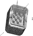
- FIG. 5 a perspective view illustrating the cap portion 25 in isolation is provided for clarity of description.
- the cap portion 25 may be generally cup-shaped and may define an interior cavity 30.
- a plurality of surface features 32 may extend from one or more interior surfaces of the cap portion 25 into the interior cavity 30.
- the surface features 32 are frustoconical protrusions with vertical ridges extending radially therefrom.
- the present disclosure is not limited in this regard, and various alternative embodiments of the cap portion 25 are contemplated in which the surface features 32 may additionally or alternatively include various ridges, protrusions, castellations, barriers, channels, contours, etc. of different shapes and sizes.
- the surface features 32 of the cap portion 25 may be disposed immediately adjacent the cover 19 and the underlying fusible element 14c, and the interior cavity 30 of the cap portion 25 may define an air pocket immediately adjacent the cover 19 and the underlying fusible element 14c.
- the air pocket defined by the cap portion 25 may provide an expansion space for containing the energy of the explosion.
- the surface features 32 may provide significant surface area between the fusible element 14c and the interior surfaces of the cap portion 25 to absorb the energy of the explosion.
- the risk of the fuse module 10 being ruptured is mitigated, which in-turn mitigates the risk of an arc in the melted fusible element 14c igniting volatile gases in the atmosphere surrounding the fuse module 10.
- the fuse module 10 may be assembled by arranging the mounting block 12, the fuse 14, the conductive ring 29, and the preformed (e.g., molded, 3D-printed, etc.) cap portion 25 together in the manner shown in FIG. 3 .
- the main body portion 23 of the housing 22 may then be overmolded onto and around the mounting block 12, the fuse 14, and the conductive ring 29, in abutment with the cap portion 25 of the housing 22.
- the molten material used to form the main body portion 23 of housing 22 during the overmolding process may melt, and may join with, the lip of the cap portion 25, resulting in a fluid-tight juncture between the cap portion 25 and the main body portion 23.
- the fuse module 10 is shown operatively installed in a protected circuit arrangement wherein the fuse module 10 is connected between a battery 40 and an insulated ring terminal 42 of a conductor 44.
- An electrically insulating screw 46 e.g., a metallic screw with an electrically insulating coating
- the conductive ring 29 extends through an aperture in an insulative coating 50 of the ring terminal 42 and engages a conductive (i.e., metal) portion 52 of the ring terminal 42.
- An electrically insulating ring 54 may be disposed between a metallic head 56 of the screw 46 and the conductive portion 52 of the ring terminal 42 for providing electrical insulating therebetween.
- the resilient, insulative coating 50 of the ring terminal 42 may engage, and form a seal with, the top surface of the main body portion 23.
- annular battery terminal 48 may extend through the aperture 26 in the bottom surface of the main body portion 23 and may engage the lower portion 14b of the fuse 14, and the annular lip 28 of the main body portion 23 may engage, and form a seal with, the top surface of the battery 40. An overcurrent-protected electrical connection is thereby provided between the battery 40 and the ring terminal 42.
- the fusible element 14c of the fuse module 10 is sealed within a resilient housing 22 having an energy-dissipating cap 25 so that any electrical arcing and resulting explosion that may occur in the fuse module 10 during an over-current condition are entirely contained to prevent ignition of volatile gases that may be present in the environment of the fuse module 10.
Landscapes
- Chemical & Material Sciences (AREA)
- Chemical Kinetics & Catalysis (AREA)
- Electrochemistry (AREA)
- General Chemical & Material Sciences (AREA)
- Fuses (AREA)
- Connection Of Batteries Or Terminals (AREA)
Applications Claiming Priority (2)
| Application Number | Priority Date | Filing Date | Title |
|---|---|---|---|
| US201862782973P | 2018-12-20 | 2018-12-20 | |
| US16/691,092 US11417490B2 (en) | 2018-12-20 | 2019-11-21 | Sealed battery fuse module with energy dissipating cap |
Publications (2)
| Publication Number | Publication Date |
|---|---|
| EP3671801A1 true EP3671801A1 (de) | 2020-06-24 |
| EP3671801B1 EP3671801B1 (de) | 2025-01-08 |
Family
ID=68732969
Family Applications (1)
| Application Number | Title | Priority Date | Filing Date |
|---|---|---|---|
| EP19212596.1A Active EP3671801B1 (de) | 2018-12-20 | 2019-11-29 | Abgedichtetes batteriesicherungsmodul mit energieableitkappe |
Country Status (4)
| Country | Link |
|---|---|
| US (1) | US11417490B2 (de) |
| EP (1) | EP3671801B1 (de) |
| KR (1) | KR102871007B1 (de) |
| CN (1) | CN111354611B (de) |
Cited By (1)
| Publication number | Priority date | Publication date | Assignee | Title |
|---|---|---|---|---|
| EP4174900A1 (de) * | 2021-10-22 | 2023-05-03 | Suzhou Littelfuse OVS Co., Ltd. | Abgedichtetes inline-sicherungsmodul |
Families Citing this family (1)
| Publication number | Priority date | Publication date | Assignee | Title |
|---|---|---|---|---|
| US11195683B1 (en) | 2021-02-11 | 2021-12-07 | Littelfuse, Inc. | Single bolt fuse assembly with an electrically isolated bolt |
Citations (3)
| Publication number | Priority date | Publication date | Assignee | Title |
|---|---|---|---|---|
| US7172462B1 (en) * | 2005-08-15 | 2007-02-06 | Yazaki North America, Inc. | Fuse |
| US20090066469A1 (en) * | 2007-09-10 | 2009-03-12 | Naeem Rahman | Battery fuse assembly |
| US20160372294A1 (en) * | 2015-02-14 | 2016-12-22 | Nanjing Sart Science & Technology Development Co., Ltd | Protective Element |
Family Cites Families (14)
| Publication number | Priority date | Publication date | Assignee | Title |
|---|---|---|---|---|
| US5645448A (en) * | 1995-10-16 | 1997-07-08 | Yazaki Corporation | Battery connecting module with fuse mounting |
| US6507265B1 (en) * | 1999-04-29 | 2003-01-14 | Cooper Technologies Company | Fuse with fuse link coating |
| US6902434B2 (en) * | 2002-07-23 | 2005-06-07 | Cooper Technologies Company | Battery fuse bus bar assembly |
| WO2007041529A2 (en) * | 2005-10-03 | 2007-04-12 | Littelfuse, Inc. | Fuse with cavity forming enclosure |
| US7192319B1 (en) * | 2005-11-28 | 2007-03-20 | Cooper Technologies Company | Insulated cable termination assembly and method of fabrication |
| JP2010092730A (ja) * | 2008-10-08 | 2010-04-22 | Yazaki Corp | バッテリヒューズユニット用保護カバー及びその着脱方法 |
| US8669840B2 (en) * | 2010-05-18 | 2014-03-11 | Littelfuse, Inc. | Fuse assembly |
| US8665056B2 (en) * | 2010-05-18 | 2014-03-04 | Littlefuse, Inc. | Fuse assembly |
| JP6437239B2 (ja) * | 2013-08-28 | 2018-12-12 | デクセリアルズ株式会社 | ヒューズエレメント、ヒューズ素子 |
| US9660249B2 (en) * | 2013-10-01 | 2017-05-23 | Samsung Sdi Co., Ltd. | Rechargeable battery having a fuse |
| US9472364B2 (en) * | 2014-05-02 | 2016-10-18 | Littelfuse, Inc. | Reflowable circuit protection device |
| US9824840B2 (en) * | 2014-09-05 | 2017-11-21 | Littelfuse, Inc. | Mechanical disconnect switch with integrated fuse protection |
| KR102086128B1 (ko) * | 2016-02-12 | 2020-03-06 | 주식회사 엘지화학 | 배터리 팩 및 이러한 배터리 팩을 포함하는 자동차 |
| JP6433469B2 (ja) * | 2016-10-04 | 2018-12-05 | 矢崎総業株式会社 | バッテリ用接続ユニット及びバッテリ用接続ユニットの取付構造 |
-
2019
- 2019-11-21 US US16/691,092 patent/US11417490B2/en active Active
- 2019-11-29 EP EP19212596.1A patent/EP3671801B1/de active Active
- 2019-12-17 KR KR1020190168820A patent/KR102871007B1/ko active Active
- 2019-12-18 CN CN201911313436.5A patent/CN111354611B/zh active Active
Patent Citations (3)
| Publication number | Priority date | Publication date | Assignee | Title |
|---|---|---|---|---|
| US7172462B1 (en) * | 2005-08-15 | 2007-02-06 | Yazaki North America, Inc. | Fuse |
| US20090066469A1 (en) * | 2007-09-10 | 2009-03-12 | Naeem Rahman | Battery fuse assembly |
| US20160372294A1 (en) * | 2015-02-14 | 2016-12-22 | Nanjing Sart Science & Technology Development Co., Ltd | Protective Element |
Cited By (2)
| Publication number | Priority date | Publication date | Assignee | Title |
|---|---|---|---|---|
| EP4174900A1 (de) * | 2021-10-22 | 2023-05-03 | Suzhou Littelfuse OVS Co., Ltd. | Abgedichtetes inline-sicherungsmodul |
| US12183531B2 (en) | 2021-10-22 | 2024-12-31 | Suzhou Littelfuse Ovs Co., Ltd. | Sealed inline fuse module |
Also Published As
| Publication number | Publication date |
|---|---|
| KR102871007B1 (ko) | 2025-10-16 |
| EP3671801B1 (de) | 2025-01-08 |
| US20200203110A1 (en) | 2020-06-25 |
| US11417490B2 (en) | 2022-08-16 |
| CN111354611A (zh) | 2020-06-30 |
| CN111354611B (zh) | 2025-01-28 |
| KR20200077435A (ko) | 2020-06-30 |
Similar Documents
| Publication | Publication Date | Title |
|---|---|---|
| US20190259556A1 (en) | Ventilated fuse housing | |
| CN106450063A (zh) | 二次电池 | |
| US10673056B2 (en) | Secondary battery | |
| US11417490B2 (en) | Sealed battery fuse module with energy dissipating cap | |
| US11017972B2 (en) | Solderless surface mount fuse | |
| EP3611751B1 (de) | Leitfähige verbindungsstruktur, multifunktioneller hochspannungsverbinder und batterieprodukt | |
| WO2018155161A1 (ja) | 温度ヒューズ及び電気接続箱 | |
| CN104115252B (zh) | 过电流保护装置 | |
| CN115188645B (zh) | 熔断器及电子设备 | |
| US11469069B1 (en) | Airtight surface mount fuse with insert cavity | |
| EP4174900B1 (de) | Abgedichtetes inline-sicherungsmodul | |
| JP2018181819A (ja) | サービスプラグ機能付き高電圧ヒューズ | |
| US11749483B1 (en) | Fuse with compartmentalized body and parallel fuse elements | |
| CN223471668U (zh) | 电芯组件、电池模组和电池包 | |
| KR20240072295A (ko) | 전기 퓨즈 | |
| CN111211023B (zh) | 保护元件 | |
| CN223898285U (zh) | 耐受大电流的电路保护元件 | |
| KR101222840B1 (ko) | 파워아울렛 | |
| CN212783363U (zh) | 高防护大功率保险盒 | |
| TWM669688U (zh) | 耐受大電流的電路保護元件 | |
| CN120126982A (zh) | 用于提高分断能力的具有铸造弧抑制材料的熔断器 | |
| KR200282809Y1 (ko) | 배선용 차단기 | |
| JPH0324029B2 (de) | ||
| JP2000173427A (ja) | 保護装置組立構体および保護装置 | |
| JPS61269826A (ja) | 車両用安全ヒユ−ズ |
Legal Events
| Date | Code | Title | Description |
|---|---|---|---|
| PUAI | Public reference made under article 153(3) epc to a published international application that has entered the european phase |
Free format text: ORIGINAL CODE: 0009012 |
|
| STAA | Information on the status of an ep patent application or granted ep patent |
Free format text: STATUS: THE APPLICATION HAS BEEN PUBLISHED |
|
| AK | Designated contracting states |
Kind code of ref document: A1 Designated state(s): AL AT BE BG CH CY CZ DE DK EE ES FI FR GB GR HR HU IE IS IT LI LT LU LV MC MK MT NL NO PL PT RO RS SE SI SK SM TR |
|
| AX | Request for extension of the european patent |
Extension state: BA ME |
|
| STAA | Information on the status of an ep patent application or granted ep patent |
Free format text: STATUS: REQUEST FOR EXAMINATION WAS MADE |
|
| 17P | Request for examination filed |
Effective date: 20201223 |
|
| RBV | Designated contracting states (corrected) |
Designated state(s): AL AT BE BG CH CY CZ DE DK EE ES FI FR GB GR HR HU IE IS IT LI LT LU LV MC MK MT NL NO PL PT RO RS SE SI SK SM TR |
|
| STAA | Information on the status of an ep patent application or granted ep patent |
Free format text: STATUS: EXAMINATION IS IN PROGRESS |
|
| 17Q | First examination report despatched |
Effective date: 20220831 |
|
| GRAP | Despatch of communication of intention to grant a patent |
Free format text: ORIGINAL CODE: EPIDOSNIGR1 |
|
| STAA | Information on the status of an ep patent application or granted ep patent |
Free format text: STATUS: GRANT OF PATENT IS INTENDED |
|
| INTG | Intention to grant announced |
Effective date: 20240805 |
|
| RIC1 | Information provided on ipc code assigned before grant |
Ipc: H01H 85/38 20060101ALN20240726BHEP Ipc: H01H 85/02 20060101ALN20240726BHEP Ipc: H01H 85/10 20060101ALN20240726BHEP Ipc: H01H 85/00 20060101ALI20240726BHEP Ipc: H01H 85/43 20060101ALI20240726BHEP Ipc: H01H 85/175 20060101AFI20240726BHEP |
|
| P01 | Opt-out of the competence of the unified patent court (upc) registered |
Free format text: CASE NUMBER: APP_48099/2024 Effective date: 20240821 |
|
| GRAS | Grant fee paid |
Free format text: ORIGINAL CODE: EPIDOSNIGR3 |
|
| GRAA | (expected) grant |
Free format text: ORIGINAL CODE: 0009210 |
|
| STAA | Information on the status of an ep patent application or granted ep patent |
Free format text: STATUS: THE PATENT HAS BEEN GRANTED |
|
| AK | Designated contracting states |
Kind code of ref document: B1 Designated state(s): AL AT BE BG CH CY CZ DE DK EE ES FI FR GB GR HR HU IE IS IT LI LT LU LV MC MK MT NL NO PL PT RO RS SE SI SK SM TR |
|
| REG | Reference to a national code |
Ref country code: GB Ref legal event code: FG4D |
|
| REG | Reference to a national code |
Ref country code: CH Ref legal event code: EP |
|
| REG | Reference to a national code |
Ref country code: DE Ref legal event code: R096 Ref document number: 602019064556 Country of ref document: DE |
|
| REG | Reference to a national code |
Ref country code: IE Ref legal event code: FG4D |
|
| REG | Reference to a national code |
Ref country code: LT Ref legal event code: MG9D |
|
| REG | Reference to a national code |
Ref country code: NL Ref legal event code: MP Effective date: 20250108 |
|
| REG | Reference to a national code |
Ref country code: AT Ref legal event code: MK05 Ref document number: 1758900 Country of ref document: AT Kind code of ref document: T Effective date: 20250108 |
|
| PG25 | Lapsed in a contracting state [announced via postgrant information from national office to epo] |
Ref country code: NL Free format text: LAPSE BECAUSE OF FAILURE TO SUBMIT A TRANSLATION OF THE DESCRIPTION OR TO PAY THE FEE WITHIN THE PRESCRIBED TIME-LIMIT Effective date: 20250108 |
|
| PG25 | Lapsed in a contracting state [announced via postgrant information from national office to epo] |
Ref country code: RS Free format text: LAPSE BECAUSE OF FAILURE TO SUBMIT A TRANSLATION OF THE DESCRIPTION OR TO PAY THE FEE WITHIN THE PRESCRIBED TIME-LIMIT Effective date: 20250408 |
|
| PG25 | Lapsed in a contracting state [announced via postgrant information from national office to epo] |
Ref country code: FI Free format text: LAPSE BECAUSE OF FAILURE TO SUBMIT A TRANSLATION OF THE DESCRIPTION OR TO PAY THE FEE WITHIN THE PRESCRIBED TIME-LIMIT Effective date: 20250108 |
|
| PG25 | Lapsed in a contracting state [announced via postgrant information from national office to epo] |
Ref country code: PL Free format text: LAPSE BECAUSE OF FAILURE TO SUBMIT A TRANSLATION OF THE DESCRIPTION OR TO PAY THE FEE WITHIN THE PRESCRIBED TIME-LIMIT Effective date: 20250108 |
|
| PG25 | Lapsed in a contracting state [announced via postgrant information from national office to epo] |
Ref country code: ES Free format text: LAPSE BECAUSE OF FAILURE TO SUBMIT A TRANSLATION OF THE DESCRIPTION OR TO PAY THE FEE WITHIN THE PRESCRIBED TIME-LIMIT Effective date: 20250108 |
|
| PG25 | Lapsed in a contracting state [announced via postgrant information from national office to epo] |
Ref country code: NO Free format text: LAPSE BECAUSE OF FAILURE TO SUBMIT A TRANSLATION OF THE DESCRIPTION OR TO PAY THE FEE WITHIN THE PRESCRIBED TIME-LIMIT Effective date: 20250408 Ref country code: IS Free format text: LAPSE BECAUSE OF FAILURE TO SUBMIT A TRANSLATION OF THE DESCRIPTION OR TO PAY THE FEE WITHIN THE PRESCRIBED TIME-LIMIT Effective date: 20250508 |
|
| PG25 | Lapsed in a contracting state [announced via postgrant information from national office to epo] |
Ref country code: HR Free format text: LAPSE BECAUSE OF FAILURE TO SUBMIT A TRANSLATION OF THE DESCRIPTION OR TO PAY THE FEE WITHIN THE PRESCRIBED TIME-LIMIT Effective date: 20250108 |
|
| PG25 | Lapsed in a contracting state [announced via postgrant information from national office to epo] |
Ref country code: LV Free format text: LAPSE BECAUSE OF FAILURE TO SUBMIT A TRANSLATION OF THE DESCRIPTION OR TO PAY THE FEE WITHIN THE PRESCRIBED TIME-LIMIT Effective date: 20250108 Ref country code: PT Free format text: LAPSE BECAUSE OF FAILURE TO SUBMIT A TRANSLATION OF THE DESCRIPTION OR TO PAY THE FEE WITHIN THE PRESCRIBED TIME-LIMIT Effective date: 20250508 |
|
| PG25 | Lapsed in a contracting state [announced via postgrant information from national office to epo] |
Ref country code: BG Free format text: LAPSE BECAUSE OF FAILURE TO SUBMIT A TRANSLATION OF THE DESCRIPTION OR TO PAY THE FEE WITHIN THE PRESCRIBED TIME-LIMIT Effective date: 20250108 Ref country code: GR Free format text: LAPSE BECAUSE OF FAILURE TO SUBMIT A TRANSLATION OF THE DESCRIPTION OR TO PAY THE FEE WITHIN THE PRESCRIBED TIME-LIMIT Effective date: 20250409 |
|
| PG25 | Lapsed in a contracting state [announced via postgrant information from national office to epo] |
Ref country code: AT Free format text: LAPSE BECAUSE OF FAILURE TO SUBMIT A TRANSLATION OF THE DESCRIPTION OR TO PAY THE FEE WITHIN THE PRESCRIBED TIME-LIMIT Effective date: 20250108 |
|
| PG25 | Lapsed in a contracting state [announced via postgrant information from national office to epo] |
Ref country code: SE Free format text: LAPSE BECAUSE OF FAILURE TO SUBMIT A TRANSLATION OF THE DESCRIPTION OR TO PAY THE FEE WITHIN THE PRESCRIBED TIME-LIMIT Effective date: 20250108 |
|
| PG25 | Lapsed in a contracting state [announced via postgrant information from national office to epo] |
Ref country code: SM Free format text: LAPSE BECAUSE OF FAILURE TO SUBMIT A TRANSLATION OF THE DESCRIPTION OR TO PAY THE FEE WITHIN THE PRESCRIBED TIME-LIMIT Effective date: 20250108 |
|
| REG | Reference to a national code |
Ref country code: DE Ref legal event code: R097 Ref document number: 602019064556 Country of ref document: DE |
|
| PG25 | Lapsed in a contracting state [announced via postgrant information from national office to epo] |
Ref country code: DK Free format text: LAPSE BECAUSE OF FAILURE TO SUBMIT A TRANSLATION OF THE DESCRIPTION OR TO PAY THE FEE WITHIN THE PRESCRIBED TIME-LIMIT Effective date: 20250108 |
|
| PG25 | Lapsed in a contracting state [announced via postgrant information from national office to epo] |
Ref country code: CZ Free format text: LAPSE BECAUSE OF FAILURE TO SUBMIT A TRANSLATION OF THE DESCRIPTION OR TO PAY THE FEE WITHIN THE PRESCRIBED TIME-LIMIT Effective date: 20250108 Ref country code: EE Free format text: LAPSE BECAUSE OF FAILURE TO SUBMIT A TRANSLATION OF THE DESCRIPTION OR TO PAY THE FEE WITHIN THE PRESCRIBED TIME-LIMIT Effective date: 20250108 |
|
| PG25 | Lapsed in a contracting state [announced via postgrant information from national office to epo] |
Ref country code: RO Free format text: LAPSE BECAUSE OF FAILURE TO SUBMIT A TRANSLATION OF THE DESCRIPTION OR TO PAY THE FEE WITHIN THE PRESCRIBED TIME-LIMIT Effective date: 20250108 |
|
| PG25 | Lapsed in a contracting state [announced via postgrant information from national office to epo] |
Ref country code: SK Free format text: LAPSE BECAUSE OF FAILURE TO SUBMIT A TRANSLATION OF THE DESCRIPTION OR TO PAY THE FEE WITHIN THE PRESCRIBED TIME-LIMIT Effective date: 20250108 |
|
| PLBE | No opposition filed within time limit |
Free format text: ORIGINAL CODE: 0009261 |
|
| STAA | Information on the status of an ep patent application or granted ep patent |
Free format text: STATUS: NO OPPOSITION FILED WITHIN TIME LIMIT |
|
| 26N | No opposition filed |
Effective date: 20251009 |
|
| PGFP | Annual fee paid to national office [announced via postgrant information from national office to epo] |
Ref country code: DE Payment date: 20250930 Year of fee payment: 7 |
|
| PGFP | Annual fee paid to national office [announced via postgrant information from national office to epo] |
Ref country code: GB Payment date: 20251001 Year of fee payment: 7 |
|
| PGFP | Annual fee paid to national office [announced via postgrant information from national office to epo] |
Ref country code: IT Payment date: 20251022 Year of fee payment: 7 |