EP3671273B1 - Système de localisation grossière de cibles coopératives mobiles pendant une mesure d'objet industriel basée sur un dispositif de suivi laser - Google Patents
Système de localisation grossière de cibles coopératives mobiles pendant une mesure d'objet industriel basée sur un dispositif de suivi laser Download PDFInfo
- Publication number
- EP3671273B1 EP3671273B1 EP18213695.2A EP18213695A EP3671273B1 EP 3671273 B1 EP3671273 B1 EP 3671273B1 EP 18213695 A EP18213695 A EP 18213695A EP 3671273 B1 EP3671273 B1 EP 3671273B1
- Authority
- EP
- European Patent Office
- Prior art keywords
- rftt
- cooperative target
- anchor
- modules
- rft
- Prior art date
- Legal status (The legal status is an assumption and is not a legal conclusion. Google has not performed a legal analysis and makes no representation as to the accuracy of the status listed.)
- Active
Links
- 238000005259 measurement Methods 0.000 title claims description 57
- 230000004807 localization Effects 0.000 title claims description 8
- 239000000523 sample Substances 0.000 claims description 31
- 238000001514 detection method Methods 0.000 claims description 27
- 238000011156 evaluation Methods 0.000 claims description 24
- 230000003287 optical effect Effects 0.000 claims description 20
- 230000005540 biological transmission Effects 0.000 claims description 8
- 230000003068 static effect Effects 0.000 claims description 6
- 238000004891 communication Methods 0.000 claims description 4
- 230000001133 acceleration Effects 0.000 claims description 3
- 230000005855 radiation Effects 0.000 description 20
- 238000005516 engineering process Methods 0.000 description 7
- 238000000034 method Methods 0.000 description 7
- 230000009471 action Effects 0.000 description 5
- 230000008685 targeting Effects 0.000 description 4
- 230000008569 process Effects 0.000 description 3
- 230000001960 triggered effect Effects 0.000 description 3
- 238000012986 modification Methods 0.000 description 2
- 230000004048 modification Effects 0.000 description 2
- 239000000919 ceramic Substances 0.000 description 1
- 230000008859 change Effects 0.000 description 1
- 238000013461 design Methods 0.000 description 1
- 230000006872 improvement Effects 0.000 description 1
- 238000007689 inspection Methods 0.000 description 1
- 238000012544 monitoring process Methods 0.000 description 1
- 230000000704 physical effect Effects 0.000 description 1
- 230000035484 reaction time Effects 0.000 description 1
- 230000003252 repetitive effect Effects 0.000 description 1
- 238000010845 search algorithm Methods 0.000 description 1
Images
Classifications
-
- G—PHYSICS
- G01—MEASURING; TESTING
- G01S—RADIO DIRECTION-FINDING; RADIO NAVIGATION; DETERMINING DISTANCE OR VELOCITY BY USE OF RADIO WAVES; LOCATING OR PRESENCE-DETECTING BY USE OF THE REFLECTION OR RERADIATION OF RADIO WAVES; ANALOGOUS ARRANGEMENTS USING OTHER WAVES
- G01S11/00—Systems for determining distance or velocity not using reflection or reradiation
- G01S11/02—Systems for determining distance or velocity not using reflection or reradiation using radio waves
- G01S11/026—Systems for determining distance or velocity not using reflection or reradiation using radio waves using moving transmitters
-
- G—PHYSICS
- G01—MEASURING; TESTING
- G01S—RADIO DIRECTION-FINDING; RADIO NAVIGATION; DETERMINING DISTANCE OR VELOCITY BY USE OF RADIO WAVES; LOCATING OR PRESENCE-DETECTING BY USE OF THE REFLECTION OR RERADIATION OF RADIO WAVES; ANALOGOUS ARRANGEMENTS USING OTHER WAVES
- G01S17/00—Systems using the reflection or reradiation of electromagnetic waves other than radio waves, e.g. lidar systems
- G01S17/86—Combinations of lidar systems with systems other than lidar, radar or sonar, e.g. with direction finders
-
- G—PHYSICS
- G01—MEASURING; TESTING
- G01B—MEASURING LENGTH, THICKNESS OR SIMILAR LINEAR DIMENSIONS; MEASURING ANGLES; MEASURING AREAS; MEASURING IRREGULARITIES OF SURFACES OR CONTOURS
- G01B11/00—Measuring arrangements characterised by the use of optical techniques
-
- G—PHYSICS
- G01—MEASURING; TESTING
- G01C—MEASURING DISTANCES, LEVELS OR BEARINGS; SURVEYING; NAVIGATION; GYROSCOPIC INSTRUMENTS; PHOTOGRAMMETRY OR VIDEOGRAMMETRY
- G01C15/00—Surveying instruments or accessories not provided for in groups G01C1/00 - G01C13/00
- G01C15/002—Active optical surveying means
-
- G—PHYSICS
- G01—MEASURING; TESTING
- G01S—RADIO DIRECTION-FINDING; RADIO NAVIGATION; DETERMINING DISTANCE OR VELOCITY BY USE OF RADIO WAVES; LOCATING OR PRESENCE-DETECTING BY USE OF THE REFLECTION OR RERADIATION OF RADIO WAVES; ANALOGOUS ARRANGEMENTS USING OTHER WAVES
- G01S11/00—Systems for determining distance or velocity not using reflection or reradiation
- G01S11/02—Systems for determining distance or velocity not using reflection or reradiation using radio waves
- G01S11/04—Systems for determining distance or velocity not using reflection or reradiation using radio waves using angle measurements
-
- G—PHYSICS
- G01—MEASURING; TESTING
- G01S—RADIO DIRECTION-FINDING; RADIO NAVIGATION; DETERMINING DISTANCE OR VELOCITY BY USE OF RADIO WAVES; LOCATING OR PRESENCE-DETECTING BY USE OF THE REFLECTION OR RERADIATION OF RADIO WAVES; ANALOGOUS ARRANGEMENTS USING OTHER WAVES
- G01S11/00—Systems for determining distance or velocity not using reflection or reradiation
- G01S11/02—Systems for determining distance or velocity not using reflection or reradiation using radio waves
- G01S11/06—Systems for determining distance or velocity not using reflection or reradiation using radio waves using intensity measurements
-
- G—PHYSICS
- G01—MEASURING; TESTING
- G01S—RADIO DIRECTION-FINDING; RADIO NAVIGATION; DETERMINING DISTANCE OR VELOCITY BY USE OF RADIO WAVES; LOCATING OR PRESENCE-DETECTING BY USE OF THE REFLECTION OR RERADIATION OF RADIO WAVES; ANALOGOUS ARRANGEMENTS USING OTHER WAVES
- G01S17/00—Systems using the reflection or reradiation of electromagnetic waves other than radio waves, e.g. lidar systems
- G01S17/88—Lidar systems specially adapted for specific applications
- G01S17/89—Lidar systems specially adapted for specific applications for mapping or imaging
-
- G—PHYSICS
- G01—MEASURING; TESTING
- G01S—RADIO DIRECTION-FINDING; RADIO NAVIGATION; DETERMINING DISTANCE OR VELOCITY BY USE OF RADIO WAVES; LOCATING OR PRESENCE-DETECTING BY USE OF THE REFLECTION OR RERADIATION OF RADIO WAVES; ANALOGOUS ARRANGEMENTS USING OTHER WAVES
- G01S5/00—Position-fixing by co-ordinating two or more direction or position line determinations; Position-fixing by co-ordinating two or more distance determinations
- G01S5/02—Position-fixing by co-ordinating two or more direction or position line determinations; Position-fixing by co-ordinating two or more distance determinations using radio waves
- G01S5/0257—Hybrid positioning
- G01S5/0263—Hybrid positioning by combining or switching between positions derived from two or more separate positioning systems
- G01S5/0264—Hybrid positioning by combining or switching between positions derived from two or more separate positioning systems at least one of the systems being a non-radio wave positioning system
-
- G—PHYSICS
- G01—MEASURING; TESTING
- G01S—RADIO DIRECTION-FINDING; RADIO NAVIGATION; DETERMINING DISTANCE OR VELOCITY BY USE OF RADIO WAVES; LOCATING OR PRESENCE-DETECTING BY USE OF THE REFLECTION OR RERADIATION OF RADIO WAVES; ANALOGOUS ARRANGEMENTS USING OTHER WAVES
- G01S3/00—Direction-finders for determining the direction from which infrasonic, sonic, ultrasonic, or electromagnetic waves, or particle emission, not having a directional significance, are being received
- G01S3/02—Direction-finders for determining the direction from which infrasonic, sonic, ultrasonic, or electromagnetic waves, or particle emission, not having a directional significance, are being received using radio waves
- G01S3/14—Systems for determining direction or deviation from predetermined direction
- G01S3/46—Systems for determining direction or deviation from predetermined direction using antennas spaced apart and measuring phase or time difference between signals therefrom, i.e. path-difference systems
Definitions
- This invention relates to a system which is configured for roughly localising moveable cooperative targets during laser tracker based industrial object measurement aiding radio frequency (RF) based technology, in order to support the optical detector based rough localisation functionality of a laser tracker.
- RF radio frequency
- Industrial object measurement using a laser tracker is based on localising and tracking a cooperative target which is placed on a surface of an object to be measured or on localising and tracking a cooperative target which is comprised by a measurement probe.
- the measurement probe also referred to as target probe can be a touch probe which is brought into contact with a surface of an object to be measured wherein after establishing contact with the surface the determination of coordinate information of the point where the touch probe touches the surface is triggered.
- the target probe can also be a non-contact probe.
- the non-contact probe sends optical distance measurement radiation to a corresponding point on the surface of an object to be measured, wherein coordinate information of the point being illuminated by the optical distance measurement radiation is determined based on a part of the measurement radiation being back reflected to the probe and based on knowing under which angle the point on the surface is illuminated.
- laser trackers are used for industrial measurement, e.g. for coordinative position determination of points of a component such as a vehicle body for example in the context of an inspection or for continuous position monitoring of a moving machine part.
- Such laser trackers are designed for coordinative position determination of said points of a component and usually for continuous tracking of a cooperative target point, as for example disclosed in US2013229512 A1 .
- a cooperative target point can be represented by a retroreflective unit (e.g. cube prism) which is targeted by an optical measurement beam generated by a beam source of the measuring device or of the measuring apparatus, in particular a laser beam.
- the laser beam is reflected back to the measuring apparatus in a parallel fashion, the reflected beam being detected by detection means of the apparatus.
- an emission direction and respectively a reception direction of the beam are ascertained, for example by means of sensors for angle measurement which are assigned to a deflection mirror or a targeting unit of the system.
- a distance from the measuring apparatus to the cooperative target is ascertained, e.g. by means of time-of-flight or phase difference measurement or by means of the Fizeau principle.
- the position coordinates of the points of a component are determined on the basis of the emission direction and respectively the reception direction and the distance.
- laser trackers in the prior art comprise at least one distance measuring device, wherein the latter can be designed e.g. as an interferometer (IFM). Since such distance measuring devices can measure only relative changes in distance, in order to determine an absolute distance value so-called absolute distance measuring devices (ADM) are installed in present-day laser trackers.
- a combination of an absolute distance measuring device and an interferometer for determining distance is for example known from WO 2007/079600 A1 .
- an offset of the received measurement beam from a zero position is ascertained on a fine targeting sensor.
- a fine targeting sensor By means of this measurable offset, it is possible to determine a difference in position between the center of a retroreflector and the impingement point of the laser beam on the reflector and it is possible to correct or readjust the alignment of the laser beam depending on this deviation in such a way that the offset on the fine targeting sensor is reduced, in particular is "zero", and the beam is thus aligned in the direction of the reflector center.
- the readjustment of the laser beam alignment continuous target tracking of the target point can be carried out and the distance and position of the target point can be determined continuously relative to the measuring device.
- the readjustment can be realized in this case by means of a change in alignment of the deflection mirror provided for deflecting the laser beam, said deflection mirror being movable in a motorized manner, and/or by pivoting of the targeting unit comprising the beam-guiding laser optical unit.
- the determination of coordinate information of a point on the surface of an object to be measured is based on the precise coordinate information of the cooperative target.
- the precise coordinate information of the cooperative target is referred to in the following as the fine position of the cooperative target.
- Said fine position of a cooperative target is determined based on sending distance measurement radiation emitted by a distance measurement radiation source from the laser tracker to the cooperative target where parts of the distance measurement radiation are back reflected to the laser tracker and based on determining the angles under which the distance measurement radiation is being sent towards the cooperative target. Therefore, the determination of the fine position of the cooperative target necessitates a continuous line of sight contact between the laser tracker and the cooperative target such that the cooperative target can be targeted with the corresponding radiation.
- the laser tracker is configured for automatically detecting the rough location of the cooperative target and based thereon for detecting the fine position of the cooperative target and for tracking the cooperative target e.g. while the target is moving.
- the efficiency is directly coupled to the amount of user-input actions needed in order to initiate the measuring job and to keep the measuring job running and to the time effort associated with each user-input action.
- the invention relates to a system configured for rough localization of moveable cooperative targets during laser tracker based industrial object measurement, comprising at least one laser tracker, having a moveable upper part being moveably connected to a base part, an optical target rough location detector configured for automatically detecting a rough location of a cooperative target within a rough location field of view, a target fine position detector configured for automatically detecting a fine position of a cooperative target and tracking a cooperative target within a fine position field of view, motors for changing an orientation of the moveable upper part, a motor controller, and a computer, a first and a second radio frequency telegram (RFT) transceiver (RFTT) anchor-module, wherein each RFTT anchor-module's position is referenced to the laser tracker, a cooperative target associated with a RFTT tag-module, and associated with each of the RFTT tag- and anchor-modules an evaluation unit configured for determining a RFT-transmission specific parameter based on the transmission of RFTs between the RF
- a cooperative target is a target which cooperates with the optical target rough location detector and the target fine position detector such that rough location detection radiation which is emitted from a rough location detection radiation source and being reflected by the cooperative target can be detected by the optical target rough location detector and such that fine position detection radiation which is emitted from a fine position detection radiation source and being reflected by the cooperative target can be detected and tracked by the target fine position detector.
- a cooperative target can be a retro-reflecting target or another type of cooperative target such as a sphere in particular a metallic or ceramic sphere or a similar target which cooperates with the optical target rough location detector and target fine position detector such that a rough location of the cooperative target can be determined and such that the cooperative target can be detected and tracked accordingly.
- the optical target rough location detector of the laser tracker may be based on a light-sensitive CMOS/CCD/CID pixel-sensor.
- the sensor may comprise an array of pixels arranged on a sensor area.
- the target fine position detector can be based on a light-sensitive CMOS/CCD/CID pixel-sensor as well or on a position sensitive detector (PSD) being configured for determining a deviation of a position where fine position detection radiation is detected from a detector zero position. If both the optical target rough location detector and the target fine position detector are based on a pixel-sensor they can be combined in one shared pixel-array.
- the laser tracker's computer may comprise a wireless data transceiver module which is configured for transmitting RFT-transmission specific data e.g. the RFT-transmission specific parameters between the computer and the evaluation units of the RFTT anchor- and tag-modules.
- a RFT can be any kind of electromagnetic radio frequency signal which serves the purpose of information and/or data transmission between transceivers or from a sending transceiver to a receiving transceiver. Thereby the RFT or signal can either have a package-like character or be a continuously transmitted RFT or electromagnetic radio frequency signal.
- the base part of the laser tracker comprises at least one of the RFTT anchor-modules.
- the laser tracker comprises at least two of the RFTT anchor-modules.
- At least one of the RFTT anchor-modules has a wired connection to the laser tracker's computer, wherein the associated evaluation unit provides the RFT-transmission specific parameters to the computer via the wired connection.
- the determined RFT-transmission specific parameter refers to one of the phase of the RFT, the time of flight of the RFT and the intensity of the RFT and the computer is configured for determining an angle of arrival of the RFTs based on one of the phases of the RFTs, the times of flight of the RFTs and the intensities of the RFTs, in particular based on one of a differential evaluation of the phases of the RFTs, a differential evaluation of the times of flight of the RFTs and a differential evaluation of the intensities of the RFTs.
- the principle of measuring the angle of arrival might be well suited for being applied e.g. if two RFTT anchor-modules are comprised by the laser tracker.
- the RFT-transmission specific parameter refers to the time of flight of the RFT and the evaluation units are configured for determining distances between the RFTT anchor- and tag-modules based on the times of flight of the RFTs.
- the rough location is determined based on the distances between the RFTT anchor- and tag-modules and/or based on the angles of arrival of the RFT.
- the rough location may be a rough direction only.
- the principle of angle of arrival measurement may be based on determining differences between correspondingly determined RFT-transmission specific parameters (e.g. differences in time of flight between the received RFTs, differences in phases between the received RFTs, differences in RFT intensities between the received RFTs). Thereby no absolute distances between anchors and the tag have to be determined.
- the RFTT tag-module associated with the cooperative target is comprised by one of the cooperative target, a cooperative target holder, and a measurement probe comprising the cooperative target.
- a measurement probe may be e.g. a touch probe, a non-contact probe or a cooperative target as such which e.g. is permanently installed on an object to be measured. Furthermore, the measurement probe can be manually guided by an operator or automatically e.g. by a robot. In case of a touch probe the probe is brought into contact with a surface of an object to be measured, whereafter the determination of coordinate information of the point where the probe touches the surface is triggered.
- optical distance measurement radiation is sent from the probe to a corresponding point on the surface of an object to be measured, whereby coordinate information of the point being illuminated by the optical distance measurement radiation is determined based on a part of the distance measurement radiation back reflected to the probe head and based on knowing under which angle the point on the surface is illuminated.
- each of the RFTT tag- and anchor-modules comprises the associated evaluation unit.
- the system comprises further RFT tag-modules each being associated with one of an automated guided vehicle (AGV), a robot, an unmanned aerial vehicle (UAV), and an operator
- the computer is further configured for determining a rough location of the AGV, robot, UAV and the operator based on the RFT-transmission specific parameters determined by the evaluation units, and identifying based on the rough location of the AGV, robot, UAV and operator a mutual approximation below a minimum distance between at least two of a laser tracker, an AGV, a robot, an UAV, and an operator.
- the system comprises at least two laser trackers, wherein the RFTT anchor-modules comprise each a near field communication (NFC) module in particular a passively powered radio frequency identification (RFID) module, and the cooperative target is associated with a further NFC-module, wherein the NFC-modules of the RFTT anchor-modules are configured for automatically detecting a nearby NFC-module being associated with the cooperative target, and providing detection information related to the detection event to the computers, wherein the computers are further configured for determining based on said detection information one of the laser trackers, which then determines the rough location of the cooperative target in order to bring the cooperative target within the rough location field of view.
- NFC near field communication
- RFID radio frequency identification
- the NFC-module being associated with the cooperative target is comprised by one of the cooperative target, a cooperative target holder, a measurement probe comprising the cooperative target, an operator, in particular a hand-held mobile device being carried by the operator, and the RFTT tag-module being associated with the cooperative target.
- the system further comprises static objects being referenced to the laser tracker and a display device
- the computer is further configured for providing rough location information related to determined rough locations to the display device for displaying the rough locations within a virtual map comprising referenced positions of laser trackers, the RFTT anchor-modules, and the static objects being referenced to the laser trackers.
- the RFTT anchor- and tag-modules comprise an inertial measurement unit (IMU), wherein the IMU is configured to provide IMU-data based on measured accelerations to the computer and wherein the computer is configured to determine the rough location of the cooperative target further based on the IMU-data.
- IMU inertial measurement unit
- the RFT is an ultra-wide band telegram (UWBT)
- the RFTT anchor- and tag-modules are ultra-wide band (UWB) telegram transceiver (UWBTT) anchor- and tag-modules
- the evaluation units are configured for determining a UWBT-transmission specific parameter based on the transmission of UWBTs between the UWBTT anchor- and tag-modules and providing said UWBT-transmission specific parameter to the computer
- the computer is configured for determining a rough location of the cooperative target based on the UWBT-transmission specific parameters determined by the evaluation units and providing based on the determined rough location control information to the motor controller for facing the upper part of the laser tracker to the cooperative target in order to bring the cooperative target within the rough location field of view.
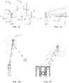
- Figure 1a shows a system according to the invention to be used for industrial laser tracker based object measurement.
- the state of the art automatic target finding functionality of generic laser trackers (not shown) is a reliable feature providing a quick and convenient way to lock the fine position detection radiation, onto a cooperative target, e.g. a prism, a sphere or a similar target which reflects at least parts of the fine position detection radiation sent from the laser tracker back to the laser tracker.
- the cooperative target can be comprised e.g. by a cooperative target holder, a measurement probe or be fixed to the object to be measured.
- the functionality is based on using an optical target rough location detector and a target fine position detector each being associated with its specific field of view (FoV).
- the FoV of the optical target rough location detector is larger than the FoV of the target fine position detector.
- the detection and tracking of a cooperative target is usually a two-step process wherein in a first step the optical target rough location detector is trying to detect the target within its larger FoV.
- the upper part of the laser tracker is faced to the detected rough location of the cooperative target and the target fine position detector is then capable of detecting the cooperative target within its smaller FoV and to precisely track the cooperative target.
- This procedure has its limits.
- the cooperative target must be illuminated with sufficient energy density to allow its reliable detection.
- FIG. 1a and 1b illustrate only schematically how the automatic target finding functionality of generic laser trackers is improved according to the inventive system (1).
- the system comprises a laser tracker (2) with a moveable upper part (3), a base part (4), an optical target rough location detector having a rough location field of view (5), a target fine position detector having a fine position field of view (6), two RFTT anchor-modules (7, 7') and a cooperative target (8) being associated with a RFTT tag-module (9).
- Associated can mean e.g. attached to the cooperative target, comprised by a cooperative target holder, comprised by a measurement probe comprising the cooperative target or being carried by an operator carrying the cooperative target, without being limited to the mentioned enumeration.
- the laser tracker is not facing to the cooperative target, meaning that the cooperative target is neither within the rough location field of view nor within the fine position field of view. Without the inventive system, in such a situation, an operator would have to align the upper part of the laser tracker in order to bring the cooperative target within the rough location field of view or even within the fine position field of view.
- the system (1) allows in a situation as illustrated in figure 1a to automatically determine a rough location of the cooperative target, based on the RFT transmission (10, 10') between the RFTT anchor- and tag-modules, and automatically instruct the laser tracker based on the determined rough location of the cooperative target to face the upper part to the cooperative target in order to bring the cooperative target within at least the rough location field of view.
- the operator does not need to take any action.
- the automatic target finding functionality will take over the further detection and tracking of the cooperative target whereby the fine position detection radiation (11) is locked onto the cooperative target.
- this process can be triggered automatically or "on-demand" by a user input action (e.g.
- Referenced positions of the RFTT anchor-modules can e.g. be determined in the set-up phase using the laser tracker of the system, which is being extended by the RF-technology based localisation system.
- the rough location of the cooperative target may be determined based on the RFT-transmission specific parameters determined by the evaluation units and the target fine position detector may automatically detect and track the cooperative target based on the asdetermined rough location of the cooperative target.
- the determination of the rough location of the cooperative target based on the RFT-transmission specific parameters may be accurate enough to initiate automatic detection and tracking by the target fine position detector. Then, the determination of the cooperative target's rough location by the target rough location detector could become at least partially obsolete.
- the upper part of the laser tracker could in a first step be faced towards the rough location of the cooperative target, determined based on the RFT-transmission specific parameters, and if the cooperative target would not be detected by the target fine position detector the upper part of the laser tracker could perform a spiral movement starting at the rough location of the cooperative target and around said rough location in an outward direction until the cooperative target can be detected and tracked by the target fine position detector. Instead of a spiral movement it could be sufficient to perform a one dimensional movement, e.g. in the case where only one parameter (e.g. the azimuth angle or the angle of elevation) could not be determined accurately enough, until the cooperative target can be detected and tracked by the target fine position detector.
- only one parameter e.g. the azimuth angle or the angle of elevation
- the determination of the rough location (can also be a rough direction only) of the cooperative target is based on the transmission of RFTs between the RFTT anchor- and tag-modules, wherein the transmission specific parameter can e.g. refer to the time of flight of the RFT or to a physical property of the RFT itself (e.g. intensity, phase) which is characteristic for a positional relationship between RFTT anchor- and tag-modules.
- the transmission specific parameter can e.g. refer to the time of flight of the RFT or to a physical property of the RFT itself (e.g. intensity, phase) which is characteristic for a positional relationship between RFTT anchor- and tag-modules.
- Based thereon e.g. distances or angles between RFTT anchor- and tag-modules can be determined by techniques related to the ones known as e.g. angle of arrival measurement, multi-lateration, tri-angulation.
- various algorithms such as Kalman filters can be used, which allow further improvement of system performance (in terms of accuracy
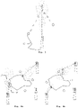
- FIG. 2a and 2b Advantageous embodiments of the invention are illustrated in figure 2a and 2b .
- one of the RFTT anchor-modules is integrated into the base part of the laser tracker and thereby has a position referenced to the laser tracker. Having one RFTT anchor-module integrated in the base part only at least one further RFTT anchor-module with a referenced position is sufficient to determine a rough location of the cooperative target according to the invention. If a RFTT anchor-module is integrated in the laser tracker, a RFT could further be used e.g. for time synchronization or propagation of various events such as measurement triggers.
- two RFTT anchor-modules are integrated in the laser tracker, e.g.
- the integrated RFTT anchor-modules require a spacing between them. If two RFTT anchor-modules are integrated e.g. in the upper (rotating) part of the laser tracker (see figure 2b ) a radial direction to the RFTT tag-module and therefore to the associated cooperative target can be estimated. The estimation is ambiguous since it cannot be distinguished between front and rear of the laser tracker.
- This ambiguity can be removed by implementing repeated measurements with different angles of rotation (usually this is an iterative/repetitive process as seen during target tracking) to recover the depth information, thus allowing determination of the radial direction.
- a vertical search algorithm making use of the target rough location detector and its field of view could be used.
- At least one of the RFTT anchor-modules can have a wired connection (12) to the laser tracker's computer.
- the RFT-transmission specific parameters are then provided to the laser tracker's computer via the wired connection.
- all the RFTT anchor-modules have a wired connection to the laser tracker's computer.
- the rough location of the cooperative target is determined based on a RFT-transmission specific parameter.
- a RFT is transmitted between the RFTT anchor- and tag-modules. E.g. by sending a RFT from a first RFTT anchor-module to the tag-module the time of flight of the RFT can be measured. Based on the measured time of flight a rough distance from the RFTT anchor- to the RFTT tag-module and thereby to the associated cooperative target can be determined.
- Determining a second rough distance from the second RFTT anchor-module to the RFTT tag-module and thereby to the associated cooperative target allows to determine at least a possible rough direction or a rough location of the RFTT tag-module and the associated cooperative target, wherein said rough location or direction is used to face the upper part of the laser tracker to the cooperative target in order to bring the cooperative target within the rough location field of view.
- the method allows distance measurements between a RFTT tag-module and a RFTT anchor-module with a precision down to a couple of centimetres.
- Another possibility would be to send a RFT from each of the RFTT anchor-modules to the RFTT tag-module and use the difference between the time of flight of the RFTs according to the principle of the measurement of the angle of arrival for determining at least a rough direction or rough location of the RFTT tag-module and thereby the associated cooperative target.
- the RFTT tag-module can be comprised by the cooperative target itself, e.g. attached to it, by a cooperative target holder, e.g. a stick, or by a measurement probe comprising the cooperative target. This as well provides the necessary spatial proximity of the RFTT tag-module to the cooperative target.
- Such objects can e.g. be automated guided vehicles (AGVs), robots or unmanned aerial vehicles (UAVs). Not only other objects but also operators in general can be associated or have further RFTT tag-modules.
- AGVs automated guided vehicles
- UAVs unmanned aerial vehicles
- Not only other objects but also operators in general can be associated or have further RFTT tag-modules.
- This information can then be processed by the laser trackers computer in order to determine distances between the objects and operators present on the measurement scene. Said distance information can then be monitored in order to avoid mutual approximations below a minimum distance between the laser tracker, AGVs, robots, UAVs and operators. Thereby collisions can be avoided.
- the RFTT anchor-modules can be integrated in AGVs, robots or UAVs as well. Referencing can also be achieved by e.g. steering an AGV from an initial referenced position to the desired destination.
- any other device available having a RFTT anchor-module can be used for referencing e.g. such as coordinate-measuring machines, measurement arms, handheld-devices, controllers, any other battery operated or stationary third-party systems.
- the laser tracker system can be used in the set-up phase to determine the referenced position of each of the RFTT anchor-modules.
- the system can comprise two laser trackers or more and each of the RFTT anchor-modules further comprises a near field communication (NFC) module (13).
- NFC near field communication
- the cooperative target is associated with a NFC-module as well (13').
- NFC modules are typically uniquely identifiable.
- the computers can decide based on the detection information, e.g.
- the NFC-module which is associated with the cooperative target can be comprised either by the cooperative target itself, by a cooperative target holder, e.g. a stick, by a measurement probe comprising the cooperative target, by an operator who is measuring the object, e.g. the operator carries a mobile device having the NFC-module, or by the RFTT tag-module which is associated with the cooperative target.
- static objects of the measurement scene and a display device can be comprised by the system.
- the computer of the laser tracker is further configured for providing rough location information related to the determined rough locations of e.g. the cooperative targets, the AGVs, the UAVs and the operators to the display device for displaying said rough locations within a virtual map which comprises the referenced positions of the laser trackers, RFTT anchor-modules and the static objects.
- a supervisor can monitor the whole measurement scene and measurement job based on referenced position data and determined rough locations aiding RF based technology.
- the RFTT anchor- and tag-modules can each comprise an inertial measurement unit (IMU).
- IMU inertial measurement unit
- Each inertial measurement unit is configured for providing IMU-data related to measured accelerations in 3 directions being mainly perpendicular to each other to the computer of the laser tracker.
- the computer is further configured for determining rough locations of RFTT tag-modules and thereby of associated cooperative targets, UAVS, AGVs, operators based on related IMU-data.
- the IMU-data based determination of rough locations can e.g. serve as backup solution in case the RF based technology is not operable.
- the used RF technology refers to the ultra-wide band (UWB) technology.
- UWB ultra-wide band
- UWB telegrams (UWBT), UWB telegram transceiver (UWBTT) anchor- and tag-modules and UWBT-transmission specific parameters are involved in the determination of rough locations of UWBTT tag-modules and associated cooperative targets, UAVs, AGVs and operators.
- RFTT anchor- and tag-modules have the same functionality they can be used vice-versa depending on the use-case.
- a RFTT anchor-module which was used during a first measurement job as RFTT anchor-module could become a RFTT tag-module during the next measurement job and vice-versa.
- the RFT can comprise further information e.g. related to the identification of the RFTT anchor- and tag-modules and associated cooperative targets, UAVs, AGVs, operators and objects. Based thereon an asset management system could be implemented as well.
Claims (15)
- Système (1) configuré pour la localisation grossière, pendant la mesure d'un objet industriel au moyen d'un laser de poursuite, de cibles coopératives mobiles, comprenant :• au moins un laser de poursuite (2), comportant :o une partie supérieure (3) mobile raccordée de manière mobile à une pièce de base (4),o un capteur optique de localisation grossière de cible configuré pour détecter automatiquement une localisation grossière d'une cible coopérative (8) dans un champ de vision de localisation grossière (5),o un capteur de position fine de cible configuré pour détecter automatiquement une position fine d'une cible coopérative et pour poursuivre une cible coopérative dans un champ de vision de position fine (6),o des moteurs pour modifier l'orientation de la partie supérieure mobile,o un contrôleur de moteur, eto un ordinateur,• un premier et un deuxième module d'ancrage (7, 7') d'émetteur-récepteur de télégramme radiofréquence (TRF) (module d'ancrage ERTRF), la position de chaque module d'ancrage ERTRF étant référencée vis-à-vis du laser de poursuite,• une cible coopérative (8) associée à un module de balise ERTRF (9), et• une unité d'évaluation associée à chacun des modules de balise et d'ancrage ERTRF, configurée pour déterminer un paramètre spécifique à la transmission TRF en se fondant sur la transmission de TRF (10, 10') entre les modules d'ancrage et de balise ERTRF et pour fournir à l'ordinateur ledit paramètre spécifique à la transmission TRF,dans lequel l'ordinateur est configuré pour :o déterminer une localisation grossière de la cible coopérative en se fondant sur les paramètres spécifiques à la transmission TRF déterminés par les unités d'évaluation, eto fournir au contrôleur de moteur des informations de commande fondées sur ladite localisation grossière déterminée, pour que la partie supérieure du laser de poursuite soit tournée vers la cible coopérative afin d'amener la cible coopérative dans le champ de vision de localisation grossière.
- Système selon la revendication 1, dans lequel la pièce de base du laser de poursuite comprend au moins un des modules d'ancrage ERTRF.
- Système selon la revendication 1, dans lequel le laser de poursuite comprend au moins deux des modules d'ancrage ERTRF.
- Système selon la revendication 1, dans lequel au moins un des modules d'ancrage ERTRF dispose d'une connexion filaire (12) à l'ordinateur du laser de poursuite, l'unité d'évaluation associée fournissant les paramètres spécifiques à la transmission TRF à l'ordinateur via la connexion filaire.
- Système selon l'une quelconque des revendications précédentes, dans lequel le paramètre spécifique à la transmission TRF déterminé se réfère à la phase du TRF, au temps de parcours du TRF ou à l'intensité du TRF, l'ordinateur étant configuré pour déterminer un angle d'incidence des TRF en se fondant sur la phase des TRF, le temps de parcours des TRF ou l'intensité des TRF, notamment sur une évaluation différentielle des phases de TRF, une évaluation différentielle des temps de parcours de TRF ou une évaluation différentielle des intensités de TRF.
- Système selon l'une quelconque des revendications précédentes, dans lequel le paramètre spécifique à la transmission TRF se réfère au temps de parcours du TRF et dans lequel les unités d'évaluation sont configurées pour déterminer des distances entre les modules d'ancrage et de balise ERTRF en se fondant sur le temps de parcours des TRF.
- Système selon la revendication 5 ou 6, dans lequel la détermination de la localisation grossière est fondée sur les distances entre les modules d'ancrage et de balise ERTRF et/ou sur les angles d'incidence du TRF.
- Système selon l'une quelconque des revendications précédentes, dans lequel le module de balise ERTRF associé à la cible coopérative est compris dans :o la cible coopérative,o un support de cible coopérative, ouo une sonde de mesure comprenant la cible coopérative.
- Système selon l'une quelconque des revendications précédentes, dans lequel chacun des modules d'ancrage et de balise ERTRF comprend l'unité d'évaluation associée.
- Système selon la revendication 1 comprenant d'autres modules de balise ERTRF, chacun étant associé à :o un véhicule à guidage automatique (VGA),o un robot,o un aéronef téléguidé, ouo un opérateur,dans lequel l'ordinateur est en outre configuré pour :o déterminer une localisation grossière du VGA, du robot, de l'aéronef téléguidé ou de l'opérateur en se fondant sur les paramètres spécifiques à la transmission TRF déterminés par les unités d'évaluation, eto identifier, en se fondant sur la localisation grossière du VGA, du robot, de l'aéronef téléguidé ou de l'opérateur, un rapprochement mutuel en deçà d'une distance minimale entre au moins deux des éléments suivants :i. un laser de poursuite,ii. un VGA,iii. un robot,iv. un aéronef téléguidé, etv. un opérateur.
- Système selon l'une quelconque des revendications précédentes, comprenant un autre laser de poursuite, dans lequelo les modules d'ancrage ERTRF comprennent chacun un module de communication en champ proche (CCP) (13), eto la cible coopérative est associée à un autre module CCP (13'),les modules CCP des modules d'ancrage ERTRF étant configurés pour :o détecter automatiquement un module CCP proche associé à la cible coopérative, eto fournir aux ordinateurs des informations de détection relatives à l'événement de détection,les ordinateurs étant en outre configurés pour déterminer, en se fondant sur lesdites informations de détection, l'un des lasers de poursuite, lequel détermine ensuite la localisation grossière de la cible coopérative afin d'amener la cible coopérative dans son champ de vision de localisation grossière.
- Système selon la revendication 11, dans lequel le module CCP associé à la cible coopérative est compris dans :o la cible coopérative,o un support de cible coopérative,o une sonde de mesure comprenant la cible coopérative,o un opérateur, notamment un appareil mobile tenu à la main par l'opérateur, ouo le module de balise ERTRF associé à la cible coopérative.
- Système selon l'une quelconque des revendications précédentes, comprenant en outre des objets statiques référencés vis-à-vis du laser de poursuite et un dispositif d'affichage, et dans lequel l'ordinateur est en outre configuré pour fournir au dispositif d'affichage des informations de localisation grossière relatives aux localisations grossières déterminées, afin que lesdites localisations grossières soient affichées sur une carte virtuelle comprenant les positions référencées :o des lasers de poursuite,o des modules d'ancrage ERTRF, eto des objets statiques référencés vis-à-vis des lasers de poursuite.
- Système selon l'une quelconque des revendications précédentes, les modules d'ancrage et de balise ERTRF comprenant une centrale inertielle (IMU), ladite IMU étant configurée pour fournir à l'ordinateur des données IMU fondées sur des accélérations mesurées, et l'ordinateur étant configuré pour déterminer la localisation grossière de la cible coopérative en se fondant en outre sur les données IMU.
- Système selon l'une quelconque des revendications précédentes, dans lequel :o le TRF est un télégramme à ultra large bande (UWBT),o les modules d'ancrage et de balise ERTRF sont des modules d'ancrage et de balise d'émetteur-récepteur (ERTUWB) de télégramme à ultra large bande (UWB),o les unités d'évaluation sont configurées pour déterminer un paramètre spécifique à la transmission UWBT en se fondant sur la transmission des UWBT entre les modules d'ancrage et de balise ERTUWB et pour fournir à l'ordinateur ledit paramètre spécifique à la transmission UWBT, etl'ordinateur est configuré pour déterminer une localisation grossière de la cible coopérative en se fondant sur les paramètres spécifiques à la transmission UWBT déterminés par les unités d'évaluation et pour fournir au contrôleur de moteur des informations de commande fondées sur ladite localisation grossière déterminée, pour que la partie supérieure du laser de poursuite soit tournée vers la cible coopérative afin d'amener la cible coopérative dans le champ de vision de localisation grossière.
Priority Applications (3)
| Application Number | Priority Date | Filing Date | Title |
|---|---|---|---|
| EP18213695.2A EP3671273B1 (fr) | 2018-12-18 | 2018-12-18 | Système de localisation grossière de cibles coopératives mobiles pendant une mesure d'objet industriel basée sur un dispositif de suivi laser |
| US16/704,632 US11402478B2 (en) | 2018-12-18 | 2019-12-05 | System for rough localization of moveable cooperative targets during laser tracker based industrial object measurement |
| CN201911263358.2A CN111336915B (zh) | 2018-12-18 | 2019-12-11 | 在工业对象测量期间粗略定位可移动协作目标的系统 |
Applications Claiming Priority (1)
| Application Number | Priority Date | Filing Date | Title |
|---|---|---|---|
| EP18213695.2A EP3671273B1 (fr) | 2018-12-18 | 2018-12-18 | Système de localisation grossière de cibles coopératives mobiles pendant une mesure d'objet industriel basée sur un dispositif de suivi laser |
Publications (2)
| Publication Number | Publication Date |
|---|---|
| EP3671273A1 EP3671273A1 (fr) | 2020-06-24 |
| EP3671273B1 true EP3671273B1 (fr) | 2022-05-04 |
Family
ID=64745968
Family Applications (1)
| Application Number | Title | Priority Date | Filing Date |
|---|---|---|---|
| EP18213695.2A Active EP3671273B1 (fr) | 2018-12-18 | 2018-12-18 | Système de localisation grossière de cibles coopératives mobiles pendant une mesure d'objet industriel basée sur un dispositif de suivi laser |
Country Status (3)
| Country | Link |
|---|---|
| US (1) | US11402478B2 (fr) |
| EP (1) | EP3671273B1 (fr) |
| CN (1) | CN111336915B (fr) |
Families Citing this family (1)
| Publication number | Priority date | Publication date | Assignee | Title |
|---|---|---|---|---|
| CN112729304A (zh) * | 2020-12-21 | 2021-04-30 | 武汉大学 | 一种无人机室内外高精度定位系统及定位方法 |
Citations (1)
| Publication number | Priority date | Publication date | Assignee | Title |
|---|---|---|---|---|
| US20130229512A1 (en) * | 2010-04-21 | 2013-09-05 | Faro Technologies, Inc. | Method for using a handheld appliance to select, lock onto, and track a retroreflector with a laser tracker |
Family Cites Families (14)
| Publication number | Priority date | Publication date | Assignee | Title |
|---|---|---|---|---|
| US8031331B2 (en) | 2006-01-13 | 2011-10-04 | Leica Geosystems Ag | Coordinate measurement instrument |
| US8421631B2 (en) * | 2007-09-11 | 2013-04-16 | Rf Controls, Llc | Radio frequency signal acquisition and source location system |
| JP2012509464A (ja) | 2008-11-17 | 2012-04-19 | ファロ テクノロジーズ インコーポレーテッド | 六自由度計測装置及び方法 |
| CN101750012A (zh) | 2008-12-19 | 2010-06-23 | 中国科学院沈阳自动化研究所 | 一种测量物体六维位姿的装置 |
| DE112011102995B4 (de) * | 2010-09-08 | 2016-05-19 | Faro Technologies Inc. | Laserscanner oder Lasernachführungsgerät mit einem Projektor |
| US8537376B2 (en) * | 2011-04-15 | 2013-09-17 | Faro Technologies, Inc. | Enhanced position detector in laser tracker |
| BR102012005567B1 (pt) * | 2012-03-13 | 2019-09-24 | Fundação Oswaldo Cruz | Método e kit para diagnóstico diferencial de doenças infecto-parasitárias utilizando citometria de fluxo |
| US20140267776A1 (en) * | 2013-03-15 | 2014-09-18 | MJK Holding. LLC | Tracking system using image recognition |
| DE202013104715U1 (de) * | 2013-10-21 | 2015-01-22 | Sick Ag | Sensor mit um Drehachse beweglicher Abtasteinheit |
| CN104406585B (zh) | 2014-11-19 | 2017-04-05 | 中国计量学院 | 基于惯性检测的激光跟踪仪靶球定位系统 |
| CN104677280B (zh) | 2015-03-11 | 2017-04-26 | 中国科学院光电技术研究所 | 摆臂式轮廓仪旋转轴空间状态标定方法 |
| CN105182319A (zh) | 2015-08-12 | 2015-12-23 | 西安斯凯智能科技有限公司 | 一种基于射频和双目视觉的目标定位系统及方法 |
| EP3179271B1 (fr) | 2015-12-11 | 2020-12-09 | Leica Geosystems AG | Module tec comprenant une diode laser comme source de rayonnement laser d'interféromètre dans un appareil de suivi laser |
| EP3199913B1 (fr) * | 2016-01-28 | 2019-04-03 | Leica Geosystems AG | Dispositif de recherche automatique d'un objet cible geodesique mobile |
-
2018
- 2018-12-18 EP EP18213695.2A patent/EP3671273B1/fr active Active
-
2019
- 2019-12-05 US US16/704,632 patent/US11402478B2/en active Active
- 2019-12-11 CN CN201911263358.2A patent/CN111336915B/zh active Active
Patent Citations (1)
| Publication number | Priority date | Publication date | Assignee | Title |
|---|---|---|---|---|
| US20130229512A1 (en) * | 2010-04-21 | 2013-09-05 | Faro Technologies, Inc. | Method for using a handheld appliance to select, lock onto, and track a retroreflector with a laser tracker |
Also Published As
| Publication number | Publication date |
|---|---|
| EP3671273A1 (fr) | 2020-06-24 |
| CN111336915A (zh) | 2020-06-26 |
| US20200191929A1 (en) | 2020-06-18 |
| US11402478B2 (en) | 2022-08-02 |
| CN111336915B (zh) | 2022-09-27 |
Similar Documents
| Publication | Publication Date | Title |
|---|---|---|
| US10048379B2 (en) | Laser tracker having target-seeking functionality | |
| US20230099779A1 (en) | Metrology system | |
| EP2112468A1 (fr) | Système de détection de paramètre et procédé de contrôle | |
| JP6557896B2 (ja) | レーダ軸ずれ量算出装置およびレーダ軸ずれ量算出方法 | |
| CN103477185A (zh) | 用于确定对象表面的3d坐标的测量系统 | |
| US10156853B2 (en) | Group for localizing a moving target in a warehouse with automatic guided vehicles | |
| JP6177825B2 (ja) | 光電センサおよび監視領域から測定情報を検出するための方法 | |
| EP3399327B1 (fr) | Estimation de pose utilisant des étiquettes d'identification par radiofréquence (rfid) | |
| WO2014046968A1 (fr) | Procédé d'utilisation d'un appareil portatif pour sélectionner, verrouiller et pister un rétroréflecteur avec un appareil de poursuite laser | |
| RU2619168C1 (ru) | Способ определения направления на активный объект, преднамеренно сближающийся с космическим аппаратом | |
| US20190075539A1 (en) | Method and device for high-precision determination of a mobile device and method for locating or positioning stationary devices | |
| JP5524364B1 (ja) | 自律的に移動する移動体及びその制御方法 | |
| US11892551B2 (en) | Safety system | |
| CN106843280B (zh) | 一种机器人智能跟随系统 | |
| JP7120723B2 (ja) | レーザスキャナシステム | |
| JP5524371B1 (ja) | 移動体の位置又は向きを示す情報を取得するシステム及び方法 | |
| US11402478B2 (en) | System for rough localization of moveable cooperative targets during laser tracker based industrial object measurement | |
| Lipka et al. | Wireless 3D localization concept for industrial automation based on a bearings only extended Kalman filter | |
| CN210822532U (zh) | 一种精确定位的agv车 | |
| EP3783308A1 (fr) | Système géodésique | |
| CN110471430A (zh) | 一种agv局部高精度定位导航装置 | |
| Li et al. | Position estimation and error correction of mobile robots based on UWB and multisensors | |
| KR100962674B1 (ko) | 이동 로봇의 위치 추정 방법 및 이를 위한 이동 로봇 | |
| CN114941985A (zh) | 六DoF测量辅助设备 | |
| EP3844581B1 (fr) | Procédé pour réaliser la traçabilité d'une opération d'outil |
Legal Events
| Date | Code | Title | Description |
|---|---|---|---|
| PUAI | Public reference made under article 153(3) epc to a published international application that has entered the european phase |
Free format text: ORIGINAL CODE: 0009012 |
|
| STAA | Information on the status of an ep patent application or granted ep patent |
Free format text: STATUS: THE APPLICATION HAS BEEN PUBLISHED |
|
| AK | Designated contracting states |
Kind code of ref document: A1 Designated state(s): AL AT BE BG CH CY CZ DE DK EE ES FI FR GB GR HR HU IE IS IT LI LT LU LV MC MK MT NL NO PL PT RO RS SE SI SK SM TR |
|
| AX | Request for extension of the european patent |
Extension state: BA ME |
|
| STAA | Information on the status of an ep patent application or granted ep patent |
Free format text: STATUS: REQUEST FOR EXAMINATION WAS MADE |
|
| 17P | Request for examination filed |
Effective date: 20201210 |
|
| RBV | Designated contracting states (corrected) |
Designated state(s): AL AT BE BG CH CY CZ DE DK EE ES FI FR GB GR HR HU IE IS IT LI LT LU LV MC MK MT NL NO PL PT RO RS SE SI SK SM TR |
|
| REG | Reference to a national code |
Ref country code: DE Ref legal event code: R079 Ref document number: 602018034857 Country of ref document: DE Free format text: PREVIOUS MAIN CLASS: G01S0017020000 Ipc: G01S0005020000 |
|
| GRAP | Despatch of communication of intention to grant a patent |
Free format text: ORIGINAL CODE: EPIDOSNIGR1 |
|
| STAA | Information on the status of an ep patent application or granted ep patent |
Free format text: STATUS: GRANT OF PATENT IS INTENDED |
|
| RIC1 | Information provided on ipc code assigned before grant |
Ipc: G01S 17/86 20200101ALI20220121BHEP Ipc: G01S 5/02 20100101AFI20220121BHEP |
|
| INTG | Intention to grant announced |
Effective date: 20220209 |
|
| GRAS | Grant fee paid |
Free format text: ORIGINAL CODE: EPIDOSNIGR3 |
|
| GRAA | (expected) grant |
Free format text: ORIGINAL CODE: 0009210 |
|
| STAA | Information on the status of an ep patent application or granted ep patent |
Free format text: STATUS: THE PATENT HAS BEEN GRANTED |
|
| AK | Designated contracting states |
Kind code of ref document: B1 Designated state(s): AL AT BE BG CH CY CZ DE DK EE ES FI FR GB GR HR HU IE IS IT LI LT LU LV MC MK MT NL NO PL PT RO RS SE SI SK SM TR |
|
| REG | Reference to a national code |
Ref country code: GB Ref legal event code: FG4D |
|
| REG | Reference to a national code |
Ref country code: CH Ref legal event code: EP |
|
| REG | Reference to a national code |
Ref country code: AT Ref legal event code: REF Ref document number: 1489625 Country of ref document: AT Kind code of ref document: T Effective date: 20220515 |
|
| REG | Reference to a national code |
Ref country code: IE Ref legal event code: FG4D Ref country code: DE Ref legal event code: R096 Ref document number: 602018034857 Country of ref document: DE |
|
| REG | Reference to a national code |
Ref country code: LT Ref legal event code: MG9D |
|
| REG | Reference to a national code |
Ref country code: NL Ref legal event code: MP Effective date: 20220504 |
|
| REG | Reference to a national code |
Ref country code: AT Ref legal event code: MK05 Ref document number: 1489625 Country of ref document: AT Kind code of ref document: T Effective date: 20220504 |
|
| PG25 | Lapsed in a contracting state [announced via postgrant information from national office to epo] |
Ref country code: SE Free format text: LAPSE BECAUSE OF FAILURE TO SUBMIT A TRANSLATION OF THE DESCRIPTION OR TO PAY THE FEE WITHIN THE PRESCRIBED TIME-LIMIT Effective date: 20220504 Ref country code: PT Free format text: LAPSE BECAUSE OF FAILURE TO SUBMIT A TRANSLATION OF THE DESCRIPTION OR TO PAY THE FEE WITHIN THE PRESCRIBED TIME-LIMIT Effective date: 20220905 Ref country code: NO Free format text: LAPSE BECAUSE OF FAILURE TO SUBMIT A TRANSLATION OF THE DESCRIPTION OR TO PAY THE FEE WITHIN THE PRESCRIBED TIME-LIMIT Effective date: 20220804 Ref country code: NL Free format text: LAPSE BECAUSE OF FAILURE TO SUBMIT A TRANSLATION OF THE DESCRIPTION OR TO PAY THE FEE WITHIN THE PRESCRIBED TIME-LIMIT Effective date: 20220504 Ref country code: LT Free format text: LAPSE BECAUSE OF FAILURE TO SUBMIT A TRANSLATION OF THE DESCRIPTION OR TO PAY THE FEE WITHIN THE PRESCRIBED TIME-LIMIT Effective date: 20220504 Ref country code: HR Free format text: LAPSE BECAUSE OF FAILURE TO SUBMIT A TRANSLATION OF THE DESCRIPTION OR TO PAY THE FEE WITHIN THE PRESCRIBED TIME-LIMIT Effective date: 20220504 Ref country code: GR Free format text: LAPSE BECAUSE OF FAILURE TO SUBMIT A TRANSLATION OF THE DESCRIPTION OR TO PAY THE FEE WITHIN THE PRESCRIBED TIME-LIMIT Effective date: 20220805 Ref country code: FI Free format text: LAPSE BECAUSE OF FAILURE TO SUBMIT A TRANSLATION OF THE DESCRIPTION OR TO PAY THE FEE WITHIN THE PRESCRIBED TIME-LIMIT Effective date: 20220504 Ref country code: ES Free format text: LAPSE BECAUSE OF FAILURE TO SUBMIT A TRANSLATION OF THE DESCRIPTION OR TO PAY THE FEE WITHIN THE PRESCRIBED TIME-LIMIT Effective date: 20220504 Ref country code: BG Free format text: LAPSE BECAUSE OF FAILURE TO SUBMIT A TRANSLATION OF THE DESCRIPTION OR TO PAY THE FEE WITHIN THE PRESCRIBED TIME-LIMIT Effective date: 20220804 Ref country code: AT Free format text: LAPSE BECAUSE OF FAILURE TO SUBMIT A TRANSLATION OF THE DESCRIPTION OR TO PAY THE FEE WITHIN THE PRESCRIBED TIME-LIMIT Effective date: 20220504 |
|
| PG25 | Lapsed in a contracting state [announced via postgrant information from national office to epo] |
Ref country code: RS Free format text: LAPSE BECAUSE OF FAILURE TO SUBMIT A TRANSLATION OF THE DESCRIPTION OR TO PAY THE FEE WITHIN THE PRESCRIBED TIME-LIMIT Effective date: 20220504 Ref country code: PL Free format text: LAPSE BECAUSE OF FAILURE TO SUBMIT A TRANSLATION OF THE DESCRIPTION OR TO PAY THE FEE WITHIN THE PRESCRIBED TIME-LIMIT Effective date: 20220504 Ref country code: LV Free format text: LAPSE BECAUSE OF FAILURE TO SUBMIT A TRANSLATION OF THE DESCRIPTION OR TO PAY THE FEE WITHIN THE PRESCRIBED TIME-LIMIT Effective date: 20220504 Ref country code: IS Free format text: LAPSE BECAUSE OF FAILURE TO SUBMIT A TRANSLATION OF THE DESCRIPTION OR TO PAY THE FEE WITHIN THE PRESCRIBED TIME-LIMIT Effective date: 20220904 |
|
| PG25 | Lapsed in a contracting state [announced via postgrant information from national office to epo] |
Ref country code: SM Free format text: LAPSE BECAUSE OF FAILURE TO SUBMIT A TRANSLATION OF THE DESCRIPTION OR TO PAY THE FEE WITHIN THE PRESCRIBED TIME-LIMIT Effective date: 20220504 Ref country code: SK Free format text: LAPSE BECAUSE OF FAILURE TO SUBMIT A TRANSLATION OF THE DESCRIPTION OR TO PAY THE FEE WITHIN THE PRESCRIBED TIME-LIMIT Effective date: 20220504 Ref country code: RO Free format text: LAPSE BECAUSE OF FAILURE TO SUBMIT A TRANSLATION OF THE DESCRIPTION OR TO PAY THE FEE WITHIN THE PRESCRIBED TIME-LIMIT Effective date: 20220504 Ref country code: EE Free format text: LAPSE BECAUSE OF FAILURE TO SUBMIT A TRANSLATION OF THE DESCRIPTION OR TO PAY THE FEE WITHIN THE PRESCRIBED TIME-LIMIT Effective date: 20220504 Ref country code: DK Free format text: LAPSE BECAUSE OF FAILURE TO SUBMIT A TRANSLATION OF THE DESCRIPTION OR TO PAY THE FEE WITHIN THE PRESCRIBED TIME-LIMIT Effective date: 20220504 Ref country code: CZ Free format text: LAPSE BECAUSE OF FAILURE TO SUBMIT A TRANSLATION OF THE DESCRIPTION OR TO PAY THE FEE WITHIN THE PRESCRIBED TIME-LIMIT Effective date: 20220504 |
|
| REG | Reference to a national code |
Ref country code: DE Ref legal event code: R097 Ref document number: 602018034857 Country of ref document: DE |
|
| PLBE | No opposition filed within time limit |
Free format text: ORIGINAL CODE: 0009261 |
|
| STAA | Information on the status of an ep patent application or granted ep patent |
Free format text: STATUS: NO OPPOSITION FILED WITHIN TIME LIMIT |
|
| PG25 | Lapsed in a contracting state [announced via postgrant information from national office to epo] |
Ref country code: AL Free format text: LAPSE BECAUSE OF FAILURE TO SUBMIT A TRANSLATION OF THE DESCRIPTION OR TO PAY THE FEE WITHIN THE PRESCRIBED TIME-LIMIT Effective date: 20220504 |
|
| 26N | No opposition filed |
Effective date: 20230207 |
|
| PG25 | Lapsed in a contracting state [announced via postgrant information from national office to epo] |
Ref country code: SI Free format text: LAPSE BECAUSE OF FAILURE TO SUBMIT A TRANSLATION OF THE DESCRIPTION OR TO PAY THE FEE WITHIN THE PRESCRIBED TIME-LIMIT Effective date: 20220504 |
|
| REG | Reference to a national code |
Ref country code: CH Ref legal event code: PL |
|
| REG | Reference to a national code |
Ref country code: BE Ref legal event code: MM Effective date: 20221231 |
|
| PG25 | Lapsed in a contracting state [announced via postgrant information from national office to epo] |
Ref country code: LU Free format text: LAPSE BECAUSE OF NON-PAYMENT OF DUE FEES Effective date: 20221218 |
|
| PG25 | Lapsed in a contracting state [announced via postgrant information from national office to epo] |
Ref country code: LI Free format text: LAPSE BECAUSE OF NON-PAYMENT OF DUE FEES Effective date: 20221231 Ref country code: IE Free format text: LAPSE BECAUSE OF NON-PAYMENT OF DUE FEES Effective date: 20221218 Ref country code: CH Free format text: LAPSE BECAUSE OF NON-PAYMENT OF DUE FEES Effective date: 20221231 |
|
| PG25 | Lapsed in a contracting state [announced via postgrant information from national office to epo] |
Ref country code: BE Free format text: LAPSE BECAUSE OF NON-PAYMENT OF DUE FEES Effective date: 20221231 |
|
| PGFP | Annual fee paid to national office [announced via postgrant information from national office to epo] |
Ref country code: GB Payment date: 20231220 Year of fee payment: 6 |
|
| PG25 | Lapsed in a contracting state [announced via postgrant information from national office to epo] |
Ref country code: IT Free format text: LAPSE BECAUSE OF FAILURE TO SUBMIT A TRANSLATION OF THE DESCRIPTION OR TO PAY THE FEE WITHIN THE PRESCRIBED TIME-LIMIT Effective date: 20220504 |
|
| PGFP | Annual fee paid to national office [announced via postgrant information from national office to epo] |
Ref country code: FR Payment date: 20231222 Year of fee payment: 6 Ref country code: DE Payment date: 20231214 Year of fee payment: 6 |
|
| PG25 | Lapsed in a contracting state [announced via postgrant information from national office to epo] |
Ref country code: HU Free format text: LAPSE BECAUSE OF FAILURE TO SUBMIT A TRANSLATION OF THE DESCRIPTION OR TO PAY THE FEE WITHIN THE PRESCRIBED TIME-LIMIT; INVALID AB INITIO Effective date: 20181218 |