EP3671197B1 - Ionenkonzentrationsmessvorrichtung - Google Patents
Ionenkonzentrationsmessvorrichtung Download PDFInfo
- Publication number
- EP3671197B1 EP3671197B1 EP19764262.2A EP19764262A EP3671197B1 EP 3671197 B1 EP3671197 B1 EP 3671197B1 EP 19764262 A EP19764262 A EP 19764262A EP 3671197 B1 EP3671197 B1 EP 3671197B1
- Authority
- EP
- European Patent Office
- Prior art keywords
- ion
- potential
- memory
- detection element
- controller
- Prior art date
- Legal status (The legal status is an assumption and is not a legal conclusion. Google has not performed a legal analysis and makes no representation as to the accuracy of the status listed.)
- Active
Links
Images

Classifications
-
- G—PHYSICS
- G01—MEASURING; TESTING
- G01N—INVESTIGATING OR ANALYSING MATERIALS BY DETERMINING THEIR CHEMICAL OR PHYSICAL PROPERTIES
- G01N27/00—Investigating or analysing materials by the use of electric, electrochemical, or magnetic means
- G01N27/26—Investigating or analysing materials by the use of electric, electrochemical, or magnetic means by investigating electrochemical variables; by using electrolysis or electrophoresis
- G01N27/416—Systems
- G01N27/4166—Systems measuring a particular property of an electrolyte
-
- G—PHYSICS
- G01—MEASURING; TESTING
- G01N—INVESTIGATING OR ANALYSING MATERIALS BY DETERMINING THEIR CHEMICAL OR PHYSICAL PROPERTIES
- G01N27/00—Investigating or analysing materials by the use of electric, electrochemical, or magnetic means
-
- G—PHYSICS
- G01—MEASURING; TESTING
- G01N—INVESTIGATING OR ANALYSING MATERIALS BY DETERMINING THEIR CHEMICAL OR PHYSICAL PROPERTIES
- G01N27/00—Investigating or analysing materials by the use of electric, electrochemical, or magnetic means
- G01N27/26—Investigating or analysing materials by the use of electric, electrochemical, or magnetic means by investigating electrochemical variables; by using electrolysis or electrophoresis
- G01N27/416—Systems
- G01N27/417—Systems using cells, i.e. more than one cell and probes with solid electrolytes
- G01N27/4175—Calibrating or checking the analyser
-
- G—PHYSICS
- G01—MEASURING; TESTING
- G01N—INVESTIGATING OR ANALYSING MATERIALS BY DETERMINING THEIR CHEMICAL OR PHYSICAL PROPERTIES
- G01N27/00—Investigating or analysing materials by the use of electric, electrochemical, or magnetic means
- G01N27/62—Investigating or analysing materials by the use of electric, electrochemical, or magnetic means by investigating the ionisation of gases, e.g. aerosols; by investigating electric discharges, e.g. emission of cathode
- G01N27/68—Investigating or analysing materials by the use of electric, electrochemical, or magnetic means by investigating the ionisation of gases, e.g. aerosols; by investigating electric discharges, e.g. emission of cathode using electric discharge to ionise a gas
- G01N27/70—Investigating or analysing materials by the use of electric, electrochemical, or magnetic means by investigating the ionisation of gases, e.g. aerosols; by investigating electric discharges, e.g. emission of cathode using electric discharge to ionise a gas and measuring current or voltage
-
- G—PHYSICS
- G01—MEASURING; TESTING
- G01N—INVESTIGATING OR ANALYSING MATERIALS BY DETERMINING THEIR CHEMICAL OR PHYSICAL PROPERTIES
- G01N33/00—Investigating or analysing materials by specific methods not covered by groups G01N1/00 - G01N31/00
- G01N33/48—Biological material, e.g. blood, urine; Haemocytometers
- G01N33/483—Physical analysis of biological material
- G01N33/487—Physical analysis of biological material of liquid biological material
- G01N33/48785—Electrical and electronic details of measuring devices for physical analysis of liquid biological material not specific to a particular test method, e.g. user interface or power supply
- G01N33/48792—Data management, e.g. communication with processing unit
Definitions
- the present invention relates to an ion concentration measuring device.
- ion-selective electrode method As methods for analyzing the concentration of ions within a solution, there are a coulometric titration method, a flame photometry method, an ion-selective electrode method, and the like.
- the ion-selective electrode method is widely used for the measurement of the concentration of ions within a biological sample and the like, since the concentration of ions within the sample can be quantitated only by inserting an ion-selective electrode together with a reference electrode in a sample solution.
- an ion concentration measuring device using an ion-selective electrode method has advantages that the ion concentration measuring device quickly performs measurement and is easily downsized and does not require a hazardous substance such as a propane gas and is safe, the ion concentration measuring device is embedded in a clinical inspection analysis device to be used in a hospital, an inspection center, or the like and is used.
- Patent Literature 1 When the method described in Patent Literature 1 is used, it is necessary that a data storage region that is a semiconductor memory or the like be included in the cartridge with the ion-selective electrode.
- a data storage region that is a semiconductor memory or the like be included in the cartridge with the ion-selective electrode.
- noise and heat are generated and may affect the data to be written.
- Patent Literature 2 As a method for suppressing an effect of the noise generated in the data writing, there is a method in which a time period for measuring the potential of the ion-selective electrode does not overlap a time period for writing data to a memory (Patent Literature 2). It is Patent Literature 2 from which the pre-characterising part of claim 1 starts out.
- Related art is disclosed in US 2003/203498 A1 and US 2017/350859 A1 .
- Patent Literature 2 how to control the semiconductor memory for a time period for which data is not written is not specially mentioned.
- a sensor having a high-resistance portion such as a liquid film type ion-selective electrode
- noise generated by turning on a power source of the memory affects a measurement result.
- heat is generated from the memory during the time when power is supplied to the semiconductor memory and this heat affects potential measurement.
- the present invention has been devised under the foregoing circumstances and aims to suppress an effect of noise and heat generated from a memory on a measurement result in an ion concentration measuring device that uses an ion detection element for outputting a potential corresponding to the concentration of ions.
- An ion concentration measuring device includes a cartridge having an ion detection element and a memory and supplies power to the memory in a time period excluding a time period for acquiring a potential generated by the ion detection element.
- the ion concentration measuring device it is possible to suppress an effect of noise and heat generated from the memory on a measurement result while using an advantage of a measurement method using an ion-selective electrode. In addition, it is possible to use data stored in the memory by removing the cartridge.
- first and second embodiments are embodiments of the present disclosure, and the other embodiments are embodiments of the invention.
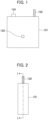
- Fig. 1 is an elevation view of a cartridge 101 included in an ion concentration measuring device 100 according to a first embodiment.
- the cartridge 101 includes an internal electrode 102, a flow path 103, and a communication line 104.
- the internal electrode 102 is an electrode for outputting a potential generated by an ion-sensitive membrane 105 described later.
- the flow path 103 is a through-hole through which a liquid sample passes.
- the communication line 104 is connected to a semiconductor memory 106 described later.
- a reading-writing unit 118 described later accesses the semiconductor memory 106 via the communication line 104 and writes or reads data.
- the communication line 104 is also used to supply power to the semiconductor memory 106.
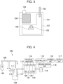
- Fig. 2 is a side view of the cartridge 101.
- a chain line I-I is a section line of Fig. 3 described later.
- the cartridge 101 can be configured using, for example, resin such as polyvinyl chloride, polystyrene, polypropylene, or the like.
- Fig. 3 is a cross-sectional view of the cartridge 101, taken along the chain line I-I of Fig. 2 .
- a cutout for enabling the liquid sample to flow out is formed in a portion of the flow path 103.
- the ion-sensitive membrane 105 is bonded to the flow path 103 to close the cutout.
- the ion-sensitive membrane 105 is configured so that electromotive force is generated depending on the type and concentration of ions within the sample.
- the ion-sensitive membrane 105 is constituted by resin such as polyvinyl chloride, polystyrene, polypropylene, or the like, a compound such as a ligand for supplementing ions, or the like.
- a plasticizer for plasticizing the ion-sensitive membrane 105, a highly fat-soluble ionic compound for removing an effect on ions, or the like may be used.
- a membrane of a type corresponding to an ion type to be measured is used.
- a sensitive membrane that responds to a sodium ion is used.
- potassium a sensitive membrane that responds to a potassium ion is used.
- the ion concentration measuring device for clinical inspection measures a sodium ion, a potassium ion, a chlorine ion, a calcium ion, a lithium ion, a phosphate ion, and the like in many cases.
- the first embodiment describes an example in which a sodium ion, a potassium ion, a chlorine ion are measured.
- the cartridge 101 is filled with internal gel 107.
- the internal electrode 102 is fixed so that the internal electrode 102 is in contact with the internal gel 107.
- the ion-sensitive membrane 105 contacts the sample and generates electromotive force depending on the concentration of ions within the sample. Since the ion-sensitive membrane 105 is electrically conductive with the internal electrode 102 via the internal gel 107, a change in the electromotive force of the ion-sensitive membrane 105 can be measured by measuring a potential output by the internal electrode 102. Therefore, the concentration of ions within the sample can be calculated.
- the semiconductor memory 106 is arranged on a portion separated from the internal gel 107 within the cartridge 101.
- the communication line 104 is connected to the semiconductor memory 106 and extends from the semiconductor memory 106 to the outside of the cartridge 101.
- Fig. 4 is a schematic configuration diagram of the ion concentration measuring device 100.
- a dilution tank 108 is provided to dilute the sample.
- a sample cup 130 holds the sample.
- a sample dispensing mechanism 109 dispenses the sample into the dilution tank 108.
- a dilution solution nozzle 110 discharges a dilution solution into the dilution tank 108.
- An internal reference solution nozzle 111 discharges an internal reference solution into the dilution tank 108.
- a sipper nozzle 112 sends the diluted sample and the internal reference solution from the dilution tank 108 to the flow path 103.
- An electrode installation unit 113 includes one or more cartridges that are the same as or similar to the cartridge 101.
- a reference potential cartridge 123 also has the same configuration and outputs a reference potential to be used to measure a potential difference.
- a potential measurer 114 measures differences between potentials output by the internal electrodes 102 of the cartridges and a reference potential output by the internal electrode 102 of the reference potential cartridge 123.
- a controller 115 controls units of the ion concentration measuring device 100 and uses results of measurement by the potential measurer 114 to calculate the concentration of ions within the sample.
- a storage unit 116 stores the results of the calculation.
- An output unit 117 outputs data stored in the storage unit 116.
- a reading-writing unit 118 writes data such as the calculation results received from the controller 115 to the semiconductor memories of the cartridges or reads data from the semiconductor memories 106.
- the internal electrodes 102 of the cartridges are connected to the potential measurer 114, and the communication lines 104 are connected to the reading-writing unit 118.
- the flow paths 103 are connected to the sipper nozzle 112.
- the sample aspirated from the sipper nozzle 112 is sent to the flow paths 103 of the cartridges.
- the cartridges are electrically conductive with each other via the sample.
- the potential measurer 114 measures potentials output by the internal electrodes 102 of the cartridges using the potential output by the reference potential cartridge 123 as a standard.
- the controller 115 supplies power to the semiconductor memories 106 in a time period excluding a time when the controller 115 acquires, from the potential measurer 114, the potentials output by the internal electrodes 102 of the cartridges. It is, therefore, possible to suppress effects of electrical noise generated from the semiconductor memories 106 and heat generated from the semiconductor memories 106 on results of the measurement based on the ion-sensitive membranes 105. A specific operational procedure is described using Fig. 5 described below.
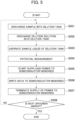
- Fig. 5 is a flowchart describing a procedure for measuring the concentration of ions within the sample by the ion concentration measuring device 100. Steps of Fig. 5 are described below.
- the sample dispensing mechanism 109 dispenses the sample within the sample cup 130 and discharges the sample into the dilution tank 108 (S501).
- the dilution solution nozzle 110 discharges the dilution solution into the dilution tank 108 to dilute the sample with the dilution solution (S502).
- the sipper nozzle 112 aspirates the sample solution within the dilution tank 108 and sends the sample to the flow paths 103. Therefore, the flow paths 103 of the cartridges are filled with the sample, and an electric circuit that connects the cartridges to the potential measurer 114 via the sample solution is formed.
- the potential measurer 114 uses the potential output by the reference potential cartridge 123 as a standard and measures potentials output by the internal electrodes 102 of the Na detection cartridge 120, the K detection cartridge 121, and the Cl detection cartridge 122.
- the controller 115 acquires the measurement results from the potential measurer 114 and uses the measurement results to calculate the concentration of ions within the sample.
- the controller 115 causes the calculation results to be stored in the storage unit 116.
- the controller 115 turns on power sources of the semiconductor memories 106 within the cartridges (or starts supplying power) (S505).
- the reading-writing unit 118 acquires the results of calculating the concentration of ions from the storage unit 116 and writes the results to the semiconductor memories of the cartridges (S506).
- the controller 115 turns off the power sources of the semiconductor memories 106 of the cartridges (or terminates the supply of power) (S507).
- the ion concentration measuring device 100 turns on the power sources of the semiconductor memories 106 in a time period excluding a time when the controller 115 acquires changes in the potentials generated by the ion-sensitive membranes 105. It is, therefore, possible to suppress effects of electric noise generated from the semiconductor memories 106 and heat generated from the semiconductor memories 106 on results of measuring the potentials. This can improve the accuracy of the measurement while an advantage of each of the ion-selective electrodes is used.
- the service life of the ion-sensitive membranes 105 is limited. Thus, after the ion-sensitive membranes 105 are used a certain number of times, the ion-sensitive membranes 105 need to be replaced. Since the cartridges 101 are attachable to and detachable from the ion concentration measuring device 100, the entire cartridges 101 can be replaced and thus are convenient. In addition, when the cartridges 101 are replaced, the semiconductor memories 106 included in the cartridges 101 can be recovered. A configuration in which the semiconductor memories 106 are installed in the cartridges 101 is useful from that point of view. On the other hand, conventionally, since an ion-sensitive membrane 105 is arranged in the vicinity of a semiconductor memory 106, an effect of electric noise or the like on a measurement result has been large. According to the first embodiment, it is possible to improve the accuracy of the measurement, while using the advantage that the semiconductor memories 106 are installed in the cartridges 101.
- Fig. 6 is a cross-sectional view of a cartridge 101 included in an ion concentration measuring device 100 according to a second embodiment.
- each of the cartridges 101 includes a temperature sensor 125 and a temperature control device 124, as well as the configurations described in the first embodiment. Since other configurations are the same as or similar to those described in the first embodiment, different features related to these devices are mainly described below.
- the temperature sensor 125 is a sensor for measuring the temperature of the ion-sensitive membrane 105. It is desirable that the temperature sensor 125 measure the temperature, for example, with accuracy of ⁇ 0.1°C in a range of 0°C to 50°C. The temperature sensor 125 does not necessarily need to be in contact with the ion-sensitive membrane 105. It is, however, desirable that the temperature sensor 125 be located in the vicinity of the ion-sensitive membrane 105 so that the temperature sensor 125 can measure at least a peripheral temperature around the ion-sensitive membrane 105.
- the temperature control device 124 is a device that cools the ion-sensitive membrane 105 heated with heat generated from the semiconductor memory 106 to a temperature at which the concentration of ions can be accurately measured. Since it is sufficient if the temperature control device 124 cools at least a peripheral region that is in thermal contact with the ion-sensitive membrane 105, the temperature control device 124 does not necessarily need to be in direct contact with the ion-sensitive membrane 105.
- the temperature control device 124 can be configured so that a flow path for a cooling medium is installed in the temperature control device 124 in the cartridge 101 and the cooling medium (for example, water, oil, or the like) is supplied from the outside of the cartridge 101.
- a thermoelectric element such as a Peltier element can be used.
- a cooling device and a heating device may be used.
- the controller 115 receives measurement results from the temperature sensors 125 via the communication lines 104 and turns on and off the supply of power to the temperature sensors 125 and the temperature control devices 124. Since electric and thermal noise is generated due to operations of the temperature sensors 125 and the temperature control devices 124 in a similar manner to the semiconductor memories 106, the controller 115 supplies power to the temperatures 125 and the temperature control devices 124 in a time period excluding a time when the controller 115 receives the results of the measurement based on the ion-sensitive membranes 105.
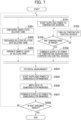
- Fig. 7 is a flowchart describing a procedure for measuring the concentration of ions within the sample by the ion concentration measuring device 100 according to the second embodiment.
- the ion concentration measuring device 100 performs steps S701 to S704 in parallel with steps S501 to S503 described with reference to Fig. 5 . Since other steps are the same as or similar to Fig. 5 , steps S701 to S704 are described below.
- the controller 115 starts supplying power to the temperature sensors 125.
- the temperature sensors 125 start measuring peripheral temperatures around the ion-sensitive membranes 105.
- the controller 115 acquires the measurement results.
- the procedure proceeds to step S704. Otherwise, the procedure proceeds to step S703.
- the temperature range in this step is determined based on necessary measurement accuracy. For example, it is desirable that the range is a range of ⁇ 1°C of a reference measurement temperature.
- the controller 115 supplies power to the temperature control devices 124 to cause the temperature control devices 124 to operate and adjust the peripheral temperatures around the ion-sensitive membranes 105 to a range (same range as that in step S702) suitable for the measurement. After this step, the procedure returns to step S702 to repeat the same processes.
- the controller 115 stops supplying power to the temperature sensors 125 (and the temperature control devices 124 when step S703 has been performed).
- the ion concentration measuring device 100 causes the temperature control devices 124 to adjust the peripheral temperatures around the ion-sensitive membranes 105 to a temperature suitable for the measurement. Therefore, for example, when amounts of heat generated from the semiconductor memories 106 are large and heat generated in the measurement of an initial specimen affects the measurement of a next specimen, or when heat generated from the semiconductor memories 106 is accumulated and the temperatures change during the time when a plurality of specimens are continuously measured, or the like, it is possible to reduce an effect on the measurement results.
- the second embodiment describes the case where the temperature control devices 124 adjust the peripheral temperatures around the ion-sensitive membranes 105 in accordance with the measurement results of the temperature sensors 125.
- the measurement results of the temperature sensors 125 can be used for other purposes.
- a third embodiment describes a specific example thereof.
- the ion-sensitive membrane 105 generally has a property varying depending on a temperature.
- characteristic data describing an association relationship between a potential generated by the ion-sensitive membrane 105 and the temperature of the ion-sensitive membrane 105 is stored in the storage unit 116 in advance and the controller 115 references the characteristic data and converts a potential output by the internal electrode 102 to the concentration of ions.
- the concentration of ions can be calculated by referencing the characteristic data using the difference between the reference potential and the measured potential and the result of the measurement by the temperature sensor 125.
- the peripheral temperature around the ion-sensitive membrane 105 is high and is not suitable for the measurement, and the semiconductor memory 106 is further heated, the peripheral temperature further deviates from the temperature suitable for the measurement. Therefore, it is considered that, in the case where the measurement result of the temperature sensor 125 exceeds the temperature suitable for the measurement of the ion-sensitive membrane 105, as the temperature is higher, the rate of writing to the semiconductor memory 106 is reduced. This is due to the fact that, when the writing rate is reduced, it is possible to suppress the generation of heat from the semiconductor memory 106.
- step S504 When the writing rate is reduced, there is a possibility that the writing is not completed in a time period up to the time when step S504 is performed next. In this case, remaining data that has not been completely written may be temporarily stored in the storage unit 116 and written again when step S506 is performed next.
- the first to third embodiments describe the example in which, in a time period excluding a time when the controller 115 acquires changes in the potentials generated by the ion-sensitive membranes 105, the controller 115 turns on the power sources of the semiconductor memories 106, and when the controller 115 acquires the changes in the potentials generated by the ion-sensitive membranes 105, the controller 115 turns off the power sources of the semiconductor memories 106.
- the controller 115 does not necessarily need to turn off the power sources of the semiconductor memories 106 when the controller 115 acquires the changes in the potentials.
- each of the semiconductor memories 106 and the controller 115 can have a normal mode and a standby mode.
- the normal mode is a mode in which power to be supplied to the semiconductor memories 106 is normal. Specifically, rated values are used as a supply voltage and an operation frequency, and high throughput can be obtained by using the functions of the semiconductor memories 106 and the functions of the controller 115 without a restriction.
- the standby mode is a mode in which power to be supplied to the semiconductor memories 106 is suppressed. Specifically, it is possible to suppress power consumption and reduce the occurrence of noise by any or a combination of methods that are a reduction in the supply voltage, a reduction in the operation frequency, the stop of an operation of a circuit block having a function other than a minimally necessary function (for example, a function necessary for hot start described later), and the like.
- the standby mode is referred to as sleep mode, power saving mode, idling mode, low-speed mode, low-voltage mode, temporal stop mode, or the like in some cases.
- the normal mode can be quickly activated, compared to the case where the normal mode is activated from a state in which the power sources are completely turned off (this is referred to as cold start or the like). This is due to the fact that, in the standby mode, a part of an initialization process or the entire initialization process can be omitted by holding at least a part of (or all of) information realizing a state in which the normal mode is activated in a static memory, a register, or the like.
- Combining the method, described in the first to third embodiments, of turning off the power sources of the semiconductor memories 106 when the controller 115 acquires the changes in the potentials with the standby mode described in the fourth embodiment can be regarded as the standby mode in a broad sense.
- the method of turning off the power sources can be considered as an extreme example of one of standby modes in a broad sense. This is due to the fact that turning off the power sources maximally suppresses power to be supplied to the semiconductor memories 106 and, in other words, reduces power to be supplied to zero.
- the invention is not limited to the foregoing embodiments of the invention and includes various modification examples.
- the foregoing embodiments of the invention are described in detail to clearly explain the invention and are not necessarily limited to all the configurations described.
- some of configurations described in a certain embodiment of the invention can be replaced with configurations described in another embodiment of the invention.
- a configuration described in a certain embodiment of the invention can be added to a configuration described in another embodiment of the invention.
- a configuration can be added to, removed from, or replaced with a part of the configurations of each of the embodiments of the invention.
- the foregoing embodiments describe the example in which the ion-sensitive membranes 105 are electrically connected to the internal electrodes 102 via the internal gel 107.
- a technique that does not use the internal gel 107 and is referred to as solid electrode may be used.
- a carbon fiber, metal such as silver, platinum, gold, or iron, or a conductive material such as an ion liquid is used to electrically conduct the ion-sensitive membranes 105 and the internal electrodes 102.
- the second embodiment describes the example in which the temperature sensor 125 and the temperature control device 124 are installed in each of the cartridges 101. This is due to the fact that it is desirable that these devices be arranged in the vicinity of the ion-sensitive membrane 105 to control the temperature. As long as equivalent functions can be realized, the temperature sensor 125 and the temperature control device 124 may be arranged outside each of the cartridges 101 as constituent elements of the ion concentration measuring device 100.
- the data to be written to the semiconductor memories 106 not only the results of calculating the concentration of ions but also data useful for analysis after the cartridges 101 are recovered can be written.
- the following items can be considered: (a) a time and date when the controller 115 calculates the concentration of ions or a time and date when the results of the calculation are written; (b) identifiers (manufacturing IDs or the like) of the ion-sensitive membranes 105 or the cartridges 101; (c) a manufacturing date of the ion-sensitive membranes 105 or the cartridges 101; (d) an expiration date of the ion-sensitive membranes 105 or the cartridges 101; (e) the results of calculating the concentration of ions by the controller 115 in a process of calibrating the cartridges 101; and (f) an alarm history (including an alarm occurrence time and date and the like) indicating that ion concentration calculated by the controller 115 is not in a reference range.
- the controller 115 and the reading-writing unit 118 can be configured using hardware such as a circuit device having the functions of these units or can be configured by causing an arithmetic device to execute software having the functions of these units.
- the storage unit 116 can be constituted by, for example, a storage device such as a hard disk device.
- Ion concentration measuring device 101 Cartridge 102: Internal electrode 103: Flow path 104: Communication line 105: Ion-sensitive membrane 106: Semiconductor memory 107: Internal gel 108: Dilution tank 109: Sample dispersing mechanism 110: Dilution solution nozzle 111: Internal reference solution nozzle 112: Sipper nozzle 113: Electrode installation unit 114: Potential measurer 115: Controller 116: Storage unit 117: Output unit 118: Reading-writing unit 119: Pump 120: Na detection cartridge 121: K detection cartridge 122: Cl detection cartridge 123: Reference potential cartridge 124: Temperature control device 125: Temperature sensor
Landscapes
- Health & Medical Sciences (AREA)
- Chemical & Material Sciences (AREA)
- Life Sciences & Earth Sciences (AREA)
- Physics & Mathematics (AREA)
- Analytical Chemistry (AREA)
- Biochemistry (AREA)
- General Health & Medical Sciences (AREA)
- General Physics & Mathematics (AREA)
- Immunology (AREA)
- Pathology (AREA)
- Engineering & Computer Science (AREA)
- Electrochemistry (AREA)
- Chemical Kinetics & Catalysis (AREA)
- Molecular Biology (AREA)
- Biomedical Technology (AREA)
- Biophysics (AREA)
- Databases & Information Systems (AREA)
- Medical Informatics (AREA)
- Optics & Photonics (AREA)
- Human Computer Interaction (AREA)
- Hematology (AREA)
- Urology & Nephrology (AREA)
- Food Science & Technology (AREA)
- Medicinal Chemistry (AREA)
- Automatic Analysis And Handling Materials Therefor (AREA)
- Spectroscopy & Molecular Physics (AREA)
Claims (11)
- Vorrichtung zur Messung einer Ionenkonzentration, die die Konzentration von in einer Lösung enthaltenen Ionen misst, umfassend:ein Ionendetektionselement (105) zur Erzeugung eines ersten Potentials auf der Grundlage der Konzentration;eine erste Elektrode (102) zur Ausgabe des ersten Potentials;einen Speicher (106) zum Speichern von Daten;ein Lese-/Schreibgerät (118) zum Schreiben von Daten in den Speicher oder zum Lesen von Daten aus dem Speicher; undeine Steuerung (115), die eingerichtet ist, das erste Potenzial zur Berechnung der Konzentration zu verwenden, wobeidas Ionendetektionselement (105) und der Speicher (106) in einer ersten Kassette (101) installiert sind,der Speicher (106) einen Normalmodus, in dem er mit normaler Energie versorgt wird, und einen Bereitschaftsmodus aufweist, in dem die Energieversorgung unterdrückt wird,die Steuerung (115) eingerichtet ist, den Speicher (106) in einer Speicherzugriffsperiode, die eine Potentialmessperiode ausschließt, für die die Steuerung einen Potentialwert erfasst, der dem von der ersten Elektrode (102) ausgegebenen ersten Potential entspricht, in den Normalmodus zu setzen, unddie Steuerung (115) eingerichtet ist, den Speicher (106) in den Bereitschaftsmodus zu setzen, wenn die Speicherzugriffsperiode abgeschlossen ist,dadurch gekennzeichnet, dass die Vorrichtung zur Messung der Ionenkonzentration weiterhin umfasst:einen Temperatursensor (125) zum Messen einer Umkreistemperatur um das Ionendetektionselement (105); undeine Temperatursteuervorrichtung (124), die eingerichtet ist, die Umkreistemperatur um das Ionendetektionselement (105) in Übereinstimmung mit dem Ergebnis der Detektion durch den Temperatursensor einzustellen, wobeidie Steuerung (115) eingerichtet ist, die Rate des Schreibens in den Speicher (106) zu reduzieren, wenn die von dem Temperatursensor (125) detektierte Umkreistemperatur um das Ionendetektionselement (105) eine für die Messung durch das Ionendetektionselement (105) geeignete Temperatur überschreitet, um die von dem Speicher beim Schreiben der Daten in den Speicher erzeugte Wärmemenge zu unterdrücken.
- Vorrichtung zur Messung einer Ionenkonzentration nach Anspruch 1, wobei
die Steuerung (115) eingerichtet ist, die Stromversorgung des Speichers (106) im Bereitschaftsmodus zu sperren. - Vorrichtung zur Messung einer Ionenkonzentration nach Anspruch 1, wobeidie Steuerung (115) eingerichtet ist, den Temperatursensor (125) und die Temperatursteuervorrichtung (124) in einer Temperatursteuerperiode, die die Potentialmessperiode ausschließt, mit Strom zu versorgen, unddie Steuerung (115) eingerichtet ist, die Stromversorgung des Temperatursensors (125) und der Temperatursteuervorrichtung (124) zu sperren, wenn die Temperatursteuerperiode abgeschlossen ist.
- Vorrichtung zur Messung einer Ionenkonzentration nach Anspruch 1, wobei
das Lese-Schreibgerät (118) eingerichtet ist, zumindest eines der folgenden Elemente in den Speicher (106) zu schreiben: ein Ergebnis der Berechnung der Konzentration, eine Uhrzeit und ein Datum, zu dem die Konzentration berechnet wurde, eine Kennung des Ionendetektionselements (105), ein Herstellungsdatum des Ionendetektionselements, ein Verfallsdatum des Ionendetektionselements, ein Ergebnis der Berechnung der Konzentration in einem Prozess der Kalibrierung des Ionendetektionselements und eine Alarmhistorie, die anzeigt, dass das Ergebnis der Berechnung der Konzentration nicht in einem Referenzbereich liegt. - Vorrichtung zur Messung einer Ionenkonzentration nach Anspruch 1, die ferner umfasst:eine Speichereinheit (116) zum Speichern charakteristischer Daten, die eine Assoziationsbeziehung zwischen einem von dem Ionendetektionselement (105) erzeugten Potential und einer Temperatur des Ionendetektionselements beschreiben, wobeidie Steuerung (115) eingerichtet ist, die Konzentration durch Bezugnahme auf die charakteristischen Daten unter Verwendung des Ergebnisses der Detektion durch den Temperatursensor (125) zu berechnen.
- Vorrichtung zur Messung einer Ionenkonzentration nach Anspruch 1, wobei
wenn Daten in der Speicherzugriffsperiode nicht vollständig in den Speicher (106) geschrieben werden, die Steuerung (115) eingerichtet ist, die nicht geschriebenen Daten vorübergehend zu halten, und wenn die nächste Speicherzugriffsperiode gekommen ist, die Steuerung eingerichtet ist, die nicht geschriebenen Daten in den Speicher zu schreiben. - Vorrichtung zur Messung einer Ionenkonzentration nach Anspruch 1, wobei
der Temperatursensor (125) und die Temperatursteuervorrichtung (124) in der ersten Kassette (101) installiert sind. - Vorrichtung zur Messung einer Ionenkonzentration nach Anspruch 1, wobeidie erste Kassette (101) weiterhin Gel (107) enthält, das in elektrischem Kontakt mit dem Ionendetektionselement (105) und der ersten Elektrode (102) steht, unddie erste Kassette (101) ein Durchgangsloch (103) aufweist, das die Lösung fließen lässt, um einen Fluidkontakt mit dem Ionendetektionselement (105) herzustellen.
- Vorrichtung zur Messung einer Ionenkonzentration nach Anspruch 1, wobei
die erste Kassette (101) so eingerichtet ist, dass sie am Rest der Vorrichtung zur Messung einer Ionenkonzentration angebracht und von ihr abgenommen werden kann. - Vorrichtung zur Messung einer Ionenkonzentration nach Anspruch 1, die ferner umfasst:eine zweite Kassette (123) mit einer zweiten Elektrode zur Ausgabe eines zweiten Potentials; undein Potentialmessgerät (114) zum Messen einer Potentialdifferenz zwischen dem ersten Potential und dem zweiten Potential, wobeidie Steuerung (115) eingerichtet ist, die Potenzialdifferenz zur Berechnung der Konzentration zu verwenden.
- Vorrichtung zur Messung einer Ionenkonzentration nach Anspruch 1, umfassend:eine Na-Ionen-Detektionskassette (120) mit einem Na-Ionen-Detektionselement zum Erzeugen eines Potentials auf der Grundlage der Konzentration von Na-Ionen;eine K-Ionen-Detektionskassette (121) mit einem K-Ionen-Detektionselement zum Erzeugen eines Potentials auf der Grundlage der Konzentration von K-Ionen; undeine Cl-Ionen-Detektionskassette (122) mit einem Cl-Ionen-Detektionselement zum Erzeugen eines Potentials auf der Grundlage der Konzentration von Cl-Ionen.
Applications Claiming Priority (2)
| Application Number | Priority Date | Filing Date | Title |
|---|---|---|---|
| JP2018039344 | 2018-03-06 | ||
| PCT/JP2019/003777 WO2019171852A1 (ja) | 2018-03-06 | 2019-02-04 | イオン濃度測定装置 |
Publications (3)
| Publication Number | Publication Date |
|---|---|
| EP3671197A1 EP3671197A1 (de) | 2020-06-24 |
| EP3671197A4 EP3671197A4 (de) | 2021-06-02 |
| EP3671197B1 true EP3671197B1 (de) | 2024-10-16 |
Family
ID=67847279
Family Applications (1)
| Application Number | Title | Priority Date | Filing Date |
|---|---|---|---|
| EP19764262.2A Active EP3671197B1 (de) | 2018-03-06 | 2019-02-04 | Ionenkonzentrationsmessvorrichtung |
Country Status (5)
| Country | Link |
|---|---|
| US (1) | US11397164B2 (de) |
| EP (1) | EP3671197B1 (de) |
| JP (1) | JP7106634B2 (de) |
| CN (1) | CN111480069B (de) |
| WO (1) | WO2019171852A1 (de) |
Families Citing this family (1)
| Publication number | Priority date | Publication date | Assignee | Title |
|---|---|---|---|---|
| CN120629267B (zh) * | 2025-06-26 | 2026-03-03 | 上海务宝机电科技有限公司 | 基于物联网的废酸再生用离子浓度在线监测设备及方法 |
Family Cites Families (17)
| Publication number | Priority date | Publication date | Assignee | Title |
|---|---|---|---|---|
| AT398132B (de) * | 1991-02-15 | 1994-09-26 | Avl Verbrennungskraft Messtech | Vorrichtung zur messung der konzentration eines reagens |
| US5453171A (en) * | 1992-03-10 | 1995-09-26 | The Board Of Regents Of The University Of Michigan | Heparin-selective polymeric membrane electrode |
| DE4228609C1 (de) * | 1992-08-28 | 1994-01-20 | Fraunhofer Ges Forschung | Vorrichtung zur Messung von Ionenkonzentrationen in Lösungen |
| GB9423435D0 (en) * | 1994-11-19 | 1995-01-11 | Belford Rona E | Solid state ion selective sensors: Conductimetric sensors using A.C. impedance and or admittance techniques as an alternative to potentiometric electrodes |
| KR100236175B1 (ko) * | 1995-12-29 | 1999-12-15 | 이구택 | 이온선택성 전극을 사용한 탈지공정의 알카리농도 자동측정및 제어방법 |
| US6743635B2 (en) * | 2002-04-25 | 2004-06-01 | Home Diagnostics, Inc. | System and methods for blood glucose sensing |
| NO317905B1 (no) * | 2002-09-11 | 2004-12-27 | Thin Film Electronics Asa | Fremgangsmate for a operere ferroelektrisk eller elektret minneinnretning og en innretning av denne art |
| JP2004191177A (ja) * | 2002-12-11 | 2004-07-08 | Materials & Energy Research Institute Tokyo Ltd | 水素化ホウ素イオン濃度の測定方法及び測定装置 |
| JP2007058593A (ja) * | 2005-08-24 | 2007-03-08 | Sharp Corp | 情報処理装置 |
| JP2007093252A (ja) * | 2005-09-27 | 2007-04-12 | Jokoh Co Ltd | 電解質分析装置の温調システム |
| JP5505420B2 (ja) | 2009-09-18 | 2014-05-28 | 日立化成株式会社 | イオン選択性電極カートリッジ |
| US20120177536A1 (en) * | 2009-09-18 | 2012-07-12 | Chiki Sakai | Automatic analyzer |
| US9127313B2 (en) * | 2009-12-01 | 2015-09-08 | Oxford Nanopore Technologies Limited | Biochemical analysis instrument |
| US8008087B1 (en) | 2010-03-25 | 2011-08-30 | Eci Technology, Inc. | Analysis of silicon concentration in phosphoric acid etchant solutions |
| CN104569112A (zh) * | 2015-01-06 | 2015-04-29 | 安徽科微智能科技有限公司 | 基于离子选择性电极的水质离子浓度连续在线检测方法 |
| JP6594431B2 (ja) | 2015-08-20 | 2019-10-23 | 株式会社日立ハイテクノロジーズ | イオン濃度測定装置 |
| US10488361B2 (en) * | 2016-08-26 | 2019-11-26 | Trividia Health, Inc. | Capacitive autocoding |
-
2019
- 2019-02-04 EP EP19764262.2A patent/EP3671197B1/de active Active
- 2019-02-04 CN CN201980004662.7A patent/CN111480069B/zh active Active
- 2019-02-04 JP JP2020504864A patent/JP7106634B2/ja active Active
- 2019-02-04 US US16/649,477 patent/US11397164B2/en active Active
- 2019-02-04 WO PCT/JP2019/003777 patent/WO2019171852A1/ja not_active Ceased
Also Published As
| Publication number | Publication date |
|---|---|
| JP7106634B2 (ja) | 2022-07-26 |
| JPWO2019171852A1 (ja) | 2021-04-15 |
| WO2019171852A1 (ja) | 2019-09-12 |
| CN111480069A (zh) | 2020-07-31 |
| EP3671197A4 (de) | 2021-06-02 |
| EP3671197A1 (de) | 2020-06-24 |
| US20200300809A1 (en) | 2020-09-24 |
| CN111480069B (zh) | 2022-10-18 |
| US11397164B2 (en) | 2022-07-26 |
Similar Documents
| Publication | Publication Date | Title |
|---|---|---|
| EP3803366B1 (de) | Ph-messung einer wässrigen probe | |
| CN105474003B (zh) | 气体浓度检测装置 | |
| JP6095862B2 (ja) | 腐食感知センサ、冷却装置、冷却システム及び車両用電源システム | |
| EP2225554B1 (de) | Ionische sonde mit mehreren elektroden | |
| US11714059B2 (en) | Isolating interferences in alkalinity measurement | |
| JP2022536720A (ja) | 毛細管制限型のセンサへの問い合わせ | |
| EP3859322B1 (de) | Messvorrichtung | |
| EP3671197B1 (de) | Ionenkonzentrationsmessvorrichtung | |
| US20140132274A1 (en) | Method and apparatus for providing information in an electrolyte measurment system | |
| JP2001108652A (ja) | 残留塩素濃度測定装置 | |
| JP5184877B2 (ja) | 電気化学半電池を監視する方法 | |
| JP2015095491A (ja) | 電子装置内における溶液濃度の監視方法とそのための液冷システム | |
| CN115032237A (zh) | 氧浓度计、氧浓度检测系统、氧化锆传感器电阻检测方法 | |
| US11959870B2 (en) | Differential probe with low-slope component | |
| CN204128998U (zh) | 用于检测尿液的检测器 |
Legal Events
| Date | Code | Title | Description |
|---|---|---|---|
| STAA | Information on the status of an ep patent application or granted ep patent |
Free format text: STATUS: THE INTERNATIONAL PUBLICATION HAS BEEN MADE |
|
| PUAI | Public reference made under article 153(3) epc to a published international application that has entered the european phase |
Free format text: ORIGINAL CODE: 0009012 |
|
| STAA | Information on the status of an ep patent application or granted ep patent |
Free format text: STATUS: REQUEST FOR EXAMINATION WAS MADE |
|
| 17P | Request for examination filed |
Effective date: 20200320 |
|
| AK | Designated contracting states |
Kind code of ref document: A1 Designated state(s): AL AT BE BG CH CY CZ DE DK EE ES FI FR GB GR HR HU IE IS IT LI LT LU LV MC MK MT NL NO PL PT RO RS SE SI SK SM TR |
|
| AX | Request for extension of the european patent |
Extension state: BA ME |
|
| A4 | Supplementary search report drawn up and despatched |
Effective date: 20210503 |
|
| RIC1 | Information provided on ipc code assigned before grant |
Ipc: G01N 27/28 20060101AFI20210427BHEP Ipc: G01N 27/416 20060101ALI20210427BHEP Ipc: G01N 33/487 20060101ALI20210427BHEP |
|
| DAV | Request for validation of the european patent (deleted) | ||
| DAX | Request for extension of the european patent (deleted) | ||
| STAA | Information on the status of an ep patent application or granted ep patent |
Free format text: STATUS: EXAMINATION IS IN PROGRESS |
|
| 17Q | First examination report despatched |
Effective date: 20221212 |
|
| GRAP | Despatch of communication of intention to grant a patent |
Free format text: ORIGINAL CODE: EPIDOSNIGR1 |
|
| STAA | Information on the status of an ep patent application or granted ep patent |
Free format text: STATUS: GRANT OF PATENT IS INTENDED |
|
| INTG | Intention to grant announced |
Effective date: 20240624 |
|
| GRAS | Grant fee paid |
Free format text: ORIGINAL CODE: EPIDOSNIGR3 |
|
| GRAA | (expected) grant |
Free format text: ORIGINAL CODE: 0009210 |
|
| STAA | Information on the status of an ep patent application or granted ep patent |
Free format text: STATUS: THE PATENT HAS BEEN GRANTED |
|
| AK | Designated contracting states |
Kind code of ref document: B1 Designated state(s): AL AT BE BG CH CY CZ DE DK EE ES FI FR GB GR HR HU IE IS IT LI LT LU LV MC MK MT NL NO PL PT RO RS SE SI SK SM TR |
|
| REG | Reference to a national code |
Ref country code: GB Ref legal event code: FG4D |
|
| RIN1 | Information on inventor provided before grant (corrected) |
Inventor name: IKEDA, UKYO Inventor name: OZAWA, SATOSHI Inventor name: ONO, TETSUYOSHI Inventor name: MIYAKE, MASAFUMI |
|
| REG | Reference to a national code |
Ref country code: CH Ref legal event code: EP |
|
| REG | Reference to a national code |
Ref country code: IE Ref legal event code: FG4D |
|
| REG | Reference to a national code |
Ref country code: DE Ref legal event code: R096 Ref document number: 602019060515 Country of ref document: DE |
|
| REG | Reference to a national code |
Ref country code: LT Ref legal event code: MG9D |
|
| REG | Reference to a national code |
Ref country code: NL Ref legal event code: MP Effective date: 20241016 |
|
| REG | Reference to a national code |
Ref country code: AT Ref legal event code: MK05 Ref document number: 1733297 Country of ref document: AT Kind code of ref document: T Effective date: 20241016 |
|
| PG25 | Lapsed in a contracting state [announced via postgrant information from national office to epo] |
Ref country code: NL Free format text: LAPSE BECAUSE OF FAILURE TO SUBMIT A TRANSLATION OF THE DESCRIPTION OR TO PAY THE FEE WITHIN THE PRESCRIBED TIME-LIMIT Effective date: 20241016 |
|
| PG25 | Lapsed in a contracting state [announced via postgrant information from national office to epo] |
Ref country code: NL Free format text: LAPSE BECAUSE OF FAILURE TO SUBMIT A TRANSLATION OF THE DESCRIPTION OR TO PAY THE FEE WITHIN THE PRESCRIBED TIME-LIMIT Effective date: 20241016 |
|
| PG25 | Lapsed in a contracting state [announced via postgrant information from national office to epo] |
Ref country code: HR Free format text: LAPSE BECAUSE OF FAILURE TO SUBMIT A TRANSLATION OF THE DESCRIPTION OR TO PAY THE FEE WITHIN THE PRESCRIBED TIME-LIMIT Effective date: 20241016 Ref country code: IS Free format text: LAPSE BECAUSE OF FAILURE TO SUBMIT A TRANSLATION OF THE DESCRIPTION OR TO PAY THE FEE WITHIN THE PRESCRIBED TIME-LIMIT Effective date: 20250216 Ref country code: PT Free format text: LAPSE BECAUSE OF FAILURE TO SUBMIT A TRANSLATION OF THE DESCRIPTION OR TO PAY THE FEE WITHIN THE PRESCRIBED TIME-LIMIT Effective date: 20250217 |
|
| PGFP | Annual fee paid to national office [announced via postgrant information from national office to epo] |
Ref country code: DE Payment date: 20250227 Year of fee payment: 7 |
|
| PG25 | Lapsed in a contracting state [announced via postgrant information from national office to epo] |
Ref country code: FI Free format text: LAPSE BECAUSE OF FAILURE TO SUBMIT A TRANSLATION OF THE DESCRIPTION OR TO PAY THE FEE WITHIN THE PRESCRIBED TIME-LIMIT Effective date: 20241016 |
|
| PG25 | Lapsed in a contracting state [announced via postgrant information from national office to epo] |
Ref country code: BG Free format text: LAPSE BECAUSE OF FAILURE TO SUBMIT A TRANSLATION OF THE DESCRIPTION OR TO PAY THE FEE WITHIN THE PRESCRIBED TIME-LIMIT Effective date: 20241016 |
|
| PG25 | Lapsed in a contracting state [announced via postgrant information from national office to epo] |
Ref country code: ES Free format text: LAPSE BECAUSE OF FAILURE TO SUBMIT A TRANSLATION OF THE DESCRIPTION OR TO PAY THE FEE WITHIN THE PRESCRIBED TIME-LIMIT Effective date: 20241016 |
|
| PG25 | Lapsed in a contracting state [announced via postgrant information from national office to epo] |
Ref country code: NO Free format text: LAPSE BECAUSE OF FAILURE TO SUBMIT A TRANSLATION OF THE DESCRIPTION OR TO PAY THE FEE WITHIN THE PRESCRIBED TIME-LIMIT Effective date: 20250116 |
|
| PG25 | Lapsed in a contracting state [announced via postgrant information from national office to epo] |
Ref country code: AT Free format text: LAPSE BECAUSE OF FAILURE TO SUBMIT A TRANSLATION OF THE DESCRIPTION OR TO PAY THE FEE WITHIN THE PRESCRIBED TIME-LIMIT Effective date: 20241016 Ref country code: GR Free format text: LAPSE BECAUSE OF FAILURE TO SUBMIT A TRANSLATION OF THE DESCRIPTION OR TO PAY THE FEE WITHIN THE PRESCRIBED TIME-LIMIT Effective date: 20250117 Ref country code: LV Free format text: LAPSE BECAUSE OF FAILURE TO SUBMIT A TRANSLATION OF THE DESCRIPTION OR TO PAY THE FEE WITHIN THE PRESCRIBED TIME-LIMIT Effective date: 20241016 |
|
| PG25 | Lapsed in a contracting state [announced via postgrant information from national office to epo] |
Ref country code: PL Free format text: LAPSE BECAUSE OF FAILURE TO SUBMIT A TRANSLATION OF THE DESCRIPTION OR TO PAY THE FEE WITHIN THE PRESCRIBED TIME-LIMIT Effective date: 20241016 |
|
| PGFP | Annual fee paid to national office [announced via postgrant information from national office to epo] |
Ref country code: FR Payment date: 20250224 Year of fee payment: 7 |
|
| PG25 | Lapsed in a contracting state [announced via postgrant information from national office to epo] |
Ref country code: RS Free format text: LAPSE BECAUSE OF FAILURE TO SUBMIT A TRANSLATION OF THE DESCRIPTION OR TO PAY THE FEE WITHIN THE PRESCRIBED TIME-LIMIT Effective date: 20250116 |
|
| PG25 | Lapsed in a contracting state [announced via postgrant information from national office to epo] |
Ref country code: SM Free format text: LAPSE BECAUSE OF FAILURE TO SUBMIT A TRANSLATION OF THE DESCRIPTION OR TO PAY THE FEE WITHIN THE PRESCRIBED TIME-LIMIT Effective date: 20241016 |
|
| PG25 | Lapsed in a contracting state [announced via postgrant information from national office to epo] |
Ref country code: DK Free format text: LAPSE BECAUSE OF FAILURE TO SUBMIT A TRANSLATION OF THE DESCRIPTION OR TO PAY THE FEE WITHIN THE PRESCRIBED TIME-LIMIT Effective date: 20241016 |
|
| REG | Reference to a national code |
Ref country code: DE Ref legal event code: R097 Ref document number: 602019060515 Country of ref document: DE |
|
| PG25 | Lapsed in a contracting state [announced via postgrant information from national office to epo] |
Ref country code: EE Free format text: LAPSE BECAUSE OF FAILURE TO SUBMIT A TRANSLATION OF THE DESCRIPTION OR TO PAY THE FEE WITHIN THE PRESCRIBED TIME-LIMIT Effective date: 20241016 |
|
| PG25 | Lapsed in a contracting state [announced via postgrant information from national office to epo] |
Ref country code: RO Free format text: LAPSE BECAUSE OF FAILURE TO SUBMIT A TRANSLATION OF THE DESCRIPTION OR TO PAY THE FEE WITHIN THE PRESCRIBED TIME-LIMIT Effective date: 20241016 |
|
| PG25 | Lapsed in a contracting state [announced via postgrant information from national office to epo] |
Ref country code: SK Free format text: LAPSE BECAUSE OF FAILURE TO SUBMIT A TRANSLATION OF THE DESCRIPTION OR TO PAY THE FEE WITHIN THE PRESCRIBED TIME-LIMIT Effective date: 20241016 |
|
| PG25 | Lapsed in a contracting state [announced via postgrant information from national office to epo] |
Ref country code: CZ Free format text: LAPSE BECAUSE OF FAILURE TO SUBMIT A TRANSLATION OF THE DESCRIPTION OR TO PAY THE FEE WITHIN THE PRESCRIBED TIME-LIMIT Effective date: 20241016 |
|
| PG25 | Lapsed in a contracting state [announced via postgrant information from national office to epo] |
Ref country code: IT Free format text: LAPSE BECAUSE OF FAILURE TO SUBMIT A TRANSLATION OF THE DESCRIPTION OR TO PAY THE FEE WITHIN THE PRESCRIBED TIME-LIMIT Effective date: 20241016 |
|
| PLBE | No opposition filed within time limit |
Free format text: ORIGINAL CODE: 0009261 |
|
| STAA | Information on the status of an ep patent application or granted ep patent |
Free format text: STATUS: NO OPPOSITION FILED WITHIN TIME LIMIT |
|
| PG25 | Lapsed in a contracting state [announced via postgrant information from national office to epo] |
Ref country code: SE Free format text: LAPSE BECAUSE OF FAILURE TO SUBMIT A TRANSLATION OF THE DESCRIPTION OR TO PAY THE FEE WITHIN THE PRESCRIBED TIME-LIMIT Effective date: 20241016 |
|
| PG25 | Lapsed in a contracting state [announced via postgrant information from national office to epo] |
Ref country code: MC Free format text: LAPSE BECAUSE OF FAILURE TO SUBMIT A TRANSLATION OF THE DESCRIPTION OR TO PAY THE FEE WITHIN THE PRESCRIBED TIME-LIMIT Effective date: 20241016 |
|
| 26N | No opposition filed |
Effective date: 20250717 |
|
| REG | Reference to a national code |
Ref country code: CH Ref legal event code: PL |
|
| PG25 | Lapsed in a contracting state [announced via postgrant information from national office to epo] |
Ref country code: LU Free format text: LAPSE BECAUSE OF NON-PAYMENT OF DUE FEES Effective date: 20250204 |
|
| PG25 | Lapsed in a contracting state [announced via postgrant information from national office to epo] |
Ref country code: CH Free format text: LAPSE BECAUSE OF NON-PAYMENT OF DUE FEES Effective date: 20250228 |
|
| GBPC | Gb: european patent ceased through non-payment of renewal fee |
Effective date: 20250204 |
|
| REG | Reference to a national code |
Ref country code: BE Ref legal event code: MM Effective date: 20250228 |
|
| PG25 | Lapsed in a contracting state [announced via postgrant information from national office to epo] |
Ref country code: GB Free format text: LAPSE BECAUSE OF NON-PAYMENT OF DUE FEES Effective date: 20250204 |
|
| PG25 | Lapsed in a contracting state [announced via postgrant information from national office to epo] |
Ref country code: BE Free format text: LAPSE BECAUSE OF NON-PAYMENT OF DUE FEES Effective date: 20250228 |
|
| PG25 | Lapsed in a contracting state [announced via postgrant information from national office to epo] |
Ref country code: IE Free format text: LAPSE BECAUSE OF NON-PAYMENT OF DUE FEES Effective date: 20250204 |