EP3670174A1 - Antifouling structure - Google Patents
Antifouling structure Download PDFInfo
- Publication number
- EP3670174A1 EP3670174A1 EP17922007.4A EP17922007A EP3670174A1 EP 3670174 A1 EP3670174 A1 EP 3670174A1 EP 17922007 A EP17922007 A EP 17922007A EP 3670174 A1 EP3670174 A1 EP 3670174A1
- Authority
- EP
- European Patent Office
- Prior art keywords
- porous structure
- structure layer
- micropores
- antifouling
- volatile liquid
- Prior art date
- Legal status (The legal status is an assumption and is not a legal conclusion. Google has not performed a legal analysis and makes no representation as to the accuracy of the status listed.)
- Withdrawn
Links
- 230000003373 anti-fouling effect Effects 0.000 title claims abstract description 64
- 239000007788 liquid Substances 0.000 claims abstract description 59
- YCKRFDGAMUMZLT-UHFFFAOYSA-N Fluorine atom Chemical compound [F] YCKRFDGAMUMZLT-UHFFFAOYSA-N 0.000 claims description 7
- 229910052731 fluorine Inorganic materials 0.000 claims description 7
- 239000011737 fluorine Substances 0.000 claims description 7
- 125000000524 functional group Chemical group 0.000 claims description 7
- 229920001296 polysiloxane Polymers 0.000 claims description 7
- 239000004215 Carbon black (E152) Substances 0.000 claims description 5
- 229930195733 hydrocarbon Natural products 0.000 claims description 5
- 150000002430 hydrocarbons Chemical class 0.000 claims description 5
- 125000000118 dimethyl group Chemical group [H]C([H])([H])* 0.000 claims description 3
- 229920001774 Perfluoroether Polymers 0.000 claims description 2
- UJMWVICAENGCRF-UHFFFAOYSA-N oxygen difluoride Chemical compound FOF UJMWVICAENGCRF-UHFFFAOYSA-N 0.000 claims description 2
- 230000000717 retained effect Effects 0.000 abstract description 3
- KFZMGEQAYNKOFK-UHFFFAOYSA-N Isopropanol Chemical compound CC(C)O KFZMGEQAYNKOFK-UHFFFAOYSA-N 0.000 description 33
- 230000000052 comparative effect Effects 0.000 description 23
- XLYOFNOQVPJJNP-UHFFFAOYSA-N water Substances O XLYOFNOQVPJJNP-UHFFFAOYSA-N 0.000 description 23
- 239000005361 soda-lime glass Substances 0.000 description 21
- VYPSYNLAJGMNEJ-UHFFFAOYSA-N Silicium dioxide Chemical compound O=[Si]=O VYPSYNLAJGMNEJ-UHFFFAOYSA-N 0.000 description 16
- 239000003607 modifier Substances 0.000 description 14
- 229920002545 silicone oil Polymers 0.000 description 14
- 239000000463 material Substances 0.000 description 13
- QAOWNCQODCNURD-UHFFFAOYSA-N Sulfuric acid Chemical compound OS(O)(=O)=O QAOWNCQODCNURD-UHFFFAOYSA-N 0.000 description 12
- 239000005871 repellent Substances 0.000 description 12
- 238000001035 drying Methods 0.000 description 11
- 239000003921 oil Substances 0.000 description 11
- 238000010992 reflux Methods 0.000 description 11
- 238000001878 scanning electron micrograph Methods 0.000 description 11
- 239000011800 void material Substances 0.000 description 11
- 238000000034 method Methods 0.000 description 7
- YXFVVABEGXRONW-UHFFFAOYSA-N Toluene Chemical compound CC1=CC=CC=C1 YXFVVABEGXRONW-UHFFFAOYSA-N 0.000 description 6
- 239000011248 coating agent Substances 0.000 description 6
- 238000000576 coating method Methods 0.000 description 6
- 229910010272 inorganic material Inorganic materials 0.000 description 6
- 239000011147 inorganic material Substances 0.000 description 6
- 238000002360 preparation method Methods 0.000 description 6
- 239000000377 silicon dioxide Substances 0.000 description 5
- 230000003746 surface roughness Effects 0.000 description 5
- ZIBGPFATKBEMQZ-UHFFFAOYSA-N triethylene glycol Chemical compound OCCOCCOCCO ZIBGPFATKBEMQZ-UHFFFAOYSA-N 0.000 description 5
- BOTDANWDWHJENH-UHFFFAOYSA-N Tetraethyl orthosilicate Chemical compound CCO[Si](OCC)(OCC)OCC BOTDANWDWHJENH-UHFFFAOYSA-N 0.000 description 4
- 238000005299 abrasion Methods 0.000 description 4
- 238000011156 evaluation Methods 0.000 description 4
- 238000010438 heat treatment Methods 0.000 description 4
- 230000014759 maintenance of location Effects 0.000 description 4
- 239000002245 particle Substances 0.000 description 4
- 229910052814 silicon oxide Inorganic materials 0.000 description 4
- 238000012360 testing method Methods 0.000 description 4
- 238000002834 transmittance Methods 0.000 description 4
- 239000006087 Silane Coupling Agent Substances 0.000 description 3
- 238000006243 chemical reaction Methods 0.000 description 3
- 239000003795 chemical substances by application Substances 0.000 description 3
- 125000004122 cyclic group Chemical group 0.000 description 3
- 239000011521 glass Substances 0.000 description 3
- 238000005259 measurement Methods 0.000 description 3
- 239000000203 mixture Substances 0.000 description 3
- 230000004048 modification Effects 0.000 description 3
- 238000012986 modification Methods 0.000 description 3
- 238000004528 spin coating Methods 0.000 description 3
- 238000007740 vapor deposition Methods 0.000 description 3
- GRYLNZFGIOXLOG-UHFFFAOYSA-N Nitric acid Chemical compound O[N+]([O-])=O GRYLNZFGIOXLOG-UHFFFAOYSA-N 0.000 description 2
- 230000009471 action Effects 0.000 description 2
- 230000001143 conditioned effect Effects 0.000 description 2
- 239000004205 dimethyl polysiloxane Substances 0.000 description 2
- 235000013870 dimethyl polysiloxane Nutrition 0.000 description 2
- 238000007654 immersion Methods 0.000 description 2
- 229910044991 metal oxide Inorganic materials 0.000 description 2
- 150000004706 metal oxides Chemical class 0.000 description 2
- 229910017604 nitric acid Inorganic materials 0.000 description 2
- 230000003287 optical effect Effects 0.000 description 2
- 229920000435 poly(dimethylsiloxane) Polymers 0.000 description 2
- 229910000077 silane Inorganic materials 0.000 description 2
- -1 silane compound Chemical class 0.000 description 2
- 239000002904 solvent Substances 0.000 description 2
- 244000020998 Acacia farnesiana Species 0.000 description 1
- IJGRMHOSHXDMSA-UHFFFAOYSA-N Atomic nitrogen Chemical compound N#N IJGRMHOSHXDMSA-UHFFFAOYSA-N 0.000 description 1
- 235000010643 Leucaena leucocephala Nutrition 0.000 description 1
- CDBYLPFSWZWCQE-UHFFFAOYSA-L Sodium Carbonate Chemical compound [Na+].[Na+].[O-]C([O-])=O CDBYLPFSWZWCQE-UHFFFAOYSA-L 0.000 description 1
- 125000000217 alkyl group Chemical group 0.000 description 1
- 230000015572 biosynthetic process Effects 0.000 description 1
- 239000005388 borosilicate glass Substances 0.000 description 1
- 125000003178 carboxy group Chemical group [H]OC(*)=O 0.000 description 1
- 230000008859 change Effects 0.000 description 1
- 238000004140 cleaning Methods 0.000 description 1
- 150000001875 compounds Chemical class 0.000 description 1
- NZZFYRREKKOMAT-UHFFFAOYSA-N diiodomethane Chemical compound ICI NZZFYRREKKOMAT-UHFFFAOYSA-N 0.000 description 1
- 238000003618 dip coating Methods 0.000 description 1
- 239000000428 dust Substances 0.000 description 1
- 230000000694 effects Effects 0.000 description 1
- 238000005516 engineering process Methods 0.000 description 1
- 238000001704 evaporation Methods 0.000 description 1
- 230000008020 evaporation Effects 0.000 description 1
- 239000004744 fabric Substances 0.000 description 1
- 125000001153 fluoro group Chemical group F* 0.000 description 1
- 239000007789 gas Substances 0.000 description 1
- 230000007062 hydrolysis Effects 0.000 description 1
- 238000006460 hydrolysis reaction Methods 0.000 description 1
- 238000010191 image analysis Methods 0.000 description 1
- QSHDDOUJBYECFT-UHFFFAOYSA-N mercury Chemical compound [Hg] QSHDDOUJBYECFT-UHFFFAOYSA-N 0.000 description 1
- 229910052753 mercury Inorganic materials 0.000 description 1
- LAQFLZHBVPULPL-UHFFFAOYSA-N methyl(phenyl)silicon Chemical compound C[Si]C1=CC=CC=C1 LAQFLZHBVPULPL-UHFFFAOYSA-N 0.000 description 1
- 239000003960 organic solvent Substances 0.000 description 1
- 239000010702 perfluoropolyether Substances 0.000 description 1
- 238000005191 phase separation Methods 0.000 description 1
- 238000006116 polymerization reaction Methods 0.000 description 1
- 238000002459 porosimetry Methods 0.000 description 1
- 230000009257 reactivity Effects 0.000 description 1
- 238000011160 research Methods 0.000 description 1
- 239000004576 sand Substances 0.000 description 1
- 238000003980 solgel method Methods 0.000 description 1
- 238000001179 sorption measurement Methods 0.000 description 1
- 238000005507 spraying Methods 0.000 description 1
- 230000007480 spreading Effects 0.000 description 1
- 238000003892 spreading Methods 0.000 description 1
- 238000003756 stirring Methods 0.000 description 1
- 239000000126 substance Substances 0.000 description 1
- 238000004804 winding Methods 0.000 description 1
Images


Classifications
-
- C—CHEMISTRY; METALLURGY
- C09—DYES; PAINTS; POLISHES; NATURAL RESINS; ADHESIVES; COMPOSITIONS NOT OTHERWISE PROVIDED FOR; APPLICATIONS OF MATERIALS NOT OTHERWISE PROVIDED FOR
- C09D—COATING COMPOSITIONS, e.g. PAINTS, VARNISHES OR LACQUERS; FILLING PASTES; CHEMICAL PAINT OR INK REMOVERS; INKS; CORRECTING FLUIDS; WOODSTAINS; PASTES OR SOLIDS FOR COLOURING OR PRINTING; USE OF MATERIALS THEREFOR
- C09D5/00—Coating compositions, e.g. paints, varnishes or lacquers, characterised by their physical nature or the effects produced; Filling pastes
-
- C—CHEMISTRY; METALLURGY
- C03—GLASS; MINERAL OR SLAG WOOL
- C03C—CHEMICAL COMPOSITION OF GLASSES, GLAZES OR VITREOUS ENAMELS; SURFACE TREATMENT OF GLASS; SURFACE TREATMENT OF FIBRES OR FILAMENTS MADE FROM GLASS, MINERALS OR SLAGS; JOINING GLASS TO GLASS OR OTHER MATERIALS
- C03C17/00—Surface treatment of glass, not in the form of fibres or filaments, by coating
- C03C17/006—Surface treatment of glass, not in the form of fibres or filaments, by coating with materials of composite character
- C03C17/008—Surface treatment of glass, not in the form of fibres or filaments, by coating with materials of composite character comprising a mixture of materials covered by two or more of the groups C03C17/02, C03C17/06, C03C17/22 and C03C17/28
- C03C17/009—Mixtures of organic and inorganic materials, e.g. ormosils and ormocers
-
- B—PERFORMING OPERATIONS; TRANSPORTING
- B32—LAYERED PRODUCTS
- B32B—LAYERED PRODUCTS, i.e. PRODUCTS BUILT-UP OF STRATA OF FLAT OR NON-FLAT, e.g. CELLULAR OR HONEYCOMB, FORM
- B32B5/00—Layered products characterised by the non- homogeneity or physical structure, i.e. comprising a fibrous, filamentary, particulate or foam layer; Layered products characterised by having a layer differing constitutionally or physically in different parts
- B32B5/18—Layered products characterised by the non- homogeneity or physical structure, i.e. comprising a fibrous, filamentary, particulate or foam layer; Layered products characterised by having a layer differing constitutionally or physically in different parts characterised by features of a layer of foamed material
-
- B—PERFORMING OPERATIONS; TRANSPORTING
- B60—VEHICLES IN GENERAL
- B60J—WINDOWS, WINDSCREENS, NON-FIXED ROOFS, DOORS, OR SIMILAR DEVICES FOR VEHICLES; REMOVABLE EXTERNAL PROTECTIVE COVERINGS SPECIALLY ADAPTED FOR VEHICLES
- B60J1/00—Windows; Windscreens; Accessories therefor
- B60J1/002—Windows; Windscreens; Accessories therefor with means for clear vision, e.g. anti-frost or defog panes, rain shields
-
- B—PERFORMING OPERATIONS; TRANSPORTING
- B60—VEHICLES IN GENERAL
- B60J—WINDOWS, WINDSCREENS, NON-FIXED ROOFS, DOORS, OR SIMILAR DEVICES FOR VEHICLES; REMOVABLE EXTERNAL PROTECTIVE COVERINGS SPECIALLY ADAPTED FOR VEHICLES
- B60J1/00—Windows; Windscreens; Accessories therefor
- B60J1/20—Accessories, e.g. wind deflectors, blinds
- B60J1/2094—Protective means for window, e.g. additional panel or foil, against vandalism, dirt, wear, shattered glass, etc.
-
- C—CHEMISTRY; METALLURGY
- C03—GLASS; MINERAL OR SLAG WOOL
- C03C—CHEMICAL COMPOSITION OF GLASSES, GLAZES OR VITREOUS ENAMELS; SURFACE TREATMENT OF GLASS; SURFACE TREATMENT OF FIBRES OR FILAMENTS MADE FROM GLASS, MINERALS OR SLAGS; JOINING GLASS TO GLASS OR OTHER MATERIALS
- C03C17/00—Surface treatment of glass, not in the form of fibres or filaments, by coating
- C03C17/28—Surface treatment of glass, not in the form of fibres or filaments, by coating with organic material
- C03C17/30—Surface treatment of glass, not in the form of fibres or filaments, by coating with organic material with silicon-containing compounds
-
- C—CHEMISTRY; METALLURGY
- C08—ORGANIC MACROMOLECULAR COMPOUNDS; THEIR PREPARATION OR CHEMICAL WORKING-UP; COMPOSITIONS BASED THEREON
- C08G—MACROMOLECULAR COMPOUNDS OBTAINED OTHERWISE THAN BY REACTIONS ONLY INVOLVING UNSATURATED CARBON-TO-CARBON BONDS
- C08G77/00—Macromolecular compounds obtained by reactions forming a linkage containing silicon with or without sulfur, nitrogen, oxygen or carbon in the main chain of the macromolecule
- C08G77/04—Polysiloxanes
- C08G77/22—Polysiloxanes containing silicon bound to organic groups containing atoms other than carbon, hydrogen and oxygen
- C08G77/24—Polysiloxanes containing silicon bound to organic groups containing atoms other than carbon, hydrogen and oxygen halogen-containing groups
-
- C—CHEMISTRY; METALLURGY
- C09—DYES; PAINTS; POLISHES; NATURAL RESINS; ADHESIVES; COMPOSITIONS NOT OTHERWISE PROVIDED FOR; APPLICATIONS OF MATERIALS NOT OTHERWISE PROVIDED FOR
- C09D—COATING COMPOSITIONS, e.g. PAINTS, VARNISHES OR LACQUERS; FILLING PASTES; CHEMICAL PAINT OR INK REMOVERS; INKS; CORRECTING FLUIDS; WOODSTAINS; PASTES OR SOLIDS FOR COLOURING OR PRINTING; USE OF MATERIALS THEREFOR
- C09D183/00—Coating compositions based on macromolecular compounds obtained by reactions forming in the main chain of the macromolecule a linkage containing silicon, with or without sulfur, nitrogen, oxygen, or carbon only; Coating compositions based on derivatives of such polymers
- C09D183/04—Polysiloxanes
- C09D183/08—Polysiloxanes containing silicon bound to organic groups containing atoms other than carbon, hydrogen, and oxygen
-
- B—PERFORMING OPERATIONS; TRANSPORTING
- B60—VEHICLES IN GENERAL
- B60J—WINDOWS, WINDSCREENS, NON-FIXED ROOFS, DOORS, OR SIMILAR DEVICES FOR VEHICLES; REMOVABLE EXTERNAL PROTECTIVE COVERINGS SPECIALLY ADAPTED FOR VEHICLES
- B60J1/00—Windows; Windscreens; Accessories therefor
-
- C—CHEMISTRY; METALLURGY
- C03—GLASS; MINERAL OR SLAG WOOL
- C03C—CHEMICAL COMPOSITION OF GLASSES, GLAZES OR VITREOUS ENAMELS; SURFACE TREATMENT OF GLASS; SURFACE TREATMENT OF FIBRES OR FILAMENTS MADE FROM GLASS, MINERALS OR SLAGS; JOINING GLASS TO GLASS OR OTHER MATERIALS
- C03C2217/00—Coatings on glass
- C03C2217/40—Coatings comprising at least one inhomogeneous layer
- C03C2217/425—Coatings comprising at least one inhomogeneous layer consisting of a porous layer
-
- C—CHEMISTRY; METALLURGY
- C03—GLASS; MINERAL OR SLAG WOOL
- C03C—CHEMICAL COMPOSITION OF GLASSES, GLAZES OR VITREOUS ENAMELS; SURFACE TREATMENT OF GLASS; SURFACE TREATMENT OF FIBRES OR FILAMENTS MADE FROM GLASS, MINERALS OR SLAGS; JOINING GLASS TO GLASS OR OTHER MATERIALS
- C03C2217/00—Coatings on glass
- C03C2217/40—Coatings comprising at least one inhomogeneous layer
- C03C2217/43—Coatings comprising at least one inhomogeneous layer consisting of a dispersed phase in a continuous phase
- C03C2217/46—Coatings comprising at least one inhomogeneous layer consisting of a dispersed phase in a continuous phase characterized by the dispersed phase
- C03C2217/47—Coatings comprising at least one inhomogeneous layer consisting of a dispersed phase in a continuous phase characterized by the dispersed phase consisting of a specific material
-
- C—CHEMISTRY; METALLURGY
- C03—GLASS; MINERAL OR SLAG WOOL
- C03C—CHEMICAL COMPOSITION OF GLASSES, GLAZES OR VITREOUS ENAMELS; SURFACE TREATMENT OF GLASS; SURFACE TREATMENT OF FIBRES OR FILAMENTS MADE FROM GLASS, MINERALS OR SLAGS; JOINING GLASS TO GLASS OR OTHER MATERIALS
- C03C2217/00—Coatings on glass
- C03C2217/40—Coatings comprising at least one inhomogeneous layer
- C03C2217/43—Coatings comprising at least one inhomogeneous layer consisting of a dispersed phase in a continuous phase
- C03C2217/46—Coatings comprising at least one inhomogeneous layer consisting of a dispersed phase in a continuous phase characterized by the dispersed phase
- C03C2217/48—Coatings comprising at least one inhomogeneous layer consisting of a dispersed phase in a continuous phase characterized by the dispersed phase having a specific function
-
- C—CHEMISTRY; METALLURGY
- C03—GLASS; MINERAL OR SLAG WOOL
- C03C—CHEMICAL COMPOSITION OF GLASSES, GLAZES OR VITREOUS ENAMELS; SURFACE TREATMENT OF GLASS; SURFACE TREATMENT OF FIBRES OR FILAMENTS MADE FROM GLASS, MINERALS OR SLAGS; JOINING GLASS TO GLASS OR OTHER MATERIALS
- C03C2217/00—Coatings on glass
- C03C2217/70—Properties of coatings
- C03C2217/76—Hydrophobic and oleophobic coatings
-
- C—CHEMISTRY; METALLURGY
- C03—GLASS; MINERAL OR SLAG WOOL
- C03C—CHEMICAL COMPOSITION OF GLASSES, GLAZES OR VITREOUS ENAMELS; SURFACE TREATMENT OF GLASS; SURFACE TREATMENT OF FIBRES OR FILAMENTS MADE FROM GLASS, MINERALS OR SLAGS; JOINING GLASS TO GLASS OR OTHER MATERIALS
- C03C2217/00—Coatings on glass
- C03C2217/70—Properties of coatings
- C03C2217/78—Coatings specially designed to be durable, e.g. scratch-resistant
-
- C—CHEMISTRY; METALLURGY
- C03—GLASS; MINERAL OR SLAG WOOL
- C03C—CHEMICAL COMPOSITION OF GLASSES, GLAZES OR VITREOUS ENAMELS; SURFACE TREATMENT OF GLASS; SURFACE TREATMENT OF FIBRES OR FILAMENTS MADE FROM GLASS, MINERALS OR SLAGS; JOINING GLASS TO GLASS OR OTHER MATERIALS
- C03C2218/00—Methods for coating glass
- C03C2218/10—Deposition methods
- C03C2218/11—Deposition methods from solutions or suspensions
- C03C2218/116—Deposition methods from solutions or suspensions by spin-coating, centrifugation
-
- G—PHYSICS
- G02—OPTICS
- G02B—OPTICAL ELEMENTS, SYSTEMS OR APPARATUS
- G02B1/00—Optical elements characterised by the material of which they are made; Optical coatings for optical elements
- G02B1/10—Optical coatings produced by application to, or surface treatment of, optical elements
- G02B1/18—Coatings for keeping optical surfaces clean, e.g. hydrophobic or photo-catalytic films
Definitions
- the present invention relates to an antifouling structure. More specifically, the present invention relates to an antifouling structure with improved durability.
- water-repellant articles which have a void layer with a void structure, void portions of the void layer being impregnated with a water-repellent material, is known.
- Patent Document 1 discloses a water-repellent article that is produced by forming a void layer having a void structure substantially made of an inorganic material and thereafter impregnating a void portion of the void layer with a water-repellent material.
- the water-repellent material oozes out of the interior of the void layer onto a surface region, even when the water-repellent material is damaged or removed. Therefore, high water repellency and high water slipperiness (water-droplet sliding property) can be maintained.
- Patent Document 1 WO 2008/120505A
- the void layer in the water-repellent article disclosed in Patent Literature 1 is produced by accumulating substantially spherical metal-oxide particles. Therefore, when a particle diameter of the metal oxide particles is increased to increase a voidage, an opening diameter of the voids is increased to reduce a capillary force. This makes it less likely to allow the water-repellent material to ooze out to the surface region. Therefore, an amount of the water-repellent material with which the void layer can be impregnated, and an amount of the water-repellent material that can be utilized are limited. This makes it difficult to maintain the water repellency for a long time.
- the present invention has been made in view of such problems in the art, and an object thereof is to provide a highly-durable antifouling structure that can sufficiently utilize a non-volatile liquid retained in a porous structure layer, and can exhibit antifouling property for a long time.
- An antifouling structure of the present invention is produced by impregnating a base having a porous structure layer including micropores with a non-volatile liquid.
- a relationship between an average opening diameter of the micropores and the number of the micropores per unit area of the porous structure layer satisfies the following formula (1).
- the porous structure layer includes the micropores that exhibit a sufficient capillary force, the retained non-volatile liquid can be sufficiently utilized.
- a highly-durable antifouling structure that exhibits antifouling property for a long time is thus provided.
- the antifouling structure includes a non-volatile liquid 2 and a porous structure layer 3 with micropores retaining the non-volatile liquid 2.
- a relationship between the number of micropores per unit area of the porous structure layer and an average opening diameter of the micropores satisfies the following formula (1). Average Opening Diameter nm ⁇ Number of Micropores / 100 nm 2 > 0.6 nm ⁇ 1
- a capillary force allows the non-volatile liquid 2 to ooze out of an inside of the porous structure layer 3 by an amount sufficient for covering a surface of the porous structure layer 3.
- the surface of the porous structure layer is thus covered with the non-volatile liquid to exhibit antifouling property for a long time.
- the antifouling structure since the antifouling structure has the large number of micropores with a small opening diameter, the capillary force is increased by the small opening diameter of the micropores to allow the non-volatile liquid to ooze out to the surface of the porous structure layer. Further, since the number of the micropores per unit area is large, an interval between the micropores which are adjacent to each other is small. Therefore, the surface of the porous structure layer can be covered with the non-volatile liquid that is oozed out by the capillary force.
- the porous structure layer 3 is, what is called, a sponge-like structure in which substantially spherical voids that are randomly disposed in three-dimensional directions communicate to each other to form the micropores.
- the porous structure layer 3 has affinity for the non-volatile liquid 2 (described later), and retains the non-volatile liquid 2 in the micropores.
- a structural material of the porous structure layer is randomly continuous in a mesh-like pattern in the three-dimensional directions, and the substantially spherical voids communicate to each other.
- a relationship between the shape of the voids and the shape of the structural material of this porous structure layer is an inverse of that of the porous structure layer formed by accumulating particles.
- the substantially spherical shape of the voids of the present invention is not limited to a spherical shape close to a perfect sphere, and may be a partially-recessed spherical shape, a spindle shape with a major diameter and a minor diameter that are significantly different from each other, or a winding bar shape.
- a relationship between the number of the micropores per unit area of the porous structure layer 3 and the average opening diameter of the micropores satisfy the following formula (2). Average Opening Diameter nm ⁇ Number of Micropores / 100 nm 2 > 0.75 nm ⁇ 1
- the porous structure layer 3 satisfies the formula (2), the capillary force is further increased, and the interval between the micropores which are adjacent to each other is reduced. This allows the surface to be wetted with the non-volatile liquid even when the non-volatile liquid to be used has low affinity for the porous structure layer.
- the number of the micropores per unit area was counted by photographing a range of ⁇ 3000 nm from above the surface of the porous structure layer with a scanning electron microscope (SEM), and detecting a micropore portion by binarizing an SEM image through image analysis in which -0.5 nm of an average line as a result of measurement of a surface roughness with an AFM was set as a threshold. Then, the number of the micropores per unit area was converted to the number of the micropores per ⁇ 10 nm.
- SEM scanning electron microscope
- a diameter of a circle with the same area as an area of an opening portion of each of the micropores was used as the average opening diameter, the area of the opening portion per one micropore being determined by dividing a sum of areas in the micropore portion in the range of ⁇ 3000 nm by the number of the micropores in the range of ⁇ 3000 nm.
- the micropores those which are so small as not allow entry of molecules of the non-volatile liquid do not contribute to the retention of the non-volatile liquid. Therefore, those micropores which are less than 10 nm are not considered in the determination of the number of the micropores and the average opening diameter.
- a difference in surface free energy between the porous structure layer and the non-volatile liquid is preferably 10 mJ/m 2 or less, more preferably 5 mJ/m 2 or less. When the difference in surface free energy is within these ranges, the porous structure layer is wetted with the non-volatile liquid, and the great capillary force is generated.
- the surface free energy of the porous structure layer which is influenced by the shape and a condition of the porous structure layer, can be calculated by the Cassie and Baxter method, the Owens and Wendt method, or the like, specifically, calculated from a contact angle, when water and diiodomethane is dropped on a smooth base.
- the porosity of the porous structure layer is preferably 4% to 60%, more preferably 4% to 45%, much more preferably 30% to 45%.
- both mechanical strength of the porous structure layer and a retention amount of the non-volatile liquid can be secured.
- the porosity is excessively low, the retention amount of the non-volatile liquid may decrease.
- the mechanical strength may decrease, which may collapse the voids to reduce the retention amount of the non-volatile liquid.
- the voids may excessively communicate to each other, which may increase the surface roughness to hinder the dirt from sliding off.
- the porosity can be measured, for example, by a gas adsorption method in which nitrogen (N 2 ) or the like is used, or mercury porosimetry.
- the surface roughness (Rz) of the porous structure layer is preferably 10 nm or less.
- Rz is 10 nm or less, the non-volatile liquid that oozes out of the inside of the porous structure layer by capillary action and the like covers the surface of the porous structure layer, and forms a smooth surface. This can prevent the porous structure layer from being exposed.
- An average film thickness (h) of the porous structure layer is preferably within a range of 50 nm to 1000 nm, more preferably within a range of 200 nm to 350 nm.
- the average film thickness of the porous structure layer is 50 nm or more, the porous structure layer can sufficiently retain the non-volatile liquid. This improves durability of the antifouling structure.
- the average film thickness is 1000 nm or less, formation of cracks due to volume shrinkage and the like can be prevented, when the porous structure layer is manufactured. This can prevent an increase of a haze value due to such cracks and the like, and thereby improve visibility.
- the porous structure layer is preferably made of a silicon oxide-based inorganic material.
- the porous structure layer is made of an inorganic material that contains silicon oxide with high degree of hardness, the porous structure layer has improved resistance to sliding abrasion. This improves the durability of the antifouling structure.
- the porous structure layer may be made of any inorganic material that has high optical transparency.
- examples of such materials include silica glass, soda glass, borosilicate glass, and the like that contain 60 wt% or more of silicon oxide (SiO 2 ).
- the surface of the porous structure layer and inner surfaces of the micropores are preferably modified with a modifier. Modification of the porous structure layer can reduce the surface energy of the porous structure layer. This allows the non-volatile liquid to sufficiently spread and wet the surface of the porous structure layer, and allows the non-volatile liquid to ooze out onto the surface of the porous structure layer by capillary action.
- Modifiers that can be used include modifiers that contain a compound having a functional group that can bind to the inorganic material of the porous structure layer.
- Silane coupling agents known in the art can be used as such modifiers.
- silane coupling agents include a silane compound having an alkoxyoligomeric structure with a hydrocarbon-based functional group, and a silane compound having an alkoxyoligomeric structure with a fluorine containing functional group.
- the non-volatile liquid 2 spreads and wets the surface of the porous structure layer 3 to form a smooth surface on an outermost surface of the antifouling structure 1.
- the non-volatile liquid 2 thereby repels dirt, such as water, oil, sand and dust, to reduce adhesion of such dirt.
- the silicone oils that can be used include straight-chain or cyclic silicone oils.
- straight-chain silicone oils include, what is called, straight silicone oils and modified silicone oils that have a molecular structure with dimethyl silicone as a main chain.
- straight silicone oils include dimethyl silicone oils and methylphenyl silicone oils.
- modified silicone oils include polyether-modified silicone oils, aralkyl-modified silicone oils and long-chain alkyl modified silicone oils.
- cyclic silicone oils include a cyclic dimetylsiloxane oil and the like.
- fluorinated oils examples include a fluoropolyether oil, a perfluoropolyether oil, and the like. It is preferred that the fluorinated oils have a molecular structure having perfluoroether as a main chain.
- the non-volatile liquid has a viscosity at 0°C of 160 mm 2 /s or less, more preferably within a range of 8 mm 2 /s to 80 mm 2 /s.
- the viscosity of the non-volatile liquid is 160 mm 2 /s or less, water repellency and the antifouling property can be improved.
- the viscosity is 8 mm 2 /s or more, the resistance to loss at high temperature can be improved.
- loss of the non-volatile liquid after heating at 120°C for 24 hours is less than 35 mass%.
- the loss on heating is 35 mass%, the antifouling structure can have high durability.
- the antifouling structure when used in automotive application, the performance is less likely to be deteriorated due to natural evaporation of the non-volatile liquid, and the antifouling structure can maintain good antifouling property at ambient temperature (5°C to 35°C) for a long time.
- the loss on heating can be determined by spreading 30 g of the non-volatile liquid on a 40 ⁇ petri dish, heating it at 120°C for 24 hours and measuring the loss.
- a base containing an inorganic material such as transparent glass can be used as the base 4 as the base 4.
- the porous structure layer is formed by a sol-gel method.
- the porous structure layer can be formed by changing a solution containing the material of the porous structure layer into a sol by hydrolysis and polymerization, applying the sol onto the base, or the like, allowing the reactions to further proceed to change the applied sol into a gel, drying and baking the gel, and modifying the surface and the inner surface of the micropores.
- the sol can be applied by a method known in the art such as spin coating, spraying, roll coating, flow coating or dip coating.
- the average opening diameter of the micropores can be adjusted by changing conditions of reactions at the time of forming the sol. Specifically, when an amount of water to be added is increased to allow the reactions to slowly proceed, silica components can be prevented from bonding to each other to eliminate the surface roughness and to thereby smooth the surface of the porous structure layer. Further, phase separation agents such as an organic solvent can be highly dispersed. This can reduce the average opening diameter.
- the surface of the porous structure layer can be modified by a method known in the art such as reflux, vapor deposition or immersion, and the surface is modified with the modifier such as the silane coupling agent. Thereafter, a part of the modifier, which do not contribute to the modification of the surface, is washed and removed. When the surplus of the modifier is removed, the modifier, which has reactivity, can be prevented from being mixed with the non-volatile liquid.
- the porous structure layer is impregnated with the non-volatile liquid such as silicone-based oil or fluorinated oil.
- the antifouling structure of the present invention can thus be produced.
- the antifouling structure has a parallel light transmittance (Tp) of 90% or more and a haze value (Hz) of 1% or less.
- Tp parallel light transmittance
- Hz haze value
- the parallel light transmittance can be measured by setting a sample film in a measurement device with an integrating sphere specified by JIS K7136, emitting light to the front side of the sample, and capturing the light that has penetrated the antifouling structure by using the integrating sphere.
- the haze value can be measured according to JIS K7136 with a haze/transmittance meter (Murakami Color Research Laboratory Co., Ltd.).
- the automobile part of the present invention includes the antifouling structure of the present invention.
- the automobile part With the antifouling structure, the automobile part can maintain high antifouling performance for a long time. This allows reducing the frequency of car wash or cleaning, and securing a good view under a circumstance of a rainy whether or a dirt road.
- automobile parts examples include camera lenses, mirrors, glass windows, painted surfaces of bodies and the like, various light covers, door handles, meter panels, window panels, radiator fins, evaporators, and the like.
- the automobile part is not limited thereto.
- the materials in the screw-top tube B were transferred to the screw-top tube A, and the mixture was stirred at 1500 rpm. After the temperature in the screw-top tube A reached 30°C (peak temperature), the mixture was further stirred for 30 minutes.
- the spin coating was carried out in the air conditioned at a temperature of 25°C and a humidity of 60%.
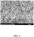
- the spin-coated soda lime glass was placed on a flat surface and dried with air for 2 minutes and then in a drying oven at 150°C for 1 hour. Then, the coated soda lime glass was allowed to cool down to room temperature in the drying oven. Thereafter, the coated soda lime glass was baked in a muffle furnace (FP410, Yamato Scientific Co., Ltd.) at 500°C for 1 hour and then allowed to cool down to room temperature in the muffle furnace. A porous structure layer A was thus formed on the soda lime glass base. An SEM image of the porous structure layer A is shown in FIG. 2 .
- a porous structure layer B was prepared in the same way as that for the porous structure layer A except charging the screw-top tube A with 0.92 g of pure water, 1.5 g of triethylene glycol, 0.78 g of isopropyl alcohol, and 0.3 g of sulfuric acid.
- An SEM image of the porous structure layer B is shown in FIG. 3 .
- a porous structure layer C was prepared in the same way as that for the porous structure layer A except charging the screw-top tube A with 0.64 g of pure water, 1.5 g of triethylene glycol, 0.78 g of isopropyl alcohol, and 0.3 g of sulfuric acid.
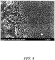
- An SEM image of the porous structure layer C is shown in FIG. 4 .
- a porous structure layer C was prepared in the same way as that for the porous structure layer A except charging the screw-top tube A with 0.56 g of pure water, 1.5 g of triethylene glycol, 0.78 g of isopropyl alcohol, and 1.0 g of sulfuric acid.
- An SEM image of the porous structure layer D is shown in FIG. 5 .
- a silica layer was prepared in the same way as that for the porous structure layer A except charging the screw-top tube A with 0.94 g of pure water, 0.78 g of isopropyl alcohol, and 0.3 g of sulfuric acid.
- the porous-structure-layer coating liquid was obtained in the same way as that for the porous structure layer A except charging the screw-top tube A with 1.04 g of pure water, 1.65 g of triethylene glycol, 0.78 g of isopropyl alcohol, and 0.2 g of sulfuric acid, and charging the screw-top tube B with 11.25 g of tetraethoxysilane (Tetr-thoxysilane, min. 98% TEOS: Wako Pure Chemical Corporation) and 0.78 g of isopropyl alcohol.
- the spin coating was carried out in the air conditioned at the temperature of 25°C and the humidity of 60%.
- the spin-coated soda lime glass was dried in the drying oven at 150°C for 1 hour. Then, the coated soda lime glass was allowed to cool down to room temperature in the drying oven. Thereafter, the coated soda lime glass was baked in the muffle furnace (FP410, Yamato Scientific Co., Ltd.) at 500°C for 1 hour and then allowed to cool down to room temperature in the muffle furnace. A porous structure layer E was thus formed on the soda lime glass base. An SEM image of the porous structure layer E is shown in FIG. 6 .
- the porous structure layer A with the modified surface was dried in the drying oven at 150°C for 1 hour and then allowed to cool down to room temperature in the drying oven. Thereafter, this porous structure layer A was soaked in toluene and washed with an ultrasonic cleaner (BAKUSEN W-113 Mk-II, Yamato Scientific Co., Ltd.) in a BAKUSEN mode (24 kHz and 31 kHz superimposed) for 5 minutes. Surface free energy at the time when the smooth base was modified with the hydrocarbon-based modifier was 23 mJ/m 2 .
- an ultrasonic cleaner BAKUSEN W-113 Mk-II, Yamato Scientific Co., Ltd.
- a non-volatile liquid dimethylpolysiloxane KF-96, Shin-Etsu Silicone Corp., viscosity of 100 mm 2 /sec, surface free energy of 23 mJ/m 2
- a non-volatile liquid dimethylpolysiloxane KF-96, Shin-Etsu Silicone Corp., viscosity of 100 mm 2 /sec, surface free energy of 23 mJ/m 2
- An antifouling structure was produced in the same way as that in Example 1 except using the porous structure layer B.
- An antifouling structure was produced in the same way as that in Example 1 except using the porous structure layer C.
- An antifouling structure was produced in the same way as that in Example 1 except using the porous structure layer D.
- a fluorine modifier (FLUOROSURF FG-5020, Fluoro Technology.) was refluxed at the temperature of 60°C for 2 hours to modify the surface of the porous structure layer A and the micropores therein.
- the porous structure layer A with the modified surface was dried in the drying oven at 150°C for 1 hour and then allowed to cool down to room temperature in the drying oven. Thereafter, this porous structure layer A was soaked in a fluorine solvent (NOVEC7100, 3M Corp.) and washed with the ultrasonic cleaner (BAKUSEN W-113 Mk-II, Yamato Scientific Co., Ltd.) in the BAKUSEN mode (24 kHz and 31 kHz superimposed) for 5 minutes.
- the surface free energy at the time when the smooth base was modified with the fluorine modifier was 11 mJ/m 2 .
- An antifouling structure was produced in the same way as that in Example 5 except using the porous structure layer B.
- An antifouling structure was produced in the same way as that in Example 5 except using the porous structure layer C.
- the soda lime glass with the modified surface was dried in the drying oven at 150°C for 1 hour and then allowed to cool down to room temperature in the drying oven. Thereafter, this soda lime glass was soaked in toluene and washed with the ultrasonic cleaner (BAKUSEN W-113 Mk-II, Yamato Scientific Co., Ltd.) in the BAKUSEN mode (24 kHz and 31 kHz superimposed) for 5 minutes.
- the ultrasonic cleaner BAKUSEN W-113 Mk-II, Yamato Scientific Co., Ltd.
- a non-volatile liquid (dimethylpolysiloxane KF-96, Shin-Etsu Silicone Corp.) was applied to the washed soda-lime glass, and the washed soda-lime glass was left in this state for 1 hour to be impregnated with the non-volatile liquid. An antifouling structure was thus produced.
- a non-volatile liquid dimethylpolysiloxane KF-96, Shin-Etsu Silicone Corp.
- An antifouling structure was produced in the same way as that in Example 1 except using the silica layer.
- An antifouling structure was produced in the same way as that in Example 1 except using the porous structure layer E.
- Vapor deposition of a fluorine water-repellent treatment agent was carried out on a soda lime glass, which was treated with plasma at the rate of 1 cm 2 /s by using the plasma generator, such that this agent was formed into a film with a film thickness of 10 nm. Further, this soda lime glass was soaked in the fluorine solvent (NOVEC7100, 3M Corp.) and washed with the ultrasonic cleaner (BAKUSEN W-113 Mk-II, Yamato Scientific Co., Ltd.) in the BAKUSEN mode (24 kHz and 31 kHz superimposed) for 5 minutes.
- the fluorine solvent NOVEC7100, 3M Corp.
- the ultrasonic cleaner BAKUSEN W-113 Mk-II, Yamato Scientific Co., Ltd.
- An antifouling structure was produced in the same way as that in Example 5 except using the porous structure layer E.
- Table 1 shows configuration features of the antifouling structures of Examples 1 to 7 and Comparative Examples 1 to 5.
- Table 1 (1/2) Porous Structure Layer Opening Diameter ⁇ Number of Micropores (nm-1) Average Opening Diameter (nm) Porosity (%) Surface Roughness RZ (nm) Film Thickness of Porous Structure Layer (nm)
- Example 1 A 0.75 48 30 5.67 313
- Example 2 B 1.12 35 4 5.7 300
- Example 5 A 0.75 48 30 5.67 313
- Example 6 B 1.12 35 4 5.7 300
- Comparative Example 4 Soda Lime Glass 0 N/A 0 3 - Comparative Example 5 E - - 65 5.96
- the droplet sliding property was evaluated by vertically placing each of the antifouling structures, dropping 5- ⁇ L droplets of water thereon, and measuring sliding speeds of these water droplets W.
- infrared sensors 5a and 5b were disposed at an interval of 15 mm, one being higher than the other.
- Five droplets at intervals of 5 mm in the horizontal direction were dropped at a droplet starting height D that was 5 mm above the upper infrared sensor. Sliding speeds of the five droplets at the time of advancing the interval of 15 mm were measured, and these speeds were averaged.
- Each of the antifouling structures was held at 90° for 4 hours in four cycles, and thereafter the water-droplet sliding property test was conducted.
Landscapes
- Chemical & Material Sciences (AREA)
- Engineering & Computer Science (AREA)
- Organic Chemistry (AREA)
- Chemical Kinetics & Catalysis (AREA)
- Life Sciences & Earth Sciences (AREA)
- Materials Engineering (AREA)
- Wood Science & Technology (AREA)
- General Chemical & Material Sciences (AREA)
- Geochemistry & Mineralogy (AREA)
- Physics & Mathematics (AREA)
- Mechanical Engineering (AREA)
- Polymers & Plastics (AREA)
- Health & Medical Sciences (AREA)
- Medicinal Chemistry (AREA)
- Inorganic Chemistry (AREA)
- General Physics & Mathematics (AREA)
- Optics & Photonics (AREA)
- Composite Materials (AREA)
- Laminated Bodies (AREA)
- Surface Treatment Of Glass (AREA)
- Surface Treatment Of Optical Elements (AREA)
- Materials Applied To Surfaces To Minimize Adherence Of Mist Or Water (AREA)
Abstract
Description
- The present invention relates to an antifouling structure. More specifically, the present invention relates to an antifouling structure with improved durability.
- Conventionally, water-repellant articles which have a void layer with a void structure, void portions of the void layer being impregnated with a water-repellent material, is known.
-
Patent Document 1 discloses a water-repellent article that is produced by forming a void layer having a void structure substantially made of an inorganic material and thereafter impregnating a void portion of the void layer with a water-repellent material. - According to the disclosure, since the interior of the voids of the water-repellent article is impregnated with the water-repellent material, the water-repellent material oozes out of the interior of the void layer onto a surface region, even when the water-repellent material is damaged or removed. Therefore, high water repellency and high water slipperiness (water-droplet sliding property) can be maintained.
- Patent Document 1:
WO 2008/120505A - However, the void layer in the water-repellent article disclosed in
Patent Literature 1 is produced by accumulating substantially spherical metal-oxide particles. Therefore, when a particle diameter of the metal oxide particles is increased to increase a voidage, an opening diameter of the voids is increased to reduce a capillary force. This makes it less likely to allow the water-repellent material to ooze out to the surface region.
Therefore, an amount of the water-repellent material with which the void layer can be impregnated, and an amount of the water-repellent material that can be utilized are limited. This makes it difficult to maintain the water repellency for a long time. - The present invention has been made in view of such problems in the art, and an object thereof is to provide a highly-durable antifouling structure that can sufficiently utilize a non-volatile liquid retained in a porous structure layer, and can exhibit antifouling property for a long time.
- An antifouling structure of the present invention is produced by impregnating a base having a porous structure layer including micropores with a non-volatile liquid. A relationship between an average opening diameter of the micropores and the number of the micropores per unit area of the porous structure layer satisfies the following formula (1).

- According to the present invention, since the porous structure layer includes the micropores that exhibit a sufficient capillary force, the retained non-volatile liquid can be sufficiently utilized. A highly-durable antifouling structure that exhibits antifouling property for a long time is thus provided.
-
-
FIG. 1 is a schematic cross-sectional view illustrating an example of an antifouling structure of the present invention. -
FIG. 2 is an SEM image of a porous structure layer A. -
FIG. 3 is an SEM image of a porous structure layer B. -
FIG. 4 is an SEM image of a porous structure layer C. -
FIG. 5 is an SEM image of a porous structure layer D. -
FIG. 6 is an SEM image of a porous structure layer E. -
FIG. 7 is an explanatory view illustrating a method of evaluating water-droplet sliding property. - An antifouling structure of the present invention will be described in detail. As illustrated in
FIG. 1 , the antifouling structure includes anon-volatile liquid 2 and aporous structure layer 3 with micropores retaining thenon-volatile liquid 2. A relationship between the number of micropores per unit area of the porous structure layer and an average opening diameter of the micropores satisfies the following formula (1).
- In the antifouling structure, a capillary force allows the
non-volatile liquid 2 to ooze out of an inside of theporous structure layer 3 by an amount sufficient for covering a surface of theporous structure layer 3. The surface of the porous structure layer is thus covered with the non-volatile liquid to exhibit antifouling property for a long time. - Specifically, since the antifouling structure has the large number of micropores with a small opening diameter, the capillary force is increased by the small opening diameter of the micropores to allow the non-volatile liquid to ooze out to the surface of the porous structure layer. Further, since the number of the micropores per unit area is large, an interval between the micropores which are adjacent to each other is small. Therefore, the surface of the porous structure layer can be covered with the non-volatile liquid that is oozed out by the capillary force.
- The
porous structure layer 3 is, what is called, a sponge-like structure in which substantially spherical voids that are randomly disposed in three-dimensional directions communicate to each other to form the micropores. Theporous structure layer 3 has affinity for the non-volatile liquid 2 (described later), and retains thenon-volatile liquid 2 in the micropores. - In the sponge-like structure, a structural material of the porous structure layer is randomly continuous in a mesh-like pattern in the three-dimensional directions, and the substantially spherical voids communicate to each other. A relationship between the shape of the voids and the shape of the structural material of this porous structure layer is an inverse of that of the porous structure layer formed by accumulating particles.
- Therefore, even when a porosity of the porous structure layer is increased, the opening diameter of the micropores is not increased. The capillary force that allows the non-volatile liquid to ooze out by the sufficient amount onto the surface is thus generated.
- The substantially spherical shape of the voids of the present invention is not limited to a spherical shape close to a perfect sphere, and may be a partially-recessed spherical shape, a spindle shape with a major diameter and a minor diameter that are significantly different from each other, or a winding bar shape.
- It is more preferred that a relationship between the number of the micropores per unit area of the
porous structure layer 3 and the average opening diameter of the micropores satisfy the following formula (2).
- When the
porous structure layer 3 satisfies the formula (2), the capillary force is further increased, and the interval between the micropores which are adjacent to each other is reduced. This allows the surface to be wetted with the non-volatile liquid even when the non-volatile liquid to be used has low affinity for the porous structure layer. - The number of the micropores per unit area was counted by photographing a range of □3000 nm from above the surface of the porous structure layer with a scanning electron microscope (SEM), and detecting a micropore portion by binarizing an SEM image through image analysis in which -0.5 nm of an average line as a result of measurement of a surface roughness with an AFM was set as a threshold. Then, the number of the micropores per unit area was converted to the number of the micropores per □10 nm.
A diameter of a circle with the same area as an area of an opening portion of each of the micropores was used as the average opening diameter, the area of the opening portion per one micropore being determined by dividing a sum of areas in the micropore portion in the range of □3000 nm by the number of the micropores in the range of □3000 nm. Among the micropores, those which are so small as not allow entry of molecules of the non-volatile liquid do not contribute to the retention of the non-volatile liquid. Therefore, those micropores which are less than 10 nm are not considered in the determination of the number of the micropores and the average opening diameter. - A difference in surface free energy between the porous structure layer and the non-volatile liquid is preferably 10 mJ/m2 or less, more preferably 5 mJ/m2 or less. When the difference in surface free energy is within these ranges, the porous structure layer is wetted with the non-volatile liquid, and the great capillary force is generated.
- The surface free energy of the porous structure layer, which is influenced by the shape and a condition of the porous structure layer, can be calculated by the Cassie and Baxter method, the Owens and Wendt method, or the like, specifically, calculated from a contact angle, when water and diiodomethane is dropped on a smooth base.
- The porosity of the porous structure layer is preferably 4% to 60%, more preferably 4% to 45%, much more preferably 30% to 45%.
- When the porosity is within these ranges, both mechanical strength of the porous structure layer and a retention amount of the non-volatile liquid can be secured. When the porosity is excessively low, the retention amount of the non-volatile liquid may decrease. When the porosity is excessively high, the mechanical strength may decrease, which may collapse the voids to reduce the retention amount of the non-volatile liquid. Further, the voids may excessively communicate to each other, which may increase the surface roughness to hinder the dirt from sliding off.
- The porosity can be measured, for example, by a gas adsorption method in which nitrogen (N2) or the like is used, or mercury porosimetry.
- The surface roughness (Rz) of the porous structure layer is preferably 10 nm or less.
When Rz is 10 nm or less, the non-volatile liquid that oozes out of the inside of the porous structure layer by capillary action and the like covers the surface of the porous structure layer, and forms a smooth surface. This can prevent the porous structure layer from being exposed. - An average film thickness (h) of the porous structure layer is preferably within a range of 50 nm to 1000 nm, more preferably within a range of 200 nm to 350 nm. When the average film thickness of the porous structure layer is 50 nm or more, the porous structure layer can sufficiently retain the non-volatile liquid. This improves durability of the antifouling structure.
When the average film thickness is 1000 nm or less, formation of cracks due to volume shrinkage and the like can be prevented, when the porous structure layer is manufactured. This can prevent an increase of a haze value due to such cracks and the like, and thereby improve visibility. - The porous structure layer is preferably made of a silicon oxide-based inorganic material. When the porous structure layer is made of an inorganic material that contains silicon oxide with high degree of hardness, the porous structure layer has improved resistance to sliding abrasion. This improves the durability of the antifouling structure.
- The porous structure layer may be made of any inorganic material that has high optical transparency. Examples of such materials include silica glass, soda glass, borosilicate glass, and the like that contain 60 wt% or more of silicon oxide (SiO2).
- The surface of the porous structure layer and inner surfaces of the micropores are preferably modified with a modifier.
Modification of the porous structure layer can reduce the surface energy of the porous structure layer. This allows the non-volatile liquid to sufficiently spread and wet the surface of the porous structure layer, and allows the non-volatile liquid to ooze out onto the surface of the porous structure layer by capillary action. - Modifiers that can be used include modifiers that contain a compound having a functional group that can bind to the inorganic material of the porous structure layer. Silane coupling agents known in the art can be used as such modifiers.
- Examples of such silane coupling agents include a silane compound having an alkoxyoligomeric structure with a hydrocarbon-based functional group, and a silane compound having an alkoxyoligomeric structure with a fluorine containing functional group.
- The
non-volatile liquid 2 spreads and wets the surface of theporous structure layer 3 to form a smooth surface on an outermost surface of theantifouling structure 1. Thenon-volatile liquid 2 thereby repels dirt, such as water, oil, sand and dust, to reduce adhesion of such dirt. - The non-volatile liquid that can be used include liquid with low surface energy, such as silicone oils and fluorinated oils. It is preferred that these oils are non-reactive oils that do not have a reactive functional group, such as -OH, -NH2, -COOH, -CH=CH- and -C=C-.
When the non-volatile liquid has a reactive functional group, the non-volatile liquid may react with the dirt to deteriorate antifouling property. - The silicone oils that can be used include straight-chain or cyclic silicone oils. Examples of straight-chain silicone oils include, what is called, straight silicone oils and modified silicone oils that have a molecular structure with dimethyl silicone as a main chain.
Examples of straight silicone oils include dimethyl silicone oils and methylphenyl silicone oils.
Examples of modified silicone oils include polyether-modified silicone oils, aralkyl-modified silicone oils and long-chain alkyl modified silicone oils.
Examples of cyclic silicone oils include a cyclic dimetylsiloxane oil and the like. - Examples of the fluorinated oils include a fluoropolyether oil, a perfluoropolyether oil, and the like. It is preferred that the fluorinated oils have a molecular structure having perfluoroether as a main chain.
- It is preferred that the non-volatile liquid has a viscosity at 0°C of 160 mm2/s or less, more preferably within a range of 8 mm2/s to 80 mm2/s.
- When the viscosity of the non-volatile liquid is 160 mm2/s or less, water repellency and the antifouling property can be improved. When the viscosity is 8 mm2/s or more, the resistance to loss at high temperature can be improved.
- Regarding the viscosity, it is preferred that loss of the non-volatile liquid after heating at 120°C for 24 hours is less than 35 mass%. When the loss on heating is 35 mass%, the antifouling structure can have high durability.
- For example, when the antifouling structure is used in automotive application, the performance is less likely to be deteriorated due to natural evaporation of the non-volatile liquid, and the antifouling structure can maintain good antifouling property at ambient temperature (5°C to 35°C) for a long time.
- The loss on heating can be determined by spreading 30 g of the non-volatile liquid on a 40ϕ petri dish, heating it at 120°C for 24 hours and measuring the loss.
- As the
base 4, a base containing an inorganic material such as transparent glass can be used. - To produce the antifouling structure of the present invention, as the first step, the porous structure layer is formed by a sol-gel method. Specifically, the porous structure layer can be formed by changing a solution containing the material of the porous structure layer into a sol by hydrolysis and polymerization, applying the sol onto the base, or the like, allowing the reactions to further proceed to change the applied sol into a gel, drying and baking the gel, and modifying the surface and the inner surface of the micropores.
- The sol can be applied by a method known in the art such as spin coating, spraying, roll coating, flow coating or dip coating.
- The average opening diameter of the micropores can be adjusted by changing conditions of reactions at the time of forming the sol. Specifically, when an amount of water to be added is increased to allow the reactions to slowly proceed, silica components can be prevented from bonding to each other to eliminate the surface roughness and to thereby smooth the surface of the porous structure layer. Further, phase separation agents such as an organic solvent can be highly dispersed. This can reduce the average opening diameter.
- The surface of the porous structure layer can be modified by a method known in the art such as reflux, vapor deposition or immersion, and the surface is modified with the modifier such as the silane coupling agent.
Thereafter, a part of the modifier, which do not contribute to the modification of the surface, is washed and removed. When the surplus of the modifier is removed, the modifier, which has reactivity, can be prevented from being mixed with the non-volatile liquid. - The porous structure layer is impregnated with the non-volatile liquid such as silicone-based oil or fluorinated oil. The antifouling structure of the present invention can thus be produced.
- It is preferred that the antifouling structure has a parallel light transmittance (Tp) of 90% or more and a haze value (Hz) of 1% or less. When the parallel light transmittance and the haze value are within these ranges, the antifouling structure satisfies transparency required for automobile parts, optical parts and the like.
- The parallel light transmittance can be measured by setting a sample film in a measurement device with an integrating sphere specified by JIS K7136, emitting light to the front side of the sample, and capturing the light that has penetrated the antifouling structure by using the integrating sphere.
The haze value can be measured according to JIS K7136 with a haze/transmittance meter (Murakami Color Research Laboratory Co., Ltd.). - The automobile part of the present invention includes the antifouling structure of the present invention. With the antifouling structure, the automobile part can maintain high antifouling performance for a long time. This allows reducing the frequency of car wash or cleaning, and securing a good view under a circumstance of a rainy whether or a dirt road.
- Examples of such automobile parts include camera lenses, mirrors, glass windows, painted surfaces of bodies and the like, various light covers, door handles, meter panels, window panels, radiator fins, evaporators, and the like. However, the automobile part is not limited thereto.
- Hereinafter, the present invention will be described in more detail by way of examples. However, the present invention is not limited to the following examples.
- A screw-top tube A charged with 0.68 g of pure water, 1.5 g of triethylene glycol, 0.78 g of isopropyl alcohol, and 0.3 g of sulfuric acid, and a screw-top tube B charged with 8.04 g of tetraethoxysilane (ethylsilicate 40, Colcoat Co., Ltd.), and 0.78 g of isopropyl alcohol were heated in a water bath maintained at 25°C.
- The materials in the screw-top tube B were transferred to the screw-top tube A, and the mixture was stirred at 1500 rpm. After the temperature in the screw-top tube A reached 30°C (peak temperature), the mixture was further stirred for 30 minutes.
- After the stirring, an aliquot (5.0 g) of the solution in the screw-top tube A was collected to a screw-top tube C. Then, 20 g of isopropyl alcohol was added thereto, and the mixture was stirred at 1500 rpm for 1 minute. A porous-structure-layer coating liquid was thus obtained.
- A soda lime glass (□100 mm), which was treated with plasma at a rate of 1 cm2/s by using a plasma generator, was spin-coated by an aliquot (1.5 ml) of the porous-structure-layer coating liquid by using a spin coater (K359D-1 SPINNER, Kyowa Rien Co., Ltd.) at a rotation speed of 100 rpm for 3 seconds, 500 rpm for 5 seconds, and then 1000 rpm for 15 seconds.
The spin coating was carried out in the air conditioned at a temperature of 25°C and a humidity of 60%. - The spin-coated soda lime glass was placed on a flat surface and dried with air for 2 minutes and then in a drying oven at 150°C for 1 hour. Then, the coated soda lime glass was allowed to cool down to room temperature in the drying oven. Thereafter, the coated soda lime glass was baked in a muffle furnace (FP410, Yamato Scientific Co., Ltd.) at 500°C for 1 hour and then allowed to cool down to room temperature in the muffle furnace. A porous structure layer A was thus formed on the soda lime glass base. An SEM image of the porous structure layer A is shown in
FIG. 2 . - A porous structure layer B was prepared in the same way as that for the porous structure layer A except charging the screw-top tube A with 0.92 g of pure water, 1.5 g of triethylene glycol, 0.78 g of isopropyl alcohol, and 0.3 g of sulfuric acid. An SEM image of the porous structure layer B is shown in
FIG. 3 . - A porous structure layer C was prepared in the same way as that for the porous structure layer A except charging the screw-top tube A with 0.64 g of pure water, 1.5 g of triethylene glycol, 0.78 g of isopropyl alcohol, and 0.3 g of sulfuric acid. An SEM image of the porous structure layer C is shown in
FIG. 4 . - A porous structure layer C was prepared in the same way as that for the porous structure layer A except charging the screw-top tube A with 0.56 g of pure water, 1.5 g of triethylene glycol, 0.78 g of isopropyl alcohol, and 1.0 g of sulfuric acid. An SEM image of the porous structure layer D is shown in
FIG. 5 . - A silica layer was prepared in the same way as that for the porous structure layer A except charging the screw-top tube A with 0.94 g of pure water, 0.78 g of isopropyl alcohol, and 0.3 g of sulfuric acid.
- The porous-structure-layer coating liquid was obtained in the same way as that for the porous structure layer A except charging the screw-top tube A with 1.04 g of pure water, 1.65 g of triethylene glycol, 0.78 g of isopropyl alcohol, and 0.2 g of sulfuric acid, and charging the screw-top tube B with 11.25 g of tetraethoxysilane (Tetr-thoxysilane, min. 98% TEOS: Wako Pure Chemical Corporation) and 0.78 g of isopropyl alcohol.
- A soda lime glass (□100 mm), which was treated with plasma at the rate of 1 cm2/s by using the plasma generator, was spin-coated by the aliquot (1.5 ml) of the porous-structure-layer coating liquid by using the spin coater (K359D-1 SPINNER, Kyowa Rien Co., Ltd.) at the rotation speed of 100 rpm for 3 seconds, 500 rpm for 5 seconds, and then 1000 rpm for 15 seconds.
The spin coating was carried out in the air conditioned at the temperature of 25°C and the humidity of 60%. - The spin-coated soda lime glass was dried in the drying oven at 150°C for 1 hour. Then, the coated soda lime glass was allowed to cool down to room temperature in the drying oven.
Thereafter, the coated soda lime glass was baked in the muffle furnace (FP410, Yamato Scientific Co., Ltd.) at 500°C for 1 hour and then allowed to cool down to room temperature in the muffle furnace. A porous structure layer E was thus formed on the soda lime glass base. An SEM image of the porous structure layer E is shown inFIG. 6 . - 0.37 g of a hydrocarbon-based modifier (KBM-3103C, Shin-Etsu Silicone Corp.), 0.14 g of 0.1% nitric acid, 0.26 g of pure water, and 50 g of isopropyl alcohol were refluxed at a temperature of 60°C for 2 hours to modify a surface of the porous structure layer A and micropores therein.
- The porous structure layer A with the modified surface was dried in the drying oven at 150°C for 1 hour and then allowed to cool down to room temperature in the drying oven. Thereafter, this porous structure layer A was soaked in toluene and washed with an ultrasonic cleaner (BAKUSEN W-113 Mk-II, Yamato Scientific Co., Ltd.) in a BAKUSEN mode (24 kHz and 31 kHz superimposed) for 5 minutes. Surface free energy at the time when the smooth base was modified with the hydrocarbon-based modifier was 23 mJ/m2.
- 0.006 g of a non-volatile liquid (dimethylpolysiloxane KF-96, Shin-Etsu Silicone Corp., viscosity of 100 mm2/sec, surface free energy of 23 mJ/m2) was applied to the washed porous structure layer A, and the washed porous structure layer A was left in this state for 1 hour to be impregnated with the non-volatile liquid. An antifouling structure was thus produced.
- An antifouling structure was produced in the same way as that in Example 1 except using the porous structure layer B.
- An antifouling structure was produced in the same way as that in Example 1 except using the porous structure layer C.
- An antifouling structure was produced in the same way as that in Example 1 except using the porous structure layer D.
- A fluorine modifier (FLUOROSURF FG-5020, Fluoro Technology.) was refluxed at the temperature of 60°C for 2 hours to modify the surface of the porous structure layer A and the micropores therein.
- The porous structure layer A with the modified surface was dried in the drying oven at 150°C for 1 hour and then allowed to cool down to room temperature in the drying oven. Thereafter, this porous structure layer A was soaked in a fluorine solvent (NOVEC7100, 3M Corp.) and washed with the ultrasonic cleaner (BAKUSEN W-113 Mk-II, Yamato Scientific Co., Ltd.) in the BAKUSEN mode (24 kHz and 31 kHz superimposed) for 5 minutes.
The surface free energy at the time when the smooth base was modified with the fluorine modifier was 11 mJ/m2. - 0.011 g of a non-volatile liquid (Krytox GPL103, DuPont Corp., viscosity of 80 mm2/sec, surface free energy of 17 mJ/m2) was applied to the porous structure layer A with the modified surface, and the porous structure layer A with the modified surface was left in this state for 1 hour to retain the non-volatile liquid. An antifouling structure was thus produced.
- An antifouling structure was produced in the same way as that in Example 5 except using the porous structure layer B.
- An antifouling structure was produced in the same way as that in Example 5 except using the porous structure layer C.
- 0.37 g of a hydrocarbon-based modifier (KBM-3063, Shin-Etsu Silicone Corp.), 0.14 g of 0.1% nitric acid, 0.26 g of pure water, and 50 g of isopropyl alcohol were refluxed at the temperature of 60°C for 1 hour to modify a surface of a soda lime glass, which was treated with plasma at the rate of 1 cm2/s by using the plasma generator.
- The soda lime glass with the modified surface was dried in the drying oven at 150°C for 1 hour and then allowed to cool down to room temperature in the drying oven. Thereafter, this soda lime glass was soaked in toluene and washed with the ultrasonic cleaner (BAKUSEN W-113 Mk-II, Yamato Scientific Co., Ltd.) in the BAKUSEN mode (24 kHz and 31 kHz superimposed) for 5 minutes.
- 0.006 g of a non-volatile liquid (dimethylpolysiloxane KF-96, Shin-Etsu Silicone Corp.) was applied to the washed soda-lime glass, and the washed soda-lime glass was left in this state for 1 hour to be impregnated with the non-volatile liquid. An antifouling structure was thus produced.
- An antifouling structure was produced in the same way as that in Example 1 except using the silica layer.
- An antifouling structure was produced in the same way as that in Example 1 except using the porous structure layer E.
- Vapor deposition of a fluorine water-repellent treatment agent (OPTOOL DSX) was carried out on a soda lime glass, which was treated with plasma at the rate of 1 cm2/s by using the plasma generator, such that this agent was formed into a film with a film thickness of 10 nm. Further, this soda lime glass was soaked in the fluorine solvent (NOVEC7100, 3M Corp.) and washed with the ultrasonic cleaner (BAKUSEN W-113 Mk-II, Yamato Scientific Co., Ltd.) in the BAKUSEN mode (24 kHz and 31 kHz superimposed) for 5 minutes.
- 0.011 g of the non-volatile liquid (Krytox GPL103, DuPont Corp.) was applied to the soda lime glass with a modified surface, and the soda lime glass with the modified surface was left in this state for 1 hour to retain the non-volatile liquid. An antifouling structure was thus produced.
- An antifouling structure was produced in the same way as that in Example 5 except using the porous structure layer E.
- Table 1 shows configuration features of the antifouling structures of Examples 1 to 7 and Comparative Examples 1 to 5.
Table 1 (1/2) Porous Structure Layer Opening Diameter × Number of Micropores (nm-1) Average Opening Diameter (nm) Porosity (%) Surface Roughness RZ (nm) Film Thickness of Porous Structure Layer (nm) Example 1 A 0.75 48 30 5.67 313 Example 2 B 1.12 35 4 5.7 300 Example 3 C 1.58 33 45 6.2 350 Example 4 D 0.6 54 60 3.18 248 Comparative Example 1 Soda Lime Glass 0 N/A 0 3 - Comparative Example 2 Silica Film 0 N/A 0 5 - Comparative Example 3 E - - 65 5.96 350 Example 5 A 0.75 48 30 5.67 313 Example 6 B 1.12 35 4 5.7 300 Example 7 C 1.58 33 45 6.2 350 Comparative Example 4 Soda Lime Glass 0 N/A 0 3 - Comparative Example 5 E - - 65 5.96 350 Modifier Modification Condition Non-volatile Liquid Viscosity (mm2/sec) Example 1 KBM-3103c Reflux KF-96 100 Example 2 KBM-3103c Reflux KF-96 100 Example 3 KBM-3103c Reflux KF-96 100 Example 4 KBM-3103c Reflux KF-96 100 Comparative Example 1 KBM-3063 Reflux KF-96 100 Comparative Example 2 KBM-3103c Reflux KF-96 100 Comparative Example 3 KBM-3103c Reflux KF-96 100 Example 5 FLUOROSURF FG-5020 Reflux K103 80 Example 6 FLUOROSURF FG-5020 Reflux K103 80 Example 7 FLUOROSURF FG-5020 Reflux K103 80 Comparative Example 4 OPTOOL DSX Vapor Deposition K103 80 Comparative Example 5 FLUOROSURF FG-5020 Immersion K103 80 - The antifouling structures of Examples 1 to 7 and Comparative Examples 1 to 5 were evaluated for heat resistance and abrasion resistance by a water-droplet sliding property test (described later). Tables 2 shows results of the evaluation.
- As illustrated in
FIG. 7 , the droplet sliding property was evaluated by vertically placing each of the antifouling structures, dropping 5-µL droplets of water thereon, and measuring sliding speeds of these water droplets W. - To measure the sliding speeds of the water droplets W,
infrared sensors - ⊚: The sliding speed of the water droplets was 5 mm/sec or more.
- ○: The sliding speed of the water droplets was more than 0 mm/sec and 5 mm/sec or less.
- ×: The sliding speed of the water droplets was 0 mm/sec.
- Each of the antifouling structures was held at 90° for 4 hours in four cycles, and thereafter the water-droplet sliding property test was conducted.
- A cloth (Toraysee, TORAY INDUSTRIES, INC.) was reciprocally slid 500 times against each of the antifouling structures, and thereafter the water-droplet sliding property test was conducted.
Table 2 Heat Resistance Abrasion Resistance Haze (%) Tt (%) Example 1 ⊚ ⊚ 0.1 93 Example 2 ○ ○ 0.2 93 Example 3 ⊚ ⊚ 0.5 93 Example 4 ○ ○ 0.2 93 Comparative Example 1 × × 0.1 92 Comparative Example 2 × × 0.2 93 Comparative Example 3 × × 0.4 92 Example 5 ⊚ ⊚ 0.1 93 Example 6 ⊚ ⊚ 0.1 93 Example 7 ⊚ ⊚ 0.4 94 Comparative Example 4 × × 0.1 93 Comparative Example 5 × × 0.4 94 -
- 1
- Antifouling structure
- 2
- Non-volatile liquid
- 3
- Porous structure layer
- 31
- Micropore
- 4
- Base
- 5a
- Infrared sensor
- 5b
- Infrared sensor
- 6
- Light source
- D
- Droplet starting height
- W
- Water droplet
- B
- Scale
Claims (11)
- An antifouling structure, in which a base having a porous structure layer is impregnated with a non-volatile liquid,
wherein a relationship between the number of micropores per unit area of the porous structure layer and an average opening diameter of the micropores satisfies the following formula (1):
- The antifouling structure according to claim 1, wherein the relationship between the number of the micropores per unit area of the porous structure layer and the average opening diameter of the micropores satisfies the following formula (2):

- The antifouling structure according to claim 1 or 2, wherein the porosity of the porous structure layer is 4% to 60%.
- The antifouling structure according to claim 1 or 2, wherein the porosity of the porous structure layer is 4% to 45%.
- The antifouling structure according to claim 1 or 2, wherein the porosity of the porous structure layer is 30% to 45%.
- The antifouling structure according to any one of claims 1 to 5, wherein a surface of the porous structure layer and an inner surface of the micropores are modified with alkoxyoligomer having a hydrocarbon-based functional group.
- The antifouling structure according to claim 6, wherein the non-volatile liquid has a molecular structure with dimethyl silicone in a main chain.
- The antifouling structure according to any one of claims 1 to 5, wherein the surface of the porous structure layer and the inner surface of the micropores are modified with alkoxyoligomer having a fluorine containing functional group.
- The antifouling structure according to claim 8, wherein the non-volatile liquid has a molecular structure having perfluoroether in a main chain.
- The antifouling structure according to any one of claims 1 to 9, wherein, in the porous structure layer, substantially spherical voids that are randomly disposed in three-dimensional directions communicate to each other to form the micropores.
- The antifouling structure according to any one of claims 1 to 10, wherein a difference in surface free energy between the porous structure layer and the non-volatile liquid is 10 mJ/m2 or less.
Applications Claiming Priority (1)
| Application Number | Priority Date | Filing Date | Title |
|---|---|---|---|
| PCT/JP2017/029477 WO2019035192A1 (en) | 2017-08-16 | 2017-08-16 | Antifouling structure |
Publications (2)
| Publication Number | Publication Date |
|---|---|
| EP3670174A1 true EP3670174A1 (en) | 2020-06-24 |
| EP3670174A4 EP3670174A4 (en) | 2020-08-19 |
Family
ID=65362520
Family Applications (1)
| Application Number | Title | Priority Date | Filing Date |
|---|---|---|---|
| EP17922007.4A Withdrawn EP3670174A4 (en) | 2017-08-16 | 2017-08-16 | Antifouling structure |
Country Status (5)
| Country | Link |
|---|---|
| US (1) | US20200181418A1 (en) |
| EP (1) | EP3670174A4 (en) |
| JP (1) | JP6896234B2 (en) |
| CN (1) | CN110831757A (en) |
| WO (1) | WO2019035192A1 (en) |
Families Citing this family (3)
| Publication number | Priority date | Publication date | Assignee | Title |
|---|---|---|---|---|
| JP7389259B2 (en) * | 2020-07-13 | 2023-11-29 | 日東電工株式会社 | Optical film with antifouling layer |
| JP7514751B2 (en) * | 2020-12-14 | 2024-07-11 | 日産自動車株式会社 | Antifouling structure and automobile part having the same |
| JP7762443B2 (en) * | 2021-08-30 | 2025-10-30 | 国立大学法人北海道大学 | Laminate and method for manufacturing laminate |
Family Cites Families (16)
| Publication number | Priority date | Publication date | Assignee | Title |
|---|---|---|---|---|
| KR100391062B1 (en) * | 2000-03-17 | 2003-09-17 | 가부시기가이샤 이낙스 | Structure having hydrophilic fine porous antifouling layer and coating solution for forming said antifouling layer, and method for manufacturing said structure |
| JP2005112911A (en) * | 2003-10-03 | 2005-04-28 | Matsushita Electric Works Ltd | Defogging and soilproof material and its manufacturing process |
| DE102005020168A1 (en) * | 2005-04-28 | 2006-11-02 | Schott Ag | Coating glass or ceramic substrate with anti-reflective layer using sol-gel process, employs e.g. silicon-aluminum mixed oxide with adsorbed hydrophobe present in sol-gel binder |
| JP2008008997A (en) * | 2006-06-27 | 2008-01-17 | Bridgestone Kbg Co Ltd | Composite sound absorbing structural body |
| JPWO2008120505A1 (en) | 2007-03-29 | 2010-07-15 | コニカミノルタホールディングス株式会社 | Water repellent articles, architectural window glass and vehicle window glass |
| WO2009066630A1 (en) * | 2007-11-19 | 2009-05-28 | Konica Minolta Holdings, Inc. | Water-repellent or antifouling article and window glass for building, window glass for vehicle, display member, and optical part all employing the same |
| JP2014079920A (en) * | 2012-10-15 | 2014-05-08 | Asahi Glass Co Ltd | Article and production method of the same |
| US20140314991A1 (en) * | 2013-03-15 | 2014-10-23 | LiquiGlide Inc. | Methods and articles for liquid-impregnated surfaces for the inhibition of vapor or gas nucleation |
| JP6171788B2 (en) * | 2013-09-25 | 2017-08-02 | 日産自動車株式会社 | Antifouling body and method for producing the same |
| JP6171801B2 (en) * | 2013-09-30 | 2017-08-02 | 日産自動車株式会社 | Antifouling body and method for producing the same |
| US20150179321A1 (en) * | 2013-12-20 | 2015-06-25 | Massachusetts Institute Of Technology | Controlled liquid/solid mobility using external fields on lubricant-impregnated surfaces |
| US20150273518A1 (en) * | 2014-03-25 | 2015-10-01 | Liquiglide, Inc. | Spray Processes and Methods for Forming Liquid-Impregnated Surfaces |
| WO2015145703A1 (en) * | 2014-03-27 | 2015-10-01 | 日産自動車株式会社 | Anti-fouling surface structure and motor vehicle component |
| WO2015155830A1 (en) * | 2014-04-08 | 2015-10-15 | 日産自動車株式会社 | High durability anti-fouling structure and car part using same |
| JP6515696B2 (en) * | 2015-06-16 | 2019-05-22 | 日産自動車株式会社 | Method of manufacturing antifouling structure |
| CN107848255A (en) * | 2015-07-17 | 2018-03-27 | 日产自动车株式会社 | Anti-pollution structure body and its manufacture method |
-
2017
- 2017-08-16 JP JP2019536387A patent/JP6896234B2/en active Active
- 2017-08-16 EP EP17922007.4A patent/EP3670174A4/en not_active Withdrawn
- 2017-08-16 WO PCT/JP2017/029477 patent/WO2019035192A1/en not_active Ceased
- 2017-08-16 CN CN201780092810.6A patent/CN110831757A/en active Pending
- 2017-08-16 US US16/638,937 patent/US20200181418A1/en not_active Abandoned
Also Published As
| Publication number | Publication date |
|---|---|
| US20200181418A1 (en) | 2020-06-11 |
| CN110831757A (en) | 2020-02-21 |
| JPWO2019035192A1 (en) | 2020-05-28 |
| JP6896234B2 (en) | 2021-06-30 |
| WO2019035192A1 (en) | 2019-02-21 |
| EP3670174A4 (en) | 2020-08-19 |
Similar Documents
| Publication | Publication Date | Title |
|---|---|---|
| JP6171788B2 (en) | Antifouling body and method for producing the same | |
| JP6635115B2 (en) | Antifouling structure and method of manufacturing the same | |
| EP3670174A1 (en) | Antifouling structure | |
| EP3470222B1 (en) | Antifouling structure and automotive component using antifouling structure | |
| EP3459728B1 (en) | Soil-resistant structure and automobile component provided with said soil-resistant structure | |
| EP3513962B1 (en) | Antifouling structure | |
| CN110944832B (en) | Antifouling structure and automobile part provided with the antifouling structure | |
| KR100216869B1 (en) | Water-repellent glass having excellent durability and a method of manufacturing the same |
Legal Events
| Date | Code | Title | Description |
|---|---|---|---|
| STAA | Information on the status of an ep patent application or granted ep patent |
Free format text: STATUS: THE INTERNATIONAL PUBLICATION HAS BEEN MADE |
|
| PUAI | Public reference made under article 153(3) epc to a published international application that has entered the european phase |
Free format text: ORIGINAL CODE: 0009012 |
|
| STAA | Information on the status of an ep patent application or granted ep patent |
Free format text: STATUS: REQUEST FOR EXAMINATION WAS MADE |
|
| 17P | Request for examination filed |
Effective date: 20200121 |
|
| AK | Designated contracting states |
Kind code of ref document: A1 Designated state(s): AL AT BE BG CH CY CZ DE DK EE ES FI FR GB GR HR HU IE IS IT LI LT LU LV MC MK MT NL NO PL PT RO RS SE SI SK SM TR |
|
| AX | Request for extension of the european patent |
Extension state: BA ME |
|
| A4 | Supplementary search report drawn up and despatched |
Effective date: 20200720 |
|
| RIC1 | Information provided on ipc code assigned before grant |
Ipc: B60J 1/00 20060101ALI20200714BHEP Ipc: B32B 5/18 20060101AFI20200714BHEP Ipc: C09K 3/18 20060101ALI20200714BHEP Ipc: C03C 17/00 20060101ALI20200714BHEP Ipc: G02B 1/18 20150101ALI20200714BHEP |
|
| DAV | Request for validation of the european patent (deleted) | ||
| DAX | Request for extension of the european patent (deleted) | ||
| STAA | Information on the status of an ep patent application or granted ep patent |
Free format text: STATUS: THE APPLICATION HAS BEEN WITHDRAWN |
|
| 18W | Application withdrawn |
Effective date: 20220224 |