EP3670138A1 - Maschine zum umspritzen einer dichtung an einem tank aus kunststoffmaterial - Google Patents
Maschine zum umspritzen einer dichtung an einem tank aus kunststoffmaterial Download PDFInfo
- Publication number
- EP3670138A1 EP3670138A1 EP19217677.4A EP19217677A EP3670138A1 EP 3670138 A1 EP3670138 A1 EP 3670138A1 EP 19217677 A EP19217677 A EP 19217677A EP 3670138 A1 EP3670138 A1 EP 3670138A1
- Authority
- EP
- European Patent Office
- Prior art keywords
- tank
- carriages
- axis
- molding part
- plastic material
- Prior art date
- Legal status (The legal status is an assumption and is not a legal conclusion. Google has not performed a legal analysis and makes no representation as to the accuracy of the status listed.)
- Granted
Links
Images


Classifications
-
- B—PERFORMING OPERATIONS; TRANSPORTING
- B29—WORKING OF PLASTICS; WORKING OF SUBSTANCES IN A PLASTIC STATE IN GENERAL
- B29C—SHAPING OR JOINING OF PLASTICS; SHAPING OF MATERIAL IN A PLASTIC STATE, NOT OTHERWISE PROVIDED FOR; AFTER-TREATMENT OF THE SHAPED PRODUCTS, e.g. REPAIRING
- B29C45/00—Injection moulding, i.e. forcing the required volume of moulding material through a nozzle into a closed mould; Apparatus therefor
- B29C45/17—Component parts, details or accessories; Auxiliary operations
- B29C45/26—Moulds
- B29C45/33—Moulds having transversely, e.g. radially, movable mould parts
-
- B—PERFORMING OPERATIONS; TRANSPORTING
- B29—WORKING OF PLASTICS; WORKING OF SUBSTANCES IN A PLASTIC STATE IN GENERAL
- B29C—SHAPING OR JOINING OF PLASTICS; SHAPING OF MATERIAL IN A PLASTIC STATE, NOT OTHERWISE PROVIDED FOR; AFTER-TREATMENT OF THE SHAPED PRODUCTS, e.g. REPAIRING
- B29C45/00—Injection moulding, i.e. forcing the required volume of moulding material through a nozzle into a closed mould; Apparatus therefor
- B29C45/14—Injection moulding, i.e. forcing the required volume of moulding material through a nozzle into a closed mould; Apparatus therefor incorporating preformed parts or layers, e.g. injection moulding around inserts or for coating articles
- B29C45/14598—Coating tubular articles
-
- B—PERFORMING OPERATIONS; TRANSPORTING
- B29—WORKING OF PLASTICS; WORKING OF SUBSTANCES IN A PLASTIC STATE IN GENERAL
- B29C—SHAPING OR JOINING OF PLASTICS; SHAPING OF MATERIAL IN A PLASTIC STATE, NOT OTHERWISE PROVIDED FOR; AFTER-TREATMENT OF THE SHAPED PRODUCTS, e.g. REPAIRING
- B29C67/00—Shaping techniques not covered by groups B29C39/00 - B29C65/00, B29C70/00 or B29C73/00
- B29C67/24—Shaping techniques not covered by groups B29C39/00 - B29C65/00, B29C70/00 or B29C73/00 characterised by the choice of material
- B29C67/246—Moulding high reactive monomers or prepolymers, e.g. by reaction injection moulding [RIM], liquid injection moulding [LIM]
-
- B—PERFORMING OPERATIONS; TRANSPORTING
- B29—WORKING OF PLASTICS; WORKING OF SUBSTANCES IN A PLASTIC STATE IN GENERAL
- B29C—SHAPING OR JOINING OF PLASTICS; SHAPING OF MATERIAL IN A PLASTIC STATE, NOT OTHERWISE PROVIDED FOR; AFTER-TREATMENT OF THE SHAPED PRODUCTS, e.g. REPAIRING
- B29C45/00—Injection moulding, i.e. forcing the required volume of moulding material through a nozzle into a closed mould; Apparatus therefor
- B29C45/14—Injection moulding, i.e. forcing the required volume of moulding material through a nozzle into a closed mould; Apparatus therefor incorporating preformed parts or layers, e.g. injection moulding around inserts or for coating articles
- B29C45/14336—Coating a portion of the article, e.g. the edge of the article
- B29C2045/14459—Coating a portion of the article, e.g. the edge of the article injecting seal elements
-
- B—PERFORMING OPERATIONS; TRANSPORTING
- B29—WORKING OF PLASTICS; WORKING OF SUBSTANCES IN A PLASTIC STATE IN GENERAL
- B29C—SHAPING OR JOINING OF PLASTICS; SHAPING OF MATERIAL IN A PLASTIC STATE, NOT OTHERWISE PROVIDED FOR; AFTER-TREATMENT OF THE SHAPED PRODUCTS, e.g. REPAIRING
- B29C45/00—Injection moulding, i.e. forcing the required volume of moulding material through a nozzle into a closed mould; Apparatus therefor
- B29C45/17—Component parts, details or accessories; Auxiliary operations
- B29C45/26—Moulds
- B29C45/33—Moulds having transversely, e.g. radially, movable mould parts
- B29C2045/338—Mould parts with combined axial and transversal movements
-
- B—PERFORMING OPERATIONS; TRANSPORTING
- B29—WORKING OF PLASTICS; WORKING OF SUBSTANCES IN A PLASTIC STATE IN GENERAL
- B29L—INDEXING SCHEME ASSOCIATED WITH SUBCLASS B29C, RELATING TO PARTICULAR ARTICLES
- B29L2031/00—Other particular articles
- B29L2031/30—Vehicles, e.g. ships or aircraft, or body parts thereof
- B29L2031/3055—Cars
Definitions
- the present invention relates in general to the techniques for the insert-molding of a gasket on tanks of plastic material, such as header tanks for heat exchangers, in particular for car engine cooling radiators.
- Liquid Injection Molding This molding technology similar to injection molding consists in injecting liquid silicone into a heated cavity and keeping it for a certain time so that the heat-activated cross-linking reaction takes place, providing the final characteristics of elastomer.
- Silicone is made up of two components, one of which contains the catalyst to activate the reaction. Through a pumping system the two components are conveyed into a static mixer where they are mixed intimately. After mixing, the silicone is injected into the cavity where the cross-linking reaction takes place.
- the selected silicone has a chemical and/or mechanical adhesion with the plastic support on which it is injected.
- an application of the LIM technology using an injection press and a mold having a half-mold fixed to the fixed plane of the press and a half-mold fixed to the movable part of the press.
- the mold is formed by a complex set of components, some of which are movable to close the mold on the tank to be subjected to the injection process.
- header tanks are present on the market in different sizes and shapes; the known system based on press and mold is however not very flexible because, given the high cost of the molds, it is not economically convenient to keep a set of molds dedicated to different types of tank.
- the injection molding machine is a bulky machine and, due to its geometry based on a fixed surface and movable surface, it does not allow easy access to the work area.
- An object of the present invention is to provide a machine which allows overcoming at least in part the drawbacks relating to the prior art discussed above.
- the invention also relates to a method for insert-molding a gasket on a tank of plastic material that has a peripheral edge provided with a flange, with a machine according to the invention, the method comprising the following steps
- the machine according to the invention can be implemented as a horizontal bench where the function of holding the plastic tank is given by four carriages moved on axis X and Y, and the closing function, conventionally carried out by the press, can be given by a vertical punch (axis Z) which moves the forming part in which the molding cavity of the silicone gasket is made.
- axis Z moves the forming part in which the molding cavity of the silicone gasket is made.
- all movements and functions of the machine are grouped on one side (for example on the lower side) with respect to the work area, giving ample access to the latter.
- the machine can be implemented with carriages moved on a horizontal axis and on a vertical axis, and a punch movable on a horizontal axis, retaining the features of compactness and accessibility with respect to the horizontal bench.
- the mold is replaced by a molding part or block which can be made as an element without movable parts and in any case significantly less complex than conventional molds. This allows keeping available a set of elements suitable for the insert-molding of tanks of different sizes and shapes, without entailing exorbitant production costs.
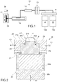
- a machine LIM is schematically shown.
- Said machine conventionally comprises a feeding and injection system 10 and a closure group 20.
- the feeding and injection system has the task of mixing the components of the plastic material, in particular silicone, and of feeding the plastic material in a fluid state to the closure group 20.
- the injection group is conventionally provided with a feeding pump 11 which takes the plastic material components from respective tanks 12a and 12b and feeds them to a dispensing group 13 and to a mixer 14.
- the produced mixture is injected into the closure group 20 by means of a generally cooled cylinder injection unit 15.
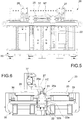
- the closure group 20 is represented at a conceptual level in figure 2 , while in figures 4 to 7 an example of embodiment of the closure group 20 is shown by way of non-limiting example.
- FIG. 2 shows a tank HT made of plastic material, in particular a header tank for a heat exchanger, more precisely for a car engine cooling radiator.
- the tank HT has a peripheral edge PE provided with a flange F projecting transversely towards the outside.
- this peripheral edge comprises two opposite long sides, visible in section in figure 2 , and two short opposite sides, not visible in the figures, which interconnect the long sides.
- the closure group 20 comprises a block or molding part 21 movable along a first axis, which in the example shown is a vertical axis indicated with z.
- the molding part 21 is mounted frontally on a punch 22 driven by an actuator or servomotor to implement such a linear motion, as indicated by the arrow Z1.
- a heating element 22a and a possible cooling element 22b are arranged on the punch 22.
- the molding part 21 has frontally a coupling surface 21a adapted to receive the peripheral edge PE of the tank HT.
- ducts (not shown) are formed in the body of the molding part 21, and possibly also in the body of the punch 22, which connect the cavity 23 to the feeding and injection system 10 in a per se known manner.
- the molding part 21 also has a centering protrusion 21b protruding from the coupling surface 21a and provided for being inserted into the cavity of the tank HT.
- the molding part 21 is removably mounted on the punch 22, so as to allow its replacement with other molding parts having cavities 23 with different geometries.
- the molding part 21 can be a piece in which only the functions of conveying the plastic material and defining the shape of the gasket are implemented, or, with reference to figure 3b , it can also be provided with the heating function, by arranging a heating element 21c on board the molding part 21.
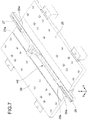
- the closure group 20 further comprises (at least) a pair of opposite carriages 25, 26 which slide along a second axis orthogonal to the first axis, which in the example shown is a horizontal axis, for example the axis y.
- the arrows Y1, Y2 in figure 2 show the movement of the carriage 25 and of the carriage 26, respectively.
- the carriages 25 and 26 are movable between an open position, in which they allow the insertion or withdrawal of the tank on/from the molding part 21, and a holding position, shown in figure 2 , in which the carriages 25, 26 cooperate to define a gap having a smaller cross-section than that of the flange F of the tank HT.
- two pairs of opposite carriages 25, 26 can be provided; 27, 28 respectively sliding along the second axis and along a third axis orthogonal to the first axis and to the second axis, which in the example illustrated can be the axis x.
- a pair of carriages, 25 and 26, is associated with the long sides of the tank HT, and the other pair of carriages, 27 and 28, is associated with the short sides of the tank HT.
- the molding part 21 is arranged in the center between the carriages 25, 26, 27 and 28.
- the forming part 21 is controllable to bring the flange F of the tank HT against an edge 25a, 26a of the carriages 25, 26 (or, respectively, against an edge 25a, 26a, 27a and 28a of the carriages 25, 26, 27 and 28) when these carriages are in the holding position.
- the molding part 21 can be controlled to apply against the carriages 25, 26 (or, respectively, against the carriages 25, 26, 27 and 28) a direct closing force along the first axis (vertical axis z in the example).
- the flange F of the tank HT is clamped between the edge of the carriages 25, 26 (or, respectively, against the carriages 25, 26, 27 and 28) and the coupling surface 21a of the molding part 21.
- the clamping force must be sized so as to withstand the pressure that is created in the cavity 23 when the plastic is injected.
- the rest of the tank HT protrudes freely through the gap defined by the carriages 25-28 and is not subjected to any load.
- the group 20 comprises a supporting structure 30 on which the components described above are arranged as well as the components intended for their movement and control.
- the movement system of the punch 22 comprises a servomotor 31 coupled to a transmission belt 32, through which the servomotor 31 controls a screw-nut mechanism 33 connected to the punch 22.
- the maintenance of the closing of the punch 21 is guaranteed by the servomotor 31 and possibly, if necessary, by mechanical stops (not shown) operated by pneumatic cylinders (not shown).
- the carriages 25, 26 associated with the long sides of the tank HT are coupled with sliding guides 35, 36 carried by the supporting structure 30.
- respective motors (not shown) are provided which also guarantee locking in the holding position.
- mechanical stops (not shown) can be provided which, if necessary, ensure further locking of the carriages 25, 26 in the holding position.
- the carriages 27, 28 associated with the short sides of the tank HT are coupled to a sliding guide 37 carried by the supporting structure 30.
- respective motors (not shown) are provided which also guarantee locking in the holding position.
- mechanical stops (not shown) can be provided which, if necessary, ensure further locking of the carriages 27, 28 in the holding position.
- the plastic tank HT to be insert-molded is positioned, manually or in an automated manner, on the molding part 21 ( figure 8a ). This step can take place only when the molding part 21 reaches the operating temperature at full speed following the heating received by the heating element (22a or 21c). The molding part 21 is in the starting position, translated downwards with respect to the working position.
- the molding part 21 and the tank HT positioned on it, translate in axis z closing the whole system as a package ( figure 8c ) and tightening the flange F of the tank HT between the coupling surface 21a of the molding part 21 and the edges 25a-28a of the carriages.
- the plastic material is then injected and subsequently cross-linked in the cavity 23 of the molding part 21 by means of the feeding and injection part 10.
Landscapes
- Engineering & Computer Science (AREA)
- Mechanical Engineering (AREA)
- Manufacturing & Machinery (AREA)
- Injection Moulding Of Plastics Or The Like (AREA)
- Diaphragms For Electromechanical Transducers (AREA)
- Closures For Containers (AREA)
- Moulds For Moulding Plastics Or The Like (AREA)
Applications Claiming Priority (1)
| Application Number | Priority Date | Filing Date | Title |
|---|---|---|---|
| IT102018000020761A IT201800020761A1 (it) | 2018-12-21 | 2018-12-21 | Macchina per il co-stampaggio di una guarnizione su una vasca di materia plastica. |
Publications (3)
| Publication Number | Publication Date |
|---|---|
| EP3670138A1 true EP3670138A1 (de) | 2020-06-24 |
| EP3670138B1 EP3670138B1 (de) | 2024-09-18 |
| EP3670138C0 EP3670138C0 (de) | 2024-09-18 |
Family
ID=66049508
Family Applications (1)
| Application Number | Title | Priority Date | Filing Date |
|---|---|---|---|
| EP19217677.4A Active EP3670138B1 (de) | 2018-12-21 | 2019-12-18 | Maschine zum umspritzen einer dichtung an einem tank aus kunststoffmaterial |
Country Status (3)
| Country | Link |
|---|---|
| EP (1) | EP3670138B1 (de) |
| ES (1) | ES2990167T3 (de) |
| IT (1) | IT201800020761A1 (de) |
Citations (2)
| Publication number | Priority date | Publication date | Assignee | Title |
|---|---|---|---|---|
| US5160474A (en) * | 1990-12-21 | 1992-11-03 | Cadillac Rubber & Plastics, Inc. | Overmolded gasket, heat exchanger tank incorporating the same and method for making the same |
| US20180221900A1 (en) * | 2015-08-05 | 2018-08-09 | Illinois Tool Works Inc. | Injection molding tool and method |
Family Cites Families (3)
| Publication number | Priority date | Publication date | Assignee | Title |
|---|---|---|---|---|
| US6238610B1 (en) * | 1995-05-02 | 2001-05-29 | Calsonic Kansei Corporation | Heat exchanger tank and method of producing the same |
| JP5585456B2 (ja) * | 2011-01-06 | 2014-09-10 | 株式会社デンソー | 熱交換器およびその製造方法 |
| DE102013226434A1 (de) * | 2013-12-18 | 2015-06-18 | MAHLE Behr GmbH & Co. KG | Wärmeübertrager |
-
2018
- 2018-12-21 IT IT102018000020761A patent/IT201800020761A1/it unknown
-
2019
- 2019-12-18 EP EP19217677.4A patent/EP3670138B1/de active Active
- 2019-12-18 ES ES19217677T patent/ES2990167T3/es active Active
Patent Citations (2)
| Publication number | Priority date | Publication date | Assignee | Title |
|---|---|---|---|---|
| US5160474A (en) * | 1990-12-21 | 1992-11-03 | Cadillac Rubber & Plastics, Inc. | Overmolded gasket, heat exchanger tank incorporating the same and method for making the same |
| US20180221900A1 (en) * | 2015-08-05 | 2018-08-09 | Illinois Tool Works Inc. | Injection molding tool and method |
Also Published As
| Publication number | Publication date |
|---|---|
| IT201800020761A1 (it) | 2020-06-21 |
| ES2990167T3 (es) | 2024-11-29 |
| EP3670138B1 (de) | 2024-09-18 |
| EP3670138C0 (de) | 2024-09-18 |
Similar Documents
| Publication | Publication Date | Title |
|---|---|---|
| EP2939820B1 (de) | Verfahren und Vorrichtung zur Herstellung eines Verbundteils eines Flugzeugs | |
| US8894903B2 (en) | Method for the manufacture of a fiber-reinforced component | |
| EP2650097A1 (de) | Vorrichtung und Verfahren zum Pressformen von Kunststoffgegenständen mit Fasern | |
| US11766816B2 (en) | Molded article manufacturing method, molded article, and molded article manufacturing apparatus | |
| US20160346967A1 (en) | Method for manufacturing liquid supply member | |
| JP2012192543A (ja) | 樹脂製品の成形方法とそれに用いる成形装置 | |
| US6638047B2 (en) | Molding machine | |
| US10751921B2 (en) | Receiving device and injection-molding method | |
| CN107000288B (zh) | 用于具有电子元件的载体的受控重叠注塑的模具,模制设备和方法以及模制产品 | |
| RU2260511C2 (ru) | Способ и устройство для горячей формовки изделий из термопластичного материала | |
| EP3670138B1 (de) | Maschine zum umspritzen einer dichtung an einem tank aus kunststoffmaterial | |
| KR20120095515A (ko) | 열간 및 냉각 시스템 일체형 핫 프레스 성형기 | |
| CN110667120A (zh) | 制造多个相互焊接的塑料模制件形成的构件的设备和方法 | |
| EP2019744B1 (de) | System zum integrieren eines einsatzes mit einem formkörper | |
| CN214447976U (zh) | 一种直排式橡胶制品注射成型机 | |
| EP2635428B1 (de) | Thermisches konsolidierungssystem und verfahren | |
| CN210820607U (zh) | 一种高效快速成型的注塑模具 | |
| MXPA06008099A (es) | Moldeo por compresion de inyeccion. | |
| CN101391485A (zh) | 模制件的热成型 | |
| CN209240363U (zh) | 一种双色转塔机 | |
| KR102346454B1 (ko) | 인서트 부품이 자동 공급되는 사출 성형 장치 | |
| CN210255051U (zh) | 一种机器人控制的光孔球阀装配机 | |
| EP3481618A1 (de) | Thermoformmaschine und -verfahren | |
| DE102008015534A1 (de) | Vorrichtung und Verfahren zum Herstellen von Kunststoffformteilen | |
| US9868251B2 (en) | Method for producing plastic containers |
Legal Events
| Date | Code | Title | Description |
|---|---|---|---|
| PUAI | Public reference made under article 153(3) epc to a published international application that has entered the european phase |
Free format text: ORIGINAL CODE: 0009012 |
|
| STAA | Information on the status of an ep patent application or granted ep patent |
Free format text: STATUS: THE APPLICATION HAS BEEN PUBLISHED |
|
| AK | Designated contracting states |
Kind code of ref document: A1 Designated state(s): AL AT BE BG CH CY CZ DE DK EE ES FI FR GB GR HR HU IE IS IT LI LT LU LV MC MK MT NL NO PL PT RO RS SE SI SK SM TR |
|
| AX | Request for extension of the european patent |
Extension state: BA ME |
|
| STAA | Information on the status of an ep patent application or granted ep patent |
Free format text: STATUS: REQUEST FOR EXAMINATION WAS MADE |
|
| 17P | Request for examination filed |
Effective date: 20201215 |
|
| RBV | Designated contracting states (corrected) |
Designated state(s): AL AT BE BG CH CY CZ DE DK EE ES FI FR GB GR HR HU IE IS IT LI LT LU LV MC MK MT NL NO PL PT RO RS SE SI SK SM TR |
|
| STAA | Information on the status of an ep patent application or granted ep patent |
Free format text: STATUS: EXAMINATION IS IN PROGRESS |
|
| 17Q | First examination report despatched |
Effective date: 20220201 |
|
| GRAP | Despatch of communication of intention to grant a patent |
Free format text: ORIGINAL CODE: EPIDOSNIGR1 |
|
| STAA | Information on the status of an ep patent application or granted ep patent |
Free format text: STATUS: GRANT OF PATENT IS INTENDED |
|
| RIC1 | Information provided on ipc code assigned before grant |
Ipc: B29L 31/30 20060101ALN20240402BHEP Ipc: B29C 45/14 20060101ALI20240402BHEP Ipc: B29C 67/24 20060101ALI20240402BHEP Ipc: B29C 45/33 20060101AFI20240402BHEP |
|
| INTG | Intention to grant announced |
Effective date: 20240419 |
|
| GRAS | Grant fee paid |
Free format text: ORIGINAL CODE: EPIDOSNIGR3 |
|
| GRAA | (expected) grant |
Free format text: ORIGINAL CODE: 0009210 |
|
| STAA | Information on the status of an ep patent application or granted ep patent |
Free format text: STATUS: THE PATENT HAS BEEN GRANTED |
|
| AK | Designated contracting states |
Kind code of ref document: B1 Designated state(s): AL AT BE BG CH CY CZ DE DK EE ES FI FR GB GR HR HU IE IS IT LI LT LU LV MC MK MT NL NO PL PT RO RS SE SI SK SM TR |
|
| REG | Reference to a national code |
Ref country code: GB Ref legal event code: FG4D |
|
| REG | Reference to a national code |
Ref country code: CH Ref legal event code: EP |
|
| REG | Reference to a national code |
Ref country code: DE Ref legal event code: R096 Ref document number: 602019059023 Country of ref document: DE |
|
| REG | Reference to a national code |
Ref country code: IE Ref legal event code: FG4D |
|
| U01 | Request for unitary effect filed |
Effective date: 20240918 |
|
| U07 | Unitary effect registered |
Designated state(s): AT BE BG DE DK EE FI FR IT LT LU LV MT NL PT RO SE SI Effective date: 20241010 |
|
| REG | Reference to a national code |
Ref country code: ES Ref legal event code: FG2A Ref document number: 2990167 Country of ref document: ES Kind code of ref document: T3 Effective date: 20241129 |
|
| U20 | Renewal fee for the european patent with unitary effect paid |
Year of fee payment: 6 Effective date: 20241121 |
|
| PG25 | Lapsed in a contracting state [announced via postgrant information from national office to epo] |
Ref country code: NO Free format text: LAPSE BECAUSE OF FAILURE TO SUBMIT A TRANSLATION OF THE DESCRIPTION OR TO PAY THE FEE WITHIN THE PRESCRIBED TIME-LIMIT Effective date: 20241218 |
|
| PG25 | Lapsed in a contracting state [announced via postgrant information from national office to epo] |
Ref country code: GR Free format text: LAPSE BECAUSE OF FAILURE TO SUBMIT A TRANSLATION OF THE DESCRIPTION OR TO PAY THE FEE WITHIN THE PRESCRIBED TIME-LIMIT Effective date: 20241219 |
|
| PG25 | Lapsed in a contracting state [announced via postgrant information from national office to epo] |
Ref country code: HR Free format text: LAPSE BECAUSE OF FAILURE TO SUBMIT A TRANSLATION OF THE DESCRIPTION OR TO PAY THE FEE WITHIN THE PRESCRIBED TIME-LIMIT Effective date: 20240918 |
|
| PG25 | Lapsed in a contracting state [announced via postgrant information from national office to epo] |
Ref country code: RS Free format text: LAPSE BECAUSE OF FAILURE TO SUBMIT A TRANSLATION OF THE DESCRIPTION OR TO PAY THE FEE WITHIN THE PRESCRIBED TIME-LIMIT Effective date: 20241218 |
|
| PG25 | Lapsed in a contracting state [announced via postgrant information from national office to epo] |
Ref country code: RS Free format text: LAPSE BECAUSE OF FAILURE TO SUBMIT A TRANSLATION OF THE DESCRIPTION OR TO PAY THE FEE WITHIN THE PRESCRIBED TIME-LIMIT Effective date: 20241218 Ref country code: NO Free format text: LAPSE BECAUSE OF FAILURE TO SUBMIT A TRANSLATION OF THE DESCRIPTION OR TO PAY THE FEE WITHIN THE PRESCRIBED TIME-LIMIT Effective date: 20241218 Ref country code: HR Free format text: LAPSE BECAUSE OF FAILURE TO SUBMIT A TRANSLATION OF THE DESCRIPTION OR TO PAY THE FEE WITHIN THE PRESCRIBED TIME-LIMIT Effective date: 20240918 Ref country code: GR Free format text: LAPSE BECAUSE OF FAILURE TO SUBMIT A TRANSLATION OF THE DESCRIPTION OR TO PAY THE FEE WITHIN THE PRESCRIBED TIME-LIMIT Effective date: 20241219 |
|
| PGFP | Annual fee paid to national office [announced via postgrant information from national office to epo] |
Ref country code: TR Payment date: 20241209 Year of fee payment: 6 |
|
| PG25 | Lapsed in a contracting state [announced via postgrant information from national office to epo] |
Ref country code: IS Free format text: LAPSE BECAUSE OF FAILURE TO SUBMIT A TRANSLATION OF THE DESCRIPTION OR TO PAY THE FEE WITHIN THE PRESCRIBED TIME-LIMIT Effective date: 20250118 |
|
| PG25 | Lapsed in a contracting state [announced via postgrant information from national office to epo] |
Ref country code: SM Free format text: LAPSE BECAUSE OF FAILURE TO SUBMIT A TRANSLATION OF THE DESCRIPTION OR TO PAY THE FEE WITHIN THE PRESCRIBED TIME-LIMIT Effective date: 20240918 |
|
| PGFP | Annual fee paid to national office [announced via postgrant information from national office to epo] |
Ref country code: ES Payment date: 20250102 Year of fee payment: 6 |
|
| PG25 | Lapsed in a contracting state [announced via postgrant information from national office to epo] |
Ref country code: CZ Free format text: LAPSE BECAUSE OF FAILURE TO SUBMIT A TRANSLATION OF THE DESCRIPTION OR TO PAY THE FEE WITHIN THE PRESCRIBED TIME-LIMIT Effective date: 20240918 Ref country code: PL Free format text: LAPSE BECAUSE OF FAILURE TO SUBMIT A TRANSLATION OF THE DESCRIPTION OR TO PAY THE FEE WITHIN THE PRESCRIBED TIME-LIMIT Effective date: 20240918 |
|
| PG25 | Lapsed in a contracting state [announced via postgrant information from national office to epo] |
Ref country code: SK Free format text: LAPSE BECAUSE OF FAILURE TO SUBMIT A TRANSLATION OF THE DESCRIPTION OR TO PAY THE FEE WITHIN THE PRESCRIBED TIME-LIMIT Effective date: 20240918 |
|
| PG25 | Lapsed in a contracting state [announced via postgrant information from national office to epo] |
Ref country code: MC Free format text: LAPSE BECAUSE OF FAILURE TO SUBMIT A TRANSLATION OF THE DESCRIPTION OR TO PAY THE FEE WITHIN THE PRESCRIBED TIME-LIMIT Effective date: 20240918 |
|
| PLBE | No opposition filed within time limit |
Free format text: ORIGINAL CODE: 0009261 |
|
| STAA | Information on the status of an ep patent application or granted ep patent |
Free format text: STATUS: NO OPPOSITION FILED WITHIN TIME LIMIT |
|
| REG | Reference to a national code |
Ref country code: CH Ref legal event code: PL |
|
| 26N | No opposition filed |
Effective date: 20250619 |
|
| GBPC | Gb: european patent ceased through non-payment of renewal fee |
Effective date: 20241218 |