EP3669958A1 - Informationsverarbeitungsvorrichtung, informationsverarbeitungsverfahren und programm - Google Patents
Informationsverarbeitungsvorrichtung, informationsverarbeitungsverfahren und programm Download PDFInfo
- Publication number
- EP3669958A1 EP3669958A1 EP18847028.0A EP18847028A EP3669958A1 EP 3669958 A1 EP3669958 A1 EP 3669958A1 EP 18847028 A EP18847028 A EP 18847028A EP 3669958 A1 EP3669958 A1 EP 3669958A1
- Authority
- EP
- European Patent Office
- Prior art keywords
- motion
- data
- section
- processing
- detection
- Prior art date
- Legal status (The legal status is an assumption and is not a legal conclusion. Google has not performed a legal analysis and makes no representation as to the accuracy of the status listed.)
- Withdrawn
Links
- VWJXVEHXMYFXCC-UHFFFAOYSA-N CC(C=[N+]=[I-])[N+](C)(C)[O-] Chemical compound CC(C=[N+]=[I-])[N+](C)(C)[O-] VWJXVEHXMYFXCC-UHFFFAOYSA-N 0.000 description 1
Images




















Classifications
-
- G—PHYSICS
- G16—INFORMATION AND COMMUNICATION TECHNOLOGY [ICT] SPECIALLY ADAPTED FOR SPECIFIC APPLICATION FIELDS
- G16H—HEALTHCARE INFORMATICS, i.e. INFORMATION AND COMMUNICATION TECHNOLOGY [ICT] SPECIALLY ADAPTED FOR THE HANDLING OR PROCESSING OF MEDICAL OR HEALTHCARE DATA
- G16H40/00—ICT specially adapted for the management or administration of healthcare resources or facilities; ICT specially adapted for the management or operation of medical equipment or devices
- G16H40/60—ICT specially adapted for the management or administration of healthcare resources or facilities; ICT specially adapted for the management or operation of medical equipment or devices for the operation of medical equipment or devices
- G16H40/63—ICT specially adapted for the management or administration of healthcare resources or facilities; ICT specially adapted for the management or operation of medical equipment or devices for the operation of medical equipment or devices for local operation
-
- A—HUMAN NECESSITIES
- A61—MEDICAL OR VETERINARY SCIENCE; HYGIENE
- A61B—DIAGNOSIS; SURGERY; IDENTIFICATION
- A61B5/00—Measuring for diagnostic purposes; Identification of persons
- A61B5/103—Measuring devices for testing the shape, pattern, colour, size or movement of the body or parts thereof, for diagnostic purposes
- A61B5/11—Measuring movement of the entire body or parts thereof, e.g. head or hand tremor or mobility of a limb
- A61B5/1123—Discriminating type of movement, e.g. walking or running
-
- A—HUMAN NECESSITIES
- A61—MEDICAL OR VETERINARY SCIENCE; HYGIENE
- A61B—DIAGNOSIS; SURGERY; IDENTIFICATION
- A61B5/00—Measuring for diagnostic purposes; Identification of persons
- A61B5/0002—Remote monitoring of patients using telemetry, e.g. transmission of vital signals via a communication network
- A61B5/0015—Remote monitoring of patients using telemetry, e.g. transmission of vital signals via a communication network characterised by features of the telemetry system
- A61B5/0024—Remote monitoring of patients using telemetry, e.g. transmission of vital signals via a communication network characterised by features of the telemetry system for multiple sensor units attached to the patient, e.g. using a body or personal area network
-
- A—HUMAN NECESSITIES
- A61—MEDICAL OR VETERINARY SCIENCE; HYGIENE
- A61B—DIAGNOSIS; SURGERY; IDENTIFICATION
- A61B5/00—Measuring for diagnostic purposes; Identification of persons
- A61B5/103—Measuring devices for testing the shape, pattern, colour, size or movement of the body or parts thereof, for diagnostic purposes
- A61B5/11—Measuring movement of the entire body or parts thereof, e.g. head or hand tremor or mobility of a limb
- A61B5/1113—Local tracking of patients, e.g. in a hospital or private home
- A61B5/1114—Tracking parts of the body
-
- A—HUMAN NECESSITIES
- A61—MEDICAL OR VETERINARY SCIENCE; HYGIENE
- A61B—DIAGNOSIS; SURGERY; IDENTIFICATION
- A61B5/00—Measuring for diagnostic purposes; Identification of persons
- A61B5/103—Measuring devices for testing the shape, pattern, colour, size or movement of the body or parts thereof, for diagnostic purposes
- A61B5/11—Measuring movement of the entire body or parts thereof, e.g. head or hand tremor or mobility of a limb
- A61B5/1126—Measuring movement of the entire body or parts thereof, e.g. head or hand tremor or mobility of a limb using a particular sensing technique
- A61B5/1128—Measuring movement of the entire body or parts thereof, e.g. head or hand tremor or mobility of a limb using a particular sensing technique using image analysis
-
- A—HUMAN NECESSITIES
- A61—MEDICAL OR VETERINARY SCIENCE; HYGIENE
- A61B—DIAGNOSIS; SURGERY; IDENTIFICATION
- A61B5/00—Measuring for diagnostic purposes; Identification of persons
- A61B5/72—Signal processing specially adapted for physiological signals or for diagnostic purposes
- A61B5/7235—Details of waveform analysis
- A61B5/7264—Classification of physiological signals or data, e.g. using neural networks, statistical classifiers, expert systems or fuzzy systems
- A61B5/7267—Classification of physiological signals or data, e.g. using neural networks, statistical classifiers, expert systems or fuzzy systems involving training the classification device
-
- A—HUMAN NECESSITIES
- A63—SPORTS; GAMES; AMUSEMENTS
- A63B—APPARATUS FOR PHYSICAL TRAINING, GYMNASTICS, SWIMMING, CLIMBING, OR FENCING; BALL GAMES; TRAINING EQUIPMENT
- A63B24/00—Electric or electronic controls for exercising apparatus of preceding groups; Controlling or monitoring of exercises, sportive games, training or athletic performances
- A63B24/0062—Monitoring athletic performances, e.g. for determining the work of a user on an exercise apparatus, the completed jogging or cycling distance
-
- A—HUMAN NECESSITIES
- A63—SPORTS; GAMES; AMUSEMENTS
- A63B—APPARATUS FOR PHYSICAL TRAINING, GYMNASTICS, SWIMMING, CLIMBING, OR FENCING; BALL GAMES; TRAINING EQUIPMENT
- A63B69/00—Training appliances or apparatus for special sports
-
- A—HUMAN NECESSITIES
- A63—SPORTS; GAMES; AMUSEMENTS
- A63B—APPARATUS FOR PHYSICAL TRAINING, GYMNASTICS, SWIMMING, CLIMBING, OR FENCING; BALL GAMES; TRAINING EQUIPMENT
- A63B71/00—Games or sports accessories not covered in groups A63B1/00 - A63B69/00
- A63B71/06—Indicating or scoring devices for games or players, or for other sports activities
-
- A—HUMAN NECESSITIES
- A63—SPORTS; GAMES; AMUSEMENTS
- A63J—DEVICES FOR THEATRES, CIRCUSES, OR THE LIKE; CONJURING APPLIANCES OR THE LIKE
- A63J5/00—Auxiliaries for producing special effects on stages, or in circuses or arenas
- A63J5/02—Arrangements for making stage effects; Auxiliary stage appliances
-
- G—PHYSICS
- G16—INFORMATION AND COMMUNICATION TECHNOLOGY [ICT] SPECIALLY ADAPTED FOR SPECIFIC APPLICATION FIELDS
- G16H—HEALTHCARE INFORMATICS, i.e. INFORMATION AND COMMUNICATION TECHNOLOGY [ICT] SPECIALLY ADAPTED FOR THE HANDLING OR PROCESSING OF MEDICAL OR HEALTHCARE DATA
- G16H20/00—ICT specially adapted for therapies or health-improving plans, e.g. for handling prescriptions, for steering therapy or for monitoring patient compliance
- G16H20/30—ICT specially adapted for therapies or health-improving plans, e.g. for handling prescriptions, for steering therapy or for monitoring patient compliance relating to physical therapies or activities, e.g. physiotherapy, acupressure or exercising
-
- G—PHYSICS
- G16—INFORMATION AND COMMUNICATION TECHNOLOGY [ICT] SPECIALLY ADAPTED FOR SPECIFIC APPLICATION FIELDS
- G16H—HEALTHCARE INFORMATICS, i.e. INFORMATION AND COMMUNICATION TECHNOLOGY [ICT] SPECIALLY ADAPTED FOR THE HANDLING OR PROCESSING OF MEDICAL OR HEALTHCARE DATA
- G16H50/00—ICT specially adapted for medical diagnosis, medical simulation or medical data mining; ICT specially adapted for detecting, monitoring or modelling epidemics or pandemics
- G16H50/30—ICT specially adapted for medical diagnosis, medical simulation or medical data mining; ICT specially adapted for detecting, monitoring or modelling epidemics or pandemics for calculating health indices; for individual health risk assessment
-
- A—HUMAN NECESSITIES
- A63—SPORTS; GAMES; AMUSEMENTS
- A63B—APPARATUS FOR PHYSICAL TRAINING, GYMNASTICS, SWIMMING, CLIMBING, OR FENCING; BALL GAMES; TRAINING EQUIPMENT
- A63B24/00—Electric or electronic controls for exercising apparatus of preceding groups; Controlling or monitoring of exercises, sportive games, training or athletic performances
- A63B24/0003—Analysing the course of a movement or motion sequences during an exercise or trainings sequence, e.g. swing for golf or tennis
- A63B24/0006—Computerised comparison for qualitative assessment of motion sequences or the course of a movement
- A63B2024/0012—Comparing movements or motion sequences with a registered reference
- A63B2024/0015—Comparing movements or motion sequences with computerised simulations of movements or motion sequences, e.g. for generating an ideal template as reference to be achieved by the user
-
- G—PHYSICS
- G06—COMPUTING OR CALCULATING; COUNTING
- G06V—IMAGE OR VIDEO RECOGNITION OR UNDERSTANDING
- G06V40/00—Recognition of biometric, human-related or animal-related patterns in image or video data
- G06V40/20—Movements or behaviour, e.g. gesture recognition
- G06V40/23—Recognition of whole body movements, e.g. for sport training
Definitions
- the present disclosure relates to an information processor, an information processing method, and a program, and more particularly, to an information processor, an information processing method, and a program suitable for use in a case of recognizing a motion of an object.
- a motion-related arithmetic unit estimates an exercise rhythm of each user, calculates a degree of difference between the exercise rhythm of each user and a basic exercise rhythm, or a degree of difference between the exercise rhythms of the users, and feeds back results thereof to the user (see, e.g., PTL 1).
- the present technology has been made in view of such a circumstance, and makes it possible to easily and accurately recognize a motion of an object such as a person.
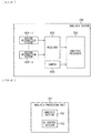
- An information processor includes a required time estimation section that estimates first required time required for communication data to arrive at an apparatus in a subsequent stage, and a transmission section that transmits the communication data and required time information including the first required time to the apparatus in the subsequent stage.
- the information processor recognizes a motion of an object on the basis of a plurality of detection data indicating respective movements of a plurality of detection positions of the object detected by a plurality of sensor apparatuses at the plurality of detection positions, and controls an output of control data used for controlling of processing corresponding to the motion of the object.
- a program causes a computer to execute processing including a motion recognition step that recognizes a motion of an object on the basis of a plurality of detection data indicating respective movements of a plurality of detection positions of the object detected by a plurality of sensor apparatuses at the plurality of detection positions, and an output control step that controls an output of control data used for controlling of processing corresponding to the motion of the object.
- a motion of an object is recognized on the basis of a plurality of detection data indicating respective movements of a plurality of detection positions of the object detected by a plurality of sensor apparatuses at the plurality of detection positions, and an output of control data used for controlling of processing corresponding to the motion of the object is controlled.
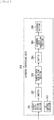
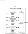
- FIG. 1 illustrates a configuration example of a motion recognition system 100 which is a first embodiment of a motion recognition system to which the present technology is applied.
- the motion recognition system 100 is a system that performs recognition processing of motion of a user.
- the motion refers to, for example, a unit of movements constituting an action of a user (person) on the basis of predetermined classification.
- the motion is a user movement in a time period shorter than action.
- the motion may be a movement of the whole body of the user or a movement of a portion of the body of the user.
- an action is an aggregation of a series of motions on the basis of predetermined classification, and includes a combination of a plurality of motions.
- an aggregation of a series of motions for achieving a predetermined purpose is an action.
- the actions to be subjected to motion recognition are classified on the basis of sports events such as dance, ice skating, rugby, triathlon, swimming, and mountain climbing.
- sports events such as dance, ice skating, rugby, triathlon, swimming, and mountain climbing.
- sports in which a plurality of events are combined such as all-around gymnastics, may be regarded as one action.
- an action to be a target of motion recognition is classified on the basis of actions of daily life such as commuting, driving, work, study, raising children, sleeping, cooking, eating, watching TV, singing, playing, photographing, and the like.
- a motion to be recognized is classified on the basis of dance techniques such as slide, jerk, or biz markie, with respect to the action of dancing.
- the motion to be recognized is classified on the basis of dance movements such as rotation, jump, step, rolling, and pitching, with respect to the action of dancing. It is to be noted that motions to be recognized may be classified on the basis of both techniques and movements of dancing.
- a motion to be recognized is classified on the basis of techniques of figure skating such as axel, lutz, or salchow, with respect to an action of figure skating.
- the motion to be recognized is classified on the basis of the movements of the figure skating, such as sliding, rotating, jumping, and stepping, with respect to the action of the figure skating. It is to be noted that motion to be recognized may be classified on the basis of both techniques and movements of the figure skating.
- a motion to be recognized is classified on the basis of rugby-specific movements such as scrum, try, run, pass, and tackle, with respect to the action of rugby.
- the motion to be recognized is classified on the basis of general motions such as running, jumping, throwing, catching, and hitting, with respect to the action of rugby, for example. It is to be noted that motion to be recognized may be classified on the basis of both rugby-specific movements and the general movements.
- a motion to be recognized is classified on the basis of swimming strokes such as crawl, breaststroke, butterfly, and back stroke, with respect to the action of swimming.
- the motion to be recognized is classified on the basis of the movements of swimming such as jumping-in, turn, breathing, and kick, with respect to the action of swimming. It is to be noted that motions to be recognized may be classified on the basis of both the stroke and the movement of swimming.
- a motion to be recognized is classified on the basis of triathlon events of swimming, cycling, and running, with respect to the action of the triathlon.
- a motion to be recognized is classified on the basis of events of gymnastics such as vault, floor, and still rings, with respect to the action of the all-around gymnastics.
- a motion to be recognized is classified on the basis of movements at the time of commuting such as walking, resting, riding on a train, or climbing a staircase, with respect to the action of commuting.
- a motion to be recognized is classified on the basis of movements at the time of driving such as accelerating, braking, gear-changing, and rear confirmation, with respect to the action of driving.
- a motion to be recognized is classified on the basis of movements at the time of working, such as speaking, listening, writing, using a telephone or a PC, and discussion, with respect to the action of working.
- each of the events (swimming, cycling, and running) of the triathlon may be an action to be subjected to motion recognition independently. That is, the swimming, cycling, or running may be classified into actions, and motion recognition processing may be performed for each of the actions.
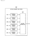
- the motion recognition system 100 includes a wearable sensor 101-1 to a wearable sensor 101-6, and a motion recognizer 102.
- wearable sensor 101-1 to the wearable sensor 101-6 need not be individually distinguished, they are simply referred to as a wearable sensor 101.
- Each wearable sensor 101 is a sensor apparatus that is attached to a different position of a user who is a target of motion recognition (hereinafter, referred to as a detection point or a detection position) and detects a movement of each detection point.
- Each wearable sensor 101 transmits to the motion recognizer 102 a communication packet including motion detection data indicating motion detection results of the respective detection points.
- the motion recognizer 102 is installed at a position remote from the user, for example. Then, the motion recognizer 102 performs processing of motion recognition of the user on the basis of the movements of the detected points of the user detected by the respective wearable sensors 101. The motion recognizer 102 transmits control data used for controlling of processing corresponding to the motion of the user (hereinafter, referred to as motion control data) to an apparatus in a subsequent stage.
- motion control data used for controlling of processing corresponding to the motion of the user
- the wearable sensor 101 for communication between the wearable sensor 101 and the motion recognizer 102, for example, low-delay near field communication of any system is adopted. By adopting the near field communication, it is possible to reduce power consumption of the wearable sensor 101 and to miniaturize the wearable sensor 101.
- the communication between the motion recognizer 102 and the apparatus in a subsequent stage adopts, for example, wireless communication or wired communication of any system.
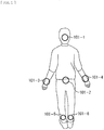
- FIG. 2 schematically illustrates examples of attaching positions (detection points) of the wearable sensors 101. It is to be noted that, in the diagram, the attaching positions of the wearable sensor 101 are indicated by circles.
- the wearable sensor 101-1 is attached to the head of the user and detects the movement of the head.
- the wearable sensor 101-2 is attached to the hip of the user and detects the movement of the hip. That is, the wearable sensor 101-1 and the wearable sensor 101-2 detect the movement of body trunk, gravity center, posture, and the like of the user.
- the wearable sensor 101-3 is attached to the user's left wrist and detects movement of the left wrist.
- the wearable sensor 101-4 is attached to the user's right wrist and detects movement of the right wrist. That is, the wearable sensor 101-3 and the wearable sensor 101-4 detect movements of both hands, snaps of wrists, and the like of the user.
- the wearable sensor 101-5 is attached to the user's left ankle and detects movement of the left ankle.
- the wearable sensor 101-6 is attached to the user's right ankle and detects movement of the right ankle. That is, the wearable sensor 101-5 and the wearable sensor 101-6 detect movements, steps, and the like of both feet of the user.
- the motion of the user is recognized on the basis of an interlocking property of the mutual movements of the body trunk, both hands, and both feet of the user.
- the number of the wearable sensors 101 attached and the attaching positions thereof in FIGs. 1 and 2 are exemplary, and are appropriately changed depending on the type, etc. of motions to be recognized.
- the wearable sensor 101 may be attached to two or more of head, torso, left hand, right hand, left foot, and right foot of the user.
- the wearable sensor 101 there is no particular limitation on how to attach the wearable sensor 101.
- a band, a belt, a supporter, a tape, a clip, or the like may be used. It is to be noted that, in order to detect the movement of each of the detection points with high accuracy, it is desirable that the attaching position of each wearable sensor 101 do not move as much as possible to such a degree as not to hinder the movement of the user or to cause a sense of discomfort to the user.
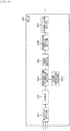
- FIG. 3 illustrates a configuration example of the wearable sensor 101 in FIG. 1 .
- FIG. 4 illustrates examples of specifications of sensors of the wearable sensor 101.
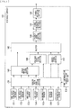
- the wearable sensor 101 includes an HDR (High Dynamic Range) acceleration sensor 131, an LDR (Low Dynamic Range) acceleration sensor 132, an HDR (High Dynamic Range) gyro sensor 133, an LDR (Low Dynamic Range) gyro sensor 134, a geomagnetic sensor 135, a strain sensor 136, a barometric sensor 137, a time information acquisition section 138, a sensor data acquisition section 139, a merge processing section 140, a posture detection section 141, a correction section 142, a buffer 143, a packet generation section 144, a transmission control section 145, and a transmission section 146.
- HDR High Dynamic Range
- LDR Low Dynamic Range
- gyro sensor 133 Low Dynamic Range
- LDR (Low Dynamic Range) gyro sensor 134 a geomagnetic sensor 135, a strain sensor 136, a barometric sensor 137, a time information acquisition section 138, a sensor data
- the HDR acceleration sensor 131 detects accelerations in three axial directions of a pitch axis (x-axis), a roll axis (y-axis), and a yaw axis (z-axis) at a position (detection point) where the wearable sensor 101 is attached. For example, the HDR acceleration sensor 131 samples accelerations of detection points at a sampling frequency of 1024 Hz, and outputs sensor data of 16 bits ⁇ 3 axes (hereinafter, referred to as HDR acceleration data).
- the LDR acceleration sensor 132 detects acceleration of the detection points in the three axial directions of the pitch axis, the roll axis, and the yaw axis. For example, the LDR acceleration sensor 132 samples accelerations of the detection points at a sampling frequency of 1024 Hz, and outputs sensor data of 16 bits ⁇ 3 axes (hereinafter, referred to as LDR acceleration data).
- the HDR acceleration sensor 131 has a wider dynamic range of detectable acceleration than that of the LDR acceleration sensor 132.
- the HDR acceleration sensor 131 outputs sensor data at ⁇ 32G, while the LDR acceleration sensor 132 outputs sensor data at ⁇ 16G.
- the HDR gyro sensor 133 detects an angular velocity of a detection point around three axes, i.e., around the pitch axis, around the roll axis, and around the yaw axis. For example, the HDR gyro sensor 133 samples angular velocities of the detection points at a sampling frequency of 1024 Hz, and outputs sensor data of 16 bits ⁇ 3 axes (hereinafter, referred to as HDR angular velocity data).
- the LDR gyro sensor 134 detects an angular velocity of a detection point around three axes, i.e., around the pitch axis, around the roll axis, and around the yaw axis. For example, the LDR gyro sensor 134 samples angular velocities of the detection points at a sampling frequency of 1024 Hz, and outputs sensor data of 16 bits ⁇ 3 axes (hereinafter, referred to as LDR angular velocity data).
- the HDR gyro sensor 133 has a wider dynamic range of detectable angular velocity than that of the LDR gyro sensor 134.
- the HDR gyro sensor 133 outputs sensor data at ⁇ 4000 dps, while the LDR gyro sensor 134 outputs sensor data at ⁇ 2000 dps.
- the geomagnetic sensor 135 detects geomagnetism in the three axial directions of the pitch axis, the roll axis, and the yaw axis near the detection points. For example, the geomagnetic sensor 135 samples the geomagnetism near the detection points at a sampling frequency of 128 Hz, and outputs sensor data of 16 bits ⁇ 3 axes (hereinafter, referred to as geomagnetism data).
- the strain sensor 136 detects strain of the detection point in two axial directions of the pitch axis and the roll axis (e.g., expansion and contraction of the detection point). For example, the strain sensor 136 samples strains of the detection points at a sampling frequency of 256 Hz, and outputs sensor data of 16-bit ⁇ 2-axis (hereinafter, referred to as strain data).
- the barometric sensor 137 detects a barometric pressure near the detection point. For example, the position of the detection point in the height direction is detected on the basis of the barometric pressure near the detection point. For example, the barometric sensor 137 samples barometric pressures near the detection point at a sampling frequency of 128 Hz, and outputs 24-bit sensor data (hereinafter, referred to as barometric pressure data).
- the time information acquisition section 138 is configured by, for example, a clock, etc., acquires time information indicating the current time, and supplies the acquired time information to the sensor data acquisition section 139.
- the sensor data acquisition section 139 acquires HDR acceleration data, LDR acceleration data, HDR angular velocity data, and LDR angular velocity data from the HDR acceleration sensor 131, the LDR acceleration sensor 132, the HDR gyro sensor 133, and the LDR gyro sensor 134, respectively; adds the acquired time to the acquired data; and supplies the resulting acquired data to the merge processing section 140. Further, the sensor data acquisition section 139 acquires geomagnetic data from the geomagnetic sensor 135, adds the acquired time to the acquired data, and supplies the resulting acquired data to the posture detection section 141. Further, the sensor data acquisition section 139 acquires strain data and barometric pressure data from the strain sensor 136 and the barometric sensor 137, respectively, adds the acquired time to the acquired data, and supplies the resulting acquired data to the correction section 142.
- the merge processing section 140 performs merge processing of HDR acceleration data and LDR acceleration data, and merge processing of HDR angular velocity data and LDR angular velocity data.
- the merge processing section 140 supplies the merged acceleration data and angular velocity data to the posture detection section 141 and the buffer 143.
- the posture detection section 141 detects postures of the detection points on the basis of acceleration data, angular velocity data, and geomagnetic data.
- the posture of the detection point is represented by, for example, Euler angles.
- the posture detection section 141 supplies data indicating calculated results (hereinafter, referred to as posture data) to the buffer 143.
- the correction section 142 corrects the strain data and the barometric pressure data, and supplies the corrected strain data and barometric pressure data to the buffer 143.
- the buffer 143 temporarily accumulates posture data, acceleration data, angular velocity data, strain data, and barometric pressure data.
- the packet generation section 144 generates a communication packet for transmission of data (hereinafter, referred to as motion detection data) including posture data, acceleration data, angular velocity data, strain data, and barometric pressure data accumulated in the buffer 143, and supplies the communication packet to the transmission control section 145.
- data hereinafter, referred to as motion detection data
- the transmission control section 145 controls transmission of the communication packet by the transmission section 146.
- the transmission section 146 transmits the communication packet to the motion recognizer 102 by wireless communication of a predetermined system.
- each section of the wearable sensor 101 is driven by, for example, a battery.
- FIG. 5 illustrates a configuration example of the motion recognizer 102.
- the motion recognizer 102 includes a reception section 161, a packet restoration section 162, a buffer 163, a sample data generation section 164, a motion recognition section 165, a transmission control section 166, and a transmission section 167.
- the reception section 161 receives a communication packet from each wearable sensor 101 by wireless communication of a system corresponding to the transmission section 146 of each wearable sensor 101, and supplies the communication packet to the packet restoration section 162.
- the packet restoration section 162 restores the communication packet of each wearable sensor 101, associates motion detection data included in the communication packet with a time stamp, and supplies the associated motion detection data to the buffer 163.
- the buffer 163 temporarily accumulates the motion detection data and the time stamp extracted from the communication packet of each wearable sensor 101.
- the sample data generation section 164 generates sample data for use in motion recognition processing using the motion detection data accumulated in the buffer 163, and supplies the sample data to the motion recognition section 165.
- the motion recognition section 165 performs processing of motion recognition of the user on the basis of the sample data using a motion recognition model which is a model used for motion recognition of the user.
- the motion recognition section 165 supplies results of motion recognition of the user to the transmission control section 166.
- the transmission control section 166 generates motion control data on the basis of results of the motion recognition of the user, and controls transmission of the motion control data by the transmission section 167. That is, the transmission control section 166 controls outputting of the motion control data from the motion recognizer 102.
- the transmission section 167 transmits the motion control data to an apparatus in a subsequent stage by wireless communication or wired communication of a predetermined system.
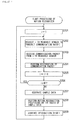
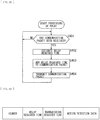
- This processing is started, for example, when the power of the wearable sensor 101 is turned on, and is finished when the power is turned off.
- step S1 the sensor data acquisition section 139 starts acquiring sensor data.
- the sensor data acquisition section 139 starts processing of acquiring HDR acceleration data, LDR acceleration data, HDR angular velocity data, and LDR angular velocity data from the HDR acceleration sensor 131, the LDR acceleration sensor 132, the HDR gyro sensor 133, and the LDR gyro sensor 134, respectively; adding the acquired time to the acquired data; and supplying the resulting acquired data to the merge processing section 140.
- the sensor data acquisition section 139 starts processing of acquiring geomagnetic data from the geomagnetic sensor 135, adding the acquired time to the acquired data, and supplying the resulting acquired data to the posture detection section 141.
- the sensor data acquisition section 139 starts processing of acquiring strain data and barometric pressure data from the strain sensor 136 and the barometric sensor 137, respectively, adding the acquired time to the acquired data, and supplying the resulting acquired data to the correction section 142.
- step S2 the merge processing section 140 starts merging processing of the acceleration data and the angular velocity data.
- the merge processing section 140 starts processing of merging (synthesizing) the HDR acceleration data and the LDR acceleration data, and supplying the merged acceleration data to the buffer 143 for accumulation.
- data based on the LDR acceleration data is used for data within the dynamic range of the LDR acceleration data, and data based on the HDR acceleration data is used for data outside the range.
- detection accuracy in the acceleration within the dynamic range of the LDR acceleration data is improved in the merged acceleration data.
- the merge processing section 140 starts processing of merging (synthesizing) the HDR angular velocity data and the LDR angular velocity data, and supplying the merged angular velocity data to the buffer 143 for accumulation.
- data based on the LDR angular velocity data is used for data within the dynamic range of the LDR angular velocity data
- data based on the HDR angular velocity data is used for data outside the range.
- the posture detection section 141 starts detecting a posture. Specifically, the posture detection section 141 starts processing of detecting Euler angles around three axes, i.e., around the pitch axis, around the roll axis, and around the yaw axis, which indicate postures of the detection points, on the basis of the acceleration data, the angular velocity data, and the geomagnetic data. In addition, the posture detection section 141 starts processing of supplying posture data indicating the detection results to the buffer 143 for accumulation.
- step S4 the correction section 142 starts correcting the strain data and the barometric pressure data.
- the correction section 142 starts processing of removing noises of the strain data and the barometric pressure data, converting data sizes, and the like.
- the correction section 142 starts processing of supplying the corrected strain data and barometric pressure data to the buffer 143 for accumulation.
- step S5 the packet generation section 144 determines whether or not it is a timing to transmit a communication packet. This determination processing is repeatedly executed until it is determined to be a timing to transmit the communication packet; in a case where it is determined to be a timing to transmit the communication packet, the processing proceeds to step S6.
- the communication packet is transmitted at predetermined intervals.
- the communication packet is transmitted at a frequency of transmission of 128 Hz (i.e., 128 times per second).
- the sampling frequency of the motion detection data included in the communication packet is 128 Hz.
- the packet generation section 144 generates a communication packet. For example, the packet generation section 144 reads out the latest posture data, acceleration data, angular velocity data, strain data, and barometric pressure data from the buffer 143. In addition, the packet generation section 144 acquires time information indicating the current time from the time information acquisition section 138. Then, the packet generation section 144 generates a communication packet including the posture data, the acceleration data, the angular velocity data, the strain data, and the barometric pressure data read out from the buffer 143.
- FIG. 7 illustrates an example of a format of a communication packet generated by the packet generation section 144.
- the communication packet includes a header, a time stamp, and motion detection data.
- time at which the sensor data is acquired is set in the time stamp. It is to be noted that the time at which the sensor data is acquired is set to, for example, the earliest of acquisition times of the respective sensor data used for the motion detection data in the communication packet.
- the time stamp (time at which the sensor data is acquired) may be stored in the communication packet for each data.
- the format of the communication packet is, for example, a header, a time stamp 1, data 1 (e.g., posture data) included in the motion detection data, time stamp 2, data 2 (e.g., acceleration data) included in the motion detection data, and so on.
- the motion detection data includes posture data, acceleration data, angular velocity data, strain data, and barometric pressure data read out from the buffer 143. It is to be noted that the motion detection data is encrypted by a predetermined method, for example.
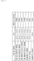
- FIG. 8 illustrates an example of specifications of each data included in the motion detection data.
- the size of the posture data is set to, for example, 16 bits ⁇ 3 axes.
- the frequency with which the communication packet is transmitted is 128 Hz
- the sampling frequency of the posture data is 128 Hz
- the bit rate thereof is 6,144 bps (bit per second).
- the size of the acceleration data is, for example, 20 bits ⁇ 3 axes.
- the frequency with which the communication packet is transmitted is 128 Hz
- the sampling frequency of the acceleration data is 128 Hz
- the bit rate thereof is 7,680 bps.
- the size of the angular velocity data is, for example, 20 bits ⁇ 3 axes.
- the sampling frequency of the angular velocity data is 128 Hz, and the bit rate thereof is 7,680 bps.
- the size of the strain data is, for example, 16 bits ⁇ 2 axes.
- the sampling frequency of the strain data is 128 Hz
- the bit rate thereof is 4,096 bps.
- the size of the barometric pressure data is, for example, 24 bits.
- the frequency with which the communication packet is transmitted is 128 Hz
- the sampling frequency of the barometric pressure data is 128 Hz
- the bit rate thereof is 2,048 bps.
- the packet generation section 144 supplies the communication packet to the transmission control section 145. Further, the packet generation section 144 deletes, from the buffer 143, each data transmitted by a communication packet and data older than each data.
- step S7 the transmission section 146 transmits a communication packet to the motion recognizer 102 under the control of the transmission control section 145.
- step S5 processing from step S5 onward is executed.
- step S31 the reception section 161 starts receiving a communication packet. That is, the reception section 161 starts processing of receiving a communication packet transmitted from each wearable sensor 101 and supplying the received communication packet to the packet restoration section 162.
- step S32 the packet restoration section 162 starts restoring the communication packet. For example, after performing decoding, etc. of the motion detection data included in the communication packet received from each wearable sensor 101, the packet restoration section 162 starts processing of associating the motion detection data with the time stamp included in the communication packet, and supplying the associated motion detection data to the buffer 163 for accumulation.
- step S33 the sample data generation section 164 determines whether or not it is a timing to perform the motion recognition processing. This determination processing is repeatedly executed until it is determined to be a timing to perform the motion recognition processing; in a case where it is determined to be a timing to perform the motion recognition processing, the processing proceeds to step S34.
- the motion recognition processing is performed at predetermined intervals.
- the motion recognition processing is executed with the same frequency as the frequency with which the communication packet is transmitted (e.g., 128 times per second).
- step S34 the sample data generation section 164 extracts motion detection data having a close time stamp.
- the sample data generation section 164 detects a time zone in which the time stamp of the motion detection data of all the detection points falls within a range of predetermined time period (e.g., several milliseconds) while going back from the current time to the previous time. Then, the sample data generation section 164 extracts the motion detection data with the time stamp included in the time zone. As a result, pieces of motion detection data having a close time stamp are extracted one by one for the respective detection points. That is, pieces of the motion detection data corresponding to the movements detected at substantially the same timing at the respective detection points are extracted.
- a range of predetermined time period e.g., several milliseconds
- a time zone in which the number of the detection data is maximized may be detected to extract the motion detection data in that time zone.
- the motion detection data of some of the detection points is lost.
- the width of the time zone in which the motion detection data is extracted may be widened to allow the motion detection data of all the detection points to be extracted.
- step S35 the sample data generation section 164 generates sample data using the extracted motion detection data. Specifically, the sample data generation section 164 generates sample data including the motion detection data of the respective detection points extracted in the processing of step S34, and supplies the sample data to the motion recognition section 165. In addition, the sample data generation section 164 deletes, from the buffer 163, the extracted motion detection data and the motion detection data with the time stamp being older than that of the extracted motion detection data.
- step S36 the motion recognition section 165 performs the motion recognition processing on the basis of the sample data.
- the motion recognition section 165 recognizes, using the motion recognition model, the motion of the user on the basis of the postures, accelerations, angular velocities, strains (expansion and contraction), and barometric pressures (heights) of the respective detection points of the user.
- the motion recognition model is, for example, a model that performs the motion recognition of a user on the basis of a motion relationship among the respective detection points of the user (e.g., interlocking property among the respective detection points, etc.).
- the motion recognition model is generated by, for example, preliminary learning processing. It is possible to adopt, as a learning method of the motion recognition model, any method such as a recursive neural network (RNN).
- RNN recursive neural network
- the motion recognition section 165 supplies the results of the motion recognition of the user to the transmission control section 166.
- step S37 the motion recognizer 102 transmits the recognition results.
- the transmission control section 166 generates motion control data on the basis of the results of the motion recognition of the user, and supplies the motion control data to the transmission section 167.
- the motion control data includes, for example, at least one of the results of the motion recognition of the user or control information on processing corresponding to the recognized motion.
- the motion control data may include motion detection data of respective detection points used for motion recognition. This makes it possible to detect details of the recognized motion on the basis of the motion detection data in an apparatus in a subsequent stage.
- the transmission section 167 transmits the motion control data to an apparatus in a subsequent stage, for example, a smartphone, a personal computer, various systems, or the like.
- the transmission of the motion control data may be performed by intermittent transmission.
- the motion control data may be transmitted at a timing at which the results of the motion recognition change. This makes it possible to reduce the power consumption of the motion recognizer 102.
- a general-purpose protocol such as HID (Human Interface Device) or MIDI (Music Instrument Digital Interface) may be used as a transmission protocol of the motion control data.
- HID Human Interface Device
- MIDI Music Instrument Digital Interface
- step S33 the processing returns to step S33, and the processing from step S33 onward is executed.
- the motion recognition system 100 recognizes types of motion of the user (e.g., information on meaning of the motion), but does not further perform recognition of a detailed movement of each motion.
- the number of the wearable sensors 101 attached may be reduced by thus limiting to types of motions of the user based on predetermined classification. As a result, it is possible to reduce the burden on the user as compared with an existing motion capture system used in CG (Computer Graphics) or the like. For example, even when the user wears the wearable sensor 101, it is possible for the user to perform substantially usual movement with little restriction on the movement.
- CG Computer Graphics
- the types of motions are recognized and outputted, and thus the burden on the developer of the application programs is reduced.
- the camera it is possible to perform motion recognition without paying attention to the installation position, the filming range, the filming condition, and the like of the camera.
- the user who is a recognition target it is possible for the user who is a recognition target to wear clothes or costumes of a desired color or design without paying attention to the relationship with the set of stages, the background, or the like.
- the position at which the camera is installed is not limited by structure, rendering, or the like of the stage, and as a result a range in which the motion of the user is recognizable is not limited.
- the motion recognition system 100 for each user, it is possible to individually recognize the motions of each user without being influenced by other users. For example, it is possible, in a dance performance in a group, to recognize the motion of an individual performer, or the motion of a specific performer.
- sampling frequencies of the respective sensors of the wearable sensor 101 are higher than the frame rate of a typical camera, thus making it possible to recognize higher-speed motions of the user. For example, it is possible to accurately recognize high-speed movements such as dance turns and steps.
- a camera may be provided in the motion recognition system 100 and the position of the user may be detected on the basis of an image filmed by the camera.
- at least one of the wearable sensors 101 may be provided with a device that is able to detect position information of the user, such as a GNSS (Global Navigation Satellite System) receiver to allow for detection of the position of the user.
- GNSS Global Navigation Satellite System
- FIG. 13 illustrates a configuration example of a learning system 200 which is an embodiment of a learning system to which the present technology is applied. It is to be noted that, in the diagram, parts corresponding to those of the motion recognition system 100 in FIG. 1 are denoted by the same reference numerals and descriptions thereof are omitted as appropriate.
- the learning system 200 is a system that performs learning processing of the motion recognition model to be applied to the motion recognition section 165 of the motion recognizer 102.
- the learning system 200 includes the wearable sensor 101-1 to the wearable sensor 101-6 and a learning processor 201.
- the learning processor 201 performs learning processing of the motion recognition model on the basis of motion detection data included in a communication packet transmitted from each wearable sensor 101.
- FIG. 14 illustrates a configuration example of an information processor 220 applicable to the learning processor 201 in FIG. 13 .
- the information processor 220 is configured by, for example, a personal computer, a smart phone, a tablet, or the like.
- the information processor 220 includes a CPU (Central Processing Unit) 221, a ROM (Read Only Memory) 222, a RAM (Random Access Memory) 223, a bus 224, an input/output interface 225, an input unit 226, an output unit 227, a storage unit 228, a communication unit 229, a drive 230, and a removable medium 231.
- a CPU Central Processing Unit
- ROM Read Only Memory
- RAM Random Access Memory
- the CPU 221, the ROM 222 and the RAM 223 are coupled to one another by a bus 224.
- the input/output interface 225 is further coupled to the bus 224.
- the input unit 226, the output unit 227, the storage unit 228, the communication unit 229, and the drive 230 are coupled to the input/output interface 225.
- the input unit 226 includes, for example, a keyboard, a mouse, a microphone, and the like.
- the output unit 227 includes, for example, a display, a speaker, and the like.
- the storage unit 228 includes, for example, a hard disk, a non-volatile memory, and the like.
- the communication unit 229 includes, for example, a wireless or wired communication device, a network interface, and the like.
- the drive 230 drives a removable medium 231 such as a magnetic disk, an optical disk, a magneto-optical disk, or a semiconductor memory.
- the CPU 221 loads a program stored in, for example, the storage unit 228 into the RAM 243 via the input/output interface 225 and the bus 224, and executes the program to thereby perform various types of processing.
- the programs executed by the information processor 220 may be provided by being recorded in the removable medium 231 as a package medium or the like, for example.
- the program may also be provided via a wired or wireless transmission medium, such as a local area network, the Internet, or digital satellite broadcasting.
- a program may be installed in the storage unit 228 via the input/output interface 225 by mounting the removable medium 231 in the drive 230.
- the program may also be received by the communication unit 229 via a wired or wireless transmission medium and installed in the storage unit 228.
- the program may be installed in advance in the ROM 202 or the storage unit 228.
- bus 224 and the input/output interface 225 are omitted as appropriate.
- description is simply given to the effect that the CPU 221 and the communication unit 229 transmit and receive data.
- FIG. 15 illustrates a configuration example of a learning processing unit 251 achieved by the CPU 221 of the information processor 220 executing a predetermined control program.
- the learning processing unit 251 includes a packet restoration section 261, a buffer 262, a sample data generation section 263, a buffer 264, a learning data generation section 265, a learning section 266, and a UI (user interface) control section 267.
- the packet restoration section 261 restores a communication packet of each wearable sensor 101, associates motion detection data included in a communication packet with a time stamp, and supplies the associated motion detection data to the buffer 262.
- the buffer 262 temporarily accumulates the motion detection data extracted from the communication packet of each wearable sensor 101.
- the sample data generation section 263 generates sample data using the motion detection data accumulated in the buffer 262, and supplies the sample data to the buffer 264.
- the buffer 264 temporarily accumulates the sample data.
- the learning data generation section 265 generates learning data by adding a label to the sample data accumulated in the buffer 264, and supplies the learning data to the learning section 266.
- the label indicates, for example, types of motions of the user at the time when the motion detection data included in the sample data is detected.
- the learning section 266 performs learning processing of a motion recognition model on the basis of the learning data. It is to be noted that any learning method may be adopted for the learning processing of the motion recognition model.
- the UI control section 267 controls the output unit 227 on the basis of user input or the like inputted via the input unit 226, and controls the user interface at the time of performing the learning processing of the motion recognition mode.
- the motion registration processing is processing of registering a motion to be newly recognized in the motion recognition model.
- description is given, as an example, of a case where a new dance technique is registered as a recognition target.
- step S101 the learning processing unit 251 receives selection of a point of interest.
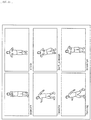
- the output unit 227 displays a window W1 in FIG. 17 under the control of the UI control section 267.
- the window W1 locations (detection points) where the user wears the wearable sensor 101 are indicated by circles. Then, the user selects a point of interest from among the detection points via the input unit 226.
- the point of interest refers to a detection point (location) of particular interest in a motion to be registered.
- a detection point in a location that particularly remarkably represents a feature of the motion to be registered is selected as the point of interest. Then, for example, in the learning processing, the movement of the point of interest is emphasized more than the movements of other detection points.
- both wrists are selected as the point of interests.
- the UI control section 267 acquires selection results of the points of interest from the input unit 226, and supplies the selection results to the learning section 266.
- step S102 the learning processing unit 251 accepts setting of a tempo.
- the output unit 227 displays a window W2 in FIG. 17 under the control of the UI control section 267.
- the window W2 displays a slider 281 for setting of the tempo of a clicking sound upon registering motions.
- the user sets the tempo upon registering the motions by moving the slider 281 left and right via the input unit 226.
- the tempo is set to 120 bpm (beats per minute).
- the UI control section 267 acquires setting results of the tempo from the input unit 226.
- step S103 the learning processing unit 251 receives setting of a timing for registering motions.
- the output unit 227 displays a window W3 in FIG. 17 under the control of the UI control section 267.
- the window W3 displays circled numbers 1 to 4 indicating four-beat clicking sounds. It is to be noted that, in the window W3 and windows W5 and W6 to be described later, characters such as "beep" over the circled number indicate clicking sounds to be outputted in respective beats, and are not actually displayed.
- the user sets a timing for registration of motions via the input unit 226.
- the motion is set to be registered between clicking sounds of the first beat and the second beat. That is, a period from the output of the clicking sound of the first beat to the output of the clicking sound of the second beat is set as a registration period of the motion.
- a sound volume of the clicking sounds of the first beat and the second beat becomes large, and a sound volume of the clicking sounds of the third beat and the fourth beat becomes small.
- the UI control section 267 acquires setting results of the tempo from the input unit 226.
- step S104 the motion recognition system 100 accepts registration of motions.
- the output unit 227 displays a window W4 in FIG. 17 under the control of the UI control section 267, and presents a timing at which the registration of the motions is started. Then, under the control of the UI control section 267, the output unit 227 displays a window W5 in FIG. 17 at the period of time when the registration of the motions is started, and starts outputting the clicking sound at the set tempo.
- the sound volume of the clicking sound becomes large in the first beat and the second beat, and sound volume of the clicking sound becomes small in the third beat and the fourth beat.
- some of the wearable sensors 101 may have a built-in speaker to output a clicking sound from the speaker.
- the user performs a motion to be registered during a motion registration period between clicking sounds of the first beat and the second beat while wearing the wearable sensor 101.
- the user starts the motion when the clicking sound of the first beat is outputted, and finishes the motion when the clicking sound of the second beat is outputted.
- This enables the user to reliably input motions into the learning system 200.
- this enables the user to register motions while having fun in a game feeling.
- the clicking sound may be outputted in accordance with a desired music piece of the user to allow the user to register motions while having more fun.
- Each wearable sensor 101 starts processing of transmitting a communication packet including motion detection data indicating the movement of each of the detection points at a predetermined cycle by the processing described above with reference to FIG. 6 .
- the communication unit 229 of the information processor 220 (learning processor 201) starts processing of receiving a communication packet from each wearable sensor 101 and providing the communication packet to the packet restoration section 261.
- the packet restoration section 261 starts processing of restoring the communication packet of each wearable sensor 101, associating the motion detection data included in the communication packet with the time stamp, and supplying the associated motion detection data to the buffer 262 for accumulation.
- the sample data generation section 263 starts processing of generating sample data using the motion detection data accumulated in the buffer 262, and supplying the sample data to the buffer 264 for accumulation. It is to be noted that, at this time, for example, sample data is generated using only motion detection data detected between clicking sounds of the first beat and the second beat.
- step S105 the learning processing unit 251 learns the motions. Specifically, the learning data generation section 265 starts processing of generating learning data by adding a label indicating types of motions to be newly registered in the sample data accumulated in the buffer 264 and supplying the learning data to the learning section 206.
- the learning section 206 starts learning processing for registration of a new motion in the motion recognition model on the basis of the acquired learning data. At this time, in a case where points of interest are selected, for example, the learning section 206 performs the learning processing by giving larger weight to the motion detection data of the points of interest than weight to the motion detection data of other detection points. That is, the learning section 206 performs learning processing by giving weights to the respective detection points.
- the output unit 227 displays a window W6 in FIG. 17 under the control of the UI control section 267, notifies the completion of the registration of the motion, and outputs a clicking sound of "beeep" which differs from the clicking sound at the time of registration.
- the information processor 220 presents reliability.
- the learning section 206 calculates the reliability of the currently registered motion by a predetermined method.
- the reliability of the motion is calculated on the basis of, for example, an amount of learning data used for registration of the motion, variance of sample data included in the learning data, probability of erroneously determining to be another motion, and the like.
- the output unit 227 displays a window W7 in FIG. 17 under the control of the UI control section 267, and presents reliability of the currently registered motions. Further, in a case where the reliability of the motion is not sufficient, for example, a message is displayed to the effect that a little more learning data is necessary. This enables the user, for example, to make determination as to whether or not more learning is necessary, or whether or not to change the motion in order to clarify the difference from other motions.
- FIG. 18 illustrates an example in which genre of dances is organized.
- the genre of dances is represented by a hierarchical structure. That is, the lower the genre in the diagram is, the older the occurrence time is; the higher the genre is, the newer the occurrence time is. Then, a new genre is created on the basis of the old genre.
- combining or refining the techniques of the old genre creates some of the techniques of a new genre. Therefore, a feature of the dance technique of the old genre is included in a portion of the technique of the new genre. Therefore, the older the genre is, the greater the influence on other genres becomes; the newer the genre is, the smaller the influence on other genres becomes.
- Jazz, Rock, Pop, and Break are genres each created on the basis of Soul.
- Middle School is a genre created on the basis of Jazz, Rock, Pop, and Break.
- Girls and House are genres each created on the basis of Middle School.
- New School is a genre created on the basis of Girls and House.
- dance techniques may also be represented by a hierarchical structure as illustrated in FIG. 19 .
- FIG. 19 relationships among dance techniques are indicated by arrows. That is, among the techniques connected by the arrows, the original technique of the arrow is influenced by the technique of the point of the arrow. For example, jerk is influenced by slide and worm. More specifically, a technique that combines slide and worm is jerk.
- a real-time motion property in the motion recognition is sometimes required depending on cases of using the results of the motion recognition.
- a delay time there are cases where it is required to shorten the time required from the time when a user performs a certain motion to the time when the motion recognition is performed (hereinafter, referred to as a delay time) as much as possible.
- Examples of the above-mentioned cases include a case where stage rendering is performed to follow the movement of a performer, a case where recognition results of the movement of a player is immediately fed back in a training of sports, etc., and a case where commands are inputted by the movements of a player in a game in which the real-time property is emphasized.
- the motion recognition section 165 of the motion recognizer 102 performs the motion recognition of the user on the basis of the motion of the plurality of detection points of the user. Therefore, even when the communication packets of some detection points are lost, and the movements of the detection points are not notified, it is often the case that it is possible to accurately recognize the motion of the user on the basis of the movements of other detection points.
- the learning system 200 learns the motion recognition model on the assumption that the communication packet (motion detection data) is lost, and the motion recognition system 100 limits the number of retransmissions of the communication packet.
- the learning section 266 of the learning system 200 it is conceivable to perform learning processing of the motion recognition model using learning data having partially lost motion detection data of respective detection points, in accordance with a method such as dropout.
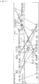
- FIG. 20 illustrates some of examples of such learning data.
- FIG. 20 illustrates an example of waveforms of angular velocity data and acceleration data among the motion detection data of the respective detection points included in the learning data.
- the horizontal axis represents time
- the vertical axis represents angular velocity or acceleration.
- the waveforms of the angular velocity data and the waveforms of the acceleration data at the respective detection points are substantially the same; however actually, the waveforms are different between the respective detection points.
- the hatched parts of the respective graphs in the diagram indicate parts in which motion detection data is lost.
- a motion recognition model that is robust against the loss of the motion detection data is constructed.
- the number of retransmissions of the communication packet between each wearable sensor 101 and the motion recognizer 102 is limited by using the motion recognition model that is robust against the loss of motion detection data.
- transmission interval of the communication packet is about 7.8 milliseconds.
- the number of retransmissions of the communication packet and the loss rate of motion detection data are in a trade-off relationship.
- the loss rate of motion detection data and the motion recognition accuracy are also in a trade-off relationship.
- FIG. 21 is a graph illustrating a relationship between the loss rate of motion detection data and the motion recognition accuracy (F value).
- the horizontal axis represents the data loss rate (unit: %), and the vertical axis represents the recognition accuracy.
- FIG. 22 illustrates an example of a relationship among the upper limit value of the number of retransmissions of the communication packet, the loss rate of the motion detection data, the maximum delay time of the communication packet, and the recognition accuracy (F value) in the motion.
- the loss rate of the motion detection data is 2.5%
- the maximum delay time is 11.7 milliseconds
- the motion recognition accuracy is 0.90.
- the loss rate of the motion data increases to 5.0%, and the motion recognition accuracy decreases to 0.85. Meanwhile, the maximum delay time is reduced to 7.8 milliseconds.
- the loss rate of the motion data increases to 8.0%, and the motion recognition accuracy decreases to 0.80. Meanwhile, the maximum delay time is reduced to 3.9 milliseconds.
- the number of retransmissions of the communication packet is limited to one. This makes it possible to achieve an application that follows the motion of the user quickly, although the motion recognition accuracy is somewhat lowered.
- the number of retransmissions of the motion is increased to three. This makes it possible to improve the motion recognition accuracy of the user, and thus to achieve an application that more appropriately follows the motion of the user.
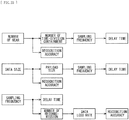
- examples of factors contributing to the real-time property of the motion recognition include the number of the wearable sensors 101 attached, the size of motion detection data, and the sampling frequency of motion detection data (the frequency with which the communication packet is transmitted), as illustrated in FIG. 23 .
- the number of wearable sensor 101 attached when the number of wearable sensor 101 attached is reduced, the number of the time-division containment is reduced, thus making it possible to increase the sampling frequency of the motion detection data (the frequency with which the communication packet is transmitted) without changing the number of retransmissions of the communication packet. As a result, the cycle of the motion recognition processing is shortened and the delay time is reduced, thus improving the real-time property of the motion recognition.
- the number of the wearable sensors 101 attached is reduced, the number of detection points is reduced, thus lowering the motion recognition accuracy. Conversely, when the number of the wearable sensors 101 attached is increased, the real-time property of the motion recognition is lowered, but the motion recognition accuracy is improved.
- the size of the motion detection data when the size of the motion detection data is reduced, payload size of the communication packet is reduced, thus making it possible to increase the sampling frequency of the motion detection data (frequency with which the communication packet is transmitted) without changing the number of retransmissions of the communication packet. As a result, the cycle of the motion recognition processing is shortened and the delay time is reduced, thus making it possible to improve the real-time property of the motion recognition.
- the size of the motion detection data is reduced, the size of each data included in the motion detection data is reduced, and the resolution of the acceleration, the angular velocity, and the like is lowered. As a result, the motion recognition accuracy is lowered. Conversely, when the size of the motion detection data is increased, the real-time property of the motion recognition decreases, but the motion recognition accuracy is improved.
- the sampling frequency of the motion detection data (frequency with which the communication packet is transmitted)
- the cycle of the motion recognition processing becomes shorter, and the delay time decreases, thus improving the real-time property of the motion recognition.
- the shorter transmission cycle of the communication packet it is necessary to reduce the number of retransmissions of the communication packet in a case where the delay time is tried to be contained within the transmission cycle of the communication packet.
- the data loss rate increases, and the motion recognition accuracy decreases.
- the sampling frequency of the motion detection data is lowered, the real-time property of the motion recognition is lowered, but the motion recognition accuracy is improved.
- the motion recognition system 100 it is desirable to be able to adjust one or more of the number of retransmissions of the communication packet, the number of the wearable sensors 101 attached, the size of the motion detection data, and the sampling frequency of the motion detection data, on the basis of which of the real-time property of the motion recognition and the motion recognition accuracy is emphasized.
- This enables the motion recognition system 100 to appropriately cope with both an application requiring the real-time property and an application requiring the recognition accuracy.
- the motion recognition is performed on the basis of the motion relationship between the detection points of the user. Accordingly, in order to improve the motion recognition accuracy, it is important to synchronize timings of detecting the movements of the respective detection points as much as possible. Alternatively, it is important to perform the motion recognition processing using the motion detection data detected at the respective detection points at the same timing as much as possible.
- the motion recognition processing is performed using the motion detection data detected at the respective detection points at the same time as much as possible on the basis of the time stamp of each communication packet.
- synchronization processing is required for the time between the time information acquisition sections 138 of the respective wearable sensors 101 by using some method.
- the synchronization processing at this time needs to be performed each time the power of each wearable sensor 101 is turned on, for example, thus causing high processing load.
- more complicated processing is required to cope with the out-of-sync of the time during use of the motion recognition system 100.
- the detection timings of the motion detection data of the respective detection points used in the motion recognition processing necessarily need not be strictly simultaneous; it is often the case that some degree of out-of-sync (e.g., in units of several milliseconds or within one sample) is allowed.
- the motion recognizer controls the timing at which each wearable sensor detects the motion detection data, thereby performing the motion recognition processing at each detection point using the motion detection data detected at the same timing as much as possible.
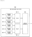
- FIG. 24 illustrates a configuration example of a motion recognition system 300 which is a second embodiment of the motion recognition system to which the present technology is applied.
- the motion recognition system 300 includes a wearable sensor 301-1 to a wearable sensor 301-6 and a motion recognizer 302.
- wearable sensor 301-1 to the wearable sensor 301-6 need not be individually distinguished, they are simply referred to as a wearable sensor 301.
- each wearable sensor 301 is attached to a different detection point of the user.
- Each wearable sensor 301 detects the movement of each detection point under the control of the motion recognizer 302, and transmits a communication packet including detection results to the motion recognizer 302.
- the motion recognizer 302 performs processing of motion recognition of the user on the basis of motion detection data of the detection points included in the communication packet received from each wearable sensor 301.
- the motion recognizer 302 transmits the motion control data based on results of the motion recognition of the user to an apparatus in a subsequent stage.
- FIG. 25 illustrates a configuration example of the wearable sensor 301 in FIG. 24 . It is to be noted that, in the diagram, parts corresponding to those of the wearable sensor 101 in FIG. 3 are denoted by the same reference numerals, and descriptions thereof are omitted as appropriate.
- the wearable sensor 301 differs from the wearable sensor 101 in that a packet generation section 331 and a transmission control section 334 are provided instead of the packet generation section 144 and the transmission control section 145, that a buffer 332 and a reception section 333 are added, and that the time information acquisition section 138 is deleted.
- the packet generation section 331 generates a communication packet for transmission of the motion detection data including posture data, acceleration data, angular velocity data, strain data, and barometric pressure data accumulated in the buffer 143, and supplies the communication packet to the buffer 332.
- the buffer 332 temporarily accumulates communication packets.
- the reception section 333 receives a transmission request signal requesting transmission of a communication packet from the motion recognizer 302 by wireless communication of the same system as the transmission section 146, and supplies the transmission request signal to the transmission control section 334.
- the transmission control section 334 controls the transmission of the communication packet by the transmission section 146.
- FIG. 26 illustrates a configuration example of the motion recognizer 302 in FIG. 24 . It is to be noted that, in the diagram, parts corresponding to those of the motion recognizer 102 in FIG. 5 are denoted by the same reference numerals, and descriptions thereof are omitted as appropriate.
- the motion recognizer 302 differs from the motion recognizer 102 in that a communication control section 361 and a transmission section 362 are added and the buffer 163 is deleted.
- the communication control section 361 generates a transmission request signal for requesting each wearable sensor 301 to transmit a communication packet, and supplies the transmission request signal to the transmission section 362. Further, the communication control section 361 supplies the communication packet from each wearable sensor 301 supplied from the reception section 161 to the packet restoration section 162.
- the transmission section 362 transmits the transmission request signal to each wearable sensor 301 by wireless communication of a system corresponding to the reception section 333 of each wearable sensor 301.
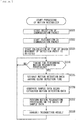
- This processing is started, for example, when the power of the motion recognizer 302 is turned on, and is finished when the power is turned off.
- step S201 the communication control section 361 sets the value of a variable i to one.
- step S202 the motion recognizer 302 requests an i-th wearable sensor (wearable sensor 301-i) to transmit a communication packet.
- the communication control section 361 generates a transmission request signal for requesting the wearable sensor 301-i to transmit a communication packet, and supplies the transmission request signal to the transmission section 362.
- the transmission section 362 transmits the transmission request signal to the wearable sensor 301-i.
- the wearable sensor 301-i receives the transmission request signal in step S236 in FIG. 28 described later, and transmits the communication packet in step S237.
- step S203 the reception section 161 receives the communication packet from the i-th wearable sensor (wearable sensor 301-i).
- the reception section 161 supplies the received communication packet to the communication control section 361.
- the communication control section 361 supplies the communication packet to the packet restoration section 162.
- the packet restoration section 162 restores the communication packet.
- the packet restoration section 162 performs decoding, etc. of the motion detection data included in the acquired a communication packet, and then supplies the motion detection data to the sample data generation section 164.
- step S205 the communication control section 361 increments the value of the variable i by one.
- step S206 the communication control section 361 determines whether or not the value of the variable i is equal to or smaller than a constant M.
- the processing returns to step S202.
- step S202 to step S206 processing in step S202 to step S206 is repeatedly executed until it is determined in step S206 that the value of the variable i exceeds the constant M.
- step S206 processing in step S202 to step S206 is repeatedly executed until it is determined in step S206 that the value of the variable i exceeds the constant M.
- a subsequent wearable sensor 301 may be requested to transmit the communication packet.
- step S206 determines that the value of the variable i exceeds the constant M.
- step S207 the sample data generation section 164 generates sample data. That is, the sample data generation section 164 generates the sample data including the motion detection data from the wearable sensor 301 supplied from the packet restoration section 162. The sample data generation section 164 supplies the generated sample data to the motion recognition section 165.
- steps S208 and S209 processing similar to those in steps S36 and S37 in FIG. 9 is executed. Thereafter, the processing returns to step S201, and processing from step S201 onward is executed.
- This processing is started, for example, when the power of the wearable sensor 301 is turned on, and is finished when the power is turned off.
- steps S231 to S234 processing similar to those in steps S1 to S4 in FIG. 6 is performed.
- step S235 the packet generation section 331 starts generating a communication packet. Specifically, the packet generation section 331 starts processing of reading out the latest posture data, acceleration data, angular velocity data, strain data, and barometric pressure data from the buffer 143, generating a communication packet including the read data, and accumulating the communication packet in the buffer 332.
- FIG. 29 illustrates an example of a format of the communication packet generated by the packet generation section 331.
- This communication packet differs from the communication packet in FIG. 7 in that the time stamp is deleted. That is, the motion recognizer 302 controls a timing at which each wearable sensor 301 transmits a communication packet, thus making the time stamp unnecessary.
- step S236 the transmission control section 334 determines whether or not transmission of the communication packet has been requested. This determination processing is repeatedly executed at a predetermined timing until it is determined that the transmission of the communication packet has been requested.
- the transmission control section 334 determines that the transmission of the communication packet has been requested, and the processing proceeds to step S237.
- step S237 the wearable sensor 301 transmits a communication packet.
- the transmission control section 145 reads out the communication packet from the buffer 332 and supplies the communication packet to the transmission section 146.
- the transmission control section 145 deletes the read communication packet from the buffer 332.
- the transmission section 146 transmits the communication packet to the motion recognizer 302.
- FIG. 30 is a sequence diagram illustrating communication between the motion recognizer 302 and each wearable sensor 301 in the processing of FIGs. 27 and 28 .
- the motion recognizer 302 transmits a transmission request signal (REQ) to each of the wearable sensors 301 in sequence, and the respective wearable sensors 301 transmit communication packets (ACK) in sequence. Accordingly, it is possible to adjust detection timings of the motion detection data of the respective wearable sensors 301 used in the motion recognition processing without using a synchronization signal, a time stamp, or the like. Accordingly, it is possible to improve the accuracy in the motion recognition processing. Further, in the motion recognizer 302, the processing of buffering and waiting the communication packet until the communication packets from the respective wearable sensors 301 are arranged becomes unnecessary.
- REQ transmission request signal
- ACK communication packets
- the motion recognizer 302 After receiving the communication packet from each wearable sensor 301, the motion recognizer 302 generates a sample data, and executes the motion recognition processing. For example, in a case where the motion recognition processing is performed 128 times per second, the above processing is executed at a cycle of 7.8 milliseconds.
- the wearable sensor 301 may generate the communication packet and transmit the generated communication packet when receiving transmission request information from the motion recognizer 302.
- the motion recognition processing is performed using the motion detection data detected at respective detection points at the same timing as much as possible by a method different from the second embodiment.
- FIG. 31 illustrates a configuration example of a motion recognition system 400 which is a third embodiment of the motion recognition system to which the present technology is applied.
- the motion recognition system 400 includes a wearable sensor 401-1 to a wearable sensor 401-6, and a motion recognizer 402.
- wearable sensor 401-1 to the wearable sensor 401-6 need not be individually distinguished, they are simply referred to as a wearable sensor 401.
- each wearable sensor 401 is attached to a different detection point of the user, detects the movement of each detection point, and transmits a communication packet including detection results to the motion recognizer 402.
- the motion recognizer 402 performs processing of the motion recognition of the user on the basis of motion detection data of each detection point included in the communication packet received from each wearable sensor 401.
- the motion recognizer 402 transmits the motion control data based on results of the motion recognition of the user to an apparatus in a subsequent stage.
- FIG. 32 illustrates a configuration example of the wearable sensor 401 in FIG. 31 .
- parts corresponding to those of the wearable sensor 101 in FIG. 3 are denoted by the same reference numerals, and descriptions thereof are omitted as appropriate.
- the wearable sensor 401 differs from the wearable sensor 101 in that a packet generation section 433 is provided instead of the packet generation section 144, and a clock generation section 431 and a required time estimation section 432 are added.
- the clock generation section 431 generates a clock signal of a predetermined frequency, and supplies the clock signal to each section of the wearable sensor 401 such as the required time estimation section 432. It is to be noted that, the clock generation section 431 is provided in the wearable sensor 101 in FIG. 3 and the wearable sensor 301 in FIG. 25 , but illustration thereof is omitted because the illustration is not particularly necessary for description of the processing.
- the required time estimation section 432 reads out, from the buffer 143, posture data, acceleration data, angular velocity data, strain data, and barometric pressure data to be transmitted to the motion recognizer 402, and supplies the pieces of data to the packet generation section 433.
- the required time estimation section 432 estimates time required for transmission (hereinafter, referred to as transmission required time) of the data on the basis of the clock signal, and supplies information indicating estimation results to the packet generation section 433.
- Packet generation section 433 generates a communication packet for transmission of data supplied from the required time estimation section 432, and supplies the communication packet to the transmission control section 145.
- FIG. 33 illustrates a configuration example of the motion recognizer 402 in FIG. 31 . It is to be noted that, in the diagram, parts corresponding to those of the motion recognizer 102 in FIG. 5 are denoted by the same reference numerals, and descriptions thereof are omitted as appropriate.
- the motion recognizer 402 differs from the motion recognizer 102 in that a time information acquisition section 461 and a detection time calculation section 462 are added.
- the time information acquisition section 461 is configured by, for example, a clock, etc., and acquires time information indicating the current time and supplies the acquired time information to the detection time calculation section 462.
- the detection time calculation section 462 acquires, from the packet restoration section 162, the motion detection data and the transmission required time included in the communication packet received from each wearable sensor 401. Then, the detection time calculation section 462 calculates time at which the movement of a detection point corresponding to the motion detection data is detected (hereinafter, referred to as motion detection time) on the basis of the current time and the transmission required time. The detection time calculation section 462 associates the motion detection data with the motion detection time, and supplies the associated data to the buffer 163.
- This processing is started, for example, when the power of the wearable sensor 401 is turned on, and is finished when the power is turned off.
- steps S301 to S304 processing similar to those in steps S1 to S4 in FIG. 6 is performed.
- step S305 the required time estimation section 432 determines whether or not it is a timing to transmit a communication packet. This determination processing is repeatedly executed until it is determined to be a timing to transmit the communication packet; in a case where it is determined to be a timing to transmit the communication packet, the processing proceeds to step S306.
- step S306 the required time estimation section 432 estimates the transmission required time. Specifically, the required time estimation section 432 reads out the latest posture data, acceleration data, angular velocity data, strain data, and barometric pressure data from the buffer 143 as data to be transmitted to the motion recognizer 402. Then, the required time estimation section 432 estimates the transmission required time required for transmission of the motion detection data including such data.
- the transmission required time is, for example, required time from the time when the movement of the detection point is detected to the time when the communication packet including the motion detection data corresponding to the detected movement arrives at the motion recognizer 402.
- the time at which the movement of the detection point is detected is, for example, the time at which detection of the movement of the detection point is started. More specifically, for example, the motion detection time is acquisition time of sensor data first acquired by the sensor data acquisition section 139, among sensor data to be used for the motion detection data. For example, as the motion detection data, sensor data of each of HDR acceleration data, LDR acceleration data, HDR angular velocity data, LDR angular velocity data, geomagnetic data, strain data, and barometric pressure data are used. Then, the earliest time among the acquisition time of each sensor data used for the motion detection data to be transmitted to the motion recognizer 402 is set as the motion detection time.
- the required time estimation section 432 estimates time required from the time when the movement of the detection point is detected to the time when the communication packet including the motion detection data corresponding to the detected movement is generated (hereinafter, referred to as packet generation period).
- the packet generation period is, for example, a time period between the time at which the detection of the movement of the detection point is started (motion detection time) and the time at which the generation of the communication packet including the motion detection data corresponding to the detected motion is completed (hereinafter, referred to as packet generation time).
- the required time estimation section 432 calculates the packet generation period on the basis of the size, etc. of each sensor data using a predetermined calculation formula.
- the calculation formula for the packet generation period is prepared in advance on the basis of, for example, a timing at which the sensor data acquisition section 139 acquires the sensor data, a processing content from the acquisition of the sensor data to the generation of the communication packet, processing capability of the wearable sensor 401, and the like.
- the required time estimation section 432 estimates time required from the generation of the communication packet to the arrival of the communication packet at the motion recognizer 402 (hereinafter, referred to as packet transmission time).
- the packet transmission time is, for example, time between the packet generation time and the time at which the communication packet arrives at the motion recognizer 402 (hereinafter, referred to as packet arrival time).
- the required time estimation section 432 calculates the packet transmission time on the basis of communication packet size, communication status between the wearable sensor 401 and the motion recognizer 402, and the like, using a predetermined calculation formula.
- the calculation formula for the packet transmission time is prepared in advance on the basis of, for example, a communication method and a communication path between the wearable sensor 401 and the motion recognizer 402, processing capability of the wearable sensor 401 and the motion recognizer 402, and the like.
- the packet transmission time may be calculated on the basis of an actual measurement time in a case where the communication packet is transmitted and received in advance between the wearable sensor 401 and the motion recognizer 402.
- the required time estimation section 432 adds the packet generation period and the packet transmission time to calculate the transmission required time.
- time required for the retransmission is also added to the transmission required time. For example, time required for detection of the communication error, waiting time until retransmission is performed, time required for retransmission processing, and the like are added to the transmission required time.
- the required time estimation section 432 supplies posture data, acceleration data, angular velocity data, strain data, barometric pressure data, and estimation results of the transmission required time read out from the buffer 143 to the packet generation section 433. Further, the packet generation section 144 deletes each data transmitted by the communication packet and data older than that data from the buffer 143.
- step S307 the packet generation section 433 generates a communication packet.
- FIG. 35 illustrates an example of a format of the communication packet generated by the packet generation section 433.
- This communication packet differs from the communication packet in FIG. 7 in that transmission required time is included instead of a time stamp. That is, the transmission required time estimated by the required time estimation section 432 is included in the communication packet.
- the packet generation section 433 supplies the communication packet to the transmission control section 145.
- step S308 the transmission section 146 transmits the communication packet to the motion recognizer 402 under the control of the transmission control section 145.
- step S305 processing returns to step S305, and processing from step S305 onward is executed.
- This processing is started, for example, when the power of the motion recognizer 402 is turned on, and is finished when the power is turned off.
- step S331 the reception section 161 starts receiving a communication packet. That is, the reception section 161 starts processing of receiving a communication packet transmitted from each wearable sensor 401 and supplying the received communication packet to the packet restoration section 162.
- step S332 the packet restoration section 162 starts restoring the communication packet.
- the packet restoration section 162 performs decoding, etc. of the motion detection data included in the communication packet received from each wearable sensor 101, and then starts processing of supplying the restored communication packet to the detection time calculation section 462.
- step S333 the detection time calculation section 462 starts calculating the time at which the movement of the detection point is detected. Specifically, the detection time calculation section 462 starts calculating the time (motion detection time) at which the movement of the detection point corresponding to the motion detection data included in the communication packet supplied from the packet restoration section 162 is detected. Further, the detection time calculation section 462 starts processing of associating the motion detection data with the motion detection time, and supplying the associated motion detection data to the buffer 163 for accumulation.
- the detection time calculation section 462 estimates the time required from the time when the communication packet is received by the reception section 161 (from the time when the communication packet arrives at the motion recognizer 402) to the time when the communication packet is restored by the packet restoration section 162 (hereinafter, referred to as packet restoration time).
- the detection time calculation section 462 calculates the packet restoration time on the basis of the size, etc. of the communication packet using a predetermined calculation formula.
- the calculation formula for the packet restoration time is prepared in advance on the basis of, for example, the content of restoration processing of the communication packet, the processing capability of the motion recognizer 402, and the like.
- the detection time calculation section 462 acquires time information indicating the current time from the time information acquisition section 461, and calculates the motion detection time by subtracting the transmission required time included in the communication packet and the estimated packet restoration time from the current time.
- step S334 It is determined in step S334 whether or not it is a timing to perform the motion recognition processing, similarly to the processing in step S3 in FIG. 9 .
- This determination processing is repeatedly executed at a predetermined timing; in a case where it is determined to be a timing to perform the motion recognition processing, the processing proceeds to step S335.
- step S335 the sample data generation section 164 extracts motion detection data having close detection time. That is, the sample data generation section 164 uses the motion detection time instead of the time stamp to extract the motion detection data by a method similar to the processing of step S34 in FIG. 9 . As a result, pieces of motion detection data having close motion detection time are extracted one by one for the respective detection points. That is, pieces of the motion detection data corresponding to the movements detected at substantially the same timing at the respective detection points are extracted.
- steps S336 to S3308 processing similarto those in steps S35 to S37 in FIG. 9 is executed.
- step S334 the processing returns to step S334, and the processing from step S334 onward is executed.
- the motion recognizer 402 it is possible, in the motion recognizer 402, to easily and accurately detect the motion detection time. Then, the motion recognition processing is performed using the motion detection data detected at the respective detection points at the same timing as much as possible, and as a result, the motion recognition accuracy is improved.
- the fourth embodiment is an embodiment in which the wearable sensor 401 and the motion recognizer 402 communicate with each other via a relay.
- FIG. 37 illustrates a configuration example of a motion recognition system 500 which is a fourth embodiment of the motion recognition system to which the present technology is applied.
- the motion recognition system 500 differs from the motion recognition system 400 in that a relay 501-1 and a relay 501-2 are added.
- the relay 501-1 relays a communication packet between the wearable sensor 401-1 to the wearable sensor 401-3 and the motion recognizer 402. That is, the relay 501-1 receives a communication packet from the wearable sensor 401-1 to the wearable sensor 401-3, and transfers the communication packet to the motion recognizer 402.
- the relay 501-2 relays a communication packet between the wearable sensor 401-4 to the wearable sensor 401-6 and the motion recognizer 402. That is, the relay 501-2 receives a communication packet from the wearable sensor 401-4 to the wearable sensor 401-6, and transfers the communication packet to the motion recognizer 402.
- relay 501 in a case where the relay 501-1 and the relay 501-2 need not be individually distinguished, they are simply referred to as a relay 501.
- FIG. 38 illustrates a configuration example of the relay 501.
- the relay 501 includes a reception section 531, a buffer 532, a clock generation section 533, a required time estimation section 534, a packet update section 535, a transmission control section 536, and a transmission section 537.
- the reception section 531 receives a communication packet from each wearable sensor 401 by wireless communication of a system corresponding to the transmission section 146 of each wearable sensor 401, and supplies the communication packet to the buffer 532.
- the buffer 532 temporarily accumulates communication packets.
- the clock generation section 533 generates a clock signal of a predetermined frequency, and supplies the clock signal to each section of the relay 501 such as the required time estimation section 534.
- the required time estimation section 534 reads out the communication packet to be transferred to the motion recognizer 402 from the buffer 532, and supplies the communication packet to the packet update section 535.
- the required time estimation section 432 estimates time required for relay of the communication packet (hereinafter, referred to as relay required time) on the basis of the clock signal, and supplies information indicating results of the estimation to the packet update section 535.
- the packet update section 535 updates the communication packet by adding, to the communication packet, the relay required time estimated by the required time estimation section 534.
- the packet update section 535 supplies the updated communication packet to the transmission control section 536.
- the transmission control section 536 controls transmission of the communication packet by the transmission section 537.
- the transmission section 537 transmits the communication packet to the motion recognizer 402 by wireless communication of a system corresponding to the reception section 161 of the motion recognizer 402.
- This processing is started, for example, when the power of the relay 501 is turned on, and is finished when the power is turned off.
- step S401 It is determined in step S401 whether or not the reception section 531 has received a communication packet. This determination processing is repeatedly executed until it is determined that the communication packet has been received. Then, in a case where it is determined that the reception section 531 has received the communication packet transmitted from the wearable sensor 401, the processing proceeds to step S402.
- the reception section 531 accumulates received communication packets in the buffer 532.
- step S402 the required time estimation section 534 estimates the relay required time. Specifically, the required time estimation section 534 reads out the communication packet from the buffer 532. Then, the required time estimation section 534 estimates the relay required time required for relay of the communication packet.
- the relay required time is, for example, required time from the time when the reception section 531 receives the communication packet (from the time when the communication packet arrives at the relay 501) to the time when the communication packet arrives at the motion recognizer 402.
- the required time estimation section 534 calculates the relay required time on the basis of size of the communication packet, communication status between the relay 501 and the motion recognizer 402, and the like, using a predetermined calculation formula.
- the calculation formula for the relay required time is prepared in advance on the basis of, for example, a communication method and a communication path between the relay 501 and the motion recognizer 402, and the processing capability of the relay 501 and the motion recognizer 402, and the like.
- the relay required time may be calculated in advance on the basis of the measured time in a case where the communication packet is transmitted and received between the relay 501 and the motion recognizer 402.
- the time required for the retransmission is added to the relay required time. Further, in a case where the communication packet is temporarily stored in the relay 501, the time for the storage is added to the relay required time.
- the required time estimation section 534 supplies the communication packet read out from the buffer 532 and estimation results of the relay required time to the packet update section 535. Further, the required time estimation section 534 deletes the read communication packet from the buffer 532.
- step S403 the packet update section 535 adds the relay required time to the communication packet.
- FIG. 40 illustrates an example of a format of the communication packet after the relay required time is added.
- the communication packet in FIG. 40 differs from the communication packet in FIG. 35 in that the relay required time is added between the header and the transmission required time.
- transmission required time of the communication packet in FIG. 50 transmission required time between the wearable sensor 401 and the relay 501 is set, instead of transmission required time between the wearable sensor 401 and the motion recognizer 402.
- information including the transmission required time and the relay required time constitutes the total required time information. That is, time obtained by adding the transmission required time and the relay required time constitutes the total required time from the time when the movement of detection point is detected in the wearable sensor 401 to the time when the communication packet including the motion detection data corresponding to the detected movement arrives at the motion recognizer 402.
- the packet update section 535 supplies the communication packet updated by the addition of the relay required time, to the transmission control section 536.
- step S404 the transmission section 537 transmits the communication packet to the motion recognizer 402 under the control of the transmission control section 536.
- step S401 processing returns to step S401, and processing from step S401 onward is executed.
- the detection time calculation section 462 of the motion recognizer 402 calculates the motion detection time by subtracting, from the current time, the relay required time included in the communication packet in addition to the transmission required time and the packet restoration time.
- the communication path (relay 501) between the wearable sensor 401 and the motion recognizer 402 is dynamically altered to change communication speed and communication status.
- Examples of the case include a case of selecting a communication path having the best communication status, avoiding a path in which a communication error has occurred, or selecting the relay 501 closest to the wearable sensor 401.
- using the technique of the fourth embodiment makes it possible to start communication immediately without measuring the required time or synchronizing the time, among the wearable sensor 401, the relay 501, and the motion recognizer 402 on the communication path, even in a case where it is difficult to know a communication path to be used in advance, such as a case where the communication path is altered or a case where a plurality of communication paths are present in a meshed form.
- the motion recognition processing is performed using the motion detection data detected at the respective detection points at the same timing as much as possible, and as a result the motion recognition accuracy is improved.
- two or more relays 501 may be provided between the wearable sensor 401 and the motion recognizer 402. In this case, for example, the relay required time is added to the communication packet in each relay 501.
- the fifth embodiment exemplifies a case where the above-described motion recognition system is used for rendering of various performances such as concert, dance, and theater.
- FIG. 41 illustrates a configuration example of a rendering system 600 to which the present technology is applied.
- the rendering system 600 is a system that conducts performance rendering by controlling images, sounds, illumination, and the like in accordance with the movement of each performer.
- the rendering system 600 includes a motion recognition system 601-1 to a motion recognition system 601-n, a receiver 602, a camera 603, a pad controller 604, a rendering controller 605, a synthesizer 606, an audio mixer 607, a power amplifier 608, an acoustic apparatus 609, an image apparatus 610, a DMX controller 611, and an illumination apparatus 612.
- motion recognition system 601-1 to the motion recognition system 601-n need not be individually distinguished, they are referred to as a motion recognition system 601.
- the motion recognition system 601 is configured by, for example, any one of the motion recognition system 100, the motion recognition system 300, the motion recognition system 400, and the motion recognition system 500 described above.
- the motion recognition system 601 is provided as many as the number of performers to be subjected to motion recognition, and performs motion recognition processing of each performer individually. Each motion recognition system 601 transmits, to the receiver 602, motion control data based on results of the motion recognition of each performer.
- the receiver 602 receives the motion control data from each motion recognition system 601, and supplies the motion control data to the rendering controller 605.
- any system of wireless communication or wired communication is adopted for the communication between each motion recognition system 601 and the receiver 602.
- any system of wireless communication or wired communication is adopted for the communication between the receiver 602 and the rendering controller 605.
- the camera 603 films each performer, stages, and the like, and supplies image data obtained as a result of the filming to the rendering controller 605.
- the pad controller 604 is, for example, an input apparatus used for input of musical performance data of a keyboard, a percussion instrument, etc., and supplies the input musical performance data to the rendering controller 605.
- the musical performance data outputted from the pad controller 604 is, for example, data in accordance with the standard of MIDI (Musical Instrument Digital Interface).
- the rendering controller 605 is configured by, for example, a personal computer, a tablet, a smartphone, and the like. It is to be noted that, in the following, description is given by exemplifying a case where the rendering controller 605 is configured by the information processor 220 illustrated in FIG. 14 .
- image data, acoustic data, and control data, etc. indicating effect patterns, etc. of images, sounds, or illumination, which are used for performance rendering, are inputted to the rendering controller 605.
- the rendering controller 605 executes various types of processing related to the performance rendering by executing software for VJ (Video Jockey). For example, the rendering controller 605 performs image remixing, image and audio effect processing, audio analysis, BPM (Beats Per Minute) detection, and the like. In addition, for example, the rendering controller 605 performs processing and output, etc. of MIDI data, OSC (Open Sound Control) data, and DMX (Digital Multiplexing) data.
- VJ Video Jockey
- the rendering controller 605 performs image remixing, image and audio effect processing, audio analysis, BPM (Beats Per Minute) detection, and the like.
- the rendering controller 605 performs processing and output, etc. of MIDI data, OSC (Open Sound Control) data, and DMX (Digital Multiplexing) data.
- the rendering controller 605 supplies sound control data for generation of sounds for rendering to the synthesizer 606, and supplies acoustic data for outputting of the sounds for rendering to the audio mixer 607.
- the rendering controller 605 supplies image data for outputting of images for rendering to the image apparatus 610.
- the rendering controller 605 supplies the DMX data for controlling of the illumination for rendering to the illumination apparatus 612.
- the synthesizer 606 generates various sounds for rendering on the basis of acoustic control data from the rendering controller 605, and supplies acoustic data for outputting of the generated sounds to the audio mixer 607.
- the audio mixer 607 mixes the acoustic data from the rendering controller 605 and the acoustic data from synthesizer 606, and supplies the mixed acoustic data to the power amplifier 608.
- the audio mixer 607 supplies audio data inputted via an unillustrated microphone to the rendering controller 605.
- the power amplifier 608 amplifies the acoustic data, and supplies the amplified acoustic data to the acoustic apparatus 609.
- the acoustic apparatus 609 is configured by, for example, a speaker or the like, and outputs sound based on the acoustic data.
- the image apparatus 610 is configured by, for example, a projector, a monitor, or the like, and projects or displays an image based on the image data, onto a stage or the like.
- the DMX controller 611 is an apparatus for controlling of the illumination apparatus 612.
- the DMX controller 611 generates DMX data for controlling of the illumination apparatus 612 in accordance with user input or the like, and supplies the DMX data to the illumination apparatus 612.
- the illumination apparatus 612 is configured by, for example, various lights, light sources, or the like.
- the illumination apparatus 612 performs various types of illumination rendering on the basis of the DMX data from the rendering controller 605 and the DMX controller 611.
- FIG. 42 illustrates a configuration example of a rendering control unit 631 achieved by the CPU 221 of the information processor 220 executing a predetermined control program in a case where the rendering controller 605 is configured by the information processor 220 in FIG. 14 .
- the rendering control unit 631 controls the performance rendering on the basis of music and movements of each performer. For example, in a case where a plurality of performers dance to music, the rendering control unit 631 controls the performance rendering on the basis of the music and the dance of each performer.
- the rendering control unit 631 includes a music input section 641, a music analysis section 642, a motion input section 643, an interrupt control section 644, a scenario generation section 645, an acoustic control section 646, an image control section 647, and an illumination control section 648.
- the music input section 641 acquires music data inputted from the outside, and supplies the music data to the music analysis section 642.
- the music analysis section 642 performs analysis processing of the music data.
- the music analysis section 642 supplies the music data and analysis results to the scenario generation section 645.
- the motion input section 643 acquires, from the receiver 602, the motion control data transmitted from each motion recognition system 601, and supplies the motion control data to the interrupt control section 644.
- the interrupt control section 644 performs interrupt control on the basis of the motion control data from each motion recognition system 601. For example, in a case where it is detected that each performer has performed a predetermined motion, the interrupt control section 644 notifies the scenario generation section 645 that the motion has been detected, and adds rendering corresponding to the motion of each performer to a rendering scenario based on the analysis results of the music data.
- the scenario generation section 645 generates a rendering scenario for the performance rendering on the basis of the control data supplied from the outside, the analysis results of the music data, and results of motion recognition of each performer.
- the scenario generation section 645 supplies the generated rendering scenarios to the acoustic control section 646, the image control section 647, and the illumination control section 648.
- the scenario generation section 645 supplies the music data to the acoustic control section 646.
- the acoustic control section 646 process the music data supplied from the scenario generation section 645 and the acoustic data supplied from the outside on the basis of the rendering scenario, generates acoustic data for rendering, and supplies the acoustic data to the audio mixer 607. Further, the acoustic control section 646 generates the acoustic control data based on the rendering scenario, and supplies the acoustic control data to synthesizer 606.
- the image control section 647 processes image data supplied from the camera 603 and image data supplied from the outside on the basis of the rendering scenario, and generates rendering image data.
- the image control section 647 supplies the image data to the image apparatus 610.
- the illumination control section 648 generates DMX data for rendering on the basis of the rendering scenario, and supplies the DMX data for rendering to the illumination apparatus 612.
- achieving the rendering control unit 631 in FIG. 42 by plug-in software makes it possible to construct a rendering system with the motion recognition system 601 by using an existing rendering apparatus installed in a stage such as a hall or a live house.
- a rendering apparatus installed in a stage such as a hall or a live house.
- This processing is started, for example, when a command to execute performance rendering is inputted via the input unit 226 of the information processor 220 (rendering controller 605).
- step S501 the rendering control unit 631 starts analyzing music.
- the music input section 641 starts processing of acquiring music data inputted from the outside and supplying the music data to the music analysis section 642.
- the music analysis section 642 starts processing of analyzing chord progression, tempo, beat, structure, instrument sounds included, and the like of music on the basis of the music data and supplying analysis results to the scenario generation section 645.
- step S502 the scenario generation section 645 starts generating a rendering scenario. Specifically, the scenario generation section 645 starts processing of controlling acoustic, image, and illumination in accordance with the music on the basis of the analysis results of the control data and the music data supplied from the outside, generating rendering scenario for conducting the performance rendering, and supplying the rendering scenario to the acoustic control section 646, the image control section 647, and the illumination control section 648. In addition, the scenario generation section 645 starts processing of supplying music data to the acoustic control section 646.
- step S503 the rendering control unit 631 starts controlling acoustic, image, and illumination.
- the acoustic control section 646 starts processing of processing the music data supplied from the scenario generation section 645 and the acoustic data supplied from the outside on the basis of the rendering scenario, generating acoustic data for rendering, and supplying the acoustic data for rendering to the audio mixer 607. Further, the acoustic control section 646 starts processing of generating acoustic control data on the basis of the rendering scenario and supplying the acoustic control data to the synthesizer 606.
- the synthesizer 606 starts processing of generating various sounds for rendering on the basis of the acoustic control data and supplying acoustic data for outputting of the generated sounds to the audio mixer 607.
- the audio mixer 607 starts processing of mixing the acoustic data from the rendering controller 605 and the acoustic data from the synthesizer 606, and supplying the mixed acoustic data to the power amplifier 608.
- the power amplifier 608 starts processing of amplifying the acoustic data and supplying the amplified acoustic data to the acoustic apparatus 609.
- the acoustic apparatus 609 starts processing of outputting sound on the basis of the acoustic data.
- the image control section 647 starts processing of processing the image data supplied from the camera 603 and the image data supplied from the outside on the basis of the rendering scenario, generating rendering image data, and supplying the rendering image data to the image apparatus 610.
- the image apparatus 610 starts processing of projecting or displaying an image based on the image data onto a stage or the like.
- the illumination control section 648 starts processing of generating DMX data for rendering on the basis of the rendering scenario and supplying the DMX data to the illumination apparatus 612.
- the DMX controller 611 starts processing of generating the DMX data in accordance with user input or the like and supplying the DMX data to the illumination apparatus 612.
- the illumination apparatus 612 starts processing of performing various types of illumination rendering on the basis of the DMX data from the illumination control section 648 and the DMX controller 611.
- each motion recognition system 601 starts processing of motion recognition of each performer. Then, each motion recognition system 601 starts transmitting the motion control data based on results of the motion recognition of each performer to the receiver 602.
- the receiver 602 starts processing of receiving the motion control data from each motion recognition system 601 and transmitting the motion control data to the communication unit 229 ( FIG. 14 ) of the information processor 220 (rendering controller 605).
- the communication unit 229 starts processing of supplying the motion control data of each motion recognition system 601 to the motion input section 643.
- the motion input section 643 starts processing of supplying the motion control data of each motion recognition system 601 to the interrupt control section 644.
- step S505 the interrupt control section 644 determines whether or not a predetermined motion has been detected on the basis of the motion control data of each motion recognition system 601. In a case where it is determined that a predetermined motion has been detected, the processing proceeds to step S506.
- step S506 the rendering control unit 631 performs interrupt processing.
- the interrupt control section 644 notifies the scenario generation section 645 that a predetermined motion has been detected.
- the scenario generation section 645 adds rendering corresponding to the detected motion to the rendering scenario generated on the basis of the control data supplied from the outside and analysis results of the music data.
- the image and the illumination are controlled in accordance with dance steps of the performer.
- color and brightness of the illumination are controlled in accordance with rhythm of the whole body of the performer, intensity of the movement, slowness and quickness of limbs, and the like.
- a CG character that performs the same dance technique as the performer is displayed, or illumination blinks in accordance with dance steps of the performer.
- step S506 the processing of step S506 is skipped, and the processing proceeds to step S507.
- step S507 the scenario generation section 645 determines whether or not to finish the rendering. In a case where it is determined that the rendering is not finished, the processing returns to step S505.
- steps S505 to step S507 is repeatedly executed until it is determined in step S507 that the rendering is to be finished.
- step S507 in a case where a command to finish the performance rendering is inputted via the input unit 226 of the information processor 220 (rendering controller 605), the scenario generation section 645 determines that the rendering is to be finished, and the rendering control processing is finished.
- FIG. 44 is a transition diagram illustrating a relationship between motions (Karate techniques) to be recognized and sound effects to be outputted .
- a fighting posture, right hand punch, left hand punch, right foot kick, and left foot kick are assumed to be motions to be recognized.
- the sound effect is selected and outputted on the basis of motion transition. That is, rendering content (sound effect) is selected and outputted on the basis of combination of pre-transition motion and post-transition motion.
- a sound effect A is outputted; in a case where the right hand kick or the left hand kick is performed from the state of the fighting posture the player maintains, a sound effect E is outputted.
- a sound effect B is outputted; in a case where the player performs the left hand punch after performing the right hand punch, a sound effect C is outputted. In a case where the player returns to the fighting posture after performing the left hand punch, a sound effect B is outputted; and in a case where the player performs the right hand punch after performing the left hand punch, a sound effect D is outputted.
- a sound effect F is outputted; in a case where the player performs the left foot kick after performing the right foot kick, a sound effect G is outputted. In a case where the player returns to the fighting posture after performing the left foot kick, a sound effect F is outputted; and in a case where the player performs the right foot kick after performing the left foot kick, a sound effect H is outputted.
- FIG. 45 illustrates examples of timings at which sound effect is outputted.
- the upper diagram in FIG. 45 illustrates examples of time-series transitions of sound effects, motion recognition, and sensor data waveforms.
- the sound effect is outputted at a time point when the player motion is completed and the motion recognition thereof is completed.
- the player performs the right hand punch, and the right hand punch is completed; at a time point when the recognition thereof is completed, a sound effect "thump" is outputted.
- the player returns to the fighting posture from the state where the right hand punch is performed, and the fighting posture is completed; at a time point when the recognition thereof is completed, a sound effect "swish” is outputted.
- the player performs the right foot kick from the state of the fighting posture the player maintains, and the right foot kick is completed; at a time when the recognition thereof is completed, a sound effect "thunk” is outputted.
- the motion recognition may be predicted in the motion recognition section 165 of the motion recognition system 601 to accelerate an effect timing (i.e., sound effect output timing) on the basis of results of the prediction.
- an effect timing i.e., sound effect output timing
- the sound effect "thump” is outputted at the time point when the prediction of the recognition of the right hand punch is completed.
- the sound effect "swish” is outputted.
- the player is performing the right foot kick from the state of the fighting posture the player maintains, at the time point when the prediction of the right foot kick is completed, the sound effect "thunk” is outputted.
- the rendering content such as a sound effect may be controlled for each type of motions instead of the motion transition.
- the sound effect A may be outputted in a case where the player performs the right hand punch;
- the sound effect B may be outputted in a case where the player performs the left hand punch;
- the sound effect C may be outputted in a case where the player performs the right foot kick;
- the sound effect D may be outputted in a case where the player performs the left foot kick.
- the sixth embodiment exemplifies a case where the above-described motion recognition system is used for analysis processing of actions of a person.
- FIG. 46 illustrates a configuration example of an analysis system 700 to which the present technology is applied. It is to be noted that, in the diagram, parts corresponding to those of the rendering system 600 in FIG. 41 are denoted by the same reference numerals, and descriptions thereof are omitted as appropriate.
- the analysis system 700 is a system that analyzes actions of one or more users.
- the analysis system 700 includes the motion recognition system 601-1 to the motion recognition system 601-n, the receiver 602, the camera 603, and an analysis processor 701.
- the number of motion recognition system 601 to be provided is equal to the number of users whose actions are to be analyzed. It is to be noted that, in a case where only one user is an analysis target, only one motion recognition system 601 may be used.
- the analysis processor 701 is configured by, for example, a personal computer, a tablet, a smartphone, and the like. It is to be noted that, in the following, description is given by exemplifying a case where the analysis processor 701 is configured by the information processor 220 illustrated in FIG. 14 .
- the analysis processor 701 performs analysis processing of actions of each user on the basis of the motion control data of each motion recognition system 601 supplied from the receiver 602 and the image data supplied from the camera 603.
- FIG. 47 illustrates a configuration example of an analysis processing unit 731 which is achieved by the CPU 221 of the information processor 220 executing a predetermined control program in a case where the analysis processor 701 is configured by the information processor 220 in FIG. 14 .
- the analysis processing unit 731 includes an analysis section 741 and a UI (User Interface) control section 742.
- UI User Interface
- the analysis section 741 analyzes the actions of each user on the basis of the motion control data of each motion recognition system 601 supplied from the receiver 602 and the image data supplied from the camera 603.
- the UI control section 742 controls the output unit 227 on the basis of user input or the like inputted via the input unit 226 of the information processor 220 to control a user interface at the time of presenting analysis results of the actions of each user.
- This processing is started, for example, when a command to execute the analysis processing is inputted via the input unit 226 of the information processor 220 (analysis processor 701).
- each motion recognition system 601 performs processing of motion recognition of each user. Then, each motion recognition system 601 transmits motion control data based on results of the motion recognition of each user to the receiver 602.
- the receiver 602 receives the motion control data from each motion recognition system 601, and transmits the motion control data to the communication unit 229 of the information processor 220 ( FIG. 14 ).
- the communication unit 229 causes the storage unit 228 to store the received motion control data of each user.
- the camera 603 films behavior of each user acting, and causes the storage unit 228 to store the resulting image data.
- step S602 the analysis section 741 analyzes actions of each user. Specifically, the analysis section 741 analyzes the action of each user on the basis of the motion control data of each user stored in the storage unit 228 and the image data filmed by the camera 603. The analysis section 741 causes the storage unit 228 to store analysis data indicating analysis results.
- this analysis processing may be performed in parallel with the recognition processing of the motion of each user, or may be performed after the action of each user is finished and the recognition processing of the motion of each user is finished.
- step S603 the output unit 227 presents the analysis results on the basis of the analysis data stored in the storage unit 228 under the control of the UI control section 742.
- rugby-specific movements of each player such as stay, walk, run, pass, kick, catch, tackle, scrum, turn, and try are recognized as motions.
- an analysis screen as illustrated in FIG. 49 is displayed in the output unit 227.
- the analysis screen is roughly divided into an image display part 871, an operation part 872, a time display part 873, a position analysis part 874, and an action analysis part 875.
- An image of a rugby match filmed by the camera 603 is displayed in the image display part 871.
- the operation part 872 displays buttons and the like for performing operations such as reproduction, stop, fast-forward, rewind, and the like, for an image displayed in the image display part 871.
- the time display part 873 displays information about time of the image displayed in the image display part 871.
- the position analysis part 874 displays analysis results of positions of respective players at the time of the image displayed in the image display part 871.
- positions (position information) of the respective players are detected using, for example, image data filmed by the camera 603, the GNSS receiver, and the like.
- the action analysis part 875 displays analysis results of actions of the respective players.
- FIG. 50 is an enlarged view of displayed contents of the action analysis part 875.
- results of the motion recognition of a plurality of players are displayed in an aligned manner in the vertical direction in the action analysis part 875.
- results of the motion recognition of a player A to a player D are displayed in an aligned manner in the vertical direction.
- a player to be displayed may be changed by scrolling the display in the vertical direction in the action analysis part 875.
- transitions of the motions (movements) for each player are displayed in a time series in the horizontal direction. For example, it is illustrated that motions of the player A are transitioned in the order of scrum, catch, run, pass, run, tackle, and run.
- motions relating to move of the ball such as pass, catch, and try, and scoring, are displayed in different colors, etc. to be distinguishable from other motions.
- the position of the ball is tracked on the basis of the analysis results of the actions of each player, and a result thereof is displayed by a tracking line 881.
- a time line 882 is displayed that corresponds to the time of the image displayed in the image display part 871. By sliding the time line 882 left and right, it is possible to adjust the time of the image displayed in the image display part 871. This makes it possible to easily search the image at the time when each player performs the motions.
- the analysis screens of FIGs. 49 and 50 make it possible to grasp and analyze, in detail, the motions of each player, combination between players, and the like, which are unknown only by the image.
- FIG. 51 illustrates an example in which analysis results of executing positions of the motions of each player are presented on the basis of results of the motion recognition and the position information of each player. Specifically, the number of times of kicking by the player A is displayed on the analysis screen in FIG. 51 , and the position at which the kick has been performed is displayed in the form of a heat map. For example, a region in which the number of times of kicking by the player A is large is highlighted and displayed.
- players to be analyzed may be switched, or motions to be analyzed may be switched. Further, for example, a plurality of players may be set to be analyzed all at once, or a plurality of motions may be set to be analyzed all at once.
- FIG. 52 illustrates an example in which results are presented in which time required for reloading of each player (e.g., time from falling to returning to the play of a player) is analyzed on the basis of the results of the motion recognition of each player.
- a window 891 in FIG. 52 displays a list of time at which the player A has performed reloading and the time required for the reloading.
- a window 892 illustrates a line graph indicating a change in time required for the reloading.
- the horizontal axis indicates the number of reloading, i.e., how many times the reloading has been performed, and the vertical axis indicates the time required for each reloading.
- the heat map in FIG. 51 is applicable to a position at which a soccer ball is kicked, a position at which a basket ball is shot, a position at which a hand ball is passed, and the like.
- VR Virtual Reality
- AR Augmented Reality
- a vibration may be fed back to a system of the attacking player.
- a point at which the ball hits may be calculated in accordance with the speed or direction, and an item at the point may be acquired.
- a displayed door in a case where a motion of opening a door is recognized, a displayed door may be opened, or in a case where a motion of opening a box is recognized, a displayed box may be opened.
- a drone or the like may be operated by a motion of a recognized user.
- the motion recognition accuracy may be changed depending on levels of the class. For example, the recognition accuracy may be tightened to allow each motion to be accurately recognized in an advanced class, while the recognition accuracy may be relaxed in a beginner's class to allow a plurality of motion candidates to be recognized for one movement of the user.
- plug-in software utilizing results of motion recognition for game development environment software, and to apply the plug-in software to game development using movements of the body of a player.
- the motion recognition processing of the present technology is applicable to a case where rehabilitation is performed in a hospital or the like.
- a program and an image indicating a procedure of a correct rehabilitation movement are prepared in advance, and a patient performs the rehabilitation while watching the image. Then, a degree of achievement of the rehabilitation may be detected by recognizing a motion of the patient who is executing the rehabilitation and comparing the movement of the program with the movement of the patient. Then, for example, in a case where the patient is able to execute the rehabilitation in accordance with the procedure of the program, the program may automatically proceed to the next stage. This enables each patient to execute accurate rehabilitation on his or her own in accordance with the program. In addition, it is possible to automatically generate and accumulate an execution record of the rehabilitation of each patient, thus enabling hospital side to automatically manage a progress status of the rehabilitation of each patient.
- color and brightness of a pen light or a wristband may be controlled in accordance with motions of audiences who carry or wear the pen light or the wristband whose color, brightness, or the like is variable. This makes it possible to perform rendering or the like in cooperation between a stage and audience seats.
- a professional performer or a choreographer may distribute an image in which a movement (such as choreography or dancing) serving as a model is filmed, and motion data including motion control data corresponding to the movement, via the Internet or the like. It is to be noted that the motion control data is acquired using the motion recognition system of the present technology.
- a creator may distribute rendering data for performing rendering in accordance with the movement of the image via the Internet or the like.
- the rendering data includes, for example, image or sound to be played in accordance with the movement of the image, and control data to be used for controlling of image sound or illumination.
- a stage director is able to obtain motion data and image data and to produce stage rendering offline using the obtained data.
- another performer or user is able to obtain the rendering data and use the rendering data for rendering of a performance to be conducted by each performer or user.
- the object to be recognized may be an organism such as an animal or an inanimate object such as a robot.
- the inanimate object may be an inanimate object, such as a robot, which moves autonomously or by a user operation, or inanimate object such as a sea float that moves by external force such as wave or wind.
- a wearable sensor may be attached to the back, instead of the head and the hip, by using a band or the like.
- a wearable sensor is attached to three locations of a head and both wrists.
- the AR-eyewear may have a built-in sensor.
- a wearable sensor is attached to each of the wrists using, for example, a lightweight band.
- a wearable sensor is attached to each of four locations of both wrists and both ankles using a lightweight band.
- the number of the wearable sensors attached and the attaching positions thereof are set in accordance with actions or body locations to be rehabilitated.
- a wearable sensor is attached to each of two locations of an upper arm and a wrist using a wrap-around type belt.
- the wearable sensor is attached to each of four locations of both thighs and both ankles using the wrap-around type belt.
- the techniques of the third embodiment and the fourth embodiment described above are applicable not only to the communication between the wearable sensor and the motion recognizer but also to communication between a common transmitter and a common receiver.
- an event for which the detection time is to be detected there is no particular limitation on an event for which the detection time is to be detected.
- acceleration, angular velocity, and the like to be detected by each sensor of the wearable sensor are also examples of the event.
- the cost for measuring the required time or synchronizing the time is larger than the cost for transmitting the actual data.
- the cost refers to, for example, a cost for securing a communication bandwidth of a communication network, maintenance of a clock, power consumption, or the like. Meanwhile, using the present technology makes it possible to reduce such a waste of cost.
- the present technology is also applicable to a case where the detection data is transmitted from the transmitter to the receiver or the relay.
- the transmitter adds the transmission required time to each detection data and transmits the detection data; this transmission required time includes time in which each detection data is accumulated. Accordingly, the transmission required time to be added to each detection data varies depending on the time at which the detection data is detected.
- a swimmer performs practices, while wearing transmitters provided with various sensors at a plurality of locations.
- the transmitter accumulates therein periodically acquired sensor data in a case where the transmitter is unable to communicate with a relay or a receiver, as in a case of underwater.
- the transmitter transmits each accumulated sensor data together with transmission required time information including accumulation time for each sensor data.
- the time of occurrence of each event of the swimmer is detected on the basis of the sensor data and the transmission required time. Further, on the basis of the detection result, it is possible to display a graph in which events of the player are arranged in time series, or to animate the form of the swimmer using CG.
- a plurality of dancers conduct performances while wearing transmitters provided with various sensors at a plurality of locations.
- Each transmitter accumulates therein sensor data periodically acquired during the performance, and transmits each sensor data accumulated to a receiver after the performance together with the transmission required time information including the accumulation time for each sensor data.
- the occurrence time of each event of each dancer is detected on the basis of the sensor data and the transmission required time.
- sensors provided in a vehicle periodically detect conditions of respective components of the vehicle, and the detected sensor data is accumulated in the vehicle. Then, when the vehicle is parked in a garage, and the transmitter provided in the vehicle and a receiver provided in the garage are ready to be communicable, the transmitter transmits each sensor data accumulated in the vehicle to the receiver together with the transmission required time information including the accumulation time for each sensor data. Then, on the basis of the sensor data and the transmission required time, the time of the occurrence of an event of each component of the vehicle is detected. Further, for example, on the basis of detection results of the event of each component of the vehicle, failure of the component of the vehicle, the time of the occurrence of the failure, the cause of the occurrence, and the like are detected.
- a sensor device is attached to each load, and each sensor device periodically detects temperature, humidity, impact, and the like of each load during transportation, and accumulates therein the detected sensor data. Then, in a case where each load arrives at its destination, the sensor device attached to the load transmit each accumulated sensor data to a receiver of the destination together with the transmission required time information including the accumulation time information for each sensor data. Then, on the basis of the sensor data and the transmission required time, an event having occurred to a cargo during transportation and time of the occurrence thereof are detected.
- a sensor device is attached to a patient, and the sensor device periodically detects a vital sign of the patient and accumulates therein the detected sensor data.
- the sensor device When the sensor device is brought close to a receiver, the sensor device transmits each accumulated sensor data to the receiver together with the transmission required time information including the accumulation time for each sensor data. Then, on the basis of the sensor data and the transmission required time, each event of the patient and time of the occurrence thereof are detected.
- the user may wear the motion recognizer.
- the motion recognizer and the wearable sensor may be integrated.
- a series of processing described above may be executed by hardware or software.
- a program constituting the software is installed in a computer (e.g., the information processor 220).
- examples of the computer include a computer incorporated in dedicated hardware, and a general-purpose personal computer that is able to execute various functions by installing various programs.
- the program to be executed by the computer may be a program in which processing is performed in time series in the order described in the present specification, or may be a program in which processing is performed in parallel or at a required timing such as when a call is made.
- the system means a set of a plurality of components (devices, modules (parts), etc.), and there is no limitation on whether or not all the components are in the same housing. Accordingly, a plurality of devices housed in separate housings and coupled via a network, and a plurality of modules housed in one housing are each a system.
- embodiment of the present technology is not limited to the above-described embodiment, and may be modified in a wide variety of ways without departing from the gist of the present technology.
- the present technology may have a configuration of cloud computing in which one function is shared and processed jointly by a plurality of apparatuses via a network.
- each step described in the above-described flowchart may be shared and executed by a plurality of devices, in addition to being performed by one apparatus.
- the plurality of pieces of processing included in the one step may be shared and executed by a plurality of devices, in addition to being executed by one apparatus.
- the present technology may have the following configurations.
Landscapes
- Health & Medical Sciences (AREA)
- Life Sciences & Earth Sciences (AREA)
- Engineering & Computer Science (AREA)
- General Health & Medical Sciences (AREA)
- Medical Informatics (AREA)
- Public Health (AREA)
- Biomedical Technology (AREA)
- Physics & Mathematics (AREA)
- Biophysics (AREA)
- Pathology (AREA)
- Veterinary Medicine (AREA)
- Animal Behavior & Ethology (AREA)
- Surgery (AREA)
- Molecular Biology (AREA)
- Heart & Thoracic Surgery (AREA)
- Physiology (AREA)
- Physical Education & Sports Medicine (AREA)
- Dentistry (AREA)
- Artificial Intelligence (AREA)
- Oral & Maxillofacial Surgery (AREA)
- Primary Health Care (AREA)
- Epidemiology (AREA)
- Computer Vision & Pattern Recognition (AREA)
- Evolutionary Computation (AREA)
- Nuclear Medicine, Radiotherapy & Molecular Imaging (AREA)
- Radiology & Medical Imaging (AREA)
- Computer Networks & Wireless Communication (AREA)
- Fuzzy Systems (AREA)
- Mathematical Physics (AREA)
- Psychiatry (AREA)
- Signal Processing (AREA)
- General Business, Economics & Management (AREA)
- Business, Economics & Management (AREA)
- Data Mining & Analysis (AREA)
- Databases & Information Systems (AREA)
- User Interface Of Digital Computer (AREA)
Applications Claiming Priority (2)
| Application Number | Priority Date | Filing Date | Title |
|---|---|---|---|
| JP2017156551A JP2019033869A (ja) | 2017-08-14 | 2017-08-14 | 情報処理装置、情報処理方法、及び、プログラム |
| PCT/JP2018/028554 WO2019035350A1 (ja) | 2017-08-14 | 2018-07-31 | 情報処理装置、情報処理方法、及び、プログラム |
Publications (2)
| Publication Number | Publication Date |
|---|---|
| EP3669958A1 true EP3669958A1 (de) | 2020-06-24 |
| EP3669958A4 EP3669958A4 (de) | 2020-08-05 |
Family
ID=65362215
Family Applications (1)
| Application Number | Title | Priority Date | Filing Date |
|---|---|---|---|
| EP18847028.0A Withdrawn EP3669958A4 (de) | 2017-08-14 | 2018-07-31 | Informationsverarbeitungsvorrichtung, informationsverarbeitungsverfahren und programm |
Country Status (5)
| Country | Link |
|---|---|
| US (1) | US20200237264A1 (de) |
| EP (1) | EP3669958A4 (de) |
| JP (1) | JP2019033869A (de) |
| CN (1) | CN110997093B (de) |
| WO (1) | WO2019035350A1 (de) |
Families Citing this family (16)
| Publication number | Priority date | Publication date | Assignee | Title |
|---|---|---|---|---|
| WO2019008771A1 (ja) * | 2017-07-07 | 2019-01-10 | りか 高木 | 治療及び/又は運動の指導プロセス管理システム、治療及び/又は運動の指導プロセス管理のためのプログラム、コンピュータ装置、並びに方法 |
| JP7178931B2 (ja) * | 2019-03-11 | 2022-11-28 | 本田技研工業株式会社 | センサ配置態様の取得装置 |
| JP2021029484A (ja) * | 2019-08-21 | 2021-03-01 | 日本電気株式会社 | 判定検証システム、判定検証方法およびコンピュータプログラム |
| JP6691258B1 (ja) | 2019-08-28 | 2020-04-28 | 任天堂株式会社 | 情報処理システム、情報処理プログラム、情報処理装置、および情報処理方法 |
| KR102264547B1 (ko) * | 2019-09-27 | 2021-06-11 | 전대훈 | 종목 별 조도 제어기능을 포함하는 승강 조명장치 |
| JP7349143B2 (ja) * | 2020-01-08 | 2023-09-22 | 株式会社カイロス | 光演出装置 |
| JP7400937B2 (ja) * | 2020-02-27 | 2023-12-19 | 富士通株式会社 | 情報処理プログラム、装置、及び方法 |
| KR20220128433A (ko) * | 2020-03-18 | 2022-09-20 | 후지쯔 가부시끼가이샤 | 정보 처리 프로그램, 장치, 및 방법 |
| JP2021149472A (ja) * | 2020-03-18 | 2021-09-27 | 日新電機株式会社 | 放流水質予測装置および放流水質予測方法 |
| IT202000011218A1 (it) * | 2020-05-15 | 2021-11-15 | Mhealth Tech S R L | Dispositivo per il rilevamento e l’acquisizione di parametri fisiologici e motori tramite sensori indossabili |
| KR102472953B1 (ko) * | 2021-01-04 | 2022-12-05 | 국민대학교 산학협력단 | 태권도 동작 감지를 위한 전자 호구용 관성 센서 모듈 |
| CN112967781A (zh) * | 2021-02-01 | 2021-06-15 | 苏州工业职业技术学院 | 一种基于nfc的运动社交系统及方法 |
| US11650102B2 (en) * | 2021-07-22 | 2023-05-16 | Ecolink Intelligent Technology, Inc. | Adjustable dwell time for motion detector based on activity |
| KR102844097B1 (ko) * | 2022-01-25 | 2025-08-08 | 국민대학교산학협력단 | 관성센서를 이용한 태권도 스마트 전자판정시스템 |
| KR102844096B1 (ko) * | 2022-01-25 | 2025-08-08 | 국민대학교산학협력단 | 관성센서를 이용한 스마트 태권도 동작인식 장치 |
| JPWO2024150526A1 (de) * | 2023-01-10 | 2024-07-18 |
Family Cites Families (10)
| Publication number | Priority date | Publication date | Assignee | Title |
|---|---|---|---|---|
| US4968877A (en) * | 1988-09-14 | 1990-11-06 | Sensor Frame Corporation | VideoHarp |
| KR950016811A (ko) * | 1993-12-27 | 1995-07-20 | 가나이 쯔또무 | 신호기록장치 및 그것을 사용한 트레이닝 틀 |
| JP3630712B2 (ja) * | 1994-02-03 | 2005-03-23 | キヤノン株式会社 | ジェスチャー入力方法及びその装置 |
| US5807114A (en) * | 1996-03-27 | 1998-09-15 | Emory University And Georgia Tech Research Corporation | System for treating patients with anxiety disorders |
| JP5504818B2 (ja) | 2009-10-23 | 2014-05-28 | ソニー株式会社 | 動作関連演算装置、動作関連演算方法、プログラム、動作関連再生システム |
| US20140111432A1 (en) * | 2012-10-22 | 2014-04-24 | SK Digital Gesture, Inc. | Interactive music playback system |
| US9443498B2 (en) * | 2013-04-04 | 2016-09-13 | Golden Wish Llc | Puppetmaster hands-free controlled music system |
| US9723381B2 (en) * | 2013-12-23 | 2017-08-01 | Nike, Inc. | Athletic monitoring system having automatic pausing of media content |
| US10390755B2 (en) * | 2014-07-17 | 2019-08-27 | Elwha Llc | Monitoring body movement or condition according to motion regimen with conformal electronics |
| JP2016197350A (ja) * | 2015-04-03 | 2016-11-24 | シャープ株式会社 | 情報伝送装置、行動体感システム、情報伝送方法および行動体感方法 |
-
2017
- 2017-08-14 JP JP2017156551A patent/JP2019033869A/ja active Pending
-
2018
- 2018-07-31 CN CN201880051727.9A patent/CN110997093B/zh not_active Expired - Fee Related
- 2018-07-31 WO PCT/JP2018/028554 patent/WO2019035350A1/ja not_active Ceased
- 2018-07-31 US US16/637,549 patent/US20200237264A1/en not_active Abandoned
- 2018-07-31 EP EP18847028.0A patent/EP3669958A4/de not_active Withdrawn
Also Published As
| Publication number | Publication date |
|---|---|
| WO2019035350A1 (ja) | 2019-02-21 |
| US20200237264A1 (en) | 2020-07-30 |
| CN110997093A (zh) | 2020-04-10 |
| CN110997093B (zh) | 2022-04-22 |
| EP3669958A4 (de) | 2020-08-05 |
| JP2019033869A (ja) | 2019-03-07 |
Similar Documents
| Publication | Publication Date | Title |
|---|---|---|
| EP3669958A1 (de) | Informationsverarbeitungsvorrichtung, informationsverarbeitungsverfahren und programm | |
| JP7424456B2 (ja) | 情報処理装置、情報処理方法、及び、プログラム | |
| US11182946B2 (en) | Motion management via conductive threads embedded in clothing material | |
| US11682157B2 (en) | Motion-based online interactive platform | |
| CN116637352B (zh) | 一种跑步姿态检测方法与穿戴设备 | |
| EP3889737A1 (de) | Informationsverarbeitungsvorrichtung, informationsverarbeitungsverfahren und programm | |
| CN107636752A (zh) | 被配置为基于对表演传感器数据的分析来提供交互式技能训练内容、包括传送自适应训练程序的框架、设备和方法 | |
| US12198243B2 (en) | Online interactive platform with motion detection | |
| JP2019136493A (ja) | 運動の採点方法、システム及びプログラム | |
| CN107847789A (zh) | 被配置为经由基于传感器的对身体表演的技能的监测来实现包括特定于位置的游戏化在内的游戏化的框架、设备和方法 | |
| JP2020069087A (ja) | モーションキャプチャーシステム、モーションキャプチャープログラム及びモーションキャプチャー方法 | |
| CN109119057A (zh) | 音乐创作方法、装置及存储介质和穿戴式设备 | |
| US20160179206A1 (en) | Wearable interactive display system | |
| WO2019035349A1 (ja) | 通信装置及び通信方法 | |
| KR20190038748A (ko) | 성능 모니터링 하드웨어를 통한 사용자 성능 모니터링에 기초하여 기능 훈련 데이터의 실시간 적응 공급을 가능하게 하는 구조 및 방법 | |
| JP2010125253A (ja) | 運動支援システム、方法、装置及び指導情報生成装置 | |
| JP2018165925A (ja) | 情報処理システム、情報処理方法、情報処理プログラム | |
| JP7020479B2 (ja) | 情報処理装置、情報処理方法及びプログラム | |
| US10511398B2 (en) | Electronic device for improving cooperation among a plurality of members | |
| CN113327660B (zh) | 运动数据的处理方法和装置 | |
| JP7754104B2 (ja) | 信号処理装置および方法、学習装置および方法、並びにプログラム | |
| JP2023160548A (ja) | 情報処理装置、情報処理方法およびプログラム | |
| US20250266022A1 (en) | Apparatus for Generating AI-Generated Music Based on Gait | |
| US20260102656A1 (en) | Systems and Methods for Determining the Orientation of Motion-Sensing Devices During Physical Activity | |
| Poussard et al. | 3D-LIVE: D3. 4: Final prototype of the 3D-LIVE platform |
Legal Events
| Date | Code | Title | Description |
|---|---|---|---|
| STAA | Information on the status of an ep patent application or granted ep patent |
Free format text: STATUS: THE INTERNATIONAL PUBLICATION HAS BEEN MADE |
|
| PUAI | Public reference made under article 153(3) epc to a published international application that has entered the european phase |
Free format text: ORIGINAL CODE: 0009012 |
|
| STAA | Information on the status of an ep patent application or granted ep patent |
Free format text: STATUS: REQUEST FOR EXAMINATION WAS MADE |
|
| 17P | Request for examination filed |
Effective date: 20200305 |
|
| AK | Designated contracting states |
Kind code of ref document: A1 Designated state(s): AL AT BE BG CH CY CZ DE DK EE ES FI FR GB GR HR HU IE IS IT LI LT LU LV MC MK MT NL NO PL PT RO RS SE SI SK SM TR |
|
| AX | Request for extension of the european patent |
Extension state: BA ME |
|
| A4 | Supplementary search report drawn up and despatched |
Effective date: 20200703 |
|
| RIC1 | Information provided on ipc code assigned before grant |
Ipc: A63B 69/00 20060101ALI20200629BHEP Ipc: A63J 5/02 20060101AFI20200629BHEP Ipc: G16H 20/30 20180101ALI20200629BHEP Ipc: A63B 71/06 20060101ALI20200629BHEP |
|
| DAV | Request for validation of the european patent (deleted) | ||
| DAX | Request for extension of the european patent (deleted) | ||
| RAP3 | Party data changed (applicant data changed or rights of an application transferred) |
Owner name: SONY GROUP CORPORATION |
|
| STAA | Information on the status of an ep patent application or granted ep patent |
Free format text: STATUS: THE APPLICATION HAS BEEN WITHDRAWN |
|
| 18W | Application withdrawn |
Effective date: 20220704 |