EP3669732B1 - Staubsaugerdüse, insbesondere statische staubsaugerbodendüse - Google Patents
Staubsaugerdüse, insbesondere statische staubsaugerbodendüse Download PDFInfo
- Publication number
- EP3669732B1 EP3669732B1 EP19195220.9A EP19195220A EP3669732B1 EP 3669732 B1 EP3669732 B1 EP 3669732B1 EP 19195220 A EP19195220 A EP 19195220A EP 3669732 B1 EP3669732 B1 EP 3669732B1
- Authority
- EP
- European Patent Office
- Prior art keywords
- vacuum cleaner
- cleaner nozzle
- flap
- suction
- nozzle according
- Prior art date
- Legal status (The legal status is an assumption and is not a legal conclusion. Google has not performed a legal analysis and makes no representation as to the accuracy of the status listed.)
- Active
Links
Images

Classifications
-
- A—HUMAN NECESSITIES
- A47—FURNITURE; DOMESTIC ARTICLES OR APPLIANCES; COFFEE MILLS; SPICE MILLS; SUCTION CLEANERS IN GENERAL
- A47L—DOMESTIC WASHING OR CLEANING; SUCTION CLEANERS IN GENERAL
- A47L9/00—Details or accessories of suction cleaners, e.g. mechanical means for controlling the suction or for effecting pulsating action; Storing devices specially adapted to suction cleaners or parts thereof; Carrying-vehicles specially adapted for suction cleaners
- A47L9/02—Nozzles
Definitions
- the invention relates to a vacuum cleaner nozzle, in particular a static vacuum cleaner floor nozzle with a housing, a suction mouth arranged on the underside of the housing, a suction connector for connection to a suction line and a suction channel which connects the suction mouth to the suction connector.
- the vacuum cleaner nozzle includes an auxiliary air duct.
- Vacuum cleaner nozzles are used to shape and channel the suction air flow generated in a suction device on a surface to be cleaned, in particular a floor surface.
- the design of the vacuum cleaner nozzle is essential for the cleaning properties of a vacuum cleaner.
- the amount of dirt particles that can be loosened from the surface to be cleaned and transported away in the suction air flow depends significantly on the local flow speeds of a suction air flow entering a vacuum cleaner nozzle and on the prevailing pressure differences.
- the vacuum cleaner nozzle also serves to distribute the suction air flow over the largest possible cleaning area in order to be able to process large surfaces quickly.
- the disadvantage here can be that due to the small gap dimensions, a high negative pressure sets in inside the suction channel. As a result, the vacuum cleaner nozzle is pressed strongly against the floor, especially with airtight floor coverings. On the one hand, this can damage the floor covering and, on the other hand, handling is considerably disrupted by the fact that greater pushing forces are required to move the vacuum cleaner nozzle. This effect is further intensified if an airtight floor material has a continuous surface and is not equipped with joints or profiles.
- One way to reduce sliding resistance is to reduce suction power.
- the electrical output of the blower for generating the suction air flow could be throttled or a secondary air valve could be provided in the suction air duct, usually on a handle of the suction pipe.
- this can have the disadvantage that there is not enough suction power available at the vacuum cleaner nozzle and in the part of a suction air duct connected to it - for example a suction pipe - to safely remove the loosened dirt.
- the suction line usually has a greatly enlarged flow cross-section compared to the entry gap at the vacuum cleaner nozzle. As a result, the flow rate is reduced.
- dirt particles of high density - such as grains of sand or small stones, for example - cannot be sufficiently accelerated by the suction air flow to overcome their own weight.
- the dirt particles remain in the area of the vacuum cleaner nozzle - provided they can be detached from the surface to be cleaned at all by the reduced suction air flow.
- the invention is therefore based on an application scenario in which the suction power applied to the vacuum cleaner nozzle is not reduced and the manageability is nevertheless greatly improved by reducing the negative pressure in the suction nozzle.
- the vacuum cleaner nozzle has a secondary air duct. Secondary air or false air is to be understood as meaning an air flow which is fed to the vacuum cleaner nozzle and the suction connection piece without taking the air path intended for cleaning—in particular through the suction mouth.
- Vacuum cleaner floor nozzles are known in which an automatic secondary air valve opens when the vacuum inside the vacuum cleaner nozzle falls below a certain level, thus enabling a secondary air flow.
- part of the suction channel is designed as an elastic hose. Slots in the hose wall mean that these are elastically deformed independently of one another and can thus be opened by the negative pressure effect.
- the disadvantage here is that the opening and closing characteristics of the secondary air valve can be defined when the vacuum cleaner nozzle is designed and cannot be influenced afterwards.
- the user cannot effectively counteract wear and tear on the elastic parts either. Due to the free movement of the valve parts is always in addition to the air valves occurring noises to fear additional noise from vibrations and resonances of the valve parts.
- EP 2 432 363 A1 discloses a vacuum cleaner nozzle with bleed air control implemented by a handle actuating a valve plate.
- the invention is based on the object of specifying a vacuum cleaner nozzle with a reduction in pushing force by means of a secondary air duct, which overcomes the disadvantages of the prior art. In particular, this should be easy and precise to use and minimize noise.
- the invention is based on a generic vacuum cleaner nozzle, in particular a static vacuum cleaner floor nozzle with a housing.
- Static vacuum cleaner nozzles do not have any additional movably driven cleaning agents such as brush rollers, but rather achieve the cleaning effect solely by means of the suction air flow.
- the housing of the vacuum cleaner nozzle can in particular be designed in several parts and have, for example, a housing chassis and at least one cover arranged on the housing.
- a suction mouth is arranged on the underside of the housing. This refers to an opening through which a suction air flow enters the interior of the housing during use.
- the suction mouth usually has an elongate transverse direction extending transversely to the working direction of the vacuum cleaner nozzle
- a suction connection piece is provided for connection to a suction line.
- the suction connection piece is usually connected to the housing so that it can move about at least one pivot axis.
- the vacuum cleaner nozzle includes a suction channel which connects the suction mouth to the suction connection piece.
- the suction channel is fluidically connected directly or indirectly to the suction mouth and the suction connection piece.
- the vacuum cleaner nozzle has an auxiliary air duct, by means of which an air flow can be fed to the suction connection piece that can be connected to the suction line, bypassing the suction mouth.
- the secondary air duct is designed with an opening formed in the suction channel and with a flap arranged movably within the housing.
- the flow cross section of the secondary air duct can be adjusted by the distance between the flap and the opening.
- the opening connects the interior of the suction channel with an area within the housing, which is fluidically connected to the environment.
- the volume flow of secondary air can be adjusted via the variable (minimum) flow cross-section of the secondary air duct.
- the flow resistance increases due to the secondary air duct, the smaller the flow cross section is set between the opening in the suction channel and the flap designed as a separate part.
- the flap can cover the opening completely, so that the secondary air flow is completely prevented.
- the flap can be moved within the housing, in particular in an area in which the minimum flow cross section of the secondary air duct is formed by an area between the edge of the opening and the flap.
- the suction channel has a collection space arranged above the suction mouth and a tubular section running in the longitudinal direction of the vacuum cleaner nozzle (working direction).
- the collection space and the tubular section are connected to one another by a dome.
- the opening of the suction channel on the dome is arranged opposite the tubular section.
- the opening is trapezoidal.
- the area of the flat opening can thus be optimally utilized in the case of a tapered or rounded suction channel—for example in a dome-shaped area.
- the larger side of the trapezoidal shape is also reinforced, which can be used for targeted control.
- the flap is particularly preferably movable by means of an operating element arranged on the outside of the vacuum cleaner nozzle. By actuating the operating element, the flap can be moved between at least two positions, which result in a minimum cross section of the secondary air duct that differs from one another.
- the flow cross section can be continuously adjusted within a certain range. Thanks to the control element that is accessible from the outside, the flow cross-section can be easily adjusted during operation and readjusted as required when changing the floor covering.
- the control element is particularly preferably designed as a rotary knob or rotary toggle.
- a rotating control element can be used in an angular range of more than one complete revolution. As a result, both a large adjustment range and high accuracy can be achieved here.
- the flap is designed to be movable by a spindle drive.
- a spindle drive can be connected directly to a rotatable operating element.
- a spindle drive can be implemented in a very small space. It provides a stepless and powerful adjustment option.
- a spindle drive is designed to be self-locking if designed accordingly, so that the negative pressure within the vacuum cleaner nozzle and dynamic loads on the secondary air flow do not lead to an adjustment of the flap.
- the flap is guided in a longitudinally displaceable manner on guide devices of the vacuum cleaner nozzle, in particular of the suction channel.
- the mobility of the valve in Consequence of the constraint formed by the guide device reduced solely to a linear displaceability in one direction.
- a displacement of the flap over the entire circumference results in a uniform change in the air gap.
- the direction of displacement is in particular perpendicular to the plane in which the boundary of the opening lies or in which the surface of the flap runs. The forced guidance prevents rattling caused by undesired movement of the flap in the air flow.
- the guide devices are particularly preferably integrally formed as projections on the suction channel. A correct orientation of the flap in relation to the opening formed on the suction channel is thus automatically ensured. At least one of the projections can optionally have at least one latching element with which the flap is held within the guide.
- the flap can be designed to be pivotable.
- an elastic plastic molding is arranged between the flap and the opening.
- the elastic plastic molded body prevents noise when the flap comes into contact with the edge of the opening and can also—depending on the position of the flap—also serve as a seal.
- the plastic molding is expediently connected to the flap.
- the flap is glued to the side of the flap facing the suction channel over a large area, particularly over the entire area. A secure positioning of the plastic molded body is thus ensured.
- the plastic molding is formed from open-pored foam.
- the secondary air flow is then partially or completely guided through the pores of the plastic foam. This can be used for finer adjustment of the free flow cross section.
- the secondary air flow is distributed and calmed down in the porous material, so that there is less flow noise than in a gap delimited by hard edges.
- the opening is preferably divided into several partial openings by webs.
- the webs or rungs can be used for support, for calming the flow and/or possibly for supporting the shaped body. They also serve to protect the flap from dirt particles drawn in through the suction mouth in the air flow.
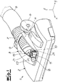
- a vacuum cleaner nozzle according to the invention is shown according to one exemplary embodiment.
- This includes a housing which consists of a housing chassis 2 and a cover 3 is assembled.
- a coupling piece 4 is arranged that is pivotably mounted about a pivot axis running in a transverse direction y.
- Two support rollers 6 are also arranged on the coupling piece 4 .
- the suction connection piece 5 is connected to the housing 1 by means of a corrugated hose 7 .
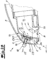
- the air flow inside the housing is shown in the sectional views 2A to 2C. It can be seen there that a suction mouth 8 is arranged on the underside of the housing 1 and is fluidically connected to the suction connection piece 5 via the corrugated hose 7 . Furthermore, a secondary air duct is formed within the housing 1 under the cover 3 . For this purpose, an opening 10 is formed within a suction channel 9 which connects the suction mouth 8 to the suction connection piece 5 . Furthermore, a flap arranged movably within the housing 1 is provided. The flow cross section of the secondary air duct can be adjusted by the distance s between the flap 11 and the opening 10 .
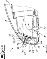
- Figure 2B a half-closed position.
- the distance s between the flap 11 and the opening 10 is reduced here, so that only a reduced secondary air flow 12 can enter the suction channel.
- Figure 2C shows a fully closed position with the gap wide is closed that no or no significant secondary air fractions get into the suction channel 9.
- the suction channel 9 has a collection chamber 13 arranged above the suction mouth 8 and a tubular section 14 running in the longitudinal direction/working direction (x) of the vacuum cleaner nozzle.
- the tubular section 14 simultaneously forms the connection area for the corrugated hose 7 .
- the collection space 13 and the tubular section 14 are connected to one another by a dome 15 .
- the opening 10 is arranged on the dome 15 opposite the tubular section 14 . As indicated by the flow arrows, this results in a particularly low-turbulence confluence of the secondary air flow 12 with the cleaning air flow 16 entering through the suction mouth 8.
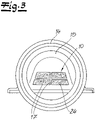
- the suction channel 9 is designed in several parts in the exemplary embodiment.
- the dome 15 and the tubular portion 14 forming component is separately in the 3 shown.
- the figure shows a rear view looking forward in the working direction x. It can be clearly seen that the opening 10 has an overall trapezoidal shape, which is mirror-symmetrical with respect to the longitudinal center plane of the floor nozzle of the vacuum cleaner and is designed with a longer lower edge and an upper edge that is shortened in comparison.
- the opening 10 is also divided into several areas by several webs 17 .
- the flap 11 can be moved by an operating element arranged on the outside of the housing 1 .
- the operating element is in the form of a rotary knob 18 . If one in particular in the Figures 2A to 2C can see, the mobility is provided by a spindle drive.
- the knob 18 is formed with an extension 19 on which an external thread is arranged. The external thread engages in an associated internal thread 20 of the flap 11 . By turning the knob 18, the distance s between the flap 11 and the opening 10 can be adjusted.
- the flap 11 is linearly positively guided on the suction channel 9 by projections 21 in the displacement direction 22 .
- Latching elements 23 at the ends of the projections 21 prevent the flap 11 from falling out of the restraint.
- an elastic plastic molded body 24 is arranged between the flap 11 and the opening 10 .
- This is designed as an open-pored foam body through which air can flow.
- the elastic molded body 24 is bonded over its entire surface to the inside of the flap 11 facing the suction channel 9 . Furthermore, the open-pored foam body 24 finds support in the webs 17 within the opening 10.
Landscapes
- Engineering & Computer Science (AREA)
- Mechanical Engineering (AREA)
- Nozzles For Electric Vacuum Cleaners (AREA)
Description
- Die Erfindung betrifft eine Staubsaugerdüse, insbesondere eine statische Staubsaugerbodendüse mit einem Gehäuse, einem unterseitig an dem Gehäuse angeordneten Saugmund, einem Sauganschlussstutzen zum Anschluss an eine Saugleitung und einem Saugkanal, welcher den Saugmund mit dem Sauganschlussstutzen verbindet. Ferner umfasst die Staubsaugerdüse eine Nebenluftführung.
- Staubsaugerdüsen dienen dazu, den in einem Sauggerät erzeugten Saugluftstrom an einer zu reinigenden Oberfläche, insbesondere Bodenfläche, zu formen und zu kanalisieren. Die Ausgestaltung der Staubsaugerdüse ist dabei für die Reinigungseigenschaften eines Staubsaugers wesentlich. So hängt es maßgeblich von den lokalen Strömungsgeschwindigkeiten eines in eine Staubsaugerdüse eintretenden Saugluftstromes sowie von den anliegenden Druckdifferenzen ab, welche Menge von Schmutzpartikeln von der zu reinigenden Oberfläche gelöst und im Saugluftstrom abtransportiert werden können. Gleichzeitig dient die Staubsaugerdüse auch dazu, den Saugluftstrom auf eine größtmögliche Reinigungsfläche zu verteilen, um so große Oberflächen zügig bearbeiten zu können.
- Zusätzliche Ansprüche an die Gestaltung von Staubsaugerdüsen wurden in der Vergangenheit auch durch Energiesparvorschriften gestellt. So ist aufgrund der EU-Ökodesign-Richtlinien die elektrische Verbrauchsleistung bei Haushaltsstaubsaugern derzeit auf höchstens 900 W beschränkt. Infolgedessen steht auch lediglich eine beschränkte physikalische Saugleistung (Produkt aus Volumenstrom und Druckabfall) zur Verfügung. Um eine gleichbleibende oder verbesserte Reinigungswirkung zu erzielen, müssen Staubsaugerdüsen immer besser an ihren jeweiligen Reinigungszweck angepasst werden. Dies hat zur Folge, dass insbesondere bei der Reinigung von Fußböden immer geringere Spaltmaße zwischen der Unterseite der Staubsaugerdüsen und der zu reinigenden Bodenfläche vorgesehen werden. Hierdurch wird der Saugluftstrom in dem schmalen Spalt stark beschleunigt, so dass dieser Schmutzpartikel besser lösen und mitreißen kann.
- Nachteilig kann hierbei jedoch sein, dass sich aufgrund der geringen Spaltmaße ein hoher Unterdruck im Inneren des Saugkanals einstellt. Infolgedessen wird die Staubsaugerdüse - gerade bei luftundurchlässigen Bodenbelägen - stark an den Fußboden angepresst. Hierdurch ist einerseits eine Beschädigung des Fußbodenbelages möglich und andererseits wird die Handhabung dadurch erheblich gestört, dass zur Bewegung der Staubsaugerdüse höhere Schiebekräfte erforderlich sind. Dieser Effekt wird zusätzlich verstärkt, wenn ein luftundurchlässiges Bodenmaterial eine durchgehende Oberfläche aufweist und nicht mit Fugen oder Profilierungen ausgestattet ist.
- Eine Möglichkeit zur Reduzierung des Schiebewiderstands besteht darin, die Saugleistung zu reduzieren. Hierzu könnte beispielsweise die elektrische Leistung des Gebläses zur Erzeugung des Saugluftstromes gedrosselt oder ein Falschluftventil in der Saugluftführung, üblicherweise an einem Handgriff des Saugrohres vorgesehen werden. Gerade vor dem Hintergrund der ohnehin bereits reduzierten physikalischen Saugleistung kann dies jedoch den Nachteil bringen, dass an der Staubsaugerdüse und in dem daran anschließenden Teil einer Saugluftführung - beispielsweise einem Saugrohr - nicht genügend Saugleistung zur Verfügung steht, um den gelösten Schmutz sicher abzutransportieren. Die Saugleitung weist nämlich gegenüber dem Eintrittsspalt an der Staubsaugerdüse üblicherweise einen stark vergrößerten Strömungsquerschnitt auf. Infolgedessen wird die Strömungsgeschwindigkeit reduziert. Dabei kann es daher vorkommen, dass Schmutzpartikel hoher Dichte - wie beispielsweise Sandkörner oder kleine Steine - nicht ausreichend vom Saugluftstrom beschleunigt werden können, um ihre eigene Gewichtskraft zu überwinden. Die Schmutzpartikel verbleiben infolgedessen im Bereich der Staubsaugerdüse -sofern sie überhaupt vom reduzierten Saugluftstrom von der zu reinigenden Oberfläche gelöst werden können.
- Die Erfindung geht daher von einem Anwendungsszenario aus, bei dem die an der Staubsaugerdüse anliegende Saugleistung nicht reduziert wird und dennoch durch eine Verminderung des Unterdruckes in der Saugdüse die Handhabbarkeit stark verbessert wird. Zu diesem Zweck weist die Staubsaugerdüse eine Nebenluftführung auf. Unter Nebenluft oder Falschluft ist ein Luftstrom zu verstehen, welcher an der Staubsaugerdüse dem Sauganschlussstutzen zugeleitet wird, ohne hierbei den zur Reinigung vorgesehenen Luftweg - insbesondere durch den Saugmund - zu nehmen.
- Zu diesem Zweck sind beispielsweise aus
DE 199 07 580 A1 oderDE 299 23 995 U1 Staubsaugerbodendüsen bekannt, bei denen ein automatisches Nebenluftventil sich bei Unterschreiten eines bestimmten Unterdruckes im Staubsaugerdüseninneren öffnet und so einen Nebenluftstrom ermöglicht. Hierzu ist ein Teil des Saugkanals als elastischer Schlauch ausgebildet. Schlitze in der Schlauchwandung führen dazu, dass diese unabhängig voneinander elastisch verformt und so durch Unterdruckwirkung geöffnet werden können. - Nachteilig hierbei ist jedoch, dass die Öffnungs- und Schließcharakteristik des Nebenluftventils bei der Auslegung der Staubsaugerdüse festgelegt und nicht nachträglich beeinflusst werden kann. Auch einem Verschleiß der elastischen Teile kann der Benutzer nicht wirksam entgegensteuern. Aufgrund der freien Beweglichkeit der Ventilteile ist zusätzlich zu den bei Luftventilen stets auftretenden Geräuschen eine zusätzliche Lärmentwicklung durch Schwingungen und Resonanzen der Ventilteile zu befürchten.
- Aus
EP 2 432 363 A1 offenbart eine Staubsaugerdüse mit einer Nebenluftregelung, welche durch einen eine Ventilplatte betätigenden Griff verwirklicht ist. - Vor diesem Hintergrund liegt der Erfindung die Aufgabe zugrunde, eine Staubsaugerdüse mit einer Schiebekraftreduzierung durch eine Nebenluftführung anzugeben, welche die Nachteile des Standes der Technik überwindet. Insbesondere soll diese leicht und präzise einsetzbar sein und die Geräuschentwicklung minimieren.
- Gegenstand der Erfindung und Lösung dieser Aufgabe ist eine Staubsaugerdüse gemäß Patentanspruch 1. Bevorzugte Ausgestaltungen sind in den Unteransprüchen angegeben.
- Die Erfindung geht von einer gattungsgemäßen Staubsaugerdüse, insbesondere einer statischen Staubsaugerbodendüse mit einem Gehäuse aus. Statische Staubsaugerdüsen verfügen über keine zusätzlichen beweglich angetriebenen Reinigungsmittel wie beispielsweise Borstenwalzen, sondern erzielen die Reinigungswirkung ausschließlich mittels des Saugluftstromes. Das Gehäuse der Staubsaugerdüse kann insbesondere mehrteilig ausgebildet sein und beispielsweise ein Gehäusechassis sowie zumindest einen an dem Gehäuse angeordneten Deckel aufweisen. An dem Gehäuse ist unterseitig ein Saugmund angeordnet. Dieser bezeichnet eine Öffnung, durch welche ein Saugluftstrom bei der Benutzung in das Innere des Gehäuses eintritt. Der Saugmund weist üblicherweise eine längliche, in einer quer zu der Arbeitsrichtung der Staubsaugerdüse verlaufenden Querrichtung langgezogene
- Form auf. Ferner ist ein Sauganschlussstutzen zum Anschluss an eine Saugleitung vorgesehen. Der Sauganschlussstutzen ist üblicherweise um zumindest eine Schwenkachse beweglich mit dem Gehäuse verbunden. Weiterhin umfasst die Staubsaugerdüse einen Saugkanal, welcher den Saugmund mit dem Sauganschlussstutzen verbindet. Hierzu ist der Saugkanal strömungstechnisch direkt oder indirekt mit dem Saugmund und dem Sauganschlussstutzen verbunden. Außerdem weist die Staubsaugerdüse eine Nebenluftführung auf, mittels derer ein Luftstrom unter Umgehung des Saugmundes dem mit der Saugleitung verbindbaren Sauganschlussstutzen zugeführt werden kann.
- Erfindungsgemäß ist die Nebenluftführung mit einer in dem Saugkanal ausgebildeten Öffnung und mit einer innerhalb des Gehäuses beweglich angeordneten Klappe ausgebildet. Der Strömungsquerschnitt der Nebenluftführung ist durch den Abstand zwischen der Klappe und der Öffnung einstellbar. Dabei verbindet die Öffnung das Innere des Saugkanals mit einem Bereich innerhalb des Gehäuses, welcher strömungstechnisch mit der Umgebung verbunden ist. Über den veränderlichen (minimalen) Strömungsquerschnitt der Nebenluftführung lässt sich der Volumenstrom an Nebenluft einstellen. Dabei vergrößert sich der Strömungswiderstand durch die Nebenluftführung je kleiner der Strömungsquerschnitt zwischen der Öffnung in dem Saugkanal und der als separates Teil ausgebildeten Klappe eingestellt ist. Insbesondere kann die Klappe die Öffnung vollständig abdecken, so dass der Nebenluftstrom gänzlich unterbunden wird. Die Klappe ist innerhalb des Gehäuses insbesondere in einem Bereich bewegbar, in dem der minimale Strömungsquerschnitt der Nebenluftführung durch einen Bereich zwischen der Berandung der Öffnung und der Klappe gebildet wird.
- Im Rahmen der Erfindung ist es möglich, den Nebenluftstrom durch den Abstand zwischen der Klappe und der Öffnung situationsentsprechend anzupassen. Hierbei wird durch die Anordnung innerhalb des Gehäuses die Entwicklung von Strömungsgeräuschen bzw. deren Emission reduziert. Weiterhin ist der Verstellmechanismus im Inneren des Gehäuses vor Beschädigungen und Verschmutzungen geschützt.
- In einer besonders bevorzugten Ausgestaltung der Erfindung weist der Saugkanal einen oberhalb des Saugmundes angeordneten Sammelraum sowie ein in Längsrichtung der Staubsaugerdüse (Arbeitsrichtung) verlaufenden rohrförmigen Abschnitt auf. Der Sammelraum und der rohrförmige Abschnitt sind durch einen Dom miteinander verbunden. Dabei ist die Öffnung des Saugkanals an dem Dom gegenüber dem rohrförmigen Abschnitt angeordnet. Durch eine entsprechende Anordnung tritt die Nebenluft in einer Richtung in den Saugkanal ein, welche der späteren Bewegungsrichtung innerhalb des rohrförmigen Abschnittes entspricht. Somit ist keine zusätzliche Umlenkung notwendig, welche zu Verwirblungen mit entsprechenden Störgeräuschen führen könnte. Der Nebenluftstrom nimmt damit einen oberen Bereich des Doms ein, während der reinigende Anteil des Saugluftstromes durch den Saugmund aus Richtung des Sammelraumes von unten hin zutritt. Durch die Zusammenführung mit dem Nebenluftstrom wird dieser abgelenkt, wobei mitgeführte Schmutzpartikel besser abgelenkt werden, ohne an den Deckenbereich des Doms zu stoßen.
- In einer bevorzugten Ausgestaltung der Erfindung ist die Öffnung trapezförmig ausgebildet. Somit lässt sich die Fläche der ebenen Öffnung optimal bei einem zulaufenden oder gerundet ausgeführten Saugkanal - beispielsweise in einem domförmigen Bereich - optimal ausnutzen. Auch wird der größeren Seite der Trapezform verstärkt, was zur gezielten Steuerung eingesetzt werden kann. Besonders bevorzugt ist die Klappe durch ein an der Außenseite der Staubsaugerdüse angeordnetes Bedienelement beweglich. Durch Betätigung des Bedienelementes kann die Klappe zwischen zumindest zwei Positionen bewegt werden, welche einen voneinander verschiedenen minimalen Querschnitt der Nebenluftführung zur Folge haben. Insbesondere kann der Strömungsquerschnitt in einem gewissen Bereich stufenlos eingestellt werden. Durch das von außen zugängliche Bedienelement lässt sich der Strömungsquerschnitt während des Betriebs leicht einstellen und auch bei einem Wechsel des Bodenbelags bedarfsgerecht nachjustieren.
- Besonders bevorzugt ist das Bedienelement als Drehknopf oder Drehknebel ausgebildet. Im Gegensatz zu einem Schiebe- oder Kippschalter lässt sich ein drehendes Bedienelement in einem Winkelbereich von mehr als einer vollständigen Umdrehung einsetzen. Infolgedessen kann hierbei sowohl ein großer Einstellbereich als auch eine hohe Genauigkeit erzielt werden.
- In einer besonders bevorzugten Ausgestaltung ist die Klappe durch einen Spindeltrieb beweglich ausgebildet. Dieser kann unmittelbar an ein drehbares Bedienelement angeschlossen sein. Ein Spindeltrieb lässt sich auf sehr geringem Bauraum umsetzen. Hierbei stellt er eine stufenlose und kraftvolle Verstellmöglichkeit bereit. Überdies ist ein Spindeltrieb bei entsprechender Auslegung selbsthemmend ausgebildet, so dass der Unterdruck innerhalb der Staubsaugerdüse sowie dynamische Belastungen des Nebenluftstroms nicht zu einer Verstellung der Klappe führen.
- In einer besonders bevorzugten Ausgestaltung ist die Klappe an Führungseinrichtungen der Staubsaugerdüse, insbesondere des Saugkanals längs verschieblich geführt. Insbesondere ist die Beweglichkeit der Klappe in Folge der durch die Führungseinrichtung gebildeten Zwangsführung allein auf eine lineare Verschiebbarkeit in einer Richtung reduziert. Hierdurch hat eine Verschiebung der Klappe am gesamten Umfang eine gleichmäßige Änderung des Luftspaltes zur Folge. Die Verschiebungsrichtung steht insbesondere senkrecht zu der Ebene, in welcher die Berandung der Öffnung liegt bzw. in der die Oberfläche der Klappe verläuft. Durch die Zwangsführung wird ein Klappern durch unerwünschte Bewegung der Klappe im Luftstrom verhindert.
- Besonders bevorzugt sind die Führungseinrichtungen als Vorsprünge einstückig an den Saugkanal angeformt. Somit ist automatisch eine korrekte Ausrichtung der Klappe im Verhältnis zu der an dem Saugkanal ausgebildeten Öffnung gewährleistet. Zumindest einer der Vorsprünge kann optional zumindest ein Rastelement aufweisen, mit dem die Klappe innerhalb der Führung gehalten wird.
- In einer alternativen Ausgestaltung kann die Klappe aus verschwenkbar ausgebildet sein.
- Erfindungsgemäß ist zwischen der Klappe und der Öffnung ein elastischer Kunststoffformkörper angeordnet. Der elastische Kunststoffformkörper verhindert Geräusche beim Kontakt zwischen der Klappe und der Berandung der Öffnung und kann überdies - je nach Position der Klappe - auch als Dichtung dienen.
- Der Kunststoffformkörper ist zweckmäßigerweise mit der Klappe verbunden. Insbesondere ist der flächig, ganz besonders vollflächig mit der dem Saugkanal zugewandten Seite der Klappe verklebt. Somit wird eine sichere Positionierung des Kunststoffformkörpers gewährleistet.
- In einer ganz besonders bevorzugten Ausgestaltung der Erfindung ist der Kunststoffformkörper aus offenporigem Schaumstoff gebildet. Je nach Stellung der Klappe wird der Nebenluftstrom dann teilweise oder vollständig durch die Poren des Kunststoffschaums hindurchgeführt. Dies kann zu einer feineren Einstellung des freien Strömungsquerschnitts genutzt werden. Der Nebenluftstrom wird dabei im Porenmaterial verteilt und beruhigt, so dass sich weniger Strömungsgeräusche als an einem durch harte Kanten begrenzten Spalt einstellen.
- Weiterhin ist die Öffnung bevorzugt durch Stege in mehrere Teilöffnungen unterteilt. Die Stege oder Sprossen können dabei zur Abstützung, zur Strömungsberuhigung und/oder ggf. zur Stützung des Formkörpers genutzt werden. Weiterhin dienen sie dem Schutz der Klappe vor in dem Luftstrom durch den Saugmund hereingezogenen Schmutzpartikeln.
- Die Erfindung wird nachfolgend anhand einer lediglich ein Ausführungsbeispiel darstellenden Gestaltung erläutert. Es zeigen dabei schematisch:
- Fig. 1
- eine perspektivische Darstellung einer erfindungsgemäßen Staubsaugerdüse mit einem teilweise aufgebrochenen Gehäuse,
- Fig. 2a bis 2c
- einen Längsschnitt durch die Staubsaugerdüse gemäß
Fig. 1 in verschiedenen Funktionsstellungen und - Fig. 3
- eine rückwertige Detailansicht eines Einzelteils der erfindungsgemäßen Staubsaugerbodendüse.
- In der
Fig. 1 ist eine erfindungsgemäße Staubsaugerdüse gemäß einem Ausführungsbeispiel dargestellt. Diese umfasst ein Gehäuse ein, welches aus einem Gehäusechassis 2 und einem Deckel 3 zusammengesetzt ist. An das Gehäuse 1 ist im rückwertigen Bereich über ein um eine in einer Querrichtung y verlaufende Schwenkachse kippbeweglich gelagertes Koppelstück 4 angeordnet, an dessen hinteren Ende um eine zweite Kippachse schwenkbeweglich gelagert ein Sauganschlussstutzen 5 befestigt ist. An dem Koppelstück 4 sind ferner zwei Stützrollen 6 angeordnet. - Der Sauganschlussstutzen 5 ist mittels eines Wellschlauches 7 mit dem Gehäuse 1 verbunden.
- Die Luftführung im Inneren des Gehäuses ist in den Schnittdarstellungen 2A bis 2C dargestellt. Dort ist erkennbar, dass unterseitig an dem Gehäuse 1 ein Saugmund 8 angeordnet ist, welcher strömungstechnisch über den Wellschlauch 7 mit dem Sauganschlussstutzen 5 verbunden ist. Ferner ist innerhalb des Gehäuses 1 unter dem Deckel 3 eine Nebenluftführung ausgebildet. Dazu ist innerhalb eines Saugkanals 9, welcher den Saugmund 8 mit dem Sauganschlussstutzen 5 verbindet eine Öffnung 10 ausgebildet. Ferner ist eine innerhalb des Gehäuses 1 beweglich angeordnete Klappe vorgesehen. Der Strömungsquerschnitt der Nebenluftführung ist durch den Abstand s zwischen der Klappe 11 und der Öffnung 10 einstellbar.
- In
Fig. 2A ist die maximal geöffnete Position der Klappe 11 dargestellt. Dabei ist der Abstand s maximal groß, so dass sich auch ein maximaler Querschnitt für den Nebenluftstrom 12 ergibt. - Im Unterschied hierzu zeigt die
Fig. 2B eine halb geschlossene Stellung. Der Abstand s zwischen der Klappe 11 und der Öffnung 10 ist hierbei verringert, so dass nur ein verminderter Nebenluftstrom 12 in den Saugkanal eintreten kann.Fig. 2C zeigt eine vollständig geschlossene Position, in der der Spalt soweit zugefahren ist, dass keine bzw. keine wesentlichen Nebenluftanteile in den Saugkanal 9 gelangen. - In der gezeigten Ausführungsform weist der Saugkanal 9 einen oberhalb des Saugmundes 8 angeordneten Sammelraum 13 sowie einen in der Längsrichtung/Arbeitsrichtung (x) der Staubsaugerdüse verlaufenden rohrförmigen Abschnitt 14 auf. Der rohrförmige Abschnitt 14 bildet gleichzeitig den Anschlussbereich für den Wellschlauch 7. Der Sammelraum 13 und der rohrförmige Abschnitt 14 sind durch einen Dom 15 miteinander verbunden. Die Öffnung 10 ist an dem Dom 15 gegenüber dem rohrförmigen Abschnitt 14 angeordnet. Wie durch die Strömungspfeile angedeutet, ergibt sich hierdurch ein besonders turbulentsarmer Zusammenfluss des Nebenluftstromes 12 mit dem durch den Saugmund 8 eintretenden Reinigungsluftstrom 16.
- Der Saugkanal 9 ist im Ausführungsbeispiel mehrteilig ausgebildet. Das den Dom 15 sowie den rohrförmigen Abschnitt 14 bildende Bauteil ist separat in der
Fig. 3 dargestellt. Die Figur zeigt eine Hinteransicht mit Blickrichtung nach vorne in der Arbeitsrichtung x. Es ist deutlich erkennbar, dass die Öffnung 10 insgesamt eine Trapezform aufweist, welche spiegelsymmetrisch bezüglich der Längsmittelebene der Staubsaugerbodendüse ausgebildet und mit einer längeren unteren Kante und einer demgegenüber verkürzten oberen Kante ausgebildet ist. Die Öffnung 10 wird überdies durch mehrere Stege 17 in mehrere Bereiche aufgeteilt. - Die Klappe 11 ist durch ein an der Außenseite des Gehäuses 1 angeordnetes Bedienelement beweglich. Das Bedienelement ist hierbei als Drehknopf 18 ausgebildet. Wenn man insbesondere in den
Figuren 2A bis 2C erkennen kann, wird die Beweglichkeit durch einen Spindeltrieb bereitgestellt. Hierzu ist der Drehknopf 18 mit einem Fortsatz 19 ausgebildet, an dem ein Außengewinde angeordnet ist. Das Außengewinde greift in ein zugeordnetes Innengewinde 20 der Klappe 11 ein. Durch ein Verdrehen des Drehknopfes 18 kann der Abstand s zwischen der Klappe 11 und der Öffnung 10 eingestellt werden. - Die Klappe 11 ist an dem Saugkanal 9 durch Vorsprünge 21 in der Verschiebungsrichtung 22 linear zwangsgeführt. Rastelemente 23 an den Enden der Vorsprünge 21 verhindern ein Herausfallen der Klappe 11 aus der Zwangsführung.
- Im gezeigten Ausführungsbeispiel ist zwischen der Klappe 11 und der Öffnung 10 ein elastischer Kunststoffformkörper 24 angeordnet. Dieser ist als offenporiger Schaumstoffkörper ausgebildet, welcher von Luft durchströmt werden kann. Der elastische Formkörper 24 ist vollflächig mit der dem Saugkanal 9 zugewandten Innenseite der Klappe 11 verklebt. Ferner findet der offenporige Schaumkörper 24 eine Stütze in den Stegen 17 innerhalb der Öffnung 10.
Claims (12)
- Staubsaugerdüse, insbesondere statische Staubsaugerbodendüse, mit einem Gehäuse (1), einem unterseitig an dem Gehäuse (1) angeordneten Saugmund (8), einem Sauganschlussstutzen (5) zum Anschluss an eine Saugleitung, einem Saugkanal (9), welcher den Saugmund (8) mit dem Sauganschlussstutzen (5) verbindet und mit einer Nebenluftführung, wobei die Nebenluftführung eine in dem Saugkanal (9) ausgebildete Öffnung (10) und eine innerhalb des Gehäuses (1) beweglich angeordnete Klappe (11) aufweist und dass der Strömungsquerschnitt der Nebenluftführung durch den Abstand (s) zwischen der Klappe (11) und der Öffnung (10) einstellbar ist, dadurch gekennzeichnet, dass zwischen der Klappe (11) und der Öffnung (10) ein elastischer Kunststoffformkörper (24) angeordnet ist.
- Staubsaugerdüse nach Anspruch 1, dadurch gekennzeichnet, dass der Saugkanal (9) einen oberhalb des Saugmundes (8) angeordneten Sammelraum (13) sowie ein einen in Längsrichtung (x) der Staubsaugerdüse verlaufenden rohrförmigen Abschnitt (14) aufweist, dass der Sammelraum (13) und der rohrförmige Abschnitt (14) durch einen Dom (15) miteinander verbunden sind und dass die Öffnung (10) an dem Dom (15) gegenüber dem rohrförmigen Abschnitt (14) angeordnet ist.
- Staubsaugerdüse nach Anspruch 1 oder 2, dadurch gekennzeichnet, dass die Öffnung (10) trapezförmig ausgebildet ist.
- Staubsaugerdüse nach einem der Ansprüche 1 bis 3, dadurch gekennzeichnet, dass die Klappe (11) durch ein an der Außenseite der Staubsaugerdüse angeordnetes Bedienelement beweglich ist.
- Staubsaugerdüse nach Anspruch 4, dadurch gekennzeichnet, dass das Bedienelement als Drehknopf (18) oder Drehknebel ausgebildet ist.
- Staubsaugerdüse nach einem der Ansprüche 1 bis 5, dadurch gekennzeichnet, dass die Klappe (11) durch einen Spindeltrieb (19, 20) beweglich ist.
- Staubsaugerdüse nach einem der Ansprüche 1 bis 6, dadurch gekennzeichnet, dass die Klappe (11) an Führungseinrichtungen (21) der Staubsaugerdüse, insbesondere des Saugkanals (9), längsverschieblich geführt ist.
- Staubsaugerdüse nach Anspruch 7, dadurch gekennzeichnet, dass die Führungseinrichtungen (21) als Vorsprünge einstückig an den Saugkanal (9) angeformt sind.
- Staubsaugerdüse nach einem der Ansprüche 1 bis 6, dadurch gekennzeichnet, dass die Klappe (11) verschwenkbar ausgebildet ist.
- Staubsaugerdüse nach einem der Ansprüche 1 bis 9, dadurch gekennzeichnet, dass der Kunststoffformkörper (24) mit der Klappe (11) verbunden, insbesondere verklebt ist.
- Staubsaugerdüse nach einem der Ansprüche 1 bis 10, dadurch gekennzeichnet, dass der Kunststoffformkörper (24) aus offenporigem Schaumstoff gebildet ist.
- Staubsaugerdüse nach einem der Ansprüche 1 bis 11, dadurch gekennzeichnet, dass die Öffnung (10) durch Stege (17) in mehrere Teilöffnungen unterteilt ist.
Applications Claiming Priority (1)
| Application Number | Priority Date | Filing Date | Title |
|---|---|---|---|
| DE102018133540.7A DE102018133540A1 (de) | 2018-12-21 | 2018-12-21 | Staubsaugerdüse, insbesondere statische Staubsaugerbodendüse |
Publications (2)
| Publication Number | Publication Date |
|---|---|
| EP3669732A1 EP3669732A1 (de) | 2020-06-24 |
| EP3669732B1 true EP3669732B1 (de) | 2022-10-19 |
Family
ID=67850968
Family Applications (1)
| Application Number | Title | Priority Date | Filing Date |
|---|---|---|---|
| EP19195220.9A Active EP3669732B1 (de) | 2018-12-21 | 2019-09-03 | Staubsaugerdüse, insbesondere statische staubsaugerbodendüse |
Country Status (2)
| Country | Link |
|---|---|
| EP (1) | EP3669732B1 (de) |
| DE (1) | DE102018133540A1 (de) |
Families Citing this family (1)
| Publication number | Priority date | Publication date | Assignee | Title |
|---|---|---|---|---|
| DE102022115600A1 (de) | 2022-06-22 | 2023-12-28 | Wessel-Werk Gmbh | Staubsaugerdüse |
Family Cites Families (9)
| Publication number | Priority date | Publication date | Assignee | Title |
|---|---|---|---|---|
| DE1844732U (de) * | 1961-10-19 | 1962-01-11 | Herbert Schmidt | Mundstueck fuer staubsauger. |
| DE7825557U1 (de) * | 1978-08-28 | 1979-08-23 | Siemens Ag, 1000 Berlin Und 8000 Muenchen | Staubsauger mit einer ueber ein saugrohr angeschlossenen saugduese |
| DE2923193A1 (de) * | 1979-06-08 | 1980-12-11 | Mauz & Pfeiffer Progress | Saugduese fuer einen staubsauger o.dgl. |
| DE29621116U1 (de) * | 1996-12-05 | 1997-02-13 | Wessel-Werk GmbH, 51580 Reichshof | Saugkopf für einen Staubsauger |
| DE19851405C2 (de) * | 1998-11-07 | 2003-04-03 | Wessel Werk Gmbh | Zusatzvorrichtung für statische Staubsaugerdüsen |
| DE29923995U1 (de) | 1999-02-22 | 2001-08-02 | Miele & Cie. GmbH & Co., 33332 Gütersloh | Staubsaugermundstück, wie Bodendüse o.dgl. mit einem Nebenluftventil |
| DE19907580A1 (de) | 1999-02-22 | 2000-08-31 | Miele & Cie | Staubsaugermundstück, wie Bodendüse o. dgl. mit einem Nebenluftventil |
| GB2470406B (en) * | 2009-05-22 | 2012-04-11 | Dyson Technology Ltd | Attachment for vacuum cleaning appliance |
| CN109152503A (zh) * | 2016-01-27 | 2019-01-04 | 中国制造和经纪有限公司 | 用于在地毯表面上操作的具有选择性引入的二次空气流的真空吸尘器动力管嘴 |
-
2018
- 2018-12-21 DE DE102018133540.7A patent/DE102018133540A1/de not_active Ceased
-
2019
- 2019-09-03 EP EP19195220.9A patent/EP3669732B1/de active Active
Also Published As
| Publication number | Publication date |
|---|---|
| EP3669732A1 (de) | 2020-06-24 |
| DE102018133540A1 (de) | 2020-06-25 |
Similar Documents
| Publication | Publication Date | Title |
|---|---|---|
| EP2989953B1 (de) | Verwendung einer an einen bodenstaubsauger anschliessbaren saugdüse zum saugen einer textilen bodenfläche, einer gefliesten hartbodenfläche und einer ungefugten glatten hartbodenfläche | |
| EP2037792B1 (de) | Nebenluftventil | |
| EP2845530B1 (de) | Tragbares Sauggerät für Flüssigkeiten oder Flüssigkeits-/Luftgemische | |
| EP2923623B1 (de) | Staubfilterbeutel für einen staubsauger sowie staubsauger mit einem staubfilterbeutel | |
| EP3669732B1 (de) | Staubsaugerdüse, insbesondere statische staubsaugerbodendüse | |
| EP2918939B1 (de) | Filterpatrone für eine sicherheitswerkbank und sicherheitswerkbank mit mindestens einer filterpatrone | |
| DE20312952U1 (de) | Luftleitvorrichtung, insbesondere für den Innenraum von Fahrzeugen | |
| DE102015108157A1 (de) | Saugdüse für einen Staubsauger | |
| DE10105371A1 (de) | Saugkopf für Haushalts-Bodenstaubsauger | |
| EP4212080B1 (de) | Filterbeutel für einen staubsauger | |
| EP3050475A1 (de) | Saugdüse zum saugen von hartbodenflächen | |
| EP1620611B1 (de) | Festellvorrichtung für eine verfahrbare wand | |
| EP3500145B1 (de) | Bodendüse für einen staubsauger, verfahren zum absaugen von textilflächen und staubsauger | |
| EP3639715B1 (de) | Staubsaugerbodendüse | |
| DE102017118487B4 (de) | Saugdüse für ein ein Sauggebläse aufweisendes Reinigungsgerät | |
| EP2378046B1 (de) | Einrichtung zur Abschottung einer Raumöffnung, insbesondere einer Türöffnung (Türschott) | |
| EP3741276B1 (de) | Staubsauger zur reinigung von bodenflächen | |
| DE202019101089U1 (de) | Vorrichtung zum Absaugen von Luft | |
| EP1714734A1 (de) | Staubabsaugeinrichtung zur lösbaren Anbringung an einem Werkzeuggerät, mit schiebenden Ansaugbereich | |
| EP2123204A2 (de) | Vorrichtung zur Regulierung des Saugluftstroms eines Saugers | |
| DE102005059275B4 (de) | Verblendungsvorrichtung für Fahrzeugdachsysteme mit öffnungsfähigem Deckel | |
| DE10313396A1 (de) | Hochdruckreinigungsgerät für im wesentlichen ebene Flächen | |
| EP2752320B1 (de) | Wasserkasten für ein Kraftfahrzeug | |
| CH674331A5 (en) | Belt type grinding machine - has two endless belts with abrasive surfaces which pass around guide rollers and pressed against workpiece by shoes | |
| EP3763271A1 (de) | Bodendüse für eine saugeinrichtung zur reinigung und pflege von bodenflächen |
Legal Events
| Date | Code | Title | Description |
|---|---|---|---|
| PUAI | Public reference made under article 153(3) epc to a published international application that has entered the european phase |
Free format text: ORIGINAL CODE: 0009012 |
|
| STAA | Information on the status of an ep patent application or granted ep patent |
Free format text: STATUS: REQUEST FOR EXAMINATION WAS MADE |
|
| 17P | Request for examination filed |
Effective date: 20200327 |
|
| AK | Designated contracting states |
Kind code of ref document: A1 Designated state(s): AL AT BE BG CH CY CZ DE DK EE ES FI FR GB GR HR HU IE IS IT LI LT LU LV MC MK MT NL NO PL PT RO RS SE SI SK SM TR |
|
| AX | Request for extension of the european patent |
Extension state: BA ME |
|
| GRAP | Despatch of communication of intention to grant a patent |
Free format text: ORIGINAL CODE: EPIDOSNIGR1 |
|
| STAA | Information on the status of an ep patent application or granted ep patent |
Free format text: STATUS: GRANT OF PATENT IS INTENDED |
|
| RIC1 | Information provided on ipc code assigned before grant |
Ipc: A47L 9/02 20060101AFI20220318BHEP |
|
| GRAS | Grant fee paid |
Free format text: ORIGINAL CODE: EPIDOSNIGR3 |
|
| INTG | Intention to grant announced |
Effective date: 20220412 |
|
| GRAA | (expected) grant |
Free format text: ORIGINAL CODE: 0009210 |
|
| STAA | Information on the status of an ep patent application or granted ep patent |
Free format text: STATUS: THE PATENT HAS BEEN GRANTED |
|
| AK | Designated contracting states |
Kind code of ref document: B1 Designated state(s): AL AT BE BG CH CY CZ DE DK EE ES FI FR GB GR HR HU IE IS IT LI LT LU LV MC MK MT NL NO PL PT RO RS SE SI SK SM TR |
|
| REG | Reference to a national code |
Ref country code: GB Ref legal event code: FG4D Free format text: NOT ENGLISH |
|
| REG | Reference to a national code |
Ref country code: CH Ref legal event code: EP |
|
| REG | Reference to a national code |
Ref country code: IE Ref legal event code: FG4D Free format text: LANGUAGE OF EP DOCUMENT: GERMAN |
|
| REG | Reference to a national code |
Ref country code: DE Ref legal event code: R096 Ref document number: 502019005957 Country of ref document: DE |
|
| REG | Reference to a national code |
Ref country code: AT Ref legal event code: REF Ref document number: 1525037 Country of ref document: AT Kind code of ref document: T Effective date: 20221115 |
|
| REG | Reference to a national code |
Ref country code: LT Ref legal event code: MG9D |
|
| REG | Reference to a national code |
Ref country code: NL Ref legal event code: MP Effective date: 20221019 |
|
| PG25 | Lapsed in a contracting state [announced via postgrant information from national office to epo] |
Ref country code: NL Free format text: LAPSE BECAUSE OF FAILURE TO SUBMIT A TRANSLATION OF THE DESCRIPTION OR TO PAY THE FEE WITHIN THE PRESCRIBED TIME-LIMIT Effective date: 20221019 |
|
| PG25 | Lapsed in a contracting state [announced via postgrant information from national office to epo] |
Ref country code: SE Free format text: LAPSE BECAUSE OF FAILURE TO SUBMIT A TRANSLATION OF THE DESCRIPTION OR TO PAY THE FEE WITHIN THE PRESCRIBED TIME-LIMIT Effective date: 20221019 Ref country code: PT Free format text: LAPSE BECAUSE OF FAILURE TO SUBMIT A TRANSLATION OF THE DESCRIPTION OR TO PAY THE FEE WITHIN THE PRESCRIBED TIME-LIMIT Effective date: 20230220 Ref country code: NO Free format text: LAPSE BECAUSE OF FAILURE TO SUBMIT A TRANSLATION OF THE DESCRIPTION OR TO PAY THE FEE WITHIN THE PRESCRIBED TIME-LIMIT Effective date: 20230119 Ref country code: LT Free format text: LAPSE BECAUSE OF FAILURE TO SUBMIT A TRANSLATION OF THE DESCRIPTION OR TO PAY THE FEE WITHIN THE PRESCRIBED TIME-LIMIT Effective date: 20221019 Ref country code: FI Free format text: LAPSE BECAUSE OF FAILURE TO SUBMIT A TRANSLATION OF THE DESCRIPTION OR TO PAY THE FEE WITHIN THE PRESCRIBED TIME-LIMIT Effective date: 20221019 Ref country code: ES Free format text: LAPSE BECAUSE OF FAILURE TO SUBMIT A TRANSLATION OF THE DESCRIPTION OR TO PAY THE FEE WITHIN THE PRESCRIBED TIME-LIMIT Effective date: 20221019 |
|
| PG25 | Lapsed in a contracting state [announced via postgrant information from national office to epo] |
Ref country code: RS Free format text: LAPSE BECAUSE OF FAILURE TO SUBMIT A TRANSLATION OF THE DESCRIPTION OR TO PAY THE FEE WITHIN THE PRESCRIBED TIME-LIMIT Effective date: 20221019 Ref country code: PL Free format text: LAPSE BECAUSE OF FAILURE TO SUBMIT A TRANSLATION OF THE DESCRIPTION OR TO PAY THE FEE WITHIN THE PRESCRIBED TIME-LIMIT Effective date: 20221019 Ref country code: LV Free format text: LAPSE BECAUSE OF FAILURE TO SUBMIT A TRANSLATION OF THE DESCRIPTION OR TO PAY THE FEE WITHIN THE PRESCRIBED TIME-LIMIT Effective date: 20221019 Ref country code: IS Free format text: LAPSE BECAUSE OF FAILURE TO SUBMIT A TRANSLATION OF THE DESCRIPTION OR TO PAY THE FEE WITHIN THE PRESCRIBED TIME-LIMIT Effective date: 20230219 Ref country code: HR Free format text: LAPSE BECAUSE OF FAILURE TO SUBMIT A TRANSLATION OF THE DESCRIPTION OR TO PAY THE FEE WITHIN THE PRESCRIBED TIME-LIMIT Effective date: 20221019 Ref country code: GR Free format text: LAPSE BECAUSE OF FAILURE TO SUBMIT A TRANSLATION OF THE DESCRIPTION OR TO PAY THE FEE WITHIN THE PRESCRIBED TIME-LIMIT Effective date: 20230120 |
|
| REG | Reference to a national code |
Ref country code: DE Ref legal event code: R097 Ref document number: 502019005957 Country of ref document: DE |
|
| PG25 | Lapsed in a contracting state [announced via postgrant information from national office to epo] |
Ref country code: SM Free format text: LAPSE BECAUSE OF FAILURE TO SUBMIT A TRANSLATION OF THE DESCRIPTION OR TO PAY THE FEE WITHIN THE PRESCRIBED TIME-LIMIT Effective date: 20221019 Ref country code: RO Free format text: LAPSE BECAUSE OF FAILURE TO SUBMIT A TRANSLATION OF THE DESCRIPTION OR TO PAY THE FEE WITHIN THE PRESCRIBED TIME-LIMIT Effective date: 20221019 Ref country code: EE Free format text: LAPSE BECAUSE OF FAILURE TO SUBMIT A TRANSLATION OF THE DESCRIPTION OR TO PAY THE FEE WITHIN THE PRESCRIBED TIME-LIMIT Effective date: 20221019 Ref country code: DK Free format text: LAPSE BECAUSE OF FAILURE TO SUBMIT A TRANSLATION OF THE DESCRIPTION OR TO PAY THE FEE WITHIN THE PRESCRIBED TIME-LIMIT Effective date: 20221019 Ref country code: CZ Free format text: LAPSE BECAUSE OF FAILURE TO SUBMIT A TRANSLATION OF THE DESCRIPTION OR TO PAY THE FEE WITHIN THE PRESCRIBED TIME-LIMIT Effective date: 20221019 |
|
| PLBE | No opposition filed within time limit |
Free format text: ORIGINAL CODE: 0009261 |
|
| STAA | Information on the status of an ep patent application or granted ep patent |
Free format text: STATUS: NO OPPOSITION FILED WITHIN TIME LIMIT |
|
| PG25 | Lapsed in a contracting state [announced via postgrant information from national office to epo] |
Ref country code: SK Free format text: LAPSE BECAUSE OF FAILURE TO SUBMIT A TRANSLATION OF THE DESCRIPTION OR TO PAY THE FEE WITHIN THE PRESCRIBED TIME-LIMIT Effective date: 20221019 Ref country code: AL Free format text: LAPSE BECAUSE OF FAILURE TO SUBMIT A TRANSLATION OF THE DESCRIPTION OR TO PAY THE FEE WITHIN THE PRESCRIBED TIME-LIMIT Effective date: 20221019 |
|
| 26N | No opposition filed |
Effective date: 20230720 |
|
| PG25 | Lapsed in a contracting state [announced via postgrant information from national office to epo] |
Ref country code: SI Free format text: LAPSE BECAUSE OF FAILURE TO SUBMIT A TRANSLATION OF THE DESCRIPTION OR TO PAY THE FEE WITHIN THE PRESCRIBED TIME-LIMIT Effective date: 20221019 |
|
| REG | Reference to a national code |
Ref country code: CH Ref legal event code: PL |
|
| PG25 | Lapsed in a contracting state [announced via postgrant information from national office to epo] |
Ref country code: LU Free format text: LAPSE BECAUSE OF NON-PAYMENT OF DUE FEES Effective date: 20230903 |
|
| REG | Reference to a national code |
Ref country code: BE Ref legal event code: MM Effective date: 20230930 |
|
| GBPC | Gb: european patent ceased through non-payment of renewal fee |
Effective date: 20230903 |
|
| PG25 | Lapsed in a contracting state [announced via postgrant information from national office to epo] |
Ref country code: LU Free format text: LAPSE BECAUSE OF NON-PAYMENT OF DUE FEES Effective date: 20230903 Ref country code: MC Free format text: LAPSE BECAUSE OF FAILURE TO SUBMIT A TRANSLATION OF THE DESCRIPTION OR TO PAY THE FEE WITHIN THE PRESCRIBED TIME-LIMIT Effective date: 20221019 |
|
| REG | Reference to a national code |
Ref country code: IE Ref legal event code: MM4A |
|
| PG25 | Lapsed in a contracting state [announced via postgrant information from national office to epo] |
Ref country code: IE Free format text: LAPSE BECAUSE OF NON-PAYMENT OF DUE FEES Effective date: 20230903 |
|
| PG25 | Lapsed in a contracting state [announced via postgrant information from national office to epo] |
Ref country code: GB Free format text: LAPSE BECAUSE OF NON-PAYMENT OF DUE FEES Effective date: 20230903 |
|
| PG25 | Lapsed in a contracting state [announced via postgrant information from national office to epo] |
Ref country code: CH Free format text: LAPSE BECAUSE OF NON-PAYMENT OF DUE FEES Effective date: 20230930 |
|
| PG25 | Lapsed in a contracting state [announced via postgrant information from national office to epo] |
Ref country code: IE Free format text: LAPSE BECAUSE OF NON-PAYMENT OF DUE FEES Effective date: 20230903 Ref country code: GB Free format text: LAPSE BECAUSE OF NON-PAYMENT OF DUE FEES Effective date: 20230903 Ref country code: CH Free format text: LAPSE BECAUSE OF NON-PAYMENT OF DUE FEES Effective date: 20230930 |
|
| PG25 | Lapsed in a contracting state [announced via postgrant information from national office to epo] |
Ref country code: BE Free format text: LAPSE BECAUSE OF NON-PAYMENT OF DUE FEES Effective date: 20230930 |
|
| PGFP | Annual fee paid to national office [announced via postgrant information from national office to epo] |
Ref country code: IT Payment date: 20240924 Year of fee payment: 6 |
|
| PG25 | Lapsed in a contracting state [announced via postgrant information from national office to epo] |
Ref country code: BG Free format text: LAPSE BECAUSE OF FAILURE TO SUBMIT A TRANSLATION OF THE DESCRIPTION OR TO PAY THE FEE WITHIN THE PRESCRIBED TIME-LIMIT Effective date: 20221019 |
|
| PG25 | Lapsed in a contracting state [announced via postgrant information from national office to epo] |
Ref country code: BG Free format text: LAPSE BECAUSE OF FAILURE TO SUBMIT A TRANSLATION OF THE DESCRIPTION OR TO PAY THE FEE WITHIN THE PRESCRIBED TIME-LIMIT Effective date: 20221019 |
|
| PG25 | Lapsed in a contracting state [announced via postgrant information from national office to epo] |
Ref country code: CY Free format text: LAPSE BECAUSE OF FAILURE TO SUBMIT A TRANSLATION OF THE DESCRIPTION OR TO PAY THE FEE WITHIN THE PRESCRIBED TIME-LIMIT; INVALID AB INITIO Effective date: 20190903 |
|
| PG25 | Lapsed in a contracting state [announced via postgrant information from national office to epo] |
Ref country code: HU Free format text: LAPSE BECAUSE OF FAILURE TO SUBMIT A TRANSLATION OF THE DESCRIPTION OR TO PAY THE FEE WITHIN THE PRESCRIBED TIME-LIMIT; INVALID AB INITIO Effective date: 20190903 |
|
| PGFP | Annual fee paid to national office [announced via postgrant information from national office to epo] |
Ref country code: DE Payment date: 20250910 Year of fee payment: 7 |
|
| PGFP | Annual fee paid to national office [announced via postgrant information from national office to epo] |
Ref country code: FR Payment date: 20250922 Year of fee payment: 7 |
|
| REG | Reference to a national code |
Ref country code: AT Ref legal event code: MM01 Ref document number: 1525037 Country of ref document: AT Kind code of ref document: T Effective date: 20240903 |
|
| PG25 | Lapsed in a contracting state [announced via postgrant information from national office to epo] |
Ref country code: TR Free format text: LAPSE BECAUSE OF FAILURE TO SUBMIT A TRANSLATION OF THE DESCRIPTION OR TO PAY THE FEE WITHIN THE PRESCRIBED TIME-LIMIT Effective date: 20221019 |
|
| PG25 | Lapsed in a contracting state [announced via postgrant information from national office to epo] |
Ref country code: AT Free format text: LAPSE BECAUSE OF NON-PAYMENT OF DUE FEES Effective date: 20240903 |