EP3669428B1 - Miteinander verriegelbare steckverbindermodule - Google Patents
Miteinander verriegelbare steckverbindermodule Download PDFInfo
- Publication number
- EP3669428B1 EP3669428B1 EP18759546.7A EP18759546A EP3669428B1 EP 3669428 B1 EP3669428 B1 EP 3669428B1 EP 18759546 A EP18759546 A EP 18759546A EP 3669428 B1 EP3669428 B1 EP 3669428B1
- Authority
- EP
- European Patent Office
- Prior art keywords
- connector module
- connector
- camshaft
- pin
- button
- Prior art date
- Legal status (The legal status is an assumption and is not a legal conclusion. Google has not performed a legal analysis and makes no representation as to the accuracy of the status listed.)
- Active
Links
Images
Classifications
-
- H—ELECTRICITY
- H01—ELECTRIC ELEMENTS
- H01R—ELECTRICALLY-CONDUCTIVE CONNECTIONS; STRUCTURAL ASSOCIATIONS OF A PLURALITY OF MUTUALLY-INSULATED ELECTRICAL CONNECTING ELEMENTS; COUPLING DEVICES; CURRENT COLLECTORS
- H01R13/00—Details of coupling devices of the kinds covered by groups H01R12/70 or H01R24/00 - H01R33/00
- H01R13/62—Means for facilitating engagement or disengagement of coupling parts or for holding them in engagement
- H01R13/639—Additional means for holding or locking coupling parts together, after engagement, e.g. separate keylock, retainer strap
-
- H—ELECTRICITY
- H01—ELECTRIC ELEMENTS
- H01R—ELECTRICALLY-CONDUCTIVE CONNECTIONS; STRUCTURAL ASSOCIATIONS OF A PLURALITY OF MUTUALLY-INSULATED ELECTRICAL CONNECTING ELEMENTS; COUPLING DEVICES; CURRENT COLLECTORS
- H01R13/00—Details of coupling devices of the kinds covered by groups H01R12/70 or H01R24/00 - H01R33/00
- H01R13/62—Means for facilitating engagement or disengagement of coupling parts or for holding them in engagement
- H01R13/627—Snap or like fastening
- H01R13/6276—Snap or like fastening comprising one or more balls engaging in a hole or a groove
-
- H—ELECTRICITY
- H01—ELECTRIC ELEMENTS
- H01R—ELECTRICALLY-CONDUCTIVE CONNECTIONS; STRUCTURAL ASSOCIATIONS OF A PLURALITY OF MUTUALLY-INSULATED ELECTRICAL CONNECTING ELEMENTS; COUPLING DEVICES; CURRENT COLLECTORS
- H01R13/00—Details of coupling devices of the kinds covered by groups H01R12/70 or H01R24/00 - H01R33/00
- H01R13/66—Structural association with built-in electrical component
- H01R13/70—Structural association with built-in electrical component with built-in switch
-
- H—ELECTRICITY
- H01—ELECTRIC ELEMENTS
- H01R—ELECTRICALLY-CONDUCTIVE CONNECTIONS; STRUCTURAL ASSOCIATIONS OF A PLURALITY OF MUTUALLY-INSULATED ELECTRICAL CONNECTING ELEMENTS; COUPLING DEVICES; CURRENT COLLECTORS
- H01R27/00—Coupling parts adapted for co-operation with two or more dissimilar counterparts
- H01R27/02—Coupling parts adapted for co-operation with two or more dissimilar counterparts for simultaneous co-operation with two or more dissimilar counterparts
Definitions
- the invention is based on a system consisting of two plug-in connector modules that can be reversibly locked to one another, according to the preamble of independent claim 1.
- Such connector modules are typically used in modular industrial connectors.
- the industrial connectors can be fitted with different connector modules, which means that such connectors can be used in a particularly diverse manner in the industrial environment.
- the connector modules are used in so-called holding frames, which in turn are screwed into industrial connector housings.
- the DE 10 2013 113 976 B4 shows such a holding frame for a heavy connector for accommodating similar and/or different connector modules.
- the holding frame consists of a base body which has two opposite side parts. A cheek piece made of a flexible material is attached to each of the side pieces. When inserting a connector module into the holding frame, these cheek parts are bent outwards away from the side part, as a result of which the connector modules are fixed in one plane within the base body.
- a mechanical lock is required to ensure a secure connection between a connector and a mating connector. This protects the plug connection from unintentional opening.
- industrial connectors are locked together using locking brackets attached to the outside of the housing.
- Locking devices attached to the outside of the connector housing can easily be damaged, for example if a connector falls. Therefore, connectors with a locking device arranged within the housing are also known.
- the WO 9 015 282 A1 shows an axial locking device in which two separable elements can be locked and unlocked with one another by relative movement. Locking and unlocking is done by a cam slide that can rotate and move axially.
- the cam follower has flexible teeth that can engage reaction teeth and undulatory teeth that can engage complementary teeth.
- the DE 10 2009 039 652 A1 shows a device for locking a plug in a socket, which is arranged integrated in a charging station or in a vehicle that can be operated using electrical energy, with a movably mounted latching element which, when it is in a latched position, engages in a recess of the plug to connect it to the socket .
- the US 20 040 002 249 A1 shows a circuit board connector with multiple contact pads that are electrically connected to multiple signal lines on one side.
- the connector has a shaft, which is provided near the central part of the circuit board and perpendicular to the circuit board, and serves to lock the circuit board connector on the circuit board.
- the U.S. 6,786,753 B1 shows a device base comprising a base, an elliptical rotational foundation which is arranged in the base, two balls inserted into recesses of a Connector can be pressed and clamped, whereby a connector is fixed in the device base.
- EP1102363A1 discloses a locking means in a connector module which is held in a holding frame of a connector. This locking means locks with a mating connector.
- the DE 10 2008 060 561 B4 shows, for example, a connector with an internal locking device.
- a spring plate is arranged on the inside of a plug, which is provided for latching with a locking lug arranged on the inside of a mating plug.
- a push button is arranged on the outside of the plug, which protrudes through the wall of the plug and acts on the spring plate in such a way that the locking to the locking lug can be released.
- Such locking devices often have a very complex mechanical design and can therefore only be produced at high cost.
- mechanical solutions cannot be controlled electronically.
- German Patent and Trademark Office has researched the following prior art in the priority application for the present application: DE 10 2009 039 652 A1 , DE 32 20 839 C2 , DE 10 2011 004 648 A1 , DE 10 2016 105 975 A1 .
- the object of the invention is to propose a system of connector modules that can be reversibly locked to one another, which is simple in design, mechanically stable and at the same time inexpensive.
- the system according to the invention consists of a first connector module and a second connector module.
- the connector modules are usually integrated into an industrial connector and arranged opposite one another.
- the industrial connectors and thus the connector modules can be plugged into one another.
- one connector module engages in the other connector module.
- the first connector module has a locking means, as a result of which the connector modules can be locked to one another in a reversible manner.
- the connectors containing the connector modules are also locked together.
- the connector modules thus represent the above-mentioned locking device for the industrial connectors.
- the connector modules are protected within the housing of the respective industrial connector.
- the locking means is a camshaft.
- a camshaft is a machine element in the form of a rod on which at least one rounded projection, a so-called “cam” is attached.
- the rod rotates on its own axis, causing the cams mounted on it to perform a longitudinal movement (perpendicular to the extension of the rod).
- the axis of rotation of the camshaft is advantageously aligned parallel to the insertion direction of the first connector module. In this way, the camshaft can be integrated into the connector module to save space.
- the first connector module preferably has an electric motor, with which the camshaft can be brought into a rotational movement.
- the electric motor can be supplied with current, for example via conductors connected to the connector module.
- a power supply via a battery integrated in the connector module is also conceivable.
- the first connector module has a pin that protrudes in the direction of insertion.
- the camshaft runs at least partially in this journal. This means that the camshaft protrudes at least partially into the protruding journal.
- the pin is designed here as a cuboid extension that can be plugged into a receptacle of a mating connector module provided for this purpose.
- the second connector module has a receptacle. When plugged in, the pin and thus also the camshaft located therein of the first connector module penetrate into the receptacle of the second connector module.
- the pin of the first connector module preferably has at least one hole at the end.
- the hole runs transversely to the extension direction of the pin.
- a ball is placed in the hole.
- the balls are preferably made of steel or a hard plastic and are used to lock the first connector module to the second connector module. The exact way it works is explained in more detail below.
- the housing of the second connector module has at least one hole that corresponds to the hole in the pin of the first connector module.
- the receptacle preferably also has two holes which, in the plugged-in state, each face a hole in the pin.
- the camshaft of the first connector module is in operative contact with the balls located in the pin and arranged in its holes.
- the respective ball can be pushed at least partially into the hole located in the receptacle of the second connector module by a rotational movement of the camshaft, as a result of which the first connector module and the second connector module can be locked together.
- the camshaft has a substantially oval or elliptical cross section in the area of the journal.
- This oval shape can be understood as the "cam" of the camshaft already mentioned above, with which the balls can be displaced transversely to the plug-in direction. If the diameter of the camshaft widens in the cross-sectional plane of the journal, the balls are at least partially driven out of the holes in the journal of the first connector module into the holes in the recesses of the second connector module. Pulling apart the two connector modules is now blocked by the balls. The connector modules are locked together. If the diameter of the camshaft decreases in the cross-sectional plane of the journal, the balls can move back in move in the holes of the peg, which will unlock the connector modules. The connector modules can thus be transferred from a locked to an unlocked state.
- the camshaft is connected to the electric motor.
- the camshaft has a substantially oval or elliptical cross-section, which can be considered a "cam".
- This oval area is perpendicular to the oval area in the trunnion. This means that if the camshaft has a large diameter in the area of the journal within the cross-sectional plane of the connector module, the diameter of the camshaft in the area of the electric motor becomes small and vice versa.
- the camshaft can be viewed here as a rod with a total of two cams, a first cam in the area of the electric motor and a second cam in the area of the pin. Both cams are perpendicular to each other.
- the first connector module has at least two buttons, a first button and a second button.
- the first button is arranged in the area of the electric motor.
- the first button is touched or activated by the camshaft when the first connector module and the second connector module are not locked together.
- the first cam of the camshaft is guided against a switch on the first button, thereby activating it.
- the second button is arranged away from the electric motor in the direction of the pin of the first connector module.
- the second button is from touches a cam of the camshaft when the first connector module and the second connector module are locked together. In this case, the second cam of the camshaft is guided against a switch on the second button, thereby activating it.
- the connector modules each have an interface.
- the connector modules can exchange signals and/or data via the interface when they are plugged into one another. Among other things, this can involve control signals that activate the electric motor and thus initiate locking and/or unlocking of the connector modules.
- the interfaces can be designed, for example, as plug connectors and associated sockets.
- the first connector module and/or the second connector module preferably has an interface.
- This interface can be contact pins, for example, which can be brought into electrical contact with a holding frame in which the connector modules are located.
- the holding frame can have data lines and ensure a connection of the connector modules via a suitable data bus. This can be used to transmit operating states of a machine to the connector modules, for example, which initiate or trigger locking and/or unlocking of the connector modules according to the invention.
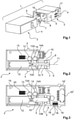
- the figure 1 shows a perspective view of a system 1 consisting of a first connector module 2 and a second connector module 3.
- the connector modules 2, 3 have an essentially cuboid basic shape.
- the connector modules 2, 3 each have retaining pins 4 on their narrow sides, with which they can be fixed in a retaining frame (not shown) of an industrial connector (not shown).
- the fixing process of the connector modules 2, 3 in a holding frame is adequately described.
- the first connector module 2 has a pin 5 protruding in the direction of insertion.
- the pin 5 is essentially cuboid.
- holes 6 are introduced or formed, in each of which a ball 7 is arranged.
- the pin 5 is guided into a receptacle 8 provided for this purpose in the second connector module 3 .
- holes 9 are introduced or formed.
- a camshaft 10 is arranged in the first connector module 2 .
- the axis of rotation 11 of the camshaft runs parallel to the plug-in direction of the first connector module 1.
- the camshaft 10 extends to a large extent within the journal 5.
- the camshaft 10 is connected to an electric motor 12, with which the camshaft 10 can be brought into a rotational movement.
- the camshaft 10 has two cams, a first cam 10A and a second cam 10B.
- the cams 10A, 10B are essentially extensions of the rod-shaped basic shape of the camshaft 10.
- the cams 10A, 10B are perpendicular to one another in cross section.
- the second cam 10B extends for the most part in the pin 5 of the first connector module 2.
- buttons 13, 14 are arranged in the first connector module 2.
- the buttons 13, 14 each have a switch 13A, 14A, via which the respective buttons 13, 14 can be activated.
- the first button 13 is located at the interface between the electric motor 12 and the camshaft 10 at the level of the first cam 10A.
- the second button 14 is located away from it in the insertion direction at the level of the second cam 10B of the camshaft 10.
- the cams 10A, 10B of the camshaft 10 are perpendicular to one another in cross section. If the first button 13 is activated via the first cam 10A, the balls 7 are not pushed out of the holes 7 of the pin 5 into the holes 9 of the receptacle 8 by the second cam 10B. The connector modules 2, 3 are then in an unlocked state and can be pulled apart. If the second button 14 is activated via the second cam 10B, the balls 7 have been pushed out of the holes 7 of the pin 5 into the holes 9 of the receptacle 8 by the second cam 10B. The connector modules 2, 3 are now in a locked condition and cannot be pulled apart. The aforementioned locking states can be monitored and also initiated via a microprocessor 20 . The microprocessor 20 can control the electric motor 12 accordingly. About the button 13, 14, the locking states can be detected.
- the first connector module 2 has a plug-in extension 15 arranged next to the pin 5 .
- Contact elements are arranged in the plug extension.
- the second plug-in connector module 3 has a socket 16 into which the plug-in extension 15 can be inserted during the plug-in process.
- the plug-in extension 15 and the socket 16 each form an interface via which the connector modules 2, 3 can exchange signals and/or data.
- the second connector module 3 has an interface 17 on a narrow side, which can be connected to a holding frame (not shown).
- the interface 17 has three contact pins 18 .
- the second connector module 3 can communicate with other connector modules located in the holding frame via the interface 17 and/or receive signals and/or data from another location or forward them there. For example, the above-mentioned locking states can be communicated via this interface 17 and/or a command to lock or unlock is received.
- Both connector modules 2, 3 have a printed circuit board 19, 19' and other electronic components, such as microprocessors 20, 20'.
- the connector modules 2, 3 can act autonomously via these components according to programming and/or be controlled from the outside and execute commands.
Landscapes
- Details Of Connecting Devices For Male And Female Coupling (AREA)
Description
- Die Erfindung geht aus von einem System bestehend aus zwei miteinander reversibel verriegelbarer Steckverbindermodule nach der Gattung des unabhängigen Anspruchs 1.
- Derartige Steckverbindermodule werden in der Regel in modularen Industriesteckverbindern eingesetzt. Die Industriesteckverbinder können mit unterschiedlichen Steckverbindermodulen bestückt werden, wodurch derartige Steckverbinder im industriellen Umfeld besonders vielfältig eingesetzt werden können.
- Die Steckverbindermodule werden in so genannten Halterahmen eingesetzt, die wiederum in Industriesteckverbindergehäusen eingeschraubt werden. Die
DE 10 2013 113 976 B4 zeigt einen solchen Halterahmen für einen schweren Steckverbinder zur Aufnahme gleichartiger und/oder unterschiedlicher Steckverbindermodule. Der Halterahmen besteht aus einem Grundkörper, der zwei sich gegenüberliegenden Seitenteile aufweist. An den Seitenteilen ist jeweils ein Wangenteil, bestehend aus einem flexiblen Material, angebracht. Beim Einführen eines Steckverbindermoduls in den Halterahmen werden diese Wangenteile vom Seitenteil weg nach außen gebogen, wodurch die Steckverbindermodule innerhalb des Grundkörpers in einer Ebene fixiert werden. - Um eine sichere Verbindung von einem Steckverbinder und einem Gegensteckverbinder zu gewährleisten, wird eine mechanische Verriegelung benötigt. Dadurch wird die Steckverbindung vor ungewolltem Öffnen geschützt. In der Regel werden Industriesteckverbinder mithilfe von außen am Gehäuse angebrachten Verriegelungsbügeln miteinander verriegelt.
- Außen am Gehäuse der Steckverbinder angebrachte Verriegelungsvorrichtungen können leicht, beispielsweise beim Herabfallen eines Steckverbinders, beschädigt werden. Daher sind auch Steckverbinder mit einer innerhalb des Gehäuses angeordneten Verriegelungsvorrichtung bekannt.
- Die
WO 9 015 282 A1 - Die
DE 10 2009 039 652 A1 zeigt eine Vorrichtung zur Verriegelung eines Steckers in einer Steckdose, die in einer Ladesäule oder in einem mittels elektrischer Energie betreibbaren Fahrzeug integriert angeordnet ist, mit einem beweglich gelagerten Rastelement, das in einer Raststellung desselben in eine Ausnehmung des Steckers eingreift zur Verbindung desselben mit der Steckdose. - Die
US 20 040 002 249 A1 zeigt einen Platinensteckverbinder mit mehreren Kontaktflächen, die auf einer Seite elektrisch mit mehreren Signalleitungen verbunden sind. Der Verbinder hat eine Welle, die nahe dem zentralen Teil der Platine und senkrecht zur Platine vorgesehen ist und zur Verriegelung des Platinensteckverbinders auf der Platine dient. - Die
US 6 786 753 B1 zeigt einen Gerätesockel umfassend einen Sockel, ein ellipsenförmiges Rotationsfundament welches in dem Sockel angeordnet ist, zwei Kugeln, die in Ausnehmungen eines eingeführten Steckers drückbar und eingeklemmbar sind, wodurch ein Stecker im Gerätesockel fixiert ist. -
EP1102363A1 offenbart ein Verriegelungsmittel in einem Verbindermodul, das in einem Halterahmen eines Verbinders gehalten wird. Dieses Verriegelungsmittel verriegelt mit einem Gegensteckverbinder. - Die
DE 10 2008 060 561 B4 zeigt beispielsweise einen Steckverbinder mit einer innenliegenden Verriegelungsvorrichtung. Dabei ist auf der Innenseite eines Steckers ein Federblech angeordnet, welches zur Verrastung mit einem auf der Innenseite eines Gegensteckers angeordneten Rastnase vorgesehen ist. Auf der Außenseite des Steckers ist ein Druckknopf angeordnet, welcher durch die Wand des Steckers ragt und auf das Federblech so einwirkt, dass die Verrastung zur Rastnase gelöst werden kann. - Derartige Verriegelungsvorrichtungen sind oft mechanisch sehr komplex aufgebaut und daher nur kostenintensiv herstellbar. Außerdem können derartige mechanische Lösung nicht elektronisch gesteuert werden.
- Das Deutsche Patent- und Markenamt hat in der Prioritätsanmeldung zu vorliegender Anmeldung den folgenden Stand der Technik recherchiert:
DE 10 2009 039 652 A1 ,DE 32 20 839 C2 ,DE 10 2011 004 648 A1 ,DE 10 2016 105 975 A1 . - Ferner wurde vom Deutschen Patent- und Markenamt auch die folgende Nicht-Patentliteratur recherchiert:
KRAUSE, Werner: Konstruktionselemente der Feinmechanik. Bd. 1, 3., aktualisierte Auflage. München: Hanser 2004. Seite 448-449. - Die Aufgabe der Erfindung besteht darin ein System aus miteinander reversibel verriegelbarer Steckverbindermodule vorzuschlagen, welches einfach aufgebaut, mechanisch stabil und gleichzeitig kostengünstig ausgeführt ist.
- Die Aufgabe wird durch die kennzeichnenden Merkmale des Gegenstands des Anspruchs 1 gelöst.
- Vorteilhafte Ausgestaltungen der Erfindung sind in den Unteransprüchen angegeben.
- Das erfindungsgemäße System besteht aus einem ersten Steckverbindermodul und einem zweiten Steckverbindermodul. Die Steckverbindermodule sind in der Regel jeweils in einem Industriesteckverbinder integriert und gegenüberstehend angeordnet. Die Industriesteckverbinder und damit die Steckverbindermodule können miteinander gesteckt werden. Dabei greift das eine Steckverbindermodul in das jeweils andere Steckverbindermodul ein. Das erste Steckverbindermodul weist ein Verriegelungsmittel auf, wodurch die Steckverbindermodule reversibel miteinander verriegelbar sind.
- Durch die Verriegelung der Steckverbindermodule werden auch die die Steckverbindermodule enthaltenen Steckverbinder miteinander verriegelt. Die Steckverbindermodule stellen damit die oben erwähnte Verriegelungsvorrichtung für die Industriesteckverbinder dar. Die Steckverbindermodule sind innerhalb des Gehäuses des jeweiligen Industriesteckverbinders geschützt.
- In einer vorteilhaften Ausgestaltung der Erfindung handelt es sich beim Verriegelungsmittel um eine Nockenwelle. Eine Nockenwelle ist ein Maschinenelement in Form eines Stabes, auf dem mindestens ein gerundeter Vorsprung, eine so genannte "Nocke" angebracht ist. Der Stab dreht sich um die eigene Achse, wodurch die auf ihm angebrachten Nocken eine Längsbewegung (senkrecht zur Ausdehnung des Stabes) durchführen.
- Vorteilhafterweise ist die Drehachse der Nockenwelle parallel zur Steckrichtung des ersten Steckverbindermoduls ausgerichtet. So kann die Nockenwelle platzsparend im Steckverbindermodul integriert werden.
- Vorzugsweise weist das erste Steckverbindermodul einen Elektromotor auf, mit welchem die Nockenwelle in eine Rotationsbewegung bringbar ist. Der Elektromotor kann beispielsweise über am Steckverbindermodul angeschlossene Leiter mit Strom versorgt werden. Eine Stromversorgung über eine im Steckverbindermodul integrierte Batterie ist ebenfalls denkbar.
- In einer besonders vorteilhaften Variante der Erfindung weist das erste Steckverbindermodul einen in Steckrichtung hervorstehenden Zapfen auf. In diesem Zapfen verläuft die Nockenwelle zumindest teilweise. Das bedeutet, dass die Nockenwelle zumindest teilweise in den hervorstehenden Zapfen hineinragt. Der Zapfen ist hier als quaderförmiger Fortsatz ausgeführt, der in eine dafür vorgesehene Aufnahme eines Gegensteckverbindermoduls gesteckt werden kann. Das zweite Steckverbindermodul weist eine Aufnahme auf. Im gesteckten Zustand dringt der Zapfen und damit auch die darin befindliche Nockenwelle des ersten Steckverbindermoduls in die Aufnahme des zweiten Steckverbindermoduls ein.
- Vorzugsweise weist der Zapfen des ersten Steckverbindermoduls endseitig zumindest ein Loch auf. Das Loch verläuft quer zur Erstreckungsrichtung des Zapfens. In dem Loch ist eine Kugel angeordnet. Idealerweise sind zwei entsprechende Löcher im Zapfen vorhanden, die gegenüberstehend angeordnet sind und in denen jeweils eine Kugel angeordnet ist. Die Kugeln sind vorzugsweise aus Stahl oder einem harten Kunststoff gefertigt und dienen zur Verriegelung des ersten Steckverbindermoduls mit dem zweiten Steckverbindermodul. Die genaue Funktionsweise wird im Folgenden näher erläutert.
- Vorteilhafterweise weist die Aufnahme des zweiten Steckverbindermoduls zumindest ein Loch auf, das zu dem Loch des Zapfens des ersten Steckverbindermoduls korrespondiert. Vorzugsweise weist auch die Aufnahme zwei Löcher auf, die im gesteckten Zustand jeweils einem Loch des Zapfens gegenüberstehen.
- Die Nockenwelle des ersten Steckverbindermoduls steht in Wirkkontakt mit den im Zapfen befindlichen und in dessen Löchern angeordneten Kugeln. Die jeweilige Kugel ist durch eine Rotationsbewegung der Nockenwelle zumindest teilweise in das in der Aufnahme des zweiten Steckverbindermoduls befindliche Loch hineinschiebbar, wodurch das erste Steckverbindermodul und das zweite Steckverbindermodul miteinander verriegelbar sind.
- Die Nockenwelle weist im Bereich des Zapfens einen im Wesentlichen ovalen bzw. elliptischen Querschnitt auf. Diese ovale Form kann als oben bereits erwähnter "Nocken" der Nockenwelle verstanden werden mit denen die Kugeln quer zur Steckrichtung verschoben werden können. Verbreitert sich der Durchmesser der Nockenwelle in der Querschnittsebene des Zapfens, werden die Kugeln zumindest teilweise aus den Löchern des Zapfens des ersten Steckverbindermoduls heraus in die Löcher der Ausnehmungen des zweiten Steckverbindermoduls hineingetrieben. Ein Auseinanderziehen der beiden Steckverbindermodule wird durch die Kugeln nunmehr blockiert. Die Steckverbindermodule sind miteinander verriegelt. Verkleinert sich der Durchmesser der Nockenwelle in der Querschnittsebene des Zapfens, können sich die Kugeln wieder in die Löcher des Zapfens hineinbewegen, wodurch die Verriegelung der Steckverbindermodule aufgehoben wird. Die Steckverbindermodule können so von einem verriegelten in einen entriegelten Zustand überführt werden.
- Am vom Zapfen entfernten Ende ist die Nockenwelle mit dem Elektromotor verbunden. In diesem Bereich hat die Nockenwelle einen im Wesentlichen ovalen bzw. elliptischen Querschnitt, der als "Nocke" angesehen werden kann. Dieser ovale Bereich steht senkrecht zum ovalen Bereich im Zapfen. Das bedeutet, wenn die Nockenwelle im Bereich des Zapfens innerhalb der Querschnittsebene des Steckverbindermoduls einen großen Durchmesser aufweist, wird der Durchmesser der Nockenwelle im Bereich des Elektromotors klein und umgekehrt.
- Die Nockenwelle kann hier als Stab mit insgesamt zwei Nocken, einer ersten Nocke im Bereich des Elektromotors und eine zweite Nocke im Bereich des Zapfens angesehen werden. Beide Nocken stehen senkrecht zueinander.
- In einer ganz besonders vorteilhaften Variante der Erfindung weist das erste Steckverbindermodul zumindest zwei Taster, einen ersten Taster und einen zweiten Taster, auf.
- Der erste Taster ist im Bereich des Elektromotors angeordnet. Der erste Taster wird von der Nockenwelle berührt bzw. aktiviert, wenn das erste Steckverbindermodul und das zweite Steckverbindermodul nicht miteinander verriegelt sind. In diesem Fall wird die erste Nocke der Nockenwelle gegen einen Schalter des ersten Tasters geführt und aktiviert diesen damit.
- Der zweite Taster ist vom Elektromotor weg in Richtung des Zapfens des ersten Steckverbindermoduls angeordnet. Der zweite Taster wird von einer Nocke der Nockenwelle berührt, wenn das erste Steckverbindermodul und das zweite Steckverbindermodul miteinander verriegelt sind. In diesem Fall wird die zweite Nocke der Nockenwelle gegen einen Schalter des zweiten Tasters geführt und aktiviert diesen damit.
- Vorteilhafterweise weisen die Steckverbindermodule jeweils eine Schnittstelle auf. Über die Schnittstelle können die Steckverbindermodule im miteinander gesteckten Zustand Signale und/oder Daten austauschen. Hierbei kann es sich unter anderen um Steuersignale handeln, die den Elektromotor ansteuern und damit eine Verriegelung und/oder eine Entriegelung der Steckverbindermodule einleiten. Die Schnittstellen können beispielsweise als Steckverbinder und zugehörige Buchse ausgeführt sein.
- Vorzugsweise weist das erste Steckverbindermodul und/oder das zweite Steckverbindermodul eine Schnittstelle auf. Darüber können Signale und/oder Daten mit einem benachbarten Steckverbindermodul ausgetauscht werden. Bei dieser Schnittstelle kann es sich beispielsweise um Kontaktpins handeln, die mit einem Halterahmen, in welchen sich die Steckverbindermodule befinden, in elektrischen Kontakt bringbar sind. Der Halterahmen kann dazu Datenleitungen aufweisen und eine Verbindung der Steckverbindermodule über einen geeigneten Datenbus gewährleisten. Hierüber können den Steckverbindermodulen beispielsweise Betriebszustände einer Maschine übermittelt werden, die eine Verriegelung und/oder eine Entriegelung der erfindungsgemäßen Steckverbindermodule einleiten bzw. auslösen.
- Ein Ausführungsbeispiel der Erfindung ist in den Zeichnungen dargestellt und wird im Folgenden näher erläutert. Es zeigen:
- Fig. 1
- eine perspektivische Darstellung eines Systems bestehend aus einem ersten Steckverbindermodul und einem zweiten Steckverbindermodul,
- Fig. 2
- eine Schnittdarstellung des ersten Steckverbindermoduls und
- Fig. 3
- eine Schnittdarstellung des ersten Steckverbindermoduls und des zweiten Steckverbindermoduls im gesteckten Zustand.
- Die Figuren enthalten teilweise vereinfachte, schematische Darstellungen. Zum Teil werden für gleiche, aber gegebenenfalls nicht identische Elemente identische Bezugszeichen verwendet. Verschiedene Ansichten gleicher Elemente könnten unterschiedlich skaliert sein.
- Die
Figur 1 zeigt eine perspektivische Darstellung eines Systems 1 bestehend aus einem ersten Steckverbindermodul 2 und einem zweiten Steckverbindermodul 3. Die Steckverbindermodule 2, 3 haben eine im Wesentlichen quaderförmige Grundform. Die Steckverbindermodule 2, 3 weisen an ihren Schmalseiten jeweils Haltezapfen 4 auf, mit denen sie in einen Halterahmen (nicht gezeigt) eines Industriesteckverbinders (nicht gezeigt) fixierbar sind. In derDE 10 2013 113 976 B4 ist der Fixiervorgang der Steckverbindermodule 2, 3 in einem Halterahmen hinreichend beschrieben. - Das erste Steckverbindermodul 2 weist einen in Steckrichtung hervorstehenden Zapfen 5 auf. Der Zapfen 5 ist im Wesentlichen quaderförmig ausgestaltet. In den Schmalseiten des Zapfens 5 sind Löcher 6 eingebracht bzw. eingeformt, in denen jeweils eine Kugel 7 angeordnet ist. Der Zapfen 5 wird im Steckvorgang in eine dafür vorgesehene Aufnahme 8 des zweiten Steckverbindermoduls 3 geführt. In den Schmalseiten der Aufnahme 8 sind Löcher 9 eingebracht bzw. eingeformt. Im gesteckten Zustand fluchten die Löcher 6 des Zapfens 5 des ersten Steckverbindermoduls 2 mit den zugehörigen Löchern 9 der Aufnahme 8 des zweiten Steckverbindermoduls 3.
- Im ersten Steckverbindermodul 2 ist eine Nockenwelle 10 angeordnet. Die Drehachse 11 der Nockenwelle verläuft parallel zur Steckrichtung des ersten Steckverbindermoduls 1. Die Nockenwelle 10 erstreckt sich zu einem Großteil innerhalb des Zapfens 5. An dem sich vom Zapfen 5 entfernt befindlichen Ende ist die Nockenwelle 10 mit einem Elektromotor 12 verbunden, mit welchen die Nockenwelle 10 in eine Rotationsbewegung bringbar ist.
- Die Nockenwelle 10 weist zwei Nocken, eine erste Nocke 10A und eine zweite Nocke 10B, auf. Bei den Nocken 10A, 10B handelt es sich im Wesentlichen um Verbreiterungen der stabförmigen Grundform der Nockenwelle 10. Die Nocken 10A, 10B stehen im Querschnitt senkrecht zueinander. Die zweite Nocke 10B erstreckt sich zum Großteil im Zapfen 5 des ersten Steckverbindermoduls 2. Wird die zweite Nocke 10B durch eine Rotationsbewegung der Nockenwelle 10 in Berührkontakt mit den Kugeln 7 gebracht, werden die Kugeln 7 aus den Löchern 6 des Zapfens 5 des ersten Steckverbindermoduls 2 heraus zumindest teilweise in die Löcher 9 der Aufnahme 8 des zweiten Steckverbindermoduls 3 gedrückt. In diesem Zustand können die miteinander gesteckten Steckverbindermodule 2, 3 nicht mehr auseinandergezogen werden. Die Steckverbindermodule 2, 3 gelten in diesem Zustand als miteinander verriegelt.
- Im ersten Steckverbindermodul 2 sind zwei Taster 13, 14 angeordnet. Die Taster 13, 14 verfügen jeweils über einen Schalter 13A, 14A, über welche die jeweiligen Taster 13, 14 aktiviert werden können. Der erste Taster 13 befindet sich an der Schnittstelle zwischen dem Elektromotor 12 und der Nockenwelle 10 in Höhe der ersten Nocke 10A. Der zweite Taster 14 befindet sich entfernt davon in Steckrichtung in Höhe der zweiten Nocke 10B der Nockenwelle 10.
- Wie bereits oben erwähnt stehen die Nocken 10A, 10B der Nockenwelle 10 im Querschnitt senkrecht zueinander. Wird der erste Taster 13 über die erste Nocke 10A aktiviert, werden die Kugeln 7 nicht von der zweiten Nocke 10B aus den Löchern 7 des Zapfens 5 heraus in die Löcher 9 der Aufnahme 8 geschoben. Die Steckverbindermodule 2, 3 befinden sich dann in einem nicht verriegelten Zustand und können auseinandergezogen werden. Wird der zweite Taster 14 über die zweite Nocke 10B aktiviert, sind die Kugeln 7 von der zweiten Nocke 10B aus den Löchern 7 des Zapfens 5 heraus in die Löcher 9 der Aufnahme 8 geschoben worden. Die Steckverbindermodule 2, 3 befinden sich jetzt in einem verriegelten Zustand und können nicht auseinandergezogen werden. Über einen Mikroprozessor 20 können die vorgenannten Verriegelungszustände überwacht und ebenfalls eingeleitet werden. Der Mikroprozessor 20 kann den Elektromotor 12 entsprechend ansteuern. Über die Taster 13, 14 können die Verriegelungszustände erfasst werden.
- Das erste Steckverbindermodul 2 weist einen neben dem Zapfen 5 angeordneten Steckfortsatz 15 auf. In dem Steckfortsatz sind Kontaktelemente angeordnet. Das zweite Steckverbindermodul 3 weist eine Buchse 16 auf, in welche der Steckfortsatz 15 im Steckvorgang einführbar ist. Der Steckfortsatz 15 und die Buchse 16 bilden jeweils eine Schnittstelle, über welche die Steckverbindermodule 2, 3 Signale und/oder Daten austauschen können.
- Das zweite Steckverbindermodul 3 weist an einer Schmalseite eine Schnittstelle 17 auf, die an einen Halterahmen (nicht gezeigt) anschließbar ist. Die Schnittstelle 17 weist drei Kontaktpins 18 auf. Über die Schnittstelle 17 kann das zweite Steckverbindermodul 3 mit anderen, im Halterahmen befindlichen Steckverbindermodulen kommunizieren und/oder Signale und/oder Daten von einer anderen Stelle empfangen oder dorthin weiterleiten. Über diese Schnittstelle 17 können beispielsweise die oben erwähnten Verriegelungszustände kommuniziert werden und/oder ein Befehl zum Verriegeln oder Entriegeln empfangen werden.
- Beide Steckverbindermodule 2, 3 verfügen über eine Leiterkarte 19, 19' und weiteren elektronischen Bauteilen, wie beispielsweise Mikroprozessoren 20, 20'. Über diese Bauteile können die Steckverbindermodule 2, 3 gemäß einer Programmierung autark agieren und/oder von außen angesteuert werden und Befehle ausführen.
- Auch wenn in den Figuren verschiedene Aspekte oder Merkmale der Erfindung jeweils in Kombination gezeigt sind, ist für den Fachmann - soweit nicht anders angegeben - ersichtlich, dass die dargestellten und diskutierten Kombinationen nicht die einzig möglichen sind. Insbesondere können einander entsprechende Einheiten oder Merkmalskomplexe aus unterschiedlichen Ausführungsbeispielen miteinander ausgetauscht werden.
-
- 1
- System
- 2
- Erstes Steckverbindermodul
- 3
- Zweites Steckverbindermodul
- 4
- Haltezapfen
- 5
- Zapfen
- 6
- Loch
- 7
- Kugel
- 8
- Aufnahme
- 9
- Loch
- 10
- Nockenwelle
- 10A
- Erste Nocke
- 10B
- Zweite Nocke
- 11
- Drehachse
- 12
- Elektromotor
- 13
- Erster Taster
- 13A
- Schalter des Tasters
- 14
- Zweiter Taster
- 14A
- Schalter des Tasters
- 15
- Steckfortsatz
- 16
- Buchse
- 17
- Schnittstelle
- 18
- Kontaktpin
- 19, 19'
- Leiterkarte
- 20, 20'
- Mikroprozessor
Claims (14)
- System (1) bestehend aus einem ersten Steckverbindermodul (2) und einem zweiten Steckverbindermodul (3), die miteinander steckbar sind, wobei die Steckverbindermodule (2, 3) jeweils eine im Wesentlichen quaderförmige Grundform aufweisen und an ihren Schmalseiten jeweils Haltezapfen (4) aufweisen, mit denen sie jeweils in einen Halterahmen eines Industriesteckverbinders fixierbar und gegenüberstehend angeordnet sind, dadurch gekennzeichnet, dass das erste Steckverbindermodul (2) ein Verriegelungsmittel aufweist, wodurch die Steckverbindermodule (2, 3) und dadurch auch die Industriesteckverbinder reversibel miteinander verriegelbar sind.
- System nach Anspruch 1
wobei, dass Verriegelungsmittel eine Nockenwelle (10) aufweist. - System nach vorstehendem Anspruch
wobei die Drehachse (11) der Nockenwelle (10) parallel zur Steckrichtung des ersten Steckverbindermoduls (2) ausgerichtet ist. - System nach einem der beiden vorstehenden Ansprüche
wobei das erste Steckverbindermodul (2) einen Elektromotor (12) aufweist, mit welchem die Nockenwelle (10) in eine Rotationsbewegung bringbar ist. - System nach einem der Ansprüche 2-4
wobei das erste Steckverbindermodul (2) einen in Steckrichtung hervorstehenden Zapfen (5) aufweist, in welchem die Nockenwelle (10) zumindest teilweise verläuft. - System nach vorstehendem Anspruch
wobei der Zapfen (5) endseitig zumindest ein Loch (6) aufweist, welches quer zur Erstreckungsrichtung des Zapfens (5) verläuft. - System nach vorstehendem Anspruch
wobei in dem Loch (6) eine Kugel (7) angeordnet ist. - System nach einem der vorstehenden Ansprüche 5-7
wobei das zweite Steckverbindermodul (3) eine Aufnahme (8) für den Zapfen (5) des ersten Steckverbindermoduls (2) aufweist. - System nach vorstehendem Anspruch
wobei die Aufnahme (8) zumindest ein Loch (9) aufweist, das zu dem Loch (6) des Zapfens (5) korrespondiert. - System nach vorstehendem Anspruch
wobei die im Zapfen (5) des ersten Steckverbindermoduls (2) angeordnete Kugel (7) durch eine Rotationsbewegung der Nockenwelle (10) zumindest teilweise in das in der Aufnahme (8) des zweiten Steckverbindermoduls (3) befindliche Loch (9) hineinschiebbar ist, wodurch das erste Steckverbindermodul (2) und das zweite Steckverbindermodul (3) miteinander verriegelt sind. - System nach einem der vorstehenden Ansprüche 2-10
wobei das erste Steckverbindermodul (2) zumindest zwei Taster, einen ersten Taster (13) und einen zweiten Taster (14), aufweist. - System nach vorstehendem Anspruch- wobei der erste Taster (13) mit der Nockenwelle (10) in Berührkontakt steht, wenn das erste Steckverbindermodul (2) und das zweite Steckverbindermodul (3) nicht miteinander verriegelt sind und- wobei der zweite Taster (14) mit der Nockenwelle (10) in Berührkontakt steht, wenn das erste Steckverbindermodul (2) und das zweite Steckverbindermodul (3) miteinander verriegelt sind.
- System nach einem der vorstehenden Ansprüche
wobei die Steckverbindermodule (2, 3) jeweils eine Schnittstelle (15, 16) aufweisen, wodurch im miteinander gesteckten Zustand Signale und/oder Daten austauschbar sind. - System nach einem der vorstehenden Ansprüche
wobei das erste Steckverbindermodul (2) und/oder das zweite Steckverbindermodul (3) eine Schnittstelle (17) aufweis(t/en), wodurch Signale und/oder Daten mit einem weiteren benachbarten Steckverbindermodul austauschbar sind.
Applications Claiming Priority (2)
| Application Number | Priority Date | Filing Date | Title |
|---|---|---|---|
| DE102017118751.0A DE102017118751B4 (de) | 2017-08-17 | 2017-08-17 | Verriegelungsvorrichtung mit Nockenwelle für eine Steckverbindung |
| PCT/DE2018/100686 WO2019034201A1 (de) | 2017-08-17 | 2018-08-06 | Verriegelungsvorrichtung für eine steckverbindung |
Publications (2)
| Publication Number | Publication Date |
|---|---|
| EP3669428A1 EP3669428A1 (de) | 2020-06-24 |
| EP3669428B1 true EP3669428B1 (de) | 2022-03-02 |
Family
ID=63371447
Family Applications (1)
| Application Number | Title | Priority Date | Filing Date |
|---|---|---|---|
| EP18759546.7A Active EP3669428B1 (de) | 2017-08-17 | 2018-08-06 | Miteinander verriegelbare steckverbindermodule |
Country Status (5)
| Country | Link |
|---|---|
| US (1) | US11121505B2 (de) |
| EP (1) | EP3669428B1 (de) |
| CN (1) | CN111033915B (de) |
| DE (1) | DE102017118751B4 (de) |
| WO (1) | WO2019034201A1 (de) |
Cited By (1)
| Publication number | Priority date | Publication date | Assignee | Title |
|---|---|---|---|---|
| EP4723394A1 (de) * | 2024-10-07 | 2026-04-08 | Harting International Innovation AG | Verriegelungsvorrichtung für eine steckverbindung mit steckzustandserkennung |
Families Citing this family (7)
| Publication number | Priority date | Publication date | Assignee | Title |
|---|---|---|---|---|
| DE102017118751B4 (de) * | 2017-08-17 | 2019-06-06 | Harting Electric Gmbh & Co. Kg | Verriegelungsvorrichtung mit Nockenwelle für eine Steckverbindung |
| DE102019129123A1 (de) * | 2019-10-29 | 2021-04-29 | Phoenix Contact Gmbh & Co. Kg | Steckverbinder zur Fixierung eines zusammengesteckten Zustands |
| DE102020111610B4 (de) * | 2020-04-29 | 2022-10-06 | Harting Electric Stiftung & Co. Kg | Verriegelungsmechanismus für einen Hochstromsteckverbinder |
| DE102022104736A1 (de) | 2022-02-28 | 2023-08-31 | Harting Electric Stiftung & Co. Kg | Steckverbinder |
| CN115663533B (zh) * | 2022-09-15 | 2023-07-21 | 珩星电子(连云港)股份有限公司 | 一种具备安全保险锁结构的连接器 |
| WO2024057264A1 (en) * | 2022-09-16 | 2024-03-21 | Esab Ab | Torch cable connector assembly, torch cable assembly and torch, with ancillary power source |
| USD1072756S1 (en) | 2022-09-23 | 2025-04-29 | Esab Ab | Cable plug |
Citations (1)
| Publication number | Priority date | Publication date | Assignee | Title |
|---|---|---|---|---|
| EP1102363A1 (de) * | 1999-11-19 | 2001-05-23 | Autonetworks Technologies, Ltd. | Steckverbinder für elektronisches Gerät und Verbinderstruktur dafür |
Family Cites Families (13)
| Publication number | Priority date | Publication date | Assignee | Title |
|---|---|---|---|---|
| DE3220839C2 (de) | 1982-06-03 | 1985-04-18 | Brown, Boveri & Cie Ag, 6800 Mannheim | Explosions- oder schlagwettergeschützte Steckvorrichtung |
| GB8912650D0 (en) * | 1989-06-02 | 1989-07-19 | Barnes Austen B | Axial locking device |
| JP3600223B2 (ja) * | 2002-06-27 | 2004-12-15 | 株式会社アイティティキャノン | 多芯コネクタ |
| US6786753B1 (en) * | 2003-07-28 | 2004-09-07 | Li-Chun Lai | Locking socket structure |
| DE102008060561B4 (de) | 2008-12-04 | 2014-06-12 | Harting Electric Gmbh & Co. Kg | Verriegelungsvorrichtung für mehrteilige Gehäuse |
| DE102009039652A1 (de) | 2009-09-02 | 2011-03-17 | Elektro-Bauelemente Gmbh | Vorrichtung und Verfahren zur Verriegelung eines Steckers in einer Steckdose |
| DE102011004648A1 (de) | 2011-02-24 | 2012-08-30 | Kiekert Ag | Ladeeinrichtung mit Spindelantrieb für ein Elektrofahrzeug |
| US9104897B2 (en) * | 2013-02-01 | 2015-08-11 | International Business Machines Corporation | Transceiver locking assembly |
| DE102013113976B4 (de) | 2013-12-12 | 2016-10-20 | Harting Electric Gmbh & Co. Kg | Halterahmen für einen Steckverbinder |
| DE102014006874A1 (de) * | 2014-05-12 | 2015-11-12 | Yamaichi Electronics Deutschland Gmbh | Steckverbinder |
| DE102014116322B3 (de) * | 2014-11-10 | 2015-08-13 | Lumberg Connect Gmbh | Steckverbinder mit Vibrationssicherung |
| DE102016105975A1 (de) | 2016-04-01 | 2017-10-05 | Harting Ag & Co. Kg | Verriegelungsvorrichtung für Steckverbinder |
| DE102017118751B4 (de) * | 2017-08-17 | 2019-06-06 | Harting Electric Gmbh & Co. Kg | Verriegelungsvorrichtung mit Nockenwelle für eine Steckverbindung |
-
2017
- 2017-08-17 DE DE102017118751.0A patent/DE102017118751B4/de active Active
-
2018
- 2018-08-06 EP EP18759546.7A patent/EP3669428B1/de active Active
- 2018-08-06 US US16/638,441 patent/US11121505B2/en active Active
- 2018-08-06 CN CN201880053310.6A patent/CN111033915B/zh active Active
- 2018-08-06 WO PCT/DE2018/100686 patent/WO2019034201A1/de not_active Ceased
Patent Citations (1)
| Publication number | Priority date | Publication date | Assignee | Title |
|---|---|---|---|---|
| EP1102363A1 (de) * | 1999-11-19 | 2001-05-23 | Autonetworks Technologies, Ltd. | Steckverbinder für elektronisches Gerät und Verbinderstruktur dafür |
Cited By (1)
| Publication number | Priority date | Publication date | Assignee | Title |
|---|---|---|---|---|
| EP4723394A1 (de) * | 2024-10-07 | 2026-04-08 | Harting International Innovation AG | Verriegelungsvorrichtung für eine steckverbindung mit steckzustandserkennung |
Also Published As
| Publication number | Publication date |
|---|---|
| WO2019034201A1 (de) | 2019-02-21 |
| CN111033915A (zh) | 2020-04-17 |
| DE102017118751B4 (de) | 2019-06-06 |
| CN111033915B (zh) | 2022-03-18 |
| DE102017118751A1 (de) | 2019-02-21 |
| US20200169039A1 (en) | 2020-05-28 |
| US11121505B2 (en) | 2021-09-14 |
| EP3669428A1 (de) | 2020-06-24 |
Similar Documents
| Publication | Publication Date | Title |
|---|---|---|
| DE102017118751B4 (de) | Verriegelungsvorrichtung mit Nockenwelle für eine Steckverbindung | |
| DE102010045042B4 (de) | Elektrische Steckverbindung insbesondere Rundsteckverbindung | |
| EP2613220B1 (de) | Gehäuse für ein Computersystem sowie Computersystem mit einem derartigen Gehäuse | |
| EP3051551B1 (de) | Modulanordnung mit wenigstens einem grundmodul | |
| EP3905451A1 (de) | Steckverbindermodul mit modulelement | |
| WO2014202050A1 (de) | Halterahmen für steckverbindermodule | |
| DE202011050643U1 (de) | Steckverbindermodul | |
| WO2017167327A1 (de) | Verriegelungsvorrichtung für steckverbinder | |
| DE202013011923U1 (de) | Prüfsteckerblock | |
| DE202014010621U1 (de) | Steckverbinder | |
| EP3981046B1 (de) | Modularer leiterkartensteckverbinder | |
| EP3651282B1 (de) | Modulare steckdosenleiste | |
| EP3403298B1 (de) | Steckverbinder | |
| EP1595311B1 (de) | Steckverbindung | |
| WO2016012001A1 (de) | Steckverbinder | |
| DE202019106239U1 (de) | Hochfrequenz-Prüfstiftvorrichtung | |
| WO2020114557A1 (de) | Adaptergehäuse für einen kontakteinsatz zur fixierung auf einer hutschiene | |
| DE202014010620U1 (de) | Steckverbinder | |
| DE102015114470B4 (de) | Kontaktträger | |
| DE4438239C1 (de) | Batteriebetriebenes Meßgerät, insbesondere Zangenanlegegerät | |
| DE202008011268U1 (de) | Leistungsgeschalteter Steckdosenplatz | |
| DE102020132965A1 (de) | Hochstromsteckverbinder, Patchkabel und Steckverbindersystem für ein Akkupack | |
| EP3051552B1 (de) | Funktionsmodul mit einem gehäuse | |
| EP4115478B1 (de) | Selbstschliessender verriegelungsbügel | |
| DE69702436T2 (de) | Steckverbinder für eine gedruckte Leiterplatte |
Legal Events
| Date | Code | Title | Description |
|---|---|---|---|
| STAA | Information on the status of an ep patent application or granted ep patent |
Free format text: STATUS: UNKNOWN |
|
| STAA | Information on the status of an ep patent application or granted ep patent |
Free format text: STATUS: THE INTERNATIONAL PUBLICATION HAS BEEN MADE |
|
| PUAI | Public reference made under article 153(3) epc to a published international application that has entered the european phase |
Free format text: ORIGINAL CODE: 0009012 |
|
| STAA | Information on the status of an ep patent application or granted ep patent |
Free format text: STATUS: REQUEST FOR EXAMINATION WAS MADE |
|
| 17P | Request for examination filed |
Effective date: 20200220 |
|
| AK | Designated contracting states |
Kind code of ref document: A1 Designated state(s): AL AT BE BG CH CY CZ DE DK EE ES FI FR GB GR HR HU IE IS IT LI LT LU LV MC MK MT NL NO PL PT RO RS SE SI SK SM TR |
|
| AX | Request for extension of the european patent |
Extension state: BA ME |
|
| DAV | Request for validation of the european patent (deleted) | ||
| DAX | Request for extension of the european patent (deleted) | ||
| REG | Reference to a national code |
Ref country code: DE Ref legal event code: R079 Ref document number: 502018008953 Country of ref document: DE Free format text: PREVIOUS MAIN CLASS: H01R0013639000 Ipc: H01R0013518000 |
|
| GRAP | Despatch of communication of intention to grant a patent |
Free format text: ORIGINAL CODE: EPIDOSNIGR1 |
|
| STAA | Information on the status of an ep patent application or granted ep patent |
Free format text: STATUS: GRANT OF PATENT IS INTENDED |
|
| GRAJ | Information related to disapproval of communication of intention to grant by the applicant or resumption of examination proceedings by the epo deleted |
Free format text: ORIGINAL CODE: EPIDOSDIGR1 |
|
| GRAP | Despatch of communication of intention to grant a patent |
Free format text: ORIGINAL CODE: EPIDOSNIGR1 |
|
| RIC1 | Information provided on ipc code assigned before grant |
Ipc: H01R 13/627 20060101ALI20210922BHEP Ipc: H01R 13/639 20060101ALI20210922BHEP Ipc: H01R 13/518 20060101AFI20210922BHEP |
|
| INTG | Intention to grant announced |
Effective date: 20211012 |
|
| INTG | Intention to grant announced |
Effective date: 20211027 |
|
| GRAS | Grant fee paid |
Free format text: ORIGINAL CODE: EPIDOSNIGR3 |
|
| GRAA | (expected) grant |
Free format text: ORIGINAL CODE: 0009210 |
|
| STAA | Information on the status of an ep patent application or granted ep patent |
Free format text: STATUS: THE PATENT HAS BEEN GRANTED |
|
| AK | Designated contracting states |
Kind code of ref document: B1 Designated state(s): AL AT BE BG CH CY CZ DE DK EE ES FI FR GB GR HR HU IE IS IT LI LT LU LV MC MK MT NL NO PL PT RO RS SE SI SK SM TR |
|
| REG | Reference to a national code |
Ref country code: GB Ref legal event code: FG4D Free format text: NOT ENGLISH |
|
| REG | Reference to a national code |
Ref country code: CH Ref legal event code: EP Ref country code: AT Ref legal event code: REF Ref document number: 1473022 Country of ref document: AT Kind code of ref document: T Effective date: 20220315 |
|
| REG | Reference to a national code |
Ref country code: DE Ref legal event code: R096 Ref document number: 502018008953 Country of ref document: DE |
|
| REG | Reference to a national code |
Ref country code: IE Ref legal event code: FG4D Free format text: LANGUAGE OF EP DOCUMENT: GERMAN |
|
| REG | Reference to a national code |
Ref country code: DE Ref legal event code: R081 Ref document number: 502018008953 Country of ref document: DE Owner name: HARTING ELECTRIC STIFTUNG & CO. KG, DE Free format text: FORMER OWNER: HARTING ELECTRIC GMBH & CO. KG, 32339 ESPELKAMP, DE |
|
| REG | Reference to a national code |
Ref country code: LT Ref legal event code: MG9D |
|
| REG | Reference to a national code |
Ref country code: NL Ref legal event code: MP Effective date: 20220302 |
|
| PG25 | Lapsed in a contracting state [announced via postgrant information from national office to epo] |
Ref country code: SE Free format text: LAPSE BECAUSE OF FAILURE TO SUBMIT A TRANSLATION OF THE DESCRIPTION OR TO PAY THE FEE WITHIN THE PRESCRIBED TIME-LIMIT Effective date: 20220302 Ref country code: RS Free format text: LAPSE BECAUSE OF FAILURE TO SUBMIT A TRANSLATION OF THE DESCRIPTION OR TO PAY THE FEE WITHIN THE PRESCRIBED TIME-LIMIT Effective date: 20220302 Ref country code: NO Free format text: LAPSE BECAUSE OF FAILURE TO SUBMIT A TRANSLATION OF THE DESCRIPTION OR TO PAY THE FEE WITHIN THE PRESCRIBED TIME-LIMIT Effective date: 20220602 Ref country code: LT Free format text: LAPSE BECAUSE OF FAILURE TO SUBMIT A TRANSLATION OF THE DESCRIPTION OR TO PAY THE FEE WITHIN THE PRESCRIBED TIME-LIMIT Effective date: 20220302 Ref country code: HR Free format text: LAPSE BECAUSE OF FAILURE TO SUBMIT A TRANSLATION OF THE DESCRIPTION OR TO PAY THE FEE WITHIN THE PRESCRIBED TIME-LIMIT Effective date: 20220302 Ref country code: ES Free format text: LAPSE BECAUSE OF FAILURE TO SUBMIT A TRANSLATION OF THE DESCRIPTION OR TO PAY THE FEE WITHIN THE PRESCRIBED TIME-LIMIT Effective date: 20220302 Ref country code: BG Free format text: LAPSE BECAUSE OF FAILURE TO SUBMIT A TRANSLATION OF THE DESCRIPTION OR TO PAY THE FEE WITHIN THE PRESCRIBED TIME-LIMIT Effective date: 20220602 |
|
| PG25 | Lapsed in a contracting state [announced via postgrant information from national office to epo] |
Ref country code: PL Free format text: LAPSE BECAUSE OF FAILURE TO SUBMIT A TRANSLATION OF THE DESCRIPTION OR TO PAY THE FEE WITHIN THE PRESCRIBED TIME-LIMIT Effective date: 20220302 Ref country code: LV Free format text: LAPSE BECAUSE OF FAILURE TO SUBMIT A TRANSLATION OF THE DESCRIPTION OR TO PAY THE FEE WITHIN THE PRESCRIBED TIME-LIMIT Effective date: 20220302 Ref country code: GR Free format text: LAPSE BECAUSE OF FAILURE TO SUBMIT A TRANSLATION OF THE DESCRIPTION OR TO PAY THE FEE WITHIN THE PRESCRIBED TIME-LIMIT Effective date: 20220603 Ref country code: FI Free format text: LAPSE BECAUSE OF FAILURE TO SUBMIT A TRANSLATION OF THE DESCRIPTION OR TO PAY THE FEE WITHIN THE PRESCRIBED TIME-LIMIT Effective date: 20220302 |
|
| PG25 | Lapsed in a contracting state [announced via postgrant information from national office to epo] |
Ref country code: NL Free format text: LAPSE BECAUSE OF FAILURE TO SUBMIT A TRANSLATION OF THE DESCRIPTION OR TO PAY THE FEE WITHIN THE PRESCRIBED TIME-LIMIT Effective date: 20220302 |
|
| PG25 | Lapsed in a contracting state [announced via postgrant information from national office to epo] |
Ref country code: SM Free format text: LAPSE BECAUSE OF FAILURE TO SUBMIT A TRANSLATION OF THE DESCRIPTION OR TO PAY THE FEE WITHIN THE PRESCRIBED TIME-LIMIT Effective date: 20220302 Ref country code: SK Free format text: LAPSE BECAUSE OF FAILURE TO SUBMIT A TRANSLATION OF THE DESCRIPTION OR TO PAY THE FEE WITHIN THE PRESCRIBED TIME-LIMIT Effective date: 20220302 Ref country code: RO Free format text: LAPSE BECAUSE OF FAILURE TO SUBMIT A TRANSLATION OF THE DESCRIPTION OR TO PAY THE FEE WITHIN THE PRESCRIBED TIME-LIMIT Effective date: 20220302 Ref country code: PT Free format text: LAPSE BECAUSE OF FAILURE TO SUBMIT A TRANSLATION OF THE DESCRIPTION OR TO PAY THE FEE WITHIN THE PRESCRIBED TIME-LIMIT Effective date: 20220704 Ref country code: EE Free format text: LAPSE BECAUSE OF FAILURE TO SUBMIT A TRANSLATION OF THE DESCRIPTION OR TO PAY THE FEE WITHIN THE PRESCRIBED TIME-LIMIT Effective date: 20220302 Ref country code: CZ Free format text: LAPSE BECAUSE OF FAILURE TO SUBMIT A TRANSLATION OF THE DESCRIPTION OR TO PAY THE FEE WITHIN THE PRESCRIBED TIME-LIMIT Effective date: 20220302 |
|
| PG25 | Lapsed in a contracting state [announced via postgrant information from national office to epo] |
Ref country code: IS Free format text: LAPSE BECAUSE OF FAILURE TO SUBMIT A TRANSLATION OF THE DESCRIPTION OR TO PAY THE FEE WITHIN THE PRESCRIBED TIME-LIMIT Effective date: 20220702 Ref country code: AL Free format text: LAPSE BECAUSE OF FAILURE TO SUBMIT A TRANSLATION OF THE DESCRIPTION OR TO PAY THE FEE WITHIN THE PRESCRIBED TIME-LIMIT Effective date: 20220302 |
|
| REG | Reference to a national code |
Ref country code: DE Ref legal event code: R097 Ref document number: 502018008953 Country of ref document: DE |
|
| PLBE | No opposition filed within time limit |
Free format text: ORIGINAL CODE: 0009261 |
|
| STAA | Information on the status of an ep patent application or granted ep patent |
Free format text: STATUS: NO OPPOSITION FILED WITHIN TIME LIMIT |
|
| PG25 | Lapsed in a contracting state [announced via postgrant information from national office to epo] |
Ref country code: DK Free format text: LAPSE BECAUSE OF FAILURE TO SUBMIT A TRANSLATION OF THE DESCRIPTION OR TO PAY THE FEE WITHIN THE PRESCRIBED TIME-LIMIT Effective date: 20220302 |
|
| 26N | No opposition filed |
Effective date: 20221205 |
|
| PG25 | Lapsed in a contracting state [announced via postgrant information from national office to epo] |
Ref country code: SI Free format text: LAPSE BECAUSE OF FAILURE TO SUBMIT A TRANSLATION OF THE DESCRIPTION OR TO PAY THE FEE WITHIN THE PRESCRIBED TIME-LIMIT Effective date: 20220302 |
|
| PG25 | Lapsed in a contracting state [announced via postgrant information from national office to epo] |
Ref country code: MC Free format text: LAPSE BECAUSE OF FAILURE TO SUBMIT A TRANSLATION OF THE DESCRIPTION OR TO PAY THE FEE WITHIN THE PRESCRIBED TIME-LIMIT Effective date: 20220302 |
|
| REG | Reference to a national code |
Ref country code: CH Ref legal event code: PL |
|
| PG25 | Lapsed in a contracting state [announced via postgrant information from national office to epo] |
Ref country code: LU Free format text: LAPSE BECAUSE OF NON-PAYMENT OF DUE FEES Effective date: 20220806 Ref country code: LI Free format text: LAPSE BECAUSE OF NON-PAYMENT OF DUE FEES Effective date: 20220831 Ref country code: CH Free format text: LAPSE BECAUSE OF NON-PAYMENT OF DUE FEES Effective date: 20220831 |
|
| REG | Reference to a national code |
Ref country code: BE Ref legal event code: MM Effective date: 20220831 |
|
| P01 | Opt-out of the competence of the unified patent court (upc) registered |
Effective date: 20230603 |
|
| PG25 | Lapsed in a contracting state [announced via postgrant information from national office to epo] |
Ref country code: IT Free format text: LAPSE BECAUSE OF FAILURE TO SUBMIT A TRANSLATION OF THE DESCRIPTION OR TO PAY THE FEE WITHIN THE PRESCRIBED TIME-LIMIT Effective date: 20220302 Ref country code: IE Free format text: LAPSE BECAUSE OF NON-PAYMENT OF DUE FEES Effective date: 20220806 |
|
| PG25 | Lapsed in a contracting state [announced via postgrant information from national office to epo] |
Ref country code: BE Free format text: LAPSE BECAUSE OF NON-PAYMENT OF DUE FEES Effective date: 20220831 |
|
| PG25 | Lapsed in a contracting state [announced via postgrant information from national office to epo] |
Ref country code: CY Free format text: LAPSE BECAUSE OF FAILURE TO SUBMIT A TRANSLATION OF THE DESCRIPTION OR TO PAY THE FEE WITHIN THE PRESCRIBED TIME-LIMIT Effective date: 20220302 |
|
| PG25 | Lapsed in a contracting state [announced via postgrant information from national office to epo] |
Ref country code: MK Free format text: LAPSE BECAUSE OF FAILURE TO SUBMIT A TRANSLATION OF THE DESCRIPTION OR TO PAY THE FEE WITHIN THE PRESCRIBED TIME-LIMIT Effective date: 20220302 Ref country code: HU Free format text: LAPSE BECAUSE OF FAILURE TO SUBMIT A TRANSLATION OF THE DESCRIPTION OR TO PAY THE FEE WITHIN THE PRESCRIBED TIME-LIMIT; INVALID AB INITIO Effective date: 20180806 |
|
| PG25 | Lapsed in a contracting state [announced via postgrant information from national office to epo] |
Ref country code: TR Free format text: LAPSE BECAUSE OF FAILURE TO SUBMIT A TRANSLATION OF THE DESCRIPTION OR TO PAY THE FEE WITHIN THE PRESCRIBED TIME-LIMIT Effective date: 20220302 |
|
| PG25 | Lapsed in a contracting state [announced via postgrant information from national office to epo] |
Ref country code: MT Free format text: LAPSE BECAUSE OF FAILURE TO SUBMIT A TRANSLATION OF THE DESCRIPTION OR TO PAY THE FEE WITHIN THE PRESCRIBED TIME-LIMIT Effective date: 20220302 |
|
| REG | Reference to a national code |
Ref country code: AT Ref legal event code: MM01 Ref document number: 1473022 Country of ref document: AT Kind code of ref document: T Effective date: 20230806 |
|
| PG25 | Lapsed in a contracting state [announced via postgrant information from national office to epo] |
Ref country code: AT Free format text: LAPSE BECAUSE OF NON-PAYMENT OF DUE FEES Effective date: 20230806 |
|
| PG25 | Lapsed in a contracting state [announced via postgrant information from national office to epo] |
Ref country code: AT Free format text: LAPSE BECAUSE OF NON-PAYMENT OF DUE FEES Effective date: 20230806 |
|
| PGFP | Annual fee paid to national office [announced via postgrant information from national office to epo] |
Ref country code: DE Payment date: 20250827 Year of fee payment: 8 |
|
| PGFP | Annual fee paid to national office [announced via postgrant information from national office to epo] |
Ref country code: GB Payment date: 20250826 Year of fee payment: 8 |
|
| PGFP | Annual fee paid to national office [announced via postgrant information from national office to epo] |
Ref country code: FR Payment date: 20250825 Year of fee payment: 8 |
|
| PGFP | Annual fee paid to national office [announced via postgrant information from national office to epo] |
Ref country code: AT Payment date: 20260410 Year of fee payment: 5 |