EP3668694B1 - Schäumwerkzeug - Google Patents
Schäumwerkzeug Download PDFInfo
- Publication number
- EP3668694B1 EP3668694B1 EP17818118.6A EP17818118A EP3668694B1 EP 3668694 B1 EP3668694 B1 EP 3668694B1 EP 17818118 A EP17818118 A EP 17818118A EP 3668694 B1 EP3668694 B1 EP 3668694B1
- Authority
- EP
- European Patent Office
- Prior art keywords
- surface structure
- foaming tool
- produced
- cavity
- tool according
- Prior art date
- Legal status (The legal status is an assumption and is not a legal conclusion. Google has not performed a legal analysis and makes no representation as to the accuracy of the status listed.)
- Active
Links
Images

Classifications
-
- B—PERFORMING OPERATIONS; TRANSPORTING
- B29—WORKING OF PLASTICS; WORKING OF SUBSTANCES IN A PLASTIC STATE IN GENERAL
- B29C—SHAPING OR JOINING OF PLASTICS; SHAPING OF MATERIAL IN A PLASTIC STATE, NOT OTHERWISE PROVIDED FOR; AFTER-TREATMENT OF THE SHAPED PRODUCTS, e.g. REPAIRING
- B29C64/00—Additive manufacturing, i.e. manufacturing of three-dimensional [3D] objects by additive deposition, additive agglomeration or additive layering, e.g. by 3D printing, stereolithography or selective laser sintering
- B29C64/10—Processes of additive manufacturing
- B29C64/106—Processes of additive manufacturing using only liquids or viscous materials, e.g. depositing a continuous bead of viscous material
- B29C64/118—Processes of additive manufacturing using only liquids or viscous materials, e.g. depositing a continuous bead of viscous material using filamentary material being melted, e.g. fused deposition modelling [FDM]
-
- B—PERFORMING OPERATIONS; TRANSPORTING
- B29—WORKING OF PLASTICS; WORKING OF SUBSTANCES IN A PLASTIC STATE IN GENERAL
- B29C—SHAPING OR JOINING OF PLASTICS; SHAPING OF MATERIAL IN A PLASTIC STATE, NOT OTHERWISE PROVIDED FOR; AFTER-TREATMENT OF THE SHAPED PRODUCTS, e.g. REPAIRING
- B29C33/00—Moulds or cores; Details thereof or accessories therefor
-
- B—PERFORMING OPERATIONS; TRANSPORTING
- B29—WORKING OF PLASTICS; WORKING OF SUBSTANCES IN A PLASTIC STATE IN GENERAL
- B29C—SHAPING OR JOINING OF PLASTICS; SHAPING OF MATERIAL IN A PLASTIC STATE, NOT OTHERWISE PROVIDED FOR; AFTER-TREATMENT OF THE SHAPED PRODUCTS, e.g. REPAIRING
- B29C44/00—Shaping by internal pressure generated in the material, e.g. swelling or foaming ; Producing porous or cellular expanded plastics articles
- B29C44/34—Auxiliary operations
- B29C44/58—Moulds
-
- B—PERFORMING OPERATIONS; TRANSPORTING
- B29—WORKING OF PLASTICS; WORKING OF SUBSTANCES IN A PLASTIC STATE IN GENERAL
- B29C—SHAPING OR JOINING OF PLASTICS; SHAPING OF MATERIAL IN A PLASTIC STATE, NOT OTHERWISE PROVIDED FOR; AFTER-TREATMENT OF THE SHAPED PRODUCTS, e.g. REPAIRING
- B29C59/00—Surface shaping of articles, e.g. embossing; Apparatus therefor
- B29C59/005—Surface shaping of articles, e.g. embossing; Apparatus therefor characterised by the choice of material
-
- B—PERFORMING OPERATIONS; TRANSPORTING
- B29—WORKING OF PLASTICS; WORKING OF SUBSTANCES IN A PLASTIC STATE IN GENERAL
- B29C—SHAPING OR JOINING OF PLASTICS; SHAPING OF MATERIAL IN A PLASTIC STATE, NOT OTHERWISE PROVIDED FOR; AFTER-TREATMENT OF THE SHAPED PRODUCTS, e.g. REPAIRING
- B29C59/00—Surface shaping of articles, e.g. embossing; Apparatus therefor
- B29C59/02—Surface shaping of articles, e.g. embossing; Apparatus therefor by mechanical means, e.g. pressing
-
- B—PERFORMING OPERATIONS; TRANSPORTING
- B29—WORKING OF PLASTICS; WORKING OF SUBSTANCES IN A PLASTIC STATE IN GENERAL
- B29C—SHAPING OR JOINING OF PLASTICS; SHAPING OF MATERIAL IN A PLASTIC STATE, NOT OTHERWISE PROVIDED FOR; AFTER-TREATMENT OF THE SHAPED PRODUCTS, e.g. REPAIRING
- B29C64/00—Additive manufacturing, i.e. manufacturing of three-dimensional [3D] objects by additive deposition, additive agglomeration or additive layering, e.g. by 3D printing, stereolithography or selective laser sintering
- B29C64/30—Auxiliary operations or equipment
-
- B—PERFORMING OPERATIONS; TRANSPORTING
- B29—WORKING OF PLASTICS; WORKING OF SUBSTANCES IN A PLASTIC STATE IN GENERAL
- B29K—INDEXING SCHEME ASSOCIATED WITH SUBCLASSES B29B, B29C OR B29D, RELATING TO MOULDING MATERIALS OR TO MATERIALS FOR MOULDS, REINFORCEMENTS, FILLERS OR PREFORMED PARTS, e.g. INSERTS
- B29K2105/00—Condition, form or state of moulded material or of the material to be shaped
- B29K2105/04—Condition, form or state of moulded material or of the material to be shaped cellular or porous
- B29K2105/048—Expandable particles, beads or granules
-
- B—PERFORMING OPERATIONS; TRANSPORTING
- B33—ADDITIVE MANUFACTURING TECHNOLOGY
- B33Y—ADDITIVE MANUFACTURING, i.e. MANUFACTURING OF THREE-DIMENSIONAL [3D] OBJECTS BY ADDITIVE DEPOSITION, ADDITIVE AGGLOMERATION OR ADDITIVE LAYERING, e.g. BY 3D PRINTING, STEREOLITHOGRAPHY OR SELECTIVE LASER SINTERING
- B33Y10/00—Processes of additive manufacturing
Definitions
- the invention relates to a foaming tool for processing foamable plastic particles, with at least one region forming at least one section of a cavity.
- foaming tools are well known in the art. They are used for producing or shaping molded parts from foamable plastic particles, for example as molding machines. Such molding machines have at least one foaming tool, so that they comprise, for example, two plates that can be moved towards or away from each other in a stroke-like manner. A cavity is thus formed between such foaming tools, which defines a mold cavity in which the foamable plastic particles can be molded.
- a foaming tool is also understood to mean a component of a tool that forms a section of a cavity.
- the foamable and/or pre-foamed plastic particles are introduced into the cavity and formed into their original volume, for example by means of hot steam, swelling or by expanding. This means that materials that do not contain an active blowing agent can also be used.
- the surface or surface structure of the cavity determines the surface structure of the molded part that it will have after production. It is possible to select the surface of the cavity according to the requirements for the surface of the molded part produced with it, so that after demolding, the molded part has the corresponding surface formed by the foaming tool.
- DE19744165 discloses a foaming tool according to the preamble of claim 1.
- the invention is therefore based on the object of specifying a foaming tool which is improved compared to the prior art.
- the invention is therefore based on the finding that the surface structure or at least part of the surface structure of the area forming the cavity is produced by an additive process. This makes it possible to build up the surface structure additively, so that no subtractive or reshaping post-processing process is necessary to introduce the desired surface structure into the foaming tool or to provide the foaming tool with the corresponding surface structure.
- surface structures can be created that cannot be produced using conventional manufacturing methods or processes.
- the limitations of previous processes with regard to the surface structure of the area forming the cavity do not apply to additive processes, so that there are a variety of options for forming the surface structure of the foaming tool.
- surface structures are possible that are not accessible to subtractive or forming processes. For example, it is thus possible to produce structures such as channels close to the surface, i.e. close under the surface of the area forming the cavity, so that a more direct temperature control of the cavity is possible.
- Such closed channels which are provided close to the surface of the cavity, can be formed using forming or subtractive manufacturing processes cannot be realized.
- foamable plastic particles such as thermoplastics, particularly those based on polyolefin or polystyrene, can be used as plastic particles for producing the molded part.
- the molded part is formed by sintering the plastic particles.
- At least part of the surface structure is produced by means of laser beam melting and/or binder jetting and/or electron beam melting and/or fused deposition modeling and/or laser metal deposition.
- the aforementioned methods are particularly suitable for producing at least part of the surface structure of the area forming the cavity, whereby material is selectively applied to form the surface structure and this is solidified.
- binder jetting is understood to mean a manufacturing method in which building material, in particular powdered, is at least partially fixed with a binder. The fixed building material can then be sintered, for example.
- Such manufacturing methods are also known under the name "inkjet technology".
- the at least one part of the surface structure is produced by successive layer-by-layer selective exposure and the associated successive layer-by-layer selective solidification of building material layers from a building material that can be solidified by means of an energy beam, in particular in powder form.
- the at least one part of the surface structure is therefore produced by the layer-by-layer solidification of mostly powder form building material.
- a layer of building material is applied alternately and then solidified in the desired areas by an energy beam. This creates the desired Surface structure that is created through the additive manufacturing process.
- the foaming tool when producing the foaming tool according to the invention, it can be provided that at least one part of the surface structure is produced directly together with the production of the tool or subsequently. According to the first alternative, it can therefore be provided that the foaming tool, which forms at least one section of the cavity, or has an area that forms at least one section of the cavity, is also produced by an additive manufacturing process. The surface structure of the area forming the cavity or at least a part thereof is produced or formed together with the production of the foaming tool.
- the foaming tool can consist of a prefabricated base body to which at least part of the surface structure is applied using the additive process.
- structures that are not accessible using conventional manufacturing processes can thus be supplemented using an additive process.
- At least part of a surface structure of the region forming the cavity is formed separately from the foaming tool and can be connected or is connected to the region.
- at least part of a surface structure of the region forming the cavity can be formed or produced separately from the rest of the foaming tool. The at least part of the surface structure of the region forming the cavity can thus be introduced into the foaming tool in order to subsequently use the foaming tool to produce corresponding molded parts that are to have the desired surface structure.
- the foaming tool according to the invention can be designed so that the at least one part is designed as an insert part which is inserted or can be inserted into a corresponding recess.
- inserts can be provided that are additively manufactured and have a certain, defined surface structure. By introducing such inserts into the foaming tool, it is possible to produce various molded parts with different surface structures. The various inserts can be changed if molded parts with a different surface structure are to be produced with the same foaming tool.
- the foaming tool according to the invention can also be further developed in such a way that at least one part of the surface is subsequently applied to an existing component or an existing surface structure is supplemented by the at least one part.
- a certain hybrid construction is therefore proposed in which a defined surface structure is applied to an existing foaming tool or an existing surface structure is supplemented accordingly.
- At least one piece of information relating to at least one part of the surface structure can be generated by means of CAD (computer aided design) or by means of at least one machine parameter.
- the at least one piece of information can particularly preferably be used to describe the surface structure, for example to specify or create a geometric or three-dimensional model of the surface structure that the foaming tool is to have. It is also possible to generate the desired surface structure by suitably setting structure-forming machine parameters.
- the at least one part of the surface structure is reworked by at least one process step, preferably by an abrasive process and/or laser ablation and/or a chemical or electrical smoothing process and/or a compacting or micro-forming process. Accordingly, the at least one part of the surface structure that was additively produced according to the invention can be reworked accordingly.
- the surface structure or the surface of the foaming tool can be processed in a defined manner by means of the post-processing process or the at least one process step for post-processing, so that the surface has a defined quality. Blasting the surface with glass beads can be used in particular as a compacting or micro-forming process.
- the at least one part of the surface structure of the region forming the cavity has at least two sub-regions with different surface structures. According to this embodiment, it is therefore possible to produce part of the surface structure of the region forming the cavity additively, with the surface structure being formed differently in at least two sub-regions of the part. In particular, different sub-regions can thus be produced which differ in terms of their surface structure. Accordingly, any surface structures can be formed which are then transferred to the molded part during production.
- the foaming tool according to the invention is further developed in such a way that the surface structure forms or comprises at least one elevation and/or at least one depression in the surface of the foaming tool.
- the surface structure forms or comprises at least one elevation and/or at least one depression in the surface of the foaming tool.
- both the application of the elevation and the formation of a depression can be combined with one another as desired, so that the resulting surface structure can be either raised or recessed relative to the foaming tool.
- a further development of the foaming tool according to the invention can further consist in that the at least one part has a surface structure such that a product manufactured by means of the foaming tool can be provided with at least one piece of information during production.
- the at least one piece of information can be, for example, a motif or lettering, in particular relating to the production of the molded part, or can contain such a motif or lettering.
- the invention relates to a method for producing a foaming tool according to the invention with at least one region forming at least one section of a cavity.
- At least one part of the surface structure is produced by successive layer-by-layer selective exposure and the associated successive layer-by-layer selective solidification of building material layers from a building material that can be solidified by means of an energy beam, in particular a powdery building material.
- a building material in particular a powdery building material, is thus applied layer by layer and then exposed by means of an energy beam and thereby solidified.
- the desired surface structure is formed layer by layer by selective exposure or solidification of the building material.
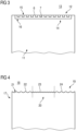
- the surface structure 5 is produced directly together with the production of the rest of the foaming tool 1.
- An alternative separate production of the surface structure is for example in the second embodiment with reference to Fig. 3 shown.
- the surface structure 5 has a plurality of elevations 6 and a plurality of depressions 7, which are produced by means of the additive manufacturing process. According to the invention, the surface structure 5 has two sub-regions 8, 9, wherein the surface structure 5 is differently developed in the two sub-regions 8, 9. The two sub-regions 8, 9 therefore have a differently designed surface structure 5.
- Fig. 2 is the area II-II of Fig. 1 shown enlarged.
- the surface structure 5 is clearly formed by alternately arranged elevations 6 and depressions 7. It is also clear that the surface structure 5 has channels 10 close to the surface through which, for example, a working fluid can be conveyed in order to temper a molded part.
- the arrangement of the channels 10 close to the surface is made possible by the use of the additive manufacturing process, although this would not be possible using conventional manufacturing processes.
- Fig. 3 shows a foaming tool 11 according to a second embodiment.
- the foaming tool 11 has a region 12 which forms a section of a cavity 13.
- the region 12 has a part 14 with a surface structure 15 which is produced by means of an additive manufacturing process.
- the surface structure 15 also has elevations 6 and depressions 7.
- the part 14 is designed as an insert and is inserted into a corresponding recess 16 in the foaming tool 11.
- the part 14 is detachable and can therefore be removed from the foaming tool 11.
- Various inserts can thus be accommodated in the recess 16 so that different surface structures 15 can be introduced into the foaming tool 11 or the part 14 can be replaced.
- Fig. 4 shows a foaming tool 17 according to a third embodiment.
- the foaming tool 17 has a region 19 forming a section of a cavity 18, which has at least a part 20 of a surface structure 21.
- the part 20 of the surface structure 21 is produced by an additive process.
- the foaming tool 17 according to the in Fig. 4 The embodiment shown therefore has three sub-regions 22 to 24, wherein the surface structure 21 in the sub-regions 22 and 24 is the same and differs from the part 20 of the surface structure 21 in the sub-region 23. In other words, the surface structure 21 in the sub-regions 22 and 24 differs from the surface structure 21 in the region 24.
- the surface structure 21 in the sub-areas 22 and 24 was produced together with the rest of the foaming tool 17 directly during its manufacture.
- the part 20 of the surface structure 21 in the sub-area 23 was subsequently applied using an additive process. In other words, the surface structure 21 was supplemented by the sub-area 23.
Landscapes
- Engineering & Computer Science (AREA)
- Mechanical Engineering (AREA)
- Chemical & Material Sciences (AREA)
- Materials Engineering (AREA)
- Physics & Mathematics (AREA)
- Manufacturing & Machinery (AREA)
- Optics & Photonics (AREA)
- Molding Of Porous Articles (AREA)
- Powder Metallurgy (AREA)
Applications Claiming Priority (2)
| Application Number | Priority Date | Filing Date | Title |
|---|---|---|---|
| DE102017118960.2A DE102017118960B4 (de) | 2017-08-18 | 2017-08-18 | Schäumwerkzeug |
| PCT/EP2017/083111 WO2019034269A1 (de) | 2017-08-18 | 2017-12-15 | Schäumwerkzeug |
Publications (3)
| Publication Number | Publication Date |
|---|---|
| EP3668694A1 EP3668694A1 (de) | 2020-06-24 |
| EP3668694B1 true EP3668694B1 (de) | 2024-11-27 |
| EP3668694C0 EP3668694C0 (de) | 2024-11-27 |
Family
ID=60782209
Family Applications (1)
| Application Number | Title | Priority Date | Filing Date |
|---|---|---|---|
| EP17818118.6A Active EP3668694B1 (de) | 2017-08-18 | 2017-12-15 | Schäumwerkzeug |
Country Status (6)
| Country | Link |
|---|---|
| US (2) | US20200254682A1 (https=) |
| EP (1) | EP3668694B1 (https=) |
| JP (1) | JP7499176B2 (https=) |
| CN (1) | CN110997269B (https=) |
| DE (1) | DE102017118960B4 (https=) |
| WO (1) | WO2019034269A1 (https=) |
Families Citing this family (1)
| Publication number | Priority date | Publication date | Assignee | Title |
|---|---|---|---|---|
| EP4342649B1 (de) * | 2022-09-21 | 2026-02-25 | Knauf Industries Gestion | Verfahren zum herstellen eines formteiles |
Citations (5)
| Publication number | Priority date | Publication date | Assignee | Title |
|---|---|---|---|---|
| EP0798095A1 (en) * | 1996-03-26 | 1997-10-01 | Toyota Jidosha Kabushiki Kaisha | Method for manufacturing a mold |
| JP2000037744A (ja) * | 1998-07-24 | 2000-02-08 | Tohoku Munekata Co Ltd | プラスチック製品の肉厚内に微小な気孔を生成する射出成形方法 |
| WO2017022145A1 (ja) * | 2015-07-31 | 2017-02-09 | パナソニックIpマネジメント株式会社 | 三次元形状造形物の製造方法および三次元形状造形物 |
| WO2017134181A1 (en) * | 2016-02-03 | 2017-08-10 | Bockatech Ltd | Method of forming an article |
| DE102017216944A1 (de) * | 2017-09-25 | 2019-03-28 | Adidas Ag | 3D-gedrucktes Mastermodell |
Family Cites Families (27)
| Publication number | Priority date | Publication date | Assignee | Title |
|---|---|---|---|---|
| JPH0310029Y2 (https=) * | 1985-08-02 | 1991-03-13 | ||
| JPH069798Y2 (ja) * | 1988-12-02 | 1994-03-16 | 積水化成品工業株式会社 | 銘 板 |
| US5775402A (en) * | 1995-10-31 | 1998-07-07 | Massachusetts Institute Of Technology | Enhancement of thermal properties of tooling made by solid free form fabrication techniques |
| US5937265A (en) * | 1997-04-24 | 1999-08-10 | Motorola, Inc. | Tooling die insert and rapid method for fabricating same |
| DE19744165C2 (de) | 1997-10-07 | 1999-12-02 | Fraunhofer Ges Forschung | Werkzeug zum Herstellen eines Partikelschaumstoff-Formkörpers und Verfahren zur Herstellung eines solchen Werkzeuges |
| US6224816B1 (en) * | 1998-03-27 | 2001-05-01 | 3D Systems, Inc. | Molding method, apparatus, and device including use of powder metal technology for forming a molding tool with thermal control elements |
| DE10051893C2 (de) * | 1999-10-19 | 2002-08-08 | Fraunhofer Ges Forschung | Verfahren zur Herstellung metallischer Bauteile, insbesondere Werkzeugeinsätze |
| US6609043B1 (en) * | 2000-04-25 | 2003-08-19 | Northrop Grumman Corporation | Method and system for constructing a structural foam part |
| DE10025804A1 (de) | 2000-05-20 | 2001-11-22 | Detlef Kochan | Universelles Werkzeug zur Herstellung von profilierten Körpern |
| US20020187065A1 (en) | 2001-06-06 | 2002-12-12 | Amaya Herman Ernesto | Method for the rapid fabrication of mold inserts |
| JP2003094443A (ja) * | 2001-07-16 | 2003-04-03 | Tokai Model:Kk | 成形型及びその製法 |
| US6749794B2 (en) * | 2001-08-13 | 2004-06-15 | R + S Technik Gmbh | Method and apparatus for molding components with molded-in surface texture |
| DE10229952B4 (de) * | 2002-07-03 | 2007-08-30 | Cl Schutzrechtsverwaltungs Gmbh | Metallisches Werkstück sowie Verfahren zur Herstellung desselben |
| JP3993140B2 (ja) * | 2003-06-25 | 2007-10-17 | 積水化成品工業株式会社 | 発泡樹脂成形型および表示付き発泡樹脂成形品 |
| CA2538358A1 (en) * | 2003-09-11 | 2005-03-24 | The Ex One Company | Layered manufactured articles having small-width fluid conduction vents and methods of making same |
| JP2007223062A (ja) * | 2006-02-21 | 2007-09-06 | Yamasei Seisakusho:Kk | ドライ金型 |
| US7958932B2 (en) * | 2007-07-03 | 2011-06-14 | Fopat Llc | Casting materials |
| DE102007039035B3 (de) | 2007-08-17 | 2009-01-02 | Fraunhofer-Gesellschaft zur Förderung der angewandten Forschung e.V. | Verfahren zum Herstellen eines Bauteils sowie Verwendung des nach dem Verfahren hergestellten Bauteils |
| DE102009016110B4 (de) | 2009-04-03 | 2015-03-05 | Tutech Innovation Gmbh | Verwendung einer Gießform zum Spritzgießen eines Kunststoffgussteils |
| WO2011011524A2 (en) * | 2009-07-21 | 2011-01-27 | Deka Products Limited Partnership | Acoustic dampening for a mechanical device |
| US8567477B2 (en) * | 2012-02-29 | 2013-10-29 | Ford Global Technologies, Llc | Mold core for forming a molding tool |
| JP5912991B2 (ja) * | 2012-08-17 | 2016-04-27 | 株式会社積水化成品山口 | 金型 |
| EP2875928B1 (de) * | 2013-11-25 | 2018-01-03 | Overath GmbH | Verfahren zur Herstellung eines Formwerkzeugs |
| WO2015162585A2 (en) * | 2014-04-25 | 2015-10-29 | Sabic Global Technologies B.V. | Molds and methods of making molds having conforming heating and cooling systems |
| US10960493B2 (en) | 2014-11-11 | 2021-03-30 | DMG Mori USA | Machine tool system and method for additive manufacturing |
| DE102015115821A1 (de) * | 2015-09-18 | 2017-03-23 | Dyemansion Gmbh | Verfahren zum Herstellen und zur Oberflächenbehandlung eines Formteils |
| MX2019008371A (es) * | 2017-04-24 | 2019-09-16 | Rigidcore Group Llc | Material laminado, molde y metodos de fabricacion y uso del material laminado y molde. |
-
2017
- 2017-08-18 DE DE102017118960.2A patent/DE102017118960B4/de active Active
- 2017-12-15 JP JP2020530719A patent/JP7499176B2/ja active Active
- 2017-12-15 WO PCT/EP2017/083111 patent/WO2019034269A1/de not_active Ceased
- 2017-12-15 CN CN201780094032.4A patent/CN110997269B/zh active Active
- 2017-12-15 EP EP17818118.6A patent/EP3668694B1/de active Active
- 2017-12-15 US US16/639,224 patent/US20200254682A1/en not_active Abandoned
-
2024
- 2024-07-10 US US18/768,929 patent/US20240359398A1/en active Pending
Patent Citations (6)
| Publication number | Priority date | Publication date | Assignee | Title |
|---|---|---|---|---|
| EP0798095A1 (en) * | 1996-03-26 | 1997-10-01 | Toyota Jidosha Kabushiki Kaisha | Method for manufacturing a mold |
| JP2000037744A (ja) * | 1998-07-24 | 2000-02-08 | Tohoku Munekata Co Ltd | プラスチック製品の肉厚内に微小な気孔を生成する射出成形方法 |
| WO2017022145A1 (ja) * | 2015-07-31 | 2017-02-09 | パナソニックIpマネジメント株式会社 | 三次元形状造形物の製造方法および三次元形状造形物 |
| DE112016003471T5 (de) * | 2015-07-31 | 2018-04-19 | Panasonic Intellectual Property Management Co., Ltd. | Verfahren zur Herstellung eines dreidimensional geformten Formerzeugnisses und dreidimensional geformtes Formerzeugnis |
| WO2017134181A1 (en) * | 2016-02-03 | 2017-08-10 | Bockatech Ltd | Method of forming an article |
| DE102017216944A1 (de) * | 2017-09-25 | 2019-03-28 | Adidas Ag | 3D-gedrucktes Mastermodell |
Also Published As
| Publication number | Publication date |
|---|---|
| DE102017118960A1 (de) | 2019-02-21 |
| JP7499176B2 (ja) | 2024-06-13 |
| CN110997269A (zh) | 2020-04-10 |
| EP3668694A1 (de) | 2020-06-24 |
| CN110997269B (zh) | 2022-08-05 |
| DE102017118960B4 (de) | 2019-07-11 |
| EP3668694C0 (de) | 2024-11-27 |
| WO2019034269A1 (de) | 2019-02-21 |
| JP2020531330A (ja) | 2020-11-05 |
| US20240359398A1 (en) | 2024-10-31 |
| US20200254682A1 (en) | 2020-08-13 |
Similar Documents
| Publication | Publication Date | Title |
|---|---|---|
| EP3017343B1 (de) | Verfahren zum herstellen eines dreidimensionalen objekts | |
| DE60202175T2 (de) | Formwerkzeug und Verfahren zu dessen Herstellung | |
| DE69910384T2 (de) | Verfahren zur herstellung von feuerfesten formkörpern | |
| DE60115136T2 (de) | Herstellung von dreidimensionalen Gegenständen durch kontrollierte Photohärtung | |
| EP2301743B1 (de) | Verfahren und vorrichtung zum herstellen eines formkörpers durch schichtweisen aufbau | |
| DE102013203374A1 (de) | Additive fertigungstechnologien zum erzeugen von formen für matrizenkomponenten | |
| DE19528215A1 (de) | Verfahren zur Herstellung von dreidimensionalen Modellen und Formen | |
| DE102007039035B3 (de) | Verfahren zum Herstellen eines Bauteils sowie Verwendung des nach dem Verfahren hergestellten Bauteils | |
| DE60002344T2 (de) | Stereolithografisches verfahren zur herstellung von gegenständen mit verschiedene dichten aufweisenden zonen | |
| DE102012016309A1 (de) | Verfahren zur Herstellung einer Kernschicht eines Leichtbauelementes sowie Leichtbauelement | |
| DE112016003471T5 (de) | Verfahren zur Herstellung eines dreidimensional geformten Formerzeugnisses und dreidimensional geformtes Formerzeugnis | |
| EP3338918A1 (de) | Schichtbauvorrichtung und schichtbauverfahren zum additiven herstellen zumindest eines bauteilbereichs eines bauteils | |
| EP3668694B1 (de) | Schäumwerkzeug | |
| DE102014221423B4 (de) | Verfahren zur Herstellung großer Warmumformwerkzeuge mittels eines generativen Fertigungsverfahrens | |
| DE19900597A1 (de) | Blechumformungswerkzeug und Verfahren zu seiner Herstellung | |
| DE102009016110A1 (de) | Verfahren zur Herstellung eines Formeinsatzes für eine Gießform | |
| EP3661718B1 (de) | Werkzeug | |
| DE10014744A1 (de) | Verfahren zur Herstellung von metallischen Hohlformen | |
| DE19744165C2 (de) | Werkzeug zum Herstellen eines Partikelschaumstoff-Formkörpers und Verfahren zur Herstellung eines solchen Werkzeuges | |
| DE102004029973B4 (de) | Umformwerkzeug und Verfahren zur Herstellung eines Umformwerkzeugs | |
| EP3687757B1 (de) | Werkzeug zur verarbeitung schäumbarer und/oder vorgeschäumter kunststoffpartikel | |
| EP3416813B1 (de) | Bearbeitungswerkzeug und verfahren zu seiner herstellung mittels eines generativen schichtbauprozesses | |
| WO2019175383A1 (de) | Spritz- oder druckkopf und spritz- oder druckkopfanordnung | |
| DE102018216792A1 (de) | 3D-Druckvorrichtung | |
| DE102017215189A1 (de) | Formwerkzeug zur Herstellung mindestens eines Gussteiles |
Legal Events
| Date | Code | Title | Description |
|---|---|---|---|
| STAA | Information on the status of an ep patent application or granted ep patent |
Free format text: STATUS: UNKNOWN |
|
| STAA | Information on the status of an ep patent application or granted ep patent |
Free format text: STATUS: THE INTERNATIONAL PUBLICATION HAS BEEN MADE |
|
| PUAI | Public reference made under article 153(3) epc to a published international application that has entered the european phase |
Free format text: ORIGINAL CODE: 0009012 |
|
| STAA | Information on the status of an ep patent application or granted ep patent |
Free format text: STATUS: REQUEST FOR EXAMINATION WAS MADE |
|
| 17P | Request for examination filed |
Effective date: 20200212 |
|
| AK | Designated contracting states |
Kind code of ref document: A1 Designated state(s): AL AT BE BG CH CY CZ DE DK EE ES FI FR GB GR HR HU IE IS IT LI LT LU LV MC MK MT NL NO PL PT RO RS SE SI SK SM TR |
|
| AX | Request for extension of the european patent |
Extension state: BA ME |
|
| DAV | Request for validation of the european patent (deleted) | ||
| DAX | Request for extension of the european patent (deleted) | ||
| RAP3 | Party data changed (applicant data changed or rights of an application transferred) |
Owner name: SIEGFRIED HOFMANN GMBH |
|
| STAA | Information on the status of an ep patent application or granted ep patent |
Free format text: STATUS: EXAMINATION IS IN PROGRESS |
|
| 17Q | First examination report despatched |
Effective date: 20220224 |
|
| P01 | Opt-out of the competence of the unified patent court (upc) registered |
Effective date: 20230530 |
|
| GRAP | Despatch of communication of intention to grant a patent |
Free format text: ORIGINAL CODE: EPIDOSNIGR1 |
|
| STAA | Information on the status of an ep patent application or granted ep patent |
Free format text: STATUS: GRANT OF PATENT IS INTENDED |
|
| GRAS | Grant fee paid |
Free format text: ORIGINAL CODE: EPIDOSNIGR3 |
|
| GRAA | (expected) grant |
Free format text: ORIGINAL CODE: 0009210 |
|
| STAA | Information on the status of an ep patent application or granted ep patent |
Free format text: STATUS: THE PATENT HAS BEEN GRANTED |
|
| INTG | Intention to grant announced |
Effective date: 20240927 |
|
| AK | Designated contracting states |
Kind code of ref document: B1 Designated state(s): AL AT BE BG CH CY CZ DE DK EE ES FI FR GB GR HR HU IE IS IT LI LT LU LV MC MK MT NL NO PL PT RO RS SE SI SK SM TR |
|
| REG | Reference to a national code |
Ref country code: GB Ref legal event code: FG4D Free format text: NOT ENGLISH |
|
| REG | Reference to a national code |
Ref country code: CH Ref legal event code: EP |
|
| RAP4 | Party data changed (patent owner data changed or rights of a patent transferred) |
Owner name: SIEGFRIED HOFMANN GMBH |
|
| REG | Reference to a national code |
Ref country code: IE Ref legal event code: FG4D Free format text: LANGUAGE OF EP DOCUMENT: GERMAN |
|
| REG | Reference to a national code |
Ref country code: DE Ref legal event code: R096 Ref document number: 502017016581 Country of ref document: DE |
|
| U01 | Request for unitary effect filed |
Effective date: 20241209 |
|
| P04 | Withdrawal of opt-out of the competence of the unified patent court (upc) registered |
Free format text: CASE NUMBER: APP_66591/2024 Effective date: 20241216 |
|
| U07 | Unitary effect registered |
Designated state(s): AT BE BG DE DK EE FI FR IT LT LU LV MT NL PT RO SE SI Effective date: 20241219 |
|
| U20 | Renewal fee for the european patent with unitary effect paid |
Year of fee payment: 8 Effective date: 20241219 |
|
| PG25 | Lapsed in a contracting state [announced via postgrant information from national office to epo] |
Ref country code: IS Free format text: LAPSE BECAUSE OF FAILURE TO SUBMIT A TRANSLATION OF THE DESCRIPTION OR TO PAY THE FEE WITHIN THE PRESCRIBED TIME-LIMIT Effective date: 20250327 Ref country code: HR Free format text: LAPSE BECAUSE OF FAILURE TO SUBMIT A TRANSLATION OF THE DESCRIPTION OR TO PAY THE FEE WITHIN THE PRESCRIBED TIME-LIMIT Effective date: 20241127 |
|
| PG25 | Lapsed in a contracting state [announced via postgrant information from national office to epo] |
Ref country code: ES Free format text: LAPSE BECAUSE OF FAILURE TO SUBMIT A TRANSLATION OF THE DESCRIPTION OR TO PAY THE FEE WITHIN THE PRESCRIBED TIME-LIMIT Effective date: 20241127 |
|
| PG25 | Lapsed in a contracting state [announced via postgrant information from national office to epo] |
Ref country code: NO Free format text: LAPSE BECAUSE OF FAILURE TO SUBMIT A TRANSLATION OF THE DESCRIPTION OR TO PAY THE FEE WITHIN THE PRESCRIBED TIME-LIMIT Effective date: 20250227 |
|
| PG25 | Lapsed in a contracting state [announced via postgrant information from national office to epo] |
Ref country code: GR Free format text: LAPSE BECAUSE OF FAILURE TO SUBMIT A TRANSLATION OF THE DESCRIPTION OR TO PAY THE FEE WITHIN THE PRESCRIBED TIME-LIMIT Effective date: 20250228 |
|
| PG25 | Lapsed in a contracting state [announced via postgrant information from national office to epo] |
Ref country code: PL Free format text: LAPSE BECAUSE OF FAILURE TO SUBMIT A TRANSLATION OF THE DESCRIPTION OR TO PAY THE FEE WITHIN THE PRESCRIBED TIME-LIMIT Effective date: 20241127 |
|
| PG25 | Lapsed in a contracting state [announced via postgrant information from national office to epo] |
Ref country code: RS Free format text: LAPSE BECAUSE OF FAILURE TO SUBMIT A TRANSLATION OF THE DESCRIPTION OR TO PAY THE FEE WITHIN THE PRESCRIBED TIME-LIMIT Effective date: 20250227 |
|
| PG25 | Lapsed in a contracting state [announced via postgrant information from national office to epo] |
Ref country code: SM Free format text: LAPSE BECAUSE OF FAILURE TO SUBMIT A TRANSLATION OF THE DESCRIPTION OR TO PAY THE FEE WITHIN THE PRESCRIBED TIME-LIMIT Effective date: 20241127 |
|
| PG25 | Lapsed in a contracting state [announced via postgrant information from national office to epo] |
Ref country code: SK Free format text: LAPSE BECAUSE OF FAILURE TO SUBMIT A TRANSLATION OF THE DESCRIPTION OR TO PAY THE FEE WITHIN THE PRESCRIBED TIME-LIMIT Effective date: 20241127 |
|
| PG25 | Lapsed in a contracting state [announced via postgrant information from national office to epo] |
Ref country code: CZ Free format text: LAPSE BECAUSE OF FAILURE TO SUBMIT A TRANSLATION OF THE DESCRIPTION OR TO PAY THE FEE WITHIN THE PRESCRIBED TIME-LIMIT Effective date: 20241127 |
|
| REG | Reference to a national code |
Ref country code: CH Ref legal event code: PL |
|
| PG25 | Lapsed in a contracting state [announced via postgrant information from national office to epo] |
Ref country code: MC Free format text: LAPSE BECAUSE OF FAILURE TO SUBMIT A TRANSLATION OF THE DESCRIPTION OR TO PAY THE FEE WITHIN THE PRESCRIBED TIME-LIMIT Effective date: 20241127 |
|
| PLBE | No opposition filed within time limit |
Free format text: ORIGINAL CODE: 0009261 |
|
| STAA | Information on the status of an ep patent application or granted ep patent |
Free format text: STATUS: NO OPPOSITION FILED WITHIN TIME LIMIT |
|
| PG25 | Lapsed in a contracting state [announced via postgrant information from national office to epo] |
Ref country code: CH Free format text: LAPSE BECAUSE OF NON-PAYMENT OF DUE FEES Effective date: 20241231 |
|
| PG25 | Lapsed in a contracting state [announced via postgrant information from national office to epo] |
Ref country code: IE Free format text: LAPSE BECAUSE OF NON-PAYMENT OF DUE FEES Effective date: 20241215 |
|
| GBPC | Gb: european patent ceased through non-payment of renewal fee |
Effective date: 20250227 |
|
| 26N | No opposition filed |
Effective date: 20250828 |
|
| PG25 | Lapsed in a contracting state [announced via postgrant information from national office to epo] |
Ref country code: GB Free format text: LAPSE BECAUSE OF NON-PAYMENT OF DUE FEES Effective date: 20250227 |
|
| U20 | Renewal fee for the european patent with unitary effect paid |
Year of fee payment: 9 Effective date: 20251210 |