EP3668405B1 - Computertomographievorrichtung - Google Patents
Computertomographievorrichtung Download PDFInfo
- Publication number
- EP3668405B1 EP3668405B1 EP18759896.6A EP18759896A EP3668405B1 EP 3668405 B1 EP3668405 B1 EP 3668405B1 EP 18759896 A EP18759896 A EP 18759896A EP 3668405 B1 EP3668405 B1 EP 3668405B1
- Authority
- EP
- European Patent Office
- Prior art keywords
- platform
- relative
- gantry
- computed tomography
- displacement
- Prior art date
- Legal status (The legal status is an assumption and is not a legal conclusion. Google has not performed a legal analysis and makes no representation as to the accuracy of the status listed.)
- Active
Links
Images


Classifications
-
- A—HUMAN NECESSITIES
- A61—MEDICAL OR VETERINARY SCIENCE; HYGIENE
- A61B—DIAGNOSIS; SURGERY; IDENTIFICATION
- A61B6/00—Apparatus or devices for radiation diagnosis; Apparatus or devices for radiation diagnosis combined with radiation therapy equipment
- A61B6/50—Apparatus or devices for radiation diagnosis; Apparatus or devices for radiation diagnosis combined with radiation therapy equipment specially adapted for specific body parts; specially adapted for specific clinical applications
- A61B6/508—Apparatus or devices for radiation diagnosis; Apparatus or devices for radiation diagnosis combined with radiation therapy equipment specially adapted for specific body parts; specially adapted for specific clinical applications for non-human patients
-
- A—HUMAN NECESSITIES
- A61—MEDICAL OR VETERINARY SCIENCE; HYGIENE
- A61B—DIAGNOSIS; SURGERY; IDENTIFICATION
- A61B6/00—Apparatus or devices for radiation diagnosis; Apparatus or devices for radiation diagnosis combined with radiation therapy equipment
- A61B6/02—Arrangements for diagnosis sequentially in different planes; Stereoscopic radiation diagnosis
- A61B6/03—Computed tomography [CT]
- A61B6/032—Transmission computed tomography [CT]
-
- A—HUMAN NECESSITIES
- A61—MEDICAL OR VETERINARY SCIENCE; HYGIENE
- A61B—DIAGNOSIS; SURGERY; IDENTIFICATION
- A61B6/00—Apparatus or devices for radiation diagnosis; Apparatus or devices for radiation diagnosis combined with radiation therapy equipment
- A61B6/02—Arrangements for diagnosis sequentially in different planes; Stereoscopic radiation diagnosis
- A61B6/03—Computed tomography [CT]
- A61B6/032—Transmission computed tomography [CT]
- A61B6/035—Mechanical aspects of CT
-
- A—HUMAN NECESSITIES
- A61—MEDICAL OR VETERINARY SCIENCE; HYGIENE
- A61B—DIAGNOSIS; SURGERY; IDENTIFICATION
- A61B6/00—Apparatus or devices for radiation diagnosis; Apparatus or devices for radiation diagnosis combined with radiation therapy equipment
- A61B6/02—Arrangements for diagnosis sequentially in different planes; Stereoscopic radiation diagnosis
- A61B6/03—Computed tomography [CT]
- A61B6/037—Emission tomography
-
- A—HUMAN NECESSITIES
- A61—MEDICAL OR VETERINARY SCIENCE; HYGIENE
- A61B—DIAGNOSIS; SURGERY; IDENTIFICATION
- A61B6/00—Apparatus or devices for radiation diagnosis; Apparatus or devices for radiation diagnosis combined with radiation therapy equipment
- A61B6/04—Positioning of patients; Tiltable beds or the like
- A61B6/0407—Supports, e.g. tables or beds, for the body or parts of the body
-
- A—HUMAN NECESSITIES
- A61—MEDICAL OR VETERINARY SCIENCE; HYGIENE
- A61B—DIAGNOSIS; SURGERY; IDENTIFICATION
- A61B6/00—Apparatus or devices for radiation diagnosis; Apparatus or devices for radiation diagnosis combined with radiation therapy equipment
- A61B6/04—Positioning of patients; Tiltable beds or the like
- A61B6/0487—Motor-assisted positioning
-
- A—HUMAN NECESSITIES
- A61—MEDICAL OR VETERINARY SCIENCE; HYGIENE
- A61B—DIAGNOSIS; SURGERY; IDENTIFICATION
- A61B6/00—Apparatus or devices for radiation diagnosis; Apparatus or devices for radiation diagnosis combined with radiation therapy equipment
- A61B6/10—Safety means specially adapted therefor
- A61B6/102—Protection against mechanical damage, e.g. anti-collision devices
-
- A—HUMAN NECESSITIES
- A61—MEDICAL OR VETERINARY SCIENCE; HYGIENE
- A61B—DIAGNOSIS; SURGERY; IDENTIFICATION
- A61B6/00—Apparatus or devices for radiation diagnosis; Apparatus or devices for radiation diagnosis combined with radiation therapy equipment
- A61B6/44—Constructional features of apparatus for radiation diagnosis
- A61B6/4405—Constructional features of apparatus for radiation diagnosis the apparatus being movable or portable, e.g. handheld or mounted on a trolley
-
- A—HUMAN NECESSITIES
- A61—MEDICAL OR VETERINARY SCIENCE; HYGIENE
- A61B—DIAGNOSIS; SURGERY; IDENTIFICATION
- A61B6/00—Apparatus or devices for radiation diagnosis; Apparatus or devices for radiation diagnosis combined with radiation therapy equipment
- A61B6/44—Constructional features of apparatus for radiation diagnosis
- A61B6/4411—Constructional features of apparatus for radiation diagnosis the apparatus being modular
-
- A—HUMAN NECESSITIES
- A61—MEDICAL OR VETERINARY SCIENCE; HYGIENE
- A61B—DIAGNOSIS; SURGERY; IDENTIFICATION
- A61B6/00—Apparatus or devices for radiation diagnosis; Apparatus or devices for radiation diagnosis combined with radiation therapy equipment
- A61B6/44—Constructional features of apparatus for radiation diagnosis
- A61B6/4429—Constructional features of apparatus for radiation diagnosis related to the mounting of source units and detector units
-
- A—HUMAN NECESSITIES
- A61—MEDICAL OR VETERINARY SCIENCE; HYGIENE
- A61B—DIAGNOSIS; SURGERY; IDENTIFICATION
- A61B6/00—Apparatus or devices for radiation diagnosis; Apparatus or devices for radiation diagnosis combined with radiation therapy equipment
- A61B6/44—Constructional features of apparatus for radiation diagnosis
- A61B6/4429—Constructional features of apparatus for radiation diagnosis related to the mounting of source units and detector units
- A61B6/4435—Constructional features of apparatus for radiation diagnosis related to the mounting of source units and detector units the source unit and the detector unit being coupled by a rigid structure
-
- A—HUMAN NECESSITIES
- A61—MEDICAL OR VETERINARY SCIENCE; HYGIENE
- A61B—DIAGNOSIS; SURGERY; IDENTIFICATION
- A61B6/00—Apparatus or devices for radiation diagnosis; Apparatus or devices for radiation diagnosis combined with radiation therapy equipment
- A61B6/44—Constructional features of apparatus for radiation diagnosis
- A61B6/4476—Constructional features of apparatus for radiation diagnosis related to motor-assisted motion of the source unit
-
- A—HUMAN NECESSITIES
- A61—MEDICAL OR VETERINARY SCIENCE; HYGIENE
- A61B—DIAGNOSIS; SURGERY; IDENTIFICATION
- A61B6/00—Apparatus or devices for radiation diagnosis; Apparatus or devices for radiation diagnosis combined with radiation therapy equipment
- A61B6/44—Constructional features of apparatus for radiation diagnosis
- A61B6/4476—Constructional features of apparatus for radiation diagnosis related to motor-assisted motion of the source unit
- A61B6/4482—Constructional features of apparatus for radiation diagnosis related to motor-assisted motion of the source unit involving power assist circuits
-
- A—HUMAN NECESSITIES
- A61—MEDICAL OR VETERINARY SCIENCE; HYGIENE
- A61D—VETERINARY INSTRUMENTS, IMPLEMENTS, TOOLS, OR METHODS
- A61D99/00—Subject matter not provided for in other groups of this subclass
-
- A—HUMAN NECESSITIES
- A61—MEDICAL OR VETERINARY SCIENCE; HYGIENE
- A61B—DIAGNOSIS; SURGERY; IDENTIFICATION
- A61B6/00—Apparatus or devices for radiation diagnosis; Apparatus or devices for radiation diagnosis combined with radiation therapy equipment
- A61B6/50—Apparatus or devices for radiation diagnosis; Apparatus or devices for radiation diagnosis combined with radiation therapy equipment specially adapted for specific body parts; specially adapted for specific clinical applications
- A61B6/501—Apparatus or devices for radiation diagnosis; Apparatus or devices for radiation diagnosis combined with radiation therapy equipment specially adapted for specific body parts; specially adapted for specific clinical applications for diagnosis of the head, e.g. neuroimaging or craniography
Definitions
- the invention relates to a computed tomography device for examining a body part of a large animal and a method for examining a body part of a large animal with a computed tomography device.
- a computed tomography (CT) device typically has a gantry designed as a ring tunnel and a CT table which can be moved into the central opening of the ring-shaped gantry and on which a patient or an examination object can be placed.
- a CT tube and a detector system opposite the CT tube are arranged eccentrically in the gantry and rotate in the ring tunnel during a CT examination.
- the CT tube emits a fan beam of X-rays in the direction of the detector system.
- the X-rays in the illuminated area are attenuated to different degrees.
- the detector detects a two-dimensional projection of the usually three-dimensional illuminated object, the projection representing an intensity map of the detected X-rays.
- a standing surface is understood to mean a solid base that is located on the side of the gantry that is opposite the CT table.
- the stand is outside of the computed tomography device.
- a large animal to be examined stands stationary on the standing surface.
- a rotary movement of the displacement motor that drives the threaded spindle can be converted into a relative displacement movement of the mating thread and thus of the platform with respect to the threaded spindle. So it is a spindle drive.
- the CT device preferably comprises a CT motor for motor-driven retraction of the CT table into the gantry.
- the coupling is designed in such a way that a CT drive is tapped directly by a mechanical coupling and transmitted to the displacement drive.
- a mechanical coupling can be implemented, for example, by a spindle, via which the CT drive and the displacement drive are connected to one another.
- the coupling of the CT drive and the displacement drive is designed in such a way that the speed and / or the position of the CT table and / or the platform is measured by a corresponding speed or position sensor.
- a speed signal and / or position signal which accordingly represent a measured speed or position, can then be transmitted to the CT motor and / or the displacement motor as a manipulated variable and used to regulate the CT motor and / or the displacement motor.
- Speed and / or position then represent manipulated variables with which the CT motor and / or the displacement motor, for example the speed as a controlled variable, can be specifically influenced.
- the lifting device comprises at least one lifting motor which is connected to one of the threaded spindles to drive at least one of the plurality of threaded spindles of the lifting device and is designed to provide a lifting drive for lifting or lowering the platform relative to the standing surface of a large animal.
- the lifting motor is preferably designed to provide a power which is sufficient to drive a threaded spindle and thus to raise or lower the base plate and the platform with the CT device arranged on it.
- the lifting motor can also be connected to one or more threaded spindles via belts.
- the lifting motor is preferably an electric motor.
- the lifting device preferably comprises at least one hydraulic pressure cylinder.
- the pressure cylinder is preferably arranged in relation to the base plate in such a way that the base plate can be raised or lowered relative to the standing surface by applying pressure to the pressure cylinder.
- the computed tomography device has an examination stand.
- the examination stand preferably comprises a holding device and a support held by the holding device on which a body part of a large animal can be placed.
- the examination stand is preferably arranged in such a way that at least the shelf is not moved with the platform while the platform is being moved by the displacement device.
- the shelf is preferably designed in such a way that its height can be adjusted in relation to the CT device. It is conceivable that the tray is arranged on the holding device in such a way that the tray can be removed from the holding device and attached again to the holding device at a different height.
- the shelf can be attached to the holding device by a screw connection and the holding device can have holes along its height for fastening the shelf by means of the screw connection.
- the height of the shelf in relation to a large animal to be examined can therefore advantageously be adapted to the CT device in accordance with the height of the large animal.
- the shelf is preferably arranged and set at a height such that the shelf can be moved into the opening of the annular gantry by moving the platform with the CT device, in particular to the extent that the shelf protrudes through the opening of the annular gantry.
- the gantry can then move over the shelf, so that the shelf is located at least with a partial area within the opening of the ring-shaped gantry during a CT examination.
- a computed tomography device comprises a base plate on which the platform with the mounted CT device is arranged
- the holding device is preferably attached to the base plate, so that the holding device and the tray move together with the base plate when they are moved by a lifting device relative to the Stand surface is raised or lowered.
- the CT table is decoupled and can therefore be moved freely in relation to the rest of the CT device. For an outside observer it then looks as if the CT table appears to be stationary while the platform is being shifted and the gantry seems to move over the CT table.
- the gantry preferably has a laser which is arranged and designed in the gantry in such a way that during a CT examination the area currently being examined is made visible by emitted laser light.
- Computed tomography devices described above can also be used within a computed tomography examination arrangement, the computed tomography examination arrangement comprising a computed tomography device, a standing surface for a large animal and a pit in the ground.
- the computed tomography device is arranged in the ground pit so that at least part of the computed tomography device is at a lower level compared to the floor space.
- the standing area is located outside the floor pit, bordering on that side wall of the floor pit that is closest to the gantry of the computed tomography device.
- the above-mentioned object of the invention is achieved by a method for examining a body part of a large animal with a computer tomography device.
- the computed tomography device has a computed tomography (CT) device and a platform on which the CT device is mounted.
- CT device comprises an annular gantry and a CT table for holding a part of the body of a large animal to be examined.
- the CT table and the gantry are movably connected to one another so that the CT table can be moved into an opening in the ring-shaped gantry.
- the computed tomography apparatus 100 has a CT device 102, which comprises an annular gantry 104 and a CT table 106.
- the gantry 104 is designed as a ring tunnel in which a CT tube and a detector (both not shown) are arranged opposite the CT tube.
- the annular gantry 104 has an opening 108 in the center.
- the CT table 106 and the gantry 104 are movably connected to one another so that the CT table 106 can be moved into the opening 108 of the ring-shaped gantry 104.
- the CT device 102 shown is basically available on the market.
- the computed tomography device 100 furthermore has a platform 110 on which the CT device 102 is mounted.
- the platform 110 is arranged on a floor plate 112, a rail system 114 being located between the floor plate 112 and the platform 110.
- the rail system 114 enables the base plate 112 and the platform 110 to be displaced back and forth with comparatively little friction in those directions in which the CT table 106 is also movable.
- the rail system 114 is an element of a displacement device, which also has a displacement motor (not shown) and a threaded spindle (not shown) that can be driven by the displacement motor. having, a mating thread (not shown) being slidably mounted on the threaded spindle.
- the CT table 106 would then move into the opening 108 of the gantry 104 as intended and thus actually towards a large animal standing behind it.
- the platform 110 with the CT device 102 moves away from the standing surface of the large animal at the same speed in terms of amount.
- a body part which is placed or laid on the CT table remains in an immovable position relative to the standing surface, while the gantry 104 appears to move over the body part.
- the CT table 106 seems to be stationary in this operating state and the gantry 104 seems to be moving over the CT table 106 on which a body part of a large animal to be examined can be placed or placed.
- the threaded spindles 120 are elements of a lifting device and, with respect to the base plate 112, are arranged perpendicularly in the direction of the platform 110 laterally on the base plate 112.
- Each of the threaded spindles 120 is connected to the base plate 112 via a displaceably mounted counter thread 122.
- the mating threads 122 are therefore firmly connected to the base plate 112 and are each slidably mounted on a threaded spindle 120.
- the base plate 112 and the platform 110 arranged on the base plate 112 can be raised or lowered with the CT device 102.
- two of the threaded spindles 120 are each connected to a lifting motor 124.
- the counter-threads 122 of the lifting device which are arranged in columns 118 on the same longitudinal side of the floor plate, are mechanically connected to one another by a synchronization device 126.
- the synchronization devices 126 are designed as continuous connecting elements and each mechanically couple two mating threads on one longitudinal side of the base plate to one another.
- the connecting elements 126 are also connected to the base plate 112, so that the connection of the mating thread 122 to the base plate 112 is additionally supported.
- the lifting device has at least one hydraulic pressure cylinder in addition or as an alternative to a spindle drive.
- a pressure cylinder is arranged in relation to a base plate in such a way that the base plate can be raised or lowered relative to a standing surface by applying pressure to the pressure cylinder.
- the computed tomography device 202 is analogous to that in relation to FIG Figure 1 described computed tomography device and comprises in particular a CT device 208 with a gantry 210 and a CT table 212, which can be moved with a CT motor into an opening of the ring-shaped gantry 208.
- the CT device 208 is mounted on a platform 214 which is arranged on a floor plate 216.
- the platform with the CT device 208 can be moved back and forth relative to the standing surface 206 by a displacement device (not shown) in the direction in which the CT table 212 is also movable.
- the base plate 216 can be raised and lowered by a lifting device 218, so that the CT device 208 mounted on the platform 214 can be both vertically raised and lowered and also horizontally moved relative to the standing surface 206 by means of the lifting device 218 and the displacement device.
- the standing surface 206 is located outside of the floor pit 204 and specifically adjacent to that side wall 220 of the floor pit 206 which is closest to the gantry 210 of the computed tomography device 202.
- the floor pit 204 has a depth which is dimensioned such that the CT table 212 of the CT device 208 when the CT device 202 is as shown in FIG Figure 2 shown by the lifting device 218 is completely lowered, is located at the same height as the standing surface 206.
- the head of a large animal can be positioned above the gantry, so that the body of the large animal is then located directly in front of the gantry.
- a foreleg of the large animal can then, for example, be placed obliquely forward on the CT table 212 so that the gantry 210 appears to move over the foreleg relative to the standing surface 206 of the large animal during a CT examination.
- a rear leg of a large animal can accordingly be placed obliquely backwards on the CT table 212 from the large animal.
- the CT device 210 can be raised up to two meters by the lifting device 218. In an embodiment not shown here, a CT device can be raised beyond two meters, for example up to three meters. In the raised state, for example, a CT examination of the head and neck of a large animal can then be carried out. With the computed tomography examination arrangement 200 shown, both the limbs and the head or the neck of a stationary large animal can be examined. In particular, with the computed tomography examination arrangement 200 shown, the head, neck and forelegs of a stationary large animal can be examined one after the other with the same commercially available CT device 202 without the large animal having to change or give up its stationary position on the standing surface 206.
- the tray 304 is attached to the holding device 302 and is designed in such a way that a body part of a large animal, here a horse, can be placed on the tray 304.
- the holding device is attached to a base plate 306, so that the holding device 302 and shelf 304 do not move with the platform 308 while a displacement device is used.
- the base plate 306 is raised or lowered by a lifting device, the holding device 302 and the tray 304 move together with the base plate 306, so that the tray 304 can be adjusted to a certain height with respect to the large animal to be examined.
- the tray 304 can thus be adapted to the height of a large animal to be examined and in particular of a body part to be examined, for example to the height of a horse's head or neck.
- the shelf 304 is arranged at a height with respect to the CT device that the shelf 304 can be moved into the opening 310 of the annular gantry 312 by moving the platform 308 with the CT device, in particular to the extent that the shelf 304 protrudes through the opening 310 of the annular gantry 312.
- the gantry 312 thus appears to move over the shelf 304 for an outside observer.
- a metal construction 314 is attached to the computer tomography device 300 on the side facing the standing surface of a large animal.
- the metal construction 314 serves as protection for the CT device against the action of the large animal, for example a step, on the CT device.
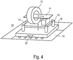
- a computed tomography device 15 for examining a body part of a large animal.
- the computed tomography device 15 comprises a CT device which comprises a gantry 12 and a CT table 11.
- the CT device is arranged on a base plate 13 which can be raised or lowered vertically by means of a lifting device 16.
- the gantry 12 is arranged immovably on the base plate 13.
- the CT table 16 is arranged horizontally movably on the base plate 13 and can move horizontally relative to the gantry and / or the base plate.
- the base plate 13 and the lifting device 16 are arranged on a platform 18.
- the platform 18 is arranged on solid ground 14, for example in a pit, and can be shifted horizontally with respect to the ground 14 by means of a displacement device 20.
Landscapes
- Health & Medical Sciences (AREA)
- Life Sciences & Earth Sciences (AREA)
- Engineering & Computer Science (AREA)
- Medical Informatics (AREA)
- Veterinary Medicine (AREA)
- Public Health (AREA)
- General Health & Medical Sciences (AREA)
- Animal Behavior & Ethology (AREA)
- Biophysics (AREA)
- High Energy & Nuclear Physics (AREA)
- Optics & Photonics (AREA)
- Pathology (AREA)
- Radiology & Medical Imaging (AREA)
- Biomedical Technology (AREA)
- Heart & Thoracic Surgery (AREA)
- Molecular Biology (AREA)
- Surgery (AREA)
- Nuclear Medicine, Radiotherapy & Molecular Imaging (AREA)
- Physics & Mathematics (AREA)
- Pulmonology (AREA)
- Theoretical Computer Science (AREA)
- Oral & Maxillofacial Surgery (AREA)
- Dentistry (AREA)
- Wood Science & Technology (AREA)
- Zoology (AREA)
- Apparatus For Radiation Diagnosis (AREA)
Priority Applications (1)
| Application Number | Priority Date | Filing Date | Title |
|---|---|---|---|
| EP21151196.9A EP3838158B1 (de) | 2017-08-17 | 2018-08-17 | Computertomographievorrichtung |
Applications Claiming Priority (2)
| Application Number | Priority Date | Filing Date | Title |
|---|---|---|---|
| DE102017007722.3A DE102017007722B4 (de) | 2017-08-17 | 2017-08-17 | Absenkbarer Computertomograph |
| PCT/EP2018/072372 WO2019034793A1 (de) | 2017-08-17 | 2018-08-17 | Computertomographievorrichtung |
Related Child Applications (1)
| Application Number | Title | Priority Date | Filing Date |
|---|---|---|---|
| EP21151196.9A Division EP3838158B1 (de) | 2017-08-17 | 2018-08-17 | Computertomographievorrichtung |
Publications (2)
| Publication Number | Publication Date |
|---|---|
| EP3668405A1 EP3668405A1 (de) | 2020-06-24 |
| EP3668405B1 true EP3668405B1 (de) | 2021-01-13 |
Family
ID=63405186
Family Applications (2)
| Application Number | Title | Priority Date | Filing Date |
|---|---|---|---|
| EP18759896.6A Active EP3668405B1 (de) | 2017-08-17 | 2018-08-17 | Computertomographievorrichtung |
| EP21151196.9A Active EP3838158B1 (de) | 2017-08-17 | 2018-08-17 | Computertomographievorrichtung |
Family Applications After (1)
| Application Number | Title | Priority Date | Filing Date |
|---|---|---|---|
| EP21151196.9A Active EP3838158B1 (de) | 2017-08-17 | 2018-08-17 | Computertomographievorrichtung |
Country Status (6)
| Country | Link |
|---|---|
| US (4) | US11213267B2 (da) |
| EP (2) | EP3668405B1 (da) |
| DE (2) | DE102017007722B4 (da) |
| DK (1) | DK3668405T3 (da) |
| PL (1) | PL3838158T3 (da) |
| WO (1) | WO2019034793A1 (da) |
Families Citing this family (6)
| Publication number | Priority date | Publication date | Assignee | Title |
|---|---|---|---|---|
| DE102017007722B4 (de) * | 2017-08-17 | 2019-03-07 | Thorben Schulze | Absenkbarer Computertomograph |
| DE102021106405B4 (de) | 2021-03-16 | 2023-03-09 | Haufe und Schluck Patent GbR (vertretungsberechtigter Gesellschafter: Günther Haufe, 59399 Olfen) | Vorrichtung zur Untersuchung von Körperteilen eines Großtieres |
| IT202100023609A1 (it) * | 2021-09-14 | 2023-03-14 | Jolanda Luongo | Unità mobile di tomografia computerizzata |
| DE102022132977A1 (de) * | 2022-12-12 | 2024-06-13 | Haufe und Schluck GbR (vertretungsberechtigter Gesellschafter: Günther Haufe, 59399 Olfen) | Sicherheitsvorrichtung und Verfahren zur Errichtung und Anpassung einer Sicherheitsvorrichtung zur Untersuchung eines Tieres mittels einer eine Gantry umfassenden bildgebenden Vorrichtung |
| AT527361A1 (de) | 2023-06-21 | 2025-01-15 | Martin Schoendorfer | Vorrichtung zur veterinärmedizinischen diagnostik mit einem ct-gerät |
| DE102024206036A1 (de) | 2024-06-28 | 2025-12-31 | Siemens Healthineers Ag | Gantry für ein Computertomographiegerät und Verfahren zum Ausführen einer Translationsbewegung in einer Gantry |
Family Cites Families (7)
| Publication number | Priority date | Publication date | Assignee | Title |
|---|---|---|---|---|
| NL8900638A (nl) * | 1989-03-16 | 1990-10-16 | Philips Nv | Roentgenonderzoek apparaat. |
| US8505137B1 (en) * | 2008-01-22 | 2013-08-13 | Artec Imaging, Llc | Equine CT table |
| WO2010135577A2 (en) * | 2009-05-20 | 2010-11-25 | Express Imaging Systems, Llc | Apparatus and method of energy efficient illumination |
| US9301726B2 (en) | 2014-05-02 | 2016-04-05 | Wisconsin Alumni Research Foundation | CT machine for multi-angle scanning of stationary patients |
| US10016171B2 (en) * | 2014-11-12 | 2018-07-10 | Epica International, Inc. | Radiological imaging device with improved functionality |
| DE102017007722B4 (de) * | 2017-08-17 | 2019-03-07 | Thorben Schulze | Absenkbarer Computertomograph |
| DE102019107172B4 (de) | 2018-04-06 | 2024-01-04 | Haufe und Schluck GbR (vertretungsberechtigter Gesellschafter: Günther Haufe, 59399 Olfen) | CT für Tiere |
-
2017
- 2017-08-17 DE DE102017007722.3A patent/DE102017007722B4/de active Active
-
2018
- 2018-08-17 US US16/639,397 patent/US11213267B2/en active Active
- 2018-08-17 DE DE202018006787.3U patent/DE202018006787U1/de active Active
- 2018-08-17 WO PCT/EP2018/072372 patent/WO2019034793A1/de not_active Ceased
- 2018-08-17 EP EP18759896.6A patent/EP3668405B1/de active Active
- 2018-08-17 EP EP21151196.9A patent/EP3838158B1/de active Active
- 2018-08-17 DK DK18759896.6T patent/DK3668405T3/da active
- 2018-08-17 PL PL21151196.9T patent/PL3838158T3/pl unknown
-
2021
- 2021-12-08 US US17/545,489 patent/US11612372B2/en active Active
-
2023
- 2023-03-22 US US18/124,922 patent/US11992354B2/en active Active
-
2024
- 2024-04-24 US US18/645,072 patent/US12369873B2/en active Active
Non-Patent Citations (1)
| Title |
|---|
| None * |
Also Published As
| Publication number | Publication date |
|---|---|
| US12369873B2 (en) | 2025-07-29 |
| US20220133253A1 (en) | 2022-05-05 |
| EP3838158A1 (de) | 2021-06-23 |
| DE102017007722B4 (de) | 2019-03-07 |
| US11992354B2 (en) | 2024-05-28 |
| US20200253574A1 (en) | 2020-08-13 |
| US20240324980A1 (en) | 2024-10-03 |
| PL3838158T3 (pl) | 2024-04-15 |
| DE102017007722A1 (de) | 2019-02-21 |
| US11612372B2 (en) | 2023-03-28 |
| WO2019034793A1 (de) | 2019-02-21 |
| DE202018006787U1 (de) | 2023-06-07 |
| US20230218256A1 (en) | 2023-07-13 |
| EP3668405A1 (de) | 2020-06-24 |
| EP3838158B1 (de) | 2023-11-22 |
| US11213267B2 (en) | 2022-01-04 |
| DK3668405T3 (da) | 2021-03-22 |
Similar Documents
| Publication | Publication Date | Title |
|---|---|---|
| EP3668405B1 (de) | Computertomographievorrichtung | |
| DE60317419T2 (de) | C-bogenröntgengerät mit Antikollisionsmittel | |
| DE19920008B4 (de) | Operations-Diagnose-Einrichtung mit einer Lagerungsvorrichtung für ein Behandlungs- und/oder Untersucherungsobjekt | |
| DE102004052265B4 (de) | Medizinisches Untersuchungs- und Therapiegerät mit einer Lagerungsvorrichtung | |
| DE102012215496B4 (de) | Verfahren zur automatischen Positionierung eines Aufnahmesystems eines Röntgengerätes und Röntgengerät | |
| EP2168486A1 (de) | Modulares System zur Brustdiagnose und -Intervention | |
| DE112009001900T5 (de) | Verfahren und Vorrichtung zum Verkleinern der Grundfläche eines multimodalen Bildgebungssystems | |
| DE102012211330A1 (de) | Intra-operative Bildgebungsvorrichtung | |
| DE10103331A1 (de) | Lagerungseinrichtung für eine bildgebende medizinische Untersuchungseinrichtung und Verfahren zu ihrem Betrieb | |
| DE10142441C1 (de) | Röntgenuntersuchungseinrichtung zur Deckenmontage | |
| DE102014205757A1 (de) | Patientenlagerungstisch | |
| DE102010005015A1 (de) | Patiententrolley mit horizontalem Verfahrweg zum Andocken an ein medizinisches Gerät | |
| DE2155889A1 (de) | Röntgendiagnose-System | |
| EP3443908A1 (de) | Verfahren zum betreiben eines röntgengeräts mit einem gelenkarm und röntgengerät mit einem gelenkarm | |
| DE102008063193B4 (de) | Vorrichtung zur zerstörungsfreien Untersuchung zylindrischer oder rohrförmiger Prüfobjekte mittels Röntgenstrahlung | |
| EP2515999B1 (de) | Vorrichtung zur behandlung mit magnetischen feldern | |
| WO2014121919A1 (de) | Anordnung zum vorbereiten und positionieren von medizinisch zu behandelnden und/oder zu versorgenden patienten | |
| DE102019107172B4 (de) | CT für Tiere | |
| EP4327747A1 (de) | Computerimplementiertes verfahren zum betrieb einer röntgeneinrichtung und röntgeneinrichtung | |
| WO2005041776A1 (de) | Patientenlagerungsvorrichtung für computer-tomographen | |
| DE202019102655U1 (de) | CT für Tiere | |
| DE102021106405B4 (de) | Vorrichtung zur Untersuchung von Körperteilen eines Großtieres | |
| DE10063566C1 (de) | Manipulator für einen geschlossenen Magnetresonanztomographen | |
| WO2015150415A1 (de) | Operationstisch | |
| DE102013210860A1 (de) | Medizinisches Gerät mit einer Gantry, insbesondere mit einer kippbaren Gantry, und einer kippbaren Vorrichtung zur Patientenhalterung sowie Verfahren zur Positionierung und Bewegung einer solchen Vorrichtung |
Legal Events
| Date | Code | Title | Description |
|---|---|---|---|
| STAA | Information on the status of an ep patent application or granted ep patent |
Free format text: STATUS: UNKNOWN |
|
| STAA | Information on the status of an ep patent application or granted ep patent |
Free format text: STATUS: THE INTERNATIONAL PUBLICATION HAS BEEN MADE |
|
| PUAI | Public reference made under article 153(3) epc to a published international application that has entered the european phase |
Free format text: ORIGINAL CODE: 0009012 |
|
| STAA | Information on the status of an ep patent application or granted ep patent |
Free format text: STATUS: REQUEST FOR EXAMINATION WAS MADE |
|
| 17P | Request for examination filed |
Effective date: 20200317 |
|
| AK | Designated contracting states |
Kind code of ref document: A1 Designated state(s): AL AT BE BG CH CY CZ DE DK EE ES FI FR GB GR HR HU IE IS IT LI LT LU LV MC MK MT NL NO PL PT RO RS SE SI SK SM TR |
|
| AX | Request for extension of the european patent |
Extension state: BA ME |
|
| GRAP | Despatch of communication of intention to grant a patent |
Free format text: ORIGINAL CODE: EPIDOSNIGR1 |
|
| STAA | Information on the status of an ep patent application or granted ep patent |
Free format text: STATUS: GRANT OF PATENT IS INTENDED |
|
| DAV | Request for validation of the european patent (deleted) | ||
| DAX | Request for extension of the european patent (deleted) | ||
| INTG | Intention to grant announced |
Effective date: 20200728 |
|
| GRAS | Grant fee paid |
Free format text: ORIGINAL CODE: EPIDOSNIGR3 |
|
| GRAA | (expected) grant |
Free format text: ORIGINAL CODE: 0009210 |
|
| STAA | Information on the status of an ep patent application or granted ep patent |
Free format text: STATUS: THE PATENT HAS BEEN GRANTED |
|
| AK | Designated contracting states |
Kind code of ref document: B1 Designated state(s): AL AT BE BG CH CY CZ DE DK EE ES FI FR GB GR HR HU IE IS IT LI LT LU LV MC MK MT NL NO PL PT RO RS SE SI SK SM TR |
|
| REG | Reference to a national code |
Ref country code: GB Ref legal event code: FG4D Free format text: NOT ENGLISH |
|
| REG | Reference to a national code |
Ref country code: CH Ref legal event code: EP |
|
| REG | Reference to a national code |
Ref country code: IE Ref legal event code: FG4D Free format text: LANGUAGE OF EP DOCUMENT: GERMAN |
|
| REG | Reference to a national code |
Ref country code: DE Ref legal event code: R096 Ref document number: 502018003675 Country of ref document: DE |
|
| REG | Reference to a national code |
Ref country code: AT Ref legal event code: REF Ref document number: 1353943 Country of ref document: AT Kind code of ref document: T Effective date: 20210215 Ref country code: CH Ref legal event code: NV Representative=s name: RENTSCH PARTNER AG, CH |
|
| REG | Reference to a national code |
Ref country code: DK Ref legal event code: T3 Effective date: 20210319 |
|
| REG | Reference to a national code |
Ref country code: NL Ref legal event code: FP |
|
| REG | Reference to a national code |
Ref country code: HK Ref legal event code: DE Ref document number: 40033391 Country of ref document: HK |
|
| REG | Reference to a national code |
Ref country code: SE Ref legal event code: TRGR |
|
| REG | Reference to a national code |
Ref country code: LT Ref legal event code: MG9D |
|
| PG25 | Lapsed in a contracting state [announced via postgrant information from national office to epo] |
Ref country code: HR Free format text: LAPSE BECAUSE OF FAILURE TO SUBMIT A TRANSLATION OF THE DESCRIPTION OR TO PAY THE FEE WITHIN THE PRESCRIBED TIME-LIMIT Effective date: 20210113 Ref country code: FI Free format text: LAPSE BECAUSE OF FAILURE TO SUBMIT A TRANSLATION OF THE DESCRIPTION OR TO PAY THE FEE WITHIN THE PRESCRIBED TIME-LIMIT Effective date: 20210113 Ref country code: GR Free format text: LAPSE BECAUSE OF FAILURE TO SUBMIT A TRANSLATION OF THE DESCRIPTION OR TO PAY THE FEE WITHIN THE PRESCRIBED TIME-LIMIT Effective date: 20210414 Ref country code: BG Free format text: LAPSE BECAUSE OF FAILURE TO SUBMIT A TRANSLATION OF THE DESCRIPTION OR TO PAY THE FEE WITHIN THE PRESCRIBED TIME-LIMIT Effective date: 20210413 Ref country code: LT Free format text: LAPSE BECAUSE OF FAILURE TO SUBMIT A TRANSLATION OF THE DESCRIPTION OR TO PAY THE FEE WITHIN THE PRESCRIBED TIME-LIMIT Effective date: 20210113 Ref country code: PT Free format text: LAPSE BECAUSE OF FAILURE TO SUBMIT A TRANSLATION OF THE DESCRIPTION OR TO PAY THE FEE WITHIN THE PRESCRIBED TIME-LIMIT Effective date: 20210513 Ref country code: NO Free format text: LAPSE BECAUSE OF FAILURE TO SUBMIT A TRANSLATION OF THE DESCRIPTION OR TO PAY THE FEE WITHIN THE PRESCRIBED TIME-LIMIT Effective date: 20210413 |
|
| PG25 | Lapsed in a contracting state [announced via postgrant information from national office to epo] |
Ref country code: PL Free format text: LAPSE BECAUSE OF FAILURE TO SUBMIT A TRANSLATION OF THE DESCRIPTION OR TO PAY THE FEE WITHIN THE PRESCRIBED TIME-LIMIT Effective date: 20210113 Ref country code: LV Free format text: LAPSE BECAUSE OF FAILURE TO SUBMIT A TRANSLATION OF THE DESCRIPTION OR TO PAY THE FEE WITHIN THE PRESCRIBED TIME-LIMIT Effective date: 20210113 Ref country code: RS Free format text: LAPSE BECAUSE OF FAILURE TO SUBMIT A TRANSLATION OF THE DESCRIPTION OR TO PAY THE FEE WITHIN THE PRESCRIBED TIME-LIMIT Effective date: 20210113 |
|
| PG25 | Lapsed in a contracting state [announced via postgrant information from national office to epo] |
Ref country code: IS Free format text: LAPSE BECAUSE OF FAILURE TO SUBMIT A TRANSLATION OF THE DESCRIPTION OR TO PAY THE FEE WITHIN THE PRESCRIBED TIME-LIMIT Effective date: 20210513 |
|
| REG | Reference to a national code |
Ref country code: DE Ref legal event code: R097 Ref document number: 502018003675 Country of ref document: DE |
|
| PG25 | Lapsed in a contracting state [announced via postgrant information from national office to epo] |
Ref country code: CZ Free format text: LAPSE BECAUSE OF FAILURE TO SUBMIT A TRANSLATION OF THE DESCRIPTION OR TO PAY THE FEE WITHIN THE PRESCRIBED TIME-LIMIT Effective date: 20210113 Ref country code: EE Free format text: LAPSE BECAUSE OF FAILURE TO SUBMIT A TRANSLATION OF THE DESCRIPTION OR TO PAY THE FEE WITHIN THE PRESCRIBED TIME-LIMIT Effective date: 20210113 Ref country code: SM Free format text: LAPSE BECAUSE OF FAILURE TO SUBMIT A TRANSLATION OF THE DESCRIPTION OR TO PAY THE FEE WITHIN THE PRESCRIBED TIME-LIMIT Effective date: 20210113 |
|
| PLBE | No opposition filed within time limit |
Free format text: ORIGINAL CODE: 0009261 |
|
| STAA | Information on the status of an ep patent application or granted ep patent |
Free format text: STATUS: NO OPPOSITION FILED WITHIN TIME LIMIT |
|
| PG25 | Lapsed in a contracting state [announced via postgrant information from national office to epo] |
Ref country code: SK Free format text: LAPSE BECAUSE OF FAILURE TO SUBMIT A TRANSLATION OF THE DESCRIPTION OR TO PAY THE FEE WITHIN THE PRESCRIBED TIME-LIMIT Effective date: 20210113 Ref country code: RO Free format text: LAPSE BECAUSE OF FAILURE TO SUBMIT A TRANSLATION OF THE DESCRIPTION OR TO PAY THE FEE WITHIN THE PRESCRIBED TIME-LIMIT Effective date: 20210113 |
|
| 26N | No opposition filed |
Effective date: 20211014 |
|
| PG25 | Lapsed in a contracting state [announced via postgrant information from national office to epo] |
Ref country code: AL Free format text: LAPSE BECAUSE OF FAILURE TO SUBMIT A TRANSLATION OF THE DESCRIPTION OR TO PAY THE FEE WITHIN THE PRESCRIBED TIME-LIMIT Effective date: 20210113 Ref country code: ES Free format text: LAPSE BECAUSE OF FAILURE TO SUBMIT A TRANSLATION OF THE DESCRIPTION OR TO PAY THE FEE WITHIN THE PRESCRIBED TIME-LIMIT Effective date: 20210113 |
|
| PG25 | Lapsed in a contracting state [announced via postgrant information from national office to epo] |
Ref country code: MC Free format text: LAPSE BECAUSE OF FAILURE TO SUBMIT A TRANSLATION OF THE DESCRIPTION OR TO PAY THE FEE WITHIN THE PRESCRIBED TIME-LIMIT Effective date: 20210113 |
|
| PG25 | Lapsed in a contracting state [announced via postgrant information from national office to epo] |
Ref country code: IT Free format text: LAPSE BECAUSE OF FAILURE TO SUBMIT A TRANSLATION OF THE DESCRIPTION OR TO PAY THE FEE WITHIN THE PRESCRIBED TIME-LIMIT Effective date: 20210113 |
|
| PG25 | Lapsed in a contracting state [announced via postgrant information from national office to epo] |
Ref country code: IS Free format text: LAPSE BECAUSE OF FAILURE TO SUBMIT A TRANSLATION OF THE DESCRIPTION OR TO PAY THE FEE WITHIN THE PRESCRIBED TIME-LIMIT Effective date: 20210513 Ref country code: LU Free format text: LAPSE BECAUSE OF NON-PAYMENT OF DUE FEES Effective date: 20210817 |
|
| PG25 | Lapsed in a contracting state [announced via postgrant information from national office to epo] |
Ref country code: CY Free format text: LAPSE BECAUSE OF FAILURE TO SUBMIT A TRANSLATION OF THE DESCRIPTION OR TO PAY THE FEE WITHIN THE PRESCRIBED TIME-LIMIT Effective date: 20210113 |
|
| PG25 | Lapsed in a contracting state [announced via postgrant information from national office to epo] |
Ref country code: HU Free format text: LAPSE BECAUSE OF FAILURE TO SUBMIT A TRANSLATION OF THE DESCRIPTION OR TO PAY THE FEE WITHIN THE PRESCRIBED TIME-LIMIT; INVALID AB INITIO Effective date: 20180817 |
|
| PG25 | Lapsed in a contracting state [announced via postgrant information from national office to epo] |
Ref country code: SI Free format text: LAPSE BECAUSE OF FAILURE TO SUBMIT A TRANSLATION OF THE DESCRIPTION OR TO PAY THE FEE WITHIN THE PRESCRIBED TIME-LIMIT Effective date: 20210113 |
|
| REG | Reference to a national code |
Ref country code: DE Ref legal event code: R081 Ref document number: 502018003675 Country of ref document: DE Owner name: VET-DICON GMBH, DE Free format text: FORMER OWNER: SCHULZE, THORBEN, DR. , 12165 BERLIN, DE |
|
| PG25 | Lapsed in a contracting state [announced via postgrant information from national office to epo] |
Ref country code: MK Free format text: LAPSE BECAUSE OF FAILURE TO SUBMIT A TRANSLATION OF THE DESCRIPTION OR TO PAY THE FEE WITHIN THE PRESCRIBED TIME-LIMIT Effective date: 20210113 |
|
| PG25 | Lapsed in a contracting state [announced via postgrant information from national office to epo] |
Ref country code: MT Free format text: LAPSE BECAUSE OF FAILURE TO SUBMIT A TRANSLATION OF THE DESCRIPTION OR TO PAY THE FEE WITHIN THE PRESCRIBED TIME-LIMIT Effective date: 20210113 |
|
| PGFP | Annual fee paid to national office [announced via postgrant information from national office to epo] |
Ref country code: NL Payment date: 20250821 Year of fee payment: 8 |
|
| PGFP | Annual fee paid to national office [announced via postgrant information from national office to epo] |
Ref country code: DK Payment date: 20250821 Year of fee payment: 8 Ref country code: DE Payment date: 20250908 Year of fee payment: 8 |
|
| PGFP | Annual fee paid to national office [announced via postgrant information from national office to epo] |
Ref country code: BE Payment date: 20250820 Year of fee payment: 8 Ref country code: GB Payment date: 20250822 Year of fee payment: 8 |
|
| PGFP | Annual fee paid to national office [announced via postgrant information from national office to epo] |
Ref country code: FR Payment date: 20250821 Year of fee payment: 8 Ref country code: AT Payment date: 20250819 Year of fee payment: 8 |
|
| PGFP | Annual fee paid to national office [announced via postgrant information from national office to epo] |
Ref country code: CH Payment date: 20250901 Year of fee payment: 8 Ref country code: SE Payment date: 20250821 Year of fee payment: 8 |
|
| PGFP | Annual fee paid to national office [announced via postgrant information from national office to epo] |
Ref country code: IE Payment date: 20250821 Year of fee payment: 8 |
|
| PG25 | Lapsed in a contracting state [announced via postgrant information from national office to epo] |
Ref country code: TR Free format text: LAPSE BECAUSE OF FAILURE TO SUBMIT A TRANSLATION OF THE DESCRIPTION OR TO PAY THE FEE WITHIN THE PRESCRIBED TIME-LIMIT Effective date: 20210113 |
|
| REG | Reference to a national code |
Ref country code: DE Ref legal event code: R082 Ref document number: 502018003675 Country of ref document: DE Representative=s name: EISENFUEHR SPEISER PATENTANWAELTE RECHTSANWAEL, DE |