EP3667774A2 - Lithium electrode and lithium secondary battery comprising same - Google Patents
Lithium electrode and lithium secondary battery comprising same Download PDFInfo
- Publication number
- EP3667774A2 EP3667774A2 EP18868689.3A EP18868689A EP3667774A2 EP 3667774 A2 EP3667774 A2 EP 3667774A2 EP 18868689 A EP18868689 A EP 18868689A EP 3667774 A2 EP3667774 A2 EP 3667774A2
- Authority
- EP
- European Patent Office
- Prior art keywords
- lithium
- lithium electrode
- current collector
- layer
- lithium metal
- Prior art date
- Legal status (The legal status is an assumption and is not a legal conclusion. Google has not performed a legal analysis and makes no representation as to the accuracy of the status listed.)
- Pending
Links
- 229910052744 lithium Inorganic materials 0.000 title claims abstract description 266
- WHXSMMKQMYFTQS-UHFFFAOYSA-N Lithium Chemical compound [Li] WHXSMMKQMYFTQS-UHFFFAOYSA-N 0.000 title claims abstract description 157
- 239000011241 protective layer Substances 0.000 claims abstract description 56
- 239000000758 substrate Substances 0.000 claims abstract description 36
- 239000010410 layer Substances 0.000 claims description 93
- 239000011247 coating layer Substances 0.000 claims description 44
- -1 aluminum-cadmium Chemical compound 0.000 claims description 27
- OKTJSMMVPCPJKN-UHFFFAOYSA-N Carbon Chemical compound [C] OKTJSMMVPCPJKN-UHFFFAOYSA-N 0.000 claims description 17
- RYGMFSIKBFXOCR-UHFFFAOYSA-N Copper Chemical group [Cu] RYGMFSIKBFXOCR-UHFFFAOYSA-N 0.000 claims description 15
- PXHVJJICTQNCMI-UHFFFAOYSA-N Nickel Chemical compound [Ni] PXHVJJICTQNCMI-UHFFFAOYSA-N 0.000 claims description 14
- 239000010949 copper Substances 0.000 claims description 13
- 239000011347 resin Substances 0.000 claims description 13
- 229920005989 resin Polymers 0.000 claims description 13
- 239000002033 PVDF binder Substances 0.000 claims description 10
- 239000010439 graphite Substances 0.000 claims description 10
- 229910002804 graphite Inorganic materials 0.000 claims description 10
- 229920002981 polyvinylidene fluoride Polymers 0.000 claims description 10
- 229920003229 poly(methyl methacrylate) Polymers 0.000 claims description 9
- 239000004926 polymethyl methacrylate Substances 0.000 claims description 9
- 229920000089 Cyclic olefin copolymer Polymers 0.000 claims description 8
- 239000004642 Polyimide Substances 0.000 claims description 8
- 229920000139 polyethylene terephthalate Polymers 0.000 claims description 8
- 239000005020 polyethylene terephthalate Substances 0.000 claims description 8
- 229920001721 polyimide Polymers 0.000 claims description 8
- 229920001577 copolymer Polymers 0.000 claims description 7
- 229910052759 nickel Inorganic materials 0.000 claims description 7
- 239000010936 titanium Substances 0.000 claims description 7
- BQCIDUSAKPWEOX-UHFFFAOYSA-N 1,1-Difluoroethene Chemical compound FC(F)=C BQCIDUSAKPWEOX-UHFFFAOYSA-N 0.000 claims description 6
- 229910052802 copper Inorganic materials 0.000 claims description 6
- 229920000131 polyvinylidene Polymers 0.000 claims description 6
- 239000010935 stainless steel Substances 0.000 claims description 6
- 229910001220 stainless steel Inorganic materials 0.000 claims description 6
- 229910052719 titanium Inorganic materials 0.000 claims description 6
- 229920002134 Carboxymethyl cellulose Polymers 0.000 claims description 5
- 239000004698 Polyethylene Substances 0.000 claims description 5
- RTAQQCXQSZGOHL-UHFFFAOYSA-N Titanium Chemical compound [Ti] RTAQQCXQSZGOHL-UHFFFAOYSA-N 0.000 claims description 5
- 229910052799 carbon Inorganic materials 0.000 claims description 5
- 229920000573 polyethylene Polymers 0.000 claims description 5
- 229920001296 polysiloxane Polymers 0.000 claims description 5
- YCKRFDGAMUMZLT-UHFFFAOYSA-N Fluorine atom Chemical compound [F] YCKRFDGAMUMZLT-UHFFFAOYSA-N 0.000 claims description 4
- 229920000877 Melamine resin Polymers 0.000 claims description 4
- 239000002174 Styrene-butadiene Substances 0.000 claims description 4
- NNLVGZFZQQXQNW-ADJNRHBOSA-N [(2r,3r,4s,5r,6s)-4,5-diacetyloxy-3-[(2s,3r,4s,5r,6r)-3,4,5-triacetyloxy-6-(acetyloxymethyl)oxan-2-yl]oxy-6-[(2r,3r,4s,5r,6s)-4,5,6-triacetyloxy-2-(acetyloxymethyl)oxan-3-yl]oxyoxan-2-yl]methyl acetate Chemical compound O([C@@H]1O[C@@H]([C@H]([C@H](OC(C)=O)[C@H]1OC(C)=O)O[C@H]1[C@@H]([C@@H](OC(C)=O)[C@H](OC(C)=O)[C@@H](COC(C)=O)O1)OC(C)=O)COC(=O)C)[C@@H]1[C@@H](COC(C)=O)O[C@@H](OC(C)=O)[C@H](OC(C)=O)[C@H]1OC(C)=O NNLVGZFZQQXQNW-ADJNRHBOSA-N 0.000 claims description 4
- MTAZNLWOLGHBHU-UHFFFAOYSA-N butadiene-styrene rubber Chemical compound C=CC=C.C=CC1=CC=CC=C1 MTAZNLWOLGHBHU-UHFFFAOYSA-N 0.000 claims description 4
- 239000001768 carboxy methyl cellulose Substances 0.000 claims description 4
- 239000008112 carboxymethyl-cellulose Substances 0.000 claims description 4
- 150000001925 cycloalkenes Chemical class 0.000 claims description 4
- 239000011737 fluorine Substances 0.000 claims description 4
- 229910052731 fluorine Inorganic materials 0.000 claims description 4
- JDSHMPZPIAZGSV-UHFFFAOYSA-N melamine Chemical compound NC1=NC(N)=NC(N)=N1 JDSHMPZPIAZGSV-UHFFFAOYSA-N 0.000 claims description 4
- 229920000515 polycarbonate Polymers 0.000 claims description 4
- 239000004417 polycarbonate Substances 0.000 claims description 4
- 239000011115 styrene butadiene Substances 0.000 claims description 4
- 229920003048 styrene butadiene rubber Polymers 0.000 claims description 4
- ILJSQTXMGCGYMG-UHFFFAOYSA-N triacetic acid Chemical compound CC(=O)CC(=O)CC(O)=O ILJSQTXMGCGYMG-UHFFFAOYSA-N 0.000 claims description 4
- 239000004743 Polypropylene Substances 0.000 claims description 3
- 229920001155 polypropylene Polymers 0.000 claims description 3
- 229910000925 Cd alloy Inorganic materials 0.000 claims description 2
- BQCADISMDOOEFD-UHFFFAOYSA-N Silver Chemical compound [Ag] BQCADISMDOOEFD-UHFFFAOYSA-N 0.000 claims description 2
- 229920005569 poly(vinylidene fluoride-co-hexafluoropropylene) Polymers 0.000 claims description 2
- 229910052709 silver Inorganic materials 0.000 claims description 2
- 239000004332 silver Substances 0.000 claims description 2
- NPXOKRUENSOPAO-UHFFFAOYSA-N Raney nickel Chemical compound [Al].[Ni] NPXOKRUENSOPAO-UHFFFAOYSA-N 0.000 claims 1
- LIVNPJMFVYWSIS-UHFFFAOYSA-N silicon monoxide Chemical compound [Si-]#[O+] LIVNPJMFVYWSIS-UHFFFAOYSA-N 0.000 description 41
- 238000000576 coating method Methods 0.000 description 33
- 238000004519 manufacturing process Methods 0.000 description 32
- 238000000034 method Methods 0.000 description 26
- 239000011248 coating agent Substances 0.000 description 23
- 238000000151 deposition Methods 0.000 description 23
- 239000000243 solution Substances 0.000 description 18
- 230000008569 process Effects 0.000 description 14
- 239000003792 electrolyte Substances 0.000 description 11
- 239000010954 inorganic particle Substances 0.000 description 11
- SECXISVLQFMRJM-UHFFFAOYSA-N N-Methylpyrrolidone Chemical compound CN1CCCC1=O SECXISVLQFMRJM-UHFFFAOYSA-N 0.000 description 10
- 230000008021 deposition Effects 0.000 description 9
- 230000002427 irreversible effect Effects 0.000 description 8
- 239000000463 material Substances 0.000 description 8
- 238000005137 deposition process Methods 0.000 description 7
- 229910001416 lithium ion Inorganic materials 0.000 description 7
- 150000003839 salts Chemical class 0.000 description 7
- ZMXDDKWLCZADIW-UHFFFAOYSA-N N,N-Dimethylformamide Chemical compound CN(C)C=O ZMXDDKWLCZADIW-UHFFFAOYSA-N 0.000 description 6
- 230000015572 biosynthetic process Effects 0.000 description 6
- HBBGRARXTFLTSG-UHFFFAOYSA-N Lithium ion Chemical compound [Li+] HBBGRARXTFLTSG-UHFFFAOYSA-N 0.000 description 5
- 239000000203 mixture Substances 0.000 description 5
- 229920000642 polymer Polymers 0.000 description 5
- 239000002904 solvent Substances 0.000 description 5
- RTZKZFJDLAIYFH-UHFFFAOYSA-N Diethyl ether Chemical compound CCOCC RTZKZFJDLAIYFH-UHFFFAOYSA-N 0.000 description 4
- IAZDPXIOMUYVGZ-UHFFFAOYSA-N Dimethylsulphoxide Chemical compound CS(C)=O IAZDPXIOMUYVGZ-UHFFFAOYSA-N 0.000 description 4
- LFQSCWFLJHTTHZ-UHFFFAOYSA-N Ethanol Chemical compound CCO LFQSCWFLJHTTHZ-UHFFFAOYSA-N 0.000 description 4
- 229910052782 aluminium Inorganic materials 0.000 description 4
- XAGFODPZIPBFFR-UHFFFAOYSA-N aluminium Chemical compound [Al] XAGFODPZIPBFFR-UHFFFAOYSA-N 0.000 description 4
- 239000003125 aqueous solvent Substances 0.000 description 4
- 230000000052 comparative effect Effects 0.000 description 4
- 229920005596 polymer binder Polymers 0.000 description 4
- 239000002491 polymer binding agent Substances 0.000 description 4
- 238000004528 spin coating Methods 0.000 description 4
- 239000010409 thin film Substances 0.000 description 4
- 229920002799 BoPET Polymers 0.000 description 3
- 239000000470 constituent Substances 0.000 description 3
- 230000032798 delamination Effects 0.000 description 3
- 238000007607 die coating method Methods 0.000 description 3
- 238000003618 dip coating Methods 0.000 description 3
- 238000007599 discharging Methods 0.000 description 3
- 239000008151 electrolyte solution Substances 0.000 description 3
- 230000008020 evaporation Effects 0.000 description 3
- 238000001704 evaporation Methods 0.000 description 3
- 150000002500 ions Chemical class 0.000 description 3
- 238000012986 modification Methods 0.000 description 3
- 230000004048 modification Effects 0.000 description 3
- 239000011255 nonaqueous electrolyte Substances 0.000 description 3
- 230000003647 oxidation Effects 0.000 description 3
- 238000007254 oxidation reaction Methods 0.000 description 3
- 230000000704 physical effect Effects 0.000 description 3
- 239000011148 porous material Substances 0.000 description 3
- 238000006722 reduction reaction Methods 0.000 description 3
- 238000005507 spraying Methods 0.000 description 3
- 229910000314 transition metal oxide Inorganic materials 0.000 description 3
- 238000004804 winding Methods 0.000 description 3
- ZZXUZKXVROWEIF-UHFFFAOYSA-N 1,2-butylene carbonate Chemical compound CCC1COC(=O)O1 ZZXUZKXVROWEIF-UHFFFAOYSA-N 0.000 description 2
- 229910000975 Carbon steel Inorganic materials 0.000 description 2
- BVKZGUZCCUSVTD-UHFFFAOYSA-L Carbonate Chemical compound [O-]C([O-])=O BVKZGUZCCUSVTD-UHFFFAOYSA-L 0.000 description 2
- OIFBSDVPJOWBCH-UHFFFAOYSA-N Diethyl carbonate Chemical compound CCOC(=O)OCC OIFBSDVPJOWBCH-UHFFFAOYSA-N 0.000 description 2
- XTHFKEDIFFGKHM-UHFFFAOYSA-N Dimethoxyethane Chemical compound COCCOC XTHFKEDIFFGKHM-UHFFFAOYSA-N 0.000 description 2
- KMTRUDSVKNLOMY-UHFFFAOYSA-N Ethylene carbonate Chemical compound O=C1OCCO1 KMTRUDSVKNLOMY-UHFFFAOYSA-N 0.000 description 2
- FXHOOIRPVKKKFG-UHFFFAOYSA-N N,N-Dimethylacetamide Chemical compound CN(C)C(C)=O FXHOOIRPVKKKFG-UHFFFAOYSA-N 0.000 description 2
- WYURNTSHIVDZCO-UHFFFAOYSA-N Tetrahydrofuran Chemical compound C1CCOC1 WYURNTSHIVDZCO-UHFFFAOYSA-N 0.000 description 2
- 230000004888 barrier function Effects 0.000 description 2
- 230000008901 benefit Effects 0.000 description 2
- 239000003990 capacitor Substances 0.000 description 2
- 239000010962 carbon steel Substances 0.000 description 2
- 238000006243 chemical reaction Methods 0.000 description 2
- 238000005229 chemical vapour deposition Methods 0.000 description 2
- 150000005676 cyclic carbonates Chemical class 0.000 description 2
- 229940113088 dimethylacetamide Drugs 0.000 description 2
- VUPKGFBOKBGHFZ-UHFFFAOYSA-N dipropyl carbonate Chemical compound CCCOC(=O)OCCC VUPKGFBOKBGHFZ-UHFFFAOYSA-N 0.000 description 2
- 230000000694 effects Effects 0.000 description 2
- 238000004146 energy storage Methods 0.000 description 2
- 150000002148 esters Chemical class 0.000 description 2
- JBTWLSYIZRCDFO-UHFFFAOYSA-N ethyl methyl carbonate Chemical compound CCOC(=O)OC JBTWLSYIZRCDFO-UHFFFAOYSA-N 0.000 description 2
- 239000010408 film Substances 0.000 description 2
- 238000007756 gravure coating Methods 0.000 description 2
- 238000002347 injection Methods 0.000 description 2
- 239000007924 injection Substances 0.000 description 2
- 150000002576 ketones Chemical class 0.000 description 2
- 150000002596 lactones Chemical class 0.000 description 2
- 229910000625 lithium cobalt oxide Inorganic materials 0.000 description 2
- 229910003002 lithium salt Inorganic materials 0.000 description 2
- 159000000002 lithium salts Chemical class 0.000 description 2
- BFZPBUKRYWOWDV-UHFFFAOYSA-N lithium;oxido(oxo)cobalt Chemical compound [Li+].[O-][Co]=O BFZPBUKRYWOWDV-UHFFFAOYSA-N 0.000 description 2
- KKQAVHGECIBFRQ-UHFFFAOYSA-N methyl propyl carbonate Chemical compound CCCOC(=O)OC KKQAVHGECIBFRQ-UHFFFAOYSA-N 0.000 description 2
- 239000007773 negative electrode material Substances 0.000 description 2
- 239000007774 positive electrode material Substances 0.000 description 2
- RUOJZAUFBMNUDX-UHFFFAOYSA-N propylene carbonate Chemical compound CC1COC(=O)O1 RUOJZAUFBMNUDX-UHFFFAOYSA-N 0.000 description 2
- 230000009467 reduction Effects 0.000 description 2
- 239000007787 solid Substances 0.000 description 2
- 230000037303 wrinkles Effects 0.000 description 2
- AVQQQNCBBIEMEU-UHFFFAOYSA-N 1,1,3,3-tetramethylurea Chemical compound CN(C)C(=O)N(C)C AVQQQNCBBIEMEU-UHFFFAOYSA-N 0.000 description 1
- RYHBNJHYFVUHQT-UHFFFAOYSA-N 1,4-Dioxane Chemical compound C1COCCO1 RYHBNJHYFVUHQT-UHFFFAOYSA-N 0.000 description 1
- KXJGSNRAQWDDJT-UHFFFAOYSA-N 1-acetyl-5-bromo-2h-indol-3-one Chemical compound BrC1=CC=C2N(C(=O)C)CC(=O)C2=C1 KXJGSNRAQWDDJT-UHFFFAOYSA-N 0.000 description 1
- DURPTKYDGMDSBL-UHFFFAOYSA-N 1-butoxybutane Chemical compound CCCCOCCCC DURPTKYDGMDSBL-UHFFFAOYSA-N 0.000 description 1
- VUAXHMVRKOTJKP-UHFFFAOYSA-M 2,2-dimethylbutanoate Chemical compound CCC(C)(C)C([O-])=O VUAXHMVRKOTJKP-UHFFFAOYSA-M 0.000 description 1
- JWUJQDFVADABEY-UHFFFAOYSA-N 2-methyltetrahydrofuran Chemical compound CC1CCCO1 JWUJQDFVADABEY-UHFFFAOYSA-N 0.000 description 1
- XCKPLVGWGCWOMD-YYEYMFTQSA-N 3-[[(2r,3r,4s,5r,6r)-6-[(2s,3s,4r,5r)-3,4-bis(2-cyanoethoxy)-2,5-bis(2-cyanoethoxymethyl)oxolan-2-yl]oxy-3,4,5-tris(2-cyanoethoxy)oxan-2-yl]methoxy]propanenitrile Chemical compound N#CCCO[C@H]1[C@H](OCCC#N)[C@@H](COCCC#N)O[C@@]1(COCCC#N)O[C@@H]1[C@H](OCCC#N)[C@@H](OCCC#N)[C@H](OCCC#N)[C@@H](COCCC#N)O1 XCKPLVGWGCWOMD-YYEYMFTQSA-N 0.000 description 1
- YEJRWHAVMIAJKC-UHFFFAOYSA-N 4-Butyrolactone Chemical compound O=C1CCCO1 YEJRWHAVMIAJKC-UHFFFAOYSA-N 0.000 description 1
- 208000010392 Bone Fractures Diseases 0.000 description 1
- 229920008347 Cellulose acetate propionate Polymers 0.000 description 1
- XEKOWRVHYACXOJ-UHFFFAOYSA-N Ethyl acetate Chemical compound CCOC(C)=O XEKOWRVHYACXOJ-UHFFFAOYSA-N 0.000 description 1
- 206010017076 Fracture Diseases 0.000 description 1
- 229910018671 Lix(NiaCobMnc)O2 Inorganic materials 0.000 description 1
- 229910018642 Lix(NiaCobMnc)O4 Inorganic materials 0.000 description 1
- 229910018700 LixCo1-yMnyO2 Inorganic materials 0.000 description 1
- 229910018708 LixCo1−yMnyO2 Inorganic materials 0.000 description 1
- 229910001091 LixCoO2 Inorganic materials 0.000 description 1
- 229910016717 LixCoPO4 Inorganic materials 0.000 description 1
- 229910001246 LixFePO4 Inorganic materials 0.000 description 1
- 229910015237 LixMn2-zCozO4 Inorganic materials 0.000 description 1
- 229910015260 LixMn2-zNizO4 Inorganic materials 0.000 description 1
- 229910015329 LixMn2O4 Inorganic materials 0.000 description 1
- 229910015286 LixMn2−zCozO4 Inorganic materials 0.000 description 1
- 229910015257 LixMn2−zNizO4 Inorganic materials 0.000 description 1
- 229910003007 LixMnO2 Inorganic materials 0.000 description 1
- 229910014212 LixNi1-yCoyO2 Inorganic materials 0.000 description 1
- 229910014220 LixNi1-yMnyO2 Inorganic materials 0.000 description 1
- 229910014322 LixNi1−yCoyO2 Inorganic materials 0.000 description 1
- 229910014344 LixNi1−yMnyO2 Inorganic materials 0.000 description 1
- 229910014149 LixNiO2 Inorganic materials 0.000 description 1
- RJUFJBKOKNCXHH-UHFFFAOYSA-N Methyl propionate Chemical compound CCC(=O)OC RJUFJBKOKNCXHH-UHFFFAOYSA-N 0.000 description 1
- 229920003171 Poly (ethylene oxide) Polymers 0.000 description 1
- 239000004373 Pullulan Substances 0.000 description 1
- 229920001218 Pullulan Polymers 0.000 description 1
- VYPSYNLAJGMNEJ-UHFFFAOYSA-N Silicium dioxide Chemical compound O=[Si]=O VYPSYNLAJGMNEJ-UHFFFAOYSA-N 0.000 description 1
- UCKMPCXJQFINFW-UHFFFAOYSA-N Sulphide Chemical compound [S-2] UCKMPCXJQFINFW-UHFFFAOYSA-N 0.000 description 1
- 208000027418 Wounds and injury Diseases 0.000 description 1
- 230000002411 adverse Effects 0.000 description 1
- 229910052783 alkali metal Inorganic materials 0.000 description 1
- 150000001450 anions Chemical class 0.000 description 1
- 229910052793 cadmium Inorganic materials 0.000 description 1
- BDOSMKKIYDKNTQ-UHFFFAOYSA-N cadmium atom Chemical compound [Cd] BDOSMKKIYDKNTQ-UHFFFAOYSA-N 0.000 description 1
- OJIJEKBXJYRIBZ-UHFFFAOYSA-N cadmium nickel Chemical compound [Ni].[Cd] OJIJEKBXJYRIBZ-UHFFFAOYSA-N 0.000 description 1
- 238000003490 calendering Methods 0.000 description 1
- 230000015556 catabolic process Effects 0.000 description 1
- 229920002301 cellulose acetate Polymers 0.000 description 1
- 229920006217 cellulose acetate butyrate Polymers 0.000 description 1
- 229910001914 chlorine tetroxide Inorganic materials 0.000 description 1
- 238000007766 curtain coating Methods 0.000 description 1
- 238000006731 degradation reaction Methods 0.000 description 1
- 230000006866 deterioration Effects 0.000 description 1
- 230000001627 detrimental effect Effects 0.000 description 1
- IEJIGPNLZYLLBP-UHFFFAOYSA-N dimethyl carbonate Chemical compound COC(=O)OC IEJIGPNLZYLLBP-UHFFFAOYSA-N 0.000 description 1
- 238000010494 dissociation reaction Methods 0.000 description 1
- 230000005593 dissociations Effects 0.000 description 1
- 239000011263 electroactive material Substances 0.000 description 1
- 239000007772 electrode material Substances 0.000 description 1
- 239000012467 final product Substances 0.000 description 1
- 150000004820 halides Chemical class 0.000 description 1
- 238000010438 heat treatment Methods 0.000 description 1
- 230000000670 limiting effect Effects 0.000 description 1
- 239000011244 liquid electrolyte Substances 0.000 description 1
- 150000002641 lithium Chemical class 0.000 description 1
- 229910052751 metal Inorganic materials 0.000 description 1
- 239000002184 metal Substances 0.000 description 1
- 229910052987 metal hydride Inorganic materials 0.000 description 1
- 229910044991 metal oxide Inorganic materials 0.000 description 1
- 150000004706 metal oxides Chemical class 0.000 description 1
- KXKVLQRXCPHEJC-UHFFFAOYSA-N methyl acetate Chemical compound COC(C)=O KXKVLQRXCPHEJC-UHFFFAOYSA-N 0.000 description 1
- 229940017219 methyl propionate Drugs 0.000 description 1
- 239000003960 organic solvent Substances 0.000 description 1
- 239000002245 particle Substances 0.000 description 1
- VLTRZXGMWDSKGL-UHFFFAOYSA-M perchlorate Chemical compound [O-]Cl(=O)(=O)=O VLTRZXGMWDSKGL-UHFFFAOYSA-M 0.000 description 1
- 238000005240 physical vapour deposition Methods 0.000 description 1
- 229920001485 poly(butyl acrylate) polymer Polymers 0.000 description 1
- 229920005735 poly(methyl vinyl ketone) Polymers 0.000 description 1
- 229920002239 polyacrylonitrile Polymers 0.000 description 1
- 229920001230 polyarylate Polymers 0.000 description 1
- 229920000307 polymer substrate Polymers 0.000 description 1
- 239000011118 polyvinyl acetate Substances 0.000 description 1
- 229920002689 polyvinyl acetate Polymers 0.000 description 1
- 239000001267 polyvinylpyrrolidone Substances 0.000 description 1
- 229920000036 polyvinylpyrrolidone Polymers 0.000 description 1
- 235000013855 polyvinylpyrrolidone Nutrition 0.000 description 1
- 235000019423 pullulan Nutrition 0.000 description 1
- 239000002994 raw material Substances 0.000 description 1
- 230000002441 reversible effect Effects 0.000 description 1
- 150000003346 selenoethers Chemical class 0.000 description 1
- 230000035945 sensitivity Effects 0.000 description 1
- 229910052814 silicon oxide Inorganic materials 0.000 description 1
- 238000007764 slot die coating Methods 0.000 description 1
- YLQBMQCUIZJEEH-UHFFFAOYSA-N tetrahydrofuran Natural products C=1C=COC=1 YLQBMQCUIZJEEH-UHFFFAOYSA-N 0.000 description 1
- DQWPFSLDHJDLRL-UHFFFAOYSA-N triethyl phosphate Chemical compound CCOP(=O)(OCC)OCC DQWPFSLDHJDLRL-UHFFFAOYSA-N 0.000 description 1
- 239000011800 void material Substances 0.000 description 1
Images


Classifications
-
- H—ELECTRICITY
- H01—ELECTRIC ELEMENTS
- H01M—PROCESSES OR MEANS, e.g. BATTERIES, FOR THE DIRECT CONVERSION OF CHEMICAL ENERGY INTO ELECTRICAL ENERGY
- H01M4/00—Electrodes
- H01M4/02—Electrodes composed of, or comprising, active material
- H01M4/13—Electrodes for accumulators with non-aqueous electrolyte, e.g. for lithium-accumulators; Processes of manufacture thereof
- H01M4/134—Electrodes based on metals, Si or alloys
-
- H—ELECTRICITY
- H01—ELECTRIC ELEMENTS
- H01M—PROCESSES OR MEANS, e.g. BATTERIES, FOR THE DIRECT CONVERSION OF CHEMICAL ENERGY INTO ELECTRICAL ENERGY
- H01M10/00—Secondary cells; Manufacture thereof
- H01M10/05—Accumulators with non-aqueous electrolyte
- H01M10/052—Li-accumulators
-
- H—ELECTRICITY
- H01—ELECTRIC ELEMENTS
- H01M—PROCESSES OR MEANS, e.g. BATTERIES, FOR THE DIRECT CONVERSION OF CHEMICAL ENERGY INTO ELECTRICAL ENERGY
- H01M4/00—Electrodes
- H01M4/02—Electrodes composed of, or comprising, active material
- H01M4/04—Processes of manufacture in general
- H01M4/0402—Methods of deposition of the material
-
- H—ELECTRICITY
- H01—ELECTRIC ELEMENTS
- H01M—PROCESSES OR MEANS, e.g. BATTERIES, FOR THE DIRECT CONVERSION OF CHEMICAL ENERGY INTO ELECTRICAL ENERGY
- H01M4/00—Electrodes
- H01M4/02—Electrodes composed of, or comprising, active material
- H01M4/13—Electrodes for accumulators with non-aqueous electrolyte, e.g. for lithium-accumulators; Processes of manufacture thereof
- H01M4/139—Processes of manufacture
- H01M4/1395—Processes of manufacture of electrodes based on metals, Si or alloys
-
- H—ELECTRICITY
- H01—ELECTRIC ELEMENTS
- H01M—PROCESSES OR MEANS, e.g. BATTERIES, FOR THE DIRECT CONVERSION OF CHEMICAL ENERGY INTO ELECTRICAL ENERGY
- H01M4/00—Electrodes
- H01M4/02—Electrodes composed of, or comprising, active material
- H01M4/36—Selection of substances as active materials, active masses, active liquids
- H01M4/362—Composites
- H01M4/366—Composites as layered products
-
- H—ELECTRICITY
- H01—ELECTRIC ELEMENTS
- H01M—PROCESSES OR MEANS, e.g. BATTERIES, FOR THE DIRECT CONVERSION OF CHEMICAL ENERGY INTO ELECTRICAL ENERGY
- H01M4/00—Electrodes
- H01M4/02—Electrodes composed of, or comprising, active material
- H01M4/36—Selection of substances as active materials, active masses, active liquids
- H01M4/38—Selection of substances as active materials, active masses, active liquids of elements or alloys
- H01M4/381—Alkaline or alkaline earth metals elements
- H01M4/382—Lithium
-
- H—ELECTRICITY
- H01—ELECTRIC ELEMENTS
- H01M—PROCESSES OR MEANS, e.g. BATTERIES, FOR THE DIRECT CONVERSION OF CHEMICAL ENERGY INTO ELECTRICAL ENERGY
- H01M4/00—Electrodes
- H01M4/02—Electrodes composed of, or comprising, active material
- H01M4/62—Selection of inactive substances as ingredients for active masses, e.g. binders, fillers
- H01M4/628—Inhibitors, e.g. gassing inhibitors, corrosion inhibitors
-
- H—ELECTRICITY
- H01—ELECTRIC ELEMENTS
- H01M—PROCESSES OR MEANS, e.g. BATTERIES, FOR THE DIRECT CONVERSION OF CHEMICAL ENERGY INTO ELECTRICAL ENERGY
- H01M4/00—Electrodes
- H01M4/02—Electrodes composed of, or comprising, active material
- H01M4/64—Carriers or collectors
- H01M4/66—Selection of materials
- H01M4/661—Metal or alloys, e.g. alloy coatings
-
- H—ELECTRICITY
- H01—ELECTRIC ELEMENTS
- H01M—PROCESSES OR MEANS, e.g. BATTERIES, FOR THE DIRECT CONVERSION OF CHEMICAL ENERGY INTO ELECTRICAL ENERGY
- H01M4/00—Electrodes
- H01M4/02—Electrodes composed of, or comprising, active material
- H01M4/64—Carriers or collectors
- H01M4/66—Selection of materials
- H01M4/663—Selection of materials containing carbon or carbonaceous materials as conductive part, e.g. graphite, carbon fibres
-
- H—ELECTRICITY
- H01—ELECTRIC ELEMENTS
- H01M—PROCESSES OR MEANS, e.g. BATTERIES, FOR THE DIRECT CONVERSION OF CHEMICAL ENERGY INTO ELECTRICAL ENERGY
- H01M4/00—Electrodes
- H01M4/02—Electrodes composed of, or comprising, active material
- H01M4/64—Carriers or collectors
- H01M4/66—Selection of materials
- H01M4/665—Composites
- H01M4/667—Composites in the form of layers, e.g. coatings
-
- H—ELECTRICITY
- H01—ELECTRIC ELEMENTS
- H01M—PROCESSES OR MEANS, e.g. BATTERIES, FOR THE DIRECT CONVERSION OF CHEMICAL ENERGY INTO ELECTRICAL ENERGY
- H01M4/00—Electrodes
- H01M4/02—Electrodes composed of, or comprising, active material
- H01M2004/021—Physical characteristics, e.g. porosity, surface area
-
- H—ELECTRICITY
- H01—ELECTRIC ELEMENTS
- H01M—PROCESSES OR MEANS, e.g. BATTERIES, FOR THE DIRECT CONVERSION OF CHEMICAL ENERGY INTO ELECTRICAL ENERGY
- H01M4/00—Electrodes
- H01M4/02—Electrodes composed of, or comprising, active material
- H01M4/04—Processes of manufacture in general
- H01M4/0402—Methods of deposition of the material
- H01M4/0421—Methods of deposition of the material involving vapour deposition
-
- Y—GENERAL TAGGING OF NEW TECHNOLOGICAL DEVELOPMENTS; GENERAL TAGGING OF CROSS-SECTIONAL TECHNOLOGIES SPANNING OVER SEVERAL SECTIONS OF THE IPC; TECHNICAL SUBJECTS COVERED BY FORMER USPC CROSS-REFERENCE ART COLLECTIONS [XRACs] AND DIGESTS
- Y02—TECHNOLOGIES OR APPLICATIONS FOR MITIGATION OR ADAPTATION AGAINST CLIMATE CHANGE
- Y02E—REDUCTION OF GREENHOUSE GAS [GHG] EMISSIONS, RELATED TO ENERGY GENERATION, TRANSMISSION OR DISTRIBUTION
- Y02E60/00—Enabling technologies; Technologies with a potential or indirect contribution to GHG emissions mitigation
- Y02E60/10—Energy storage using batteries
Landscapes
- Chemical & Material Sciences (AREA)
- Chemical Kinetics & Catalysis (AREA)
- Electrochemistry (AREA)
- General Chemical & Material Sciences (AREA)
- Engineering & Computer Science (AREA)
- Materials Engineering (AREA)
- Composite Materials (AREA)
- Manufacturing & Machinery (AREA)
- Battery Electrode And Active Subsutance (AREA)
- Secondary Cells (AREA)
- Cell Electrode Carriers And Collectors (AREA)
Abstract
Description
- The present application claims the benefits of Korean Patent Application No.
10-2017-0133772 filed on October 16, 2017 10-2018-0122935 filed on October 16, 2018 - The present invention relates to a lithium electrode containing a lithium metal layer capable of improving the energy density of a battery by having a uniform thin film shape and a lithium secondary battery comprising the lithium electrode.
- Until a recent date, there has been considerable interest in developing batteries with high energy densities using lithium as a negative electrode. For example, as compared to other electrochemical systems with a lithium inserted carbon negative electrode and a nickel or cadmium electrode that reduce the energy density of the battery by increasing the weight and volume of the negative electrode due to the presence of the non-electroactive material, since lithium metal has low weight and high capacity characteristics, lithium metal has attracted much attention as a negative electrode active material for electrochemical batteries. Lithium metal negative electrode, or negative electrodes, which mainly comprise lithium metal, provide the opportunity to construct a battery that is lighter and has a higher energy density than the battery such as a lithium-ion, nickel metal hydride or nickel-cadmium battery. These features are highly desirable for batteries for portable electronic devices, such as cell phones and lap-top computers, where premiums are paid with low weighted value.
- Conventional lithium ion batteries have an energy density of 700 wh/l by using graphite as a negative electrode and using lithium cobalt oxide (LCO) as a positive electrode. However, in recent years, the fields requiring high energy density are expanding, and thus there is a continuing need to increase the energy density of a lithium ion battery. For example, even in order to increase the mileage of an electric car by a single charge to more than 500 km, an increase in energy density is required.
- In order to increase the energy density of the lithium ion battery, the use of lithium electrode is increasing. However, there is a problem that lithium metal is difficult to handle in process because it is highly reactive and difficult to handle.
- An existing lithium electrode with lithium metal as a raw material was manufactured by depositing lithium directly on the Cu foil corresponding to the current collector. This method of directly depositing lithium metal on the current collector has an advantage that the process is simple and efficient, but it is not easy to manufacture a real lithium electrode due to the following two reasons.
- First, the Cu foil has a thickness of 10 µm, and the thickness is gradually getting thinner in order to increase the volume energy density (the energy per unit volume of the battery). In recent years, the Cu foil having a thickness of 6 µm has also been used for mass production. However, the Cu foil of such a thin film is difficult to handle, and as the thickness of the Cu foil becomes thin, there is a great risk of fracture, and there is a high possibility that the Cu foil will cause folding or wrinkling during driving.
- Second, in order to manufacture a pouch-type cell, since lithium must be deposited on both sides of the Cu foil, the process should be proceeded in the order of first depositing lithium on one side of the Cu foil and then depositing lithium on the opposite side in the process. However, in these cases, although the deposition conditions of the two evaporators are the same, when considering the sensitivity of the deposition process, it is difficult to equalize the morphologies of lithium deposited on both sides of the Cu foil and battery performance. In addition, since the first deposited lithium has to undergo another heating step at the time of the second deposition, lithium on both sides cannot be said to be deposited under the same conditions.
- Korean Patent Registration No.
2011-0017214 - Therefore, there is a continuing need to develop a technique for manufacturing lithium electrodes having a thin and uniform thickness, which can be manufactured by a method for preventing the degradation phenomenon of the physical properties of lithium by the process conditions of the lithium electrode and can minimize the formation of the oxide layers by protecting lithium from moisture and outside air during the manufacturing process.
-
- (Patent Document 1) Korean Patent Laid-open Publication No.
2011-0017214 - (Patent Document 2) Japanese Patent Registration No.
6005938 - As a result of various studies to solve the above problems, one embodiment of the present invention relates to a lithium electrode having a thin and uniform thickness which can be manufactured by first forming, when manufacturing a lithium electrode, a protective layer capable of protecting lithium metal on the substrate, and depositing lithium metal on the protective layer and then transferring it to the Cu current collector, and the energy density of the lithium secondary battery using the lithium electrode thus prepared is improved.
- Therefore, one embodiment of the present invention is to provide a lithium electrode having a thin and uniform thickness by minimizing the formation of an oxide layer due to the production by the transfer process.
- Another embodiment of the present invention is to provide a lithium secondary battery comprising the lithium electrode having the thin and uniform thickness.
- In order to achieve the above objects, the present invention provides a lithium electrode comprising a current collector; a lithium metal layer on at least one side of the current collector; and a protective layer on the lithium metal layer.
- The lithium electrode may further comprise an SiO coating layer between the current collector and the lithium metal layer.
- The substrate may have a release layer formed on at least one side thereof.
- The SiO coating layer may be a mixed coating layer including SiO and graphite.
- The SiO and graphite may be mixed in a weight ratio of 1 : 1 to 1 : 9.
- The current collector may be selected from the group consisting of copper, aluminum, nickel, titanium, sintered carbon, aluminum-cadmium alloy, and stainless steel. The stainless steel may be surface treated with carbon, nickel, titanium, or silver.
- The thickness of the lithium metal layer may be 1 to 50 µm.
- The protective layer may comprise at least one selected from the group consisting of poly vinylidene fluoride (PVDF), poly vinylidene fluoride-hexafluoroethylne copolymer (PVDF-HFP copolymer), cyclo olefin polymer, cyclo olefin copolymer and styrene butadiene rubber-carboxymethyl cellulose (SBR-CMC) .
- The lithium electrode may further comprise a substrate formed on the protective layer.
- The substrate may have a release layer formed on at least one side thereof.
- The release layer may comprise at least one selected from the group consisting of silicone-based resin, a melamine-based resin and a fluorine-based resin.
- The substrate may comprise at least one selected from the group consisting of polyethylene terephthalate (PET), polyimide (PI), poly(methylmethacrylate) (PMMA), cellulose tri-acetate (TAC), polypropylene, polyethylene and polycarbonate.
- The present invention also provides a lithium electrode comprising a current collector; a lithiated SiO coating layer formed on at least one side of the current collector; and a protective layer formed on the lithiated SiO coating layer.
- The lithium electrode according to the present invention has the protective layer formed on the lithium metal layer and thus may protect lithium from outside air and moisture.
- Also, the present invention may manufacture the lithium electrode in which the current collector, the lithium metal layer, and the lithium metal protective layer are sequentially stacked by depositing lithium metal on the lithium metal protective layer and then transferring lithium metal onto the current collector and thus may prevent deterioration of the physical properties of lithium metal due to deposition process conditions.
- Also, the lithium electrode according to the present invention may have a thin and uniform thickness by protecting the lithium metal from exposure to external environments such as moisture or outside air during the manufacturing process by the protective layer and thus minimizing the formation of an oxide layer (native layer) on the surface of lithium metal.
- Also, since a method of forming the lithium metal layer on the current collector by transfer without directly depositing lithium metal on the current collector is used, it is possible to compensate for the problem of the current collector that is liable to break during the deposition process and thus it is possible to manufacture lithium electrodes using various types of current collectors.
-
-
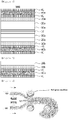
FIG. 1 is a schematic view showing a cross section of the lithium electrode according to a first preferred embodiment of the present invention. -
FIG. 2 is a schematic view showing a cross section of the lithium electrode according to a second preferred embodiment of the present invention. -
FIG. 3 is a schematic view showing a cross section of the lithium electrode according to a third preferred embodiment of the present invention. -
FIG. 4 is a schematic view showing a cross section of the lithium electrode according to a fourth preferred embodiment of the present invention. -
FIG. 5 is a schematic view showing a cross section of the lithium electrode according to a fifth preferred embodiment of the present invention. -
FIG. 6 is a schematic view showing a cross section of the lithium electrode according to a sixth preferred embodiment of the present invention. -
FIG. 7 is a schematic view showing the lithium electrode laminate before transfer to the current collector during the manufacturing process of the lithium electrode according to the present invention. -
FIG. 8 is a schematic view showing the manufacturing process of the lithium electrode according to Example 1. -
FIG. 9 is a photograph showing the lithium electrode manufactured in Example 1. -
FIG. 10 is a photograph showing the lithium electrode manufactured in Comparative Example 1. - Hereinafter, the present invention will be described in detail in order to facilitate understanding of the present invention.
- The terms and words used in the present specification and claims should not be construed as limited to ordinary or dictionary terms, and should be construed in a sense and concept consistent with the technical idea of the present invention, based on the principle that the inventor can properly define the concept of a term to describe his invention in the best way possible.
- Hereinafter, the structure of the lithium electrode according to the present invention will be described in detail with reference to the drawings.
- The present invention relates to a lithium electrode capable of increasing the energy density of a battery.
-
FIG. 1 is a schematic view showing a cross section of the lithium electrode according to a first preferred embodiment of the present invention. - Referring to
Figure 1 , thelithium electrode 100 may have lithium metal layers 10a and 10b formed on both sides of thecurrent collector 10 andprotective layers FIG. 1 shows an example where lithium metal layers 10a and 10b are formed on both sides of thecurrent collector 10, but the present invention is not limited thereto, and the lithium metal layer may be also formed on one side of the current collector. - In the present invention, the
current collector 10 may be a variety of current collectors selected from the group consisting of copper (Cu), aluminum (Al), nickel (Ni), titanium (Ti), sintered carbon and stainless steel (SUS). - The
current collector 10 may have a thickness of 1 to 10 µm, preferably 1 to 8 µm, more preferably 1 to 6 µm. If the thickness of thecurrent collector 10 is less than the above range, the durability of the electrode may be deteriorated. If the thickness of thecurrent collector 10 exceeds the above range, the thickness of the electrode may be thickened. - In the present invention, the lithium metal layers 10a and 10b are formed on both sides of the
current collector 10, and the lithium metal layers 10a and 10b are formed on both sides of thecurrent collector 10 by the transfer process, but not by deposition, which is carried out in accordance with a method as described below, and thus it is possible to form thin and uniform lithium metal layers 10a and 10b. - In addition, since the lithium metal layers 10a and 10b formed on both sides of the
current collector 10 are formed and then transferred by the process under the same condition, the two lithium metal layers 10a and 10b may have the same shape and physical properties. - The lithium metal layers 10a and 10b may each have a thickness of 1 to 50 µm, preferably 5 to 40 µm, more preferably 10 to 30 µm. If the thickness is less than the above range, the charging and discharging performance of the battery may be deteriorated. If the thickness is less than the above range, the thickness of the electrode may be increased.
- In a typical lithium secondary battery, since the amount of lithium contained in the positive electrode is all of the lithium, its capacity is limited. However, in the case of the battery comprising the lithium electrode according to the present invention as a negative electrode, the negative electrode as well as the positive electrode contains lithium, and lithium ions may be supplied from such lithium, so that an additional increase of capacity may be expected. If the thickness of the lithium metal layer in the lithium negative electrode is thick, the increase in capacity will be greater. However, considering the economic efficiency and handling property, the lithium metal layer having the thickness in the numerical range as described above is preferable.
- Meanwhile, when the lithium metal layer is used for irreversible compensation of the SiO coating layer as described below, the lithium metal layer may have a thickness of 1 to 10 µm. Since lithium is used only for the irreversible compensation of the SiO coating layer irrespective of the increase in the capacity of the battery, the thickness of the lithium metal layer does not need to be thick.
- In the present invention, the
protective layers lithium electrode 100 and during the driving process of thelithium electrode 100. - Therefore, the material for forming the
protective layers - The
protective layers - The thicknesses of the
protective layers protective layer lithium electrode 100 may be thickened. -
FIG. 2 is a schematic view showing a cross section of the lithium electrode according to a second preferred embodiment of the present invention. - Referring to
FIG. 2 , thelithium electrode 100 may havesubstrates protective layers FIG. 1 . - In the present invention, the
substrates protective layers substrates lithium electrode 100 is put into the battery manufacturing process and laminated with the separator and the positive electrode. Thelithium electrode 100 in a state of comprising thesubstrates lithium electrode 100 in a semifinished state. - The
substrates - The
substrates substrates -
FIG. 3 is a schematic view showing a cross section of the lithium electrode according to a third preferred embodiment of the present invention. - Referring to
FIG. 3 , therelease layer 41 may be formed on one side (not shown) or on both sides of thesubstrates lithium electrode 100 as shown inFIG. 2 . - In the present invention, the
release layer 41 may facilitate the delamination of thesubstrates lithium electrode 100 is put into a battery manufacturing process. - The
release layer 41 may comprise at least one selected from the group consisting of a silicone-based resin, a melamine-based resin and a fluorine-based resin. It may be preferable to use the silicone-based resin in terms of cost and commercialization. - The thickness of the
release layer 41 may be formed in a suitable thickness within a range that does not cause physical damage to theprotective layers substrates -
FIG. 4 is a schematic view showing a cross section of the lithium electrode according to a fourth preferred embodiment of the present invention. - Referring to
FIG. 4 , thelithium electrode 100 may further comprise SiO coating layers 50a and 50b formed between thecurrent collector 10 and thelithium metal layers FIG. 1 . - In the present invention, the SiO coating layers 50a and 50b may increase the capacity of the
lithium electrode 100. When only the SiO coating layers 50a and 50b are present, a large irreversible phenomenon may occur during the initial discharging, but it is possible to prevent the occurrence of a large irreversible phenomenon during the initial discharging and at the same time to increase the capacity of thelithium electrode 100 by manufacturing thelithium electrode 100 having the structure obtained by forming thelithium metal layers - The SiO coating layers 50a and 50b may be a mixed coating layer of SiO and graphite, and SiO and graphite may be mixed in a weight ratio of 1 : 1 to 1 : 9. If the weight ratio of graphite to SiO is less than 1 : 1, the capacity increase effect of the
lithium electrode 100 may be insignificant. If the weight ratio is more than 1 : 9, an irreversible phenomenon may occur. - The SiO coating layers 50a and 50b may each have a thickness of 60 to 120 µm, preferably 65 to 100 µm, and more preferably 70 to 90 µm. If the thickness is less than the above range, the capacity of the electrode may be lowered. If the thickness exceeds the above range, irreversible compensation of SiO by lithium may not be completely achieved.
-
FIG. 5 is a schematic view showing a cross section of the lithium electrode according to a fifth preferred embodiment of the present invention. - Referring to
FIG. 5 , thelithium electrode 100 may have thesubstrates protective layers FIG. 4 . - The roles, the constituent materials, and the thicknesses of the
substrates FIG. 2 . -
FIG. 6 is a schematic view showing a cross section of the lithium electrode according to a sixth preferred embodiment of the present invention. - Referring to
FIG. 6 , therelease layer 41 may be formed on one side (not shown) or on both sides of thesubstrates lithium electrode 100 as shown inFIG. 5 . - The roles, the constituent materials, and the thicknesses of the
release layer 41 are the same as those described inFIG. 3 . - The present invention also relates to a lithium electrode comprising a current collector; lithiated SiO coating layers formed on both sides of the current collector; and protective layers formed respectively on the lithiated SiO coating layers.
- In the lithium electrode, the type and shape of the current collector, protective layer, release layer and substrate are the same as described above.
- In the present invention, the lithiated SiO coating layer means that after the SiO coating layer is formed between the current collector and the lithium metal layer, lithium is melted into the SiO coating layer by solid-solid reaction to form a lithiated SiO coating layer. At this time, the lithium metal layer is completely disappeared.
- The lithiated SiO coating layer may have a thickness of 60 to 120 µm, preferably 65 to 100 µm, more preferably 70 to 90 µm. If the thickness is less than the above range, the capacity of the electrode may be lowered. If the thickness exceeds the above range, irreversible compensation of SiO by lithium may not be completely achieved.
- The present invention also relates to a method of manufacturing a lithium electrode capable of increasing the energy density of a battery, comprising the steps of: (S1) forming a protective layer by coating a polymer for protecting lithium metal on the substrate; (S2) depositing lithium metal on the protective layer to form a lithium metal layer; and (S3) transferring the lithium metal layer to at least one side of the current collector.
-
FIG. 7 is a schematic view showing the lithium electrode laminate before transfer to the current collector during the manufacturing process of the lithium electrode according to the present invention. - Referring to
FIG. 7 , the lithium electrode is formed by sequentially formingprotective layers lithium metal layers substrates - Hereinafter, the present invention will be described in more detail for each step.
- In step (S1), a polymer for protecting lithium metal may be coated on the substrate to form a protective layer for protecting lithium metal.
- The substrate may be a material having characteristics that may withstand the process conditions such as high temperature in the step of depositing lithium metal, and may prevent the reverse delamination problem in which the lithium metal layer is transferred onto the substrate rather than the current collector during the winding process for transferring the deposited lithium metal layer to the current collector.
- For example, the substrate may be at least one selected from the group consisting of polyethylene terephthalate (PET), polyimide (PI), poly(methylmethacrylate) (PMMA), cellulose tri-acetate (TAC), plypropylene, polyethylene and polycarbonate.
- In addition, the substrate may have a release layer formed on at least one side thereof, preferably release layers formed on both sides thereof. The problem of inverse delamination in which the lithium metal layer is transferred onto the substrate rather than the current collector may be prevented by the release layer during the winding process for transferring the deposited lithium metal layer to the current collector, and also the substrate may be easily separated after the lithium metal layer is transferred onto the current collector.
- The release layer may comprise at least one selected from the group consisting of a silicone-based resin, a melamine-based resin and a fluorine-based resin.
- The release layer may be formed by a coating method. For example, the coating method may be, but is not limited to, a method selected from the group consisting of dip coating, spray coating, spin coating, die coating, and roll coating, but a variety of coating methods that may be used to form a coating layer in the art can be used.
- In step (S2), lithium metal may be deposited on the protective layer to form a lithium metal layer.
- In the present invention, the protective layer may protect the lithium metal from external environment such as moisture or outside air to minimize the formation of oxide film (native layer) on the surface in a series of processes for manufacturing the lithium electrode.
- Therefore, the material for forming the protective layer should have high moisture barrier properties, stability to the electrolyte, high electrolyte wettability, and excellent oxidation/reduction stability.
- For example, the protective layer may comprise at least one selected from the group consisting of poly vinylidene fluoride (PVDF), poly vinylidene fluoride-hexafluoroethylne copolymer (PVDF-HFP copolymer), cyclo olefin polymer, cyclo olefin copolymer and styrene butadiene rubber-carboxymethyl cellulose (SBR-CMC).
- The thickness of the protective layer may be 0.1 µm to 1.0 µm, preferably 0.3 µm to 0.8 µm, more preferably 0.4 µm to 0.6 µm. If the thickness of the protective layer is less than the above range, the function of protecting the lithium metal from moisture or outside air may be deteriorated. If the thickness exceeds the above range, the lithium electrode may be thickened.
- The coating solution for forming the protective layer may be prepared by dissolving the polymer as described above in a solvent. At this time, the concentration of the coating solution may be 1% to 20%, preferably 3% to 10%, more preferably 4% to 8%. If the concentration of the coating solution is less than the above range, the viscosity is very low and thus the coating process is difficult to proceed. If the concentration of the coating solution exceeds the above range, the viscosity may be high and it may be difficult to form a coating layer with a desired coating thickness. At this time, examples of the solvent for forming the coating solution may be at least one selected from the group consisting of N-methyl-2-pyrrolidone (NMP), dimethyl formamide (DMF), dimethyl acetamide (DMAc), tetramethyl urea, dimethyl sulfoxide (DMSO) and triethyl phosphate. In particular, when NMP is used, the solubility of the polymer for forming the protective layer is high as described above, and it may be advantageous to form the protective layer by the coating process.
- In addition, examples of the coating method for forming the protective layer may be, but is not limited to, a method selected from the group consisting of dip coating, spray coating, spin coating, die coating, roll coating, Slot-die coating, Bar coating, Gravure coating, Comma coating, Curtain coating and Micro-Gravure coating, but a variety of coating methods that may be used to form a coating layer in the art can be used.
- In the present invention, the lithium metal layer formed on the protective layer by deposition may have a thickness of 1 to 50 µm, preferably 5 to 40 µm, more preferably 10 to 30 µm. The thickness of the lithium metal layer may be varied depending on the application. When only lithium metal is used as the electrode material, for example, as a negative electrode material, the thickness of the lithium metal layer is sufficient if it is in the range of 20 to 25 µm, but when lithium metal is used as a material to compensate for the irreversible phenomenon occurring in the negative electrode of the silicon oxide material, the thickness of the lithium metal layer may be about 1 to 12 µm. If the thickness of the lithium metal layer is less than the above range, the capacity and life characteristics of the battery may be deteriorated. If the thickness of the lithium metal layer exceeds the above range, the thickness of the lithium electrode to be manufactured may be thickened, which may be detrimental to commercialization.
- In the present invention, examples of the deposition method for depositing the lithium metal may be, but is not limited to, a method selected from the group consisting of evaporation deposition, chemical vapor deposition (CVD), and physical vapor deposition, but a variety of deposition methods that is used in the art can be used.
- In step (S3), the lithium metal layer may be transferred to a current collector. At this time, after winding the structure in which the substrate, the protective layer and the lithium metal layer are sequentially stacked, the transfer may be performed such that the lithium metal layer is transferred onto the current collector using a device such as a roll press.
- In the present invention, the current collector may be one selected from the group consisting of copper, aluminum, nickel, titanium, sintered carbon, and stainless steel.
- When a lithium metal is directly deposited on a current collector, in particular, when lithium metal is directly deposited on a copper current collector, there is a problem that the copper current collector is easily broken. However, for the present invention, since the lithium metal layer is formed and then the lithium metal layer itself is transferred to the current collector to manufacture the lithium electrode, the lithium electrode may be manufactured using various current collectors.
- In addition, both sides of the current collector may be coated with an SiO coating layer. The role, constituent material and thickness of the SiO coating layer are as described above.
- The SiO coating layer may be formed by dissolving a mixture of SiO and graphite in an organic solvent such as ethanol by 0.5 to 2 M concentration to form a coating solution and then coating the coating solution on at least one side of the current collector.
- The SiO coating layer may be formed by a coating method. For example, the coating method may be, but is not limited to, a method selected from the group consisting of dip coating, spray coating, spin coating, die coating, and roll coating, but a variety of coating methods that may be used to form a coating layer in the art can be used.
- Meanwhile, after the SiO coating layer is formed, lithium is melted into the SiO coating layer by solid-solid reaction to form a lithiated SiO coating layer, and the lithium metal layer is completely disappeared.
- According to the manufacturing method of the lithium electrode as described above, a method of depositing lithium metal on a lithium metal protective layer and transferring it to a current collector is used in order to manufacture the lithium electrode, and a lithium electrode in which a current collector, a lithium metal layer, and a protective layer are sequentially stacked may be manufactured.
- In addition, the lithium electrode with a thin and uniform thickness may be manufactured by protecting the lithium metal from exposure to external environments such as moisture or outside air during the manufacturing process by the protective layer and thus minimizing the formation of an oxide layer (native layer) on the surface of lithium metal.
- In addition, since a method of forming a lithium metal layer on the current collector by transfer without depositing lithium metal directly on the current collector is used, it is possible to compensate for the problem of the current collector which is liable to break during the deposition process and thus the lithium electrode may be manufactured using various kind of current collectors.
- The present invention relates to a lithium secondary battery comprising the lithium electrode as described above.
- In the lithium secondary battery according to the present invention, the lithium electrode may be used as a negative electrode, and the lithium secondary battery may comprise a lithium negative electrode, an electrolyte solution, a separator, and a positive electrode. As the electrolyte solution, the separator, and the positive electrode, those conventionally used in the art can be widely used.
- For the positive electrode, a lithium-containing transition metal oxide may be preferably used as the positive electrode active material. For example, the positive electrode active material may be any one selected from the group consisting of LixCoO2(0.5<x<1.3), LixNiO2(0.5<x<1.3), LixMnO2(0.5<x<1.3), LixMn2O4(0.5<x<1.3), Lix(NiaCobMnc)O2(0.5<x<1. 3, 0<a<1, 0<b<1, 0<c<1, a+b+c=1), LixNi1-yCoyO2(0.5<x<1.3, 0<y<1), LixCo1-yMnyO2(0.5<x<1.3, 0≤y<1), LixNi1-yMnyO2(0.5<x<1. 3, O≤y<1), Lix(NiaCobMnc)O4(0.5<x<1.3, 0<a<2, 0<b<2, 0<c<2, a+b+c=2), LixMn2-zNizO4(0.5<x<1.3, 0<z<2), LixMn2-zCozO4(0.5<x<1.3, 0<z<2), LixCoPO4(0.5<x<1.3) and LixFePO4(0.5<x<1.3), or a mixture of two or more thereof. The lithium-containing transition metal oxide may be coated with a metal such as aluminum (Al) or a metal oxide. In addition to the lithium-containing transition metal oxide, sulfide, selenide, halide and the like may also be used.
- For the separator, in order to improve the mechanical strength and to improve the safety of the lithium secondary battery, the porous polymer substrate may further comprise, on at least one side thereof, a porous coating layer containing inorganic particles and a polymer binder. In this case, the inorganic particles are not particularly limited as long as they are electrochemically stable. That is, the inorganic particles that may be used in the present invention are not particularly limited as long as oxidation and/or reduction reaction does not occur in a range of the applied operating voltage of the lithium secondary battery (for example, 0 to 5 V based on Li/Li+). Particularly, when inorganic particles having a high dielectric constant are used as the inorganic particles, such inorganic particles may contribute to an increase in the dissociation of the electrolyte salts in the liquid electrolyte, such as lithium salts, thereby improving the ion conductivity of the electrolyte.
- In that case, the polymer binder may be, but is not limited to, any one selected from the group consisting of polyvinylidene fluoride-co-hexafluoropropylene (PVDF-HFP), polyvinylidene fluoride-co-chlorotrifluoroethylene, polyvinylidene fluoride-co-trichloroethylene, polymethylmethacrylate, polybutylacrylate, polyacrylonitrile, polyvinylpyrrolidone, polyvinylacetate, polyethylene-co-vinyl acetate, polyethylene, polyethylene oxide, polyarylate, cellulose acetate, cellulose acetate butyrate, cellulose acetate propionate, cyanoethylpullulan, cyanoethylpolyvinylalcohol, cyanoethylcellulose, cyanoethylsucrose, pullulan and carboxyl methyl cellulose, or a mixture of two or more thereof.
- In the porous coating layer, the polymer binder is coated on part or all of the surface of the inorganic particles, the inorganic particles are connected and fixed to each other by the polymer binder in an adhered state, an interstitial volume is formed between the inorganic particles, and the interstitial volume between the inorganic particles is preferably an empty space to form pores. These void spaces become pores of the porous coating layer, and it is preferable that these pores are equal to or smaller than the average particle diameter of the inorganic particles.
- In the present invention, the electrolyte solution may comprise a non-aqueous solvent and an electrolyte salt.
- The non-aqueous solvent is not particularly limited as long as it is used as a non-aqueous solvent for a non-aqueous electrolyte solution. A cyclic carbonate, a linear carbonate, a lactone, an ether, an ester, or a ketone may be used.
- Examples of the cyclic carbonate comprise ethylene carbonate (EC), propylene carbonate (PC), butylene carbonate (BC) and the like, and examples of the linear carbonate comprise diethyl carbonate (DEC), dimethyl carbonate (DMC), dipropyl carbonate (DPC), ethylmethylcarbonate (EMC), methyl propyl carbonate (MPC) and the like. Examples of the lactone comprise gamma butyrolactone (GBL), and examples of the ether comprise dibutyl ether, tetrahydrofuran, 2-methyl tetrahydrofuran, 1,4-dioxane, 1,2-dimethoxyethane and the like. Also, examples of the esters comprise n-methyl acetate, n-ethyl acetate, methyl propionate, methyl pivalate and the like. The ketone comprises poly methyl vinyl ketone. These non-aqueous solvents may be used alone or in admixture of two or more.
- The electrolyte salt is not particularly limited as long as it is usually used as an electrolyte salt for a non-aqueous electrolyte solution. A non-limiting example of an electrolyte salt is a salt of the structure like A+B- wherein A+ comprises ions consisting of alkali metal cations such as Li+, Na+, and K+, or combinations thereof and B- comprises ions consisting of anions such as PF6 -, BF4 -, Cl-, Br-, I-, ClO4 -, ASF6 -, CH3CO2 -, CF3SO3 -, N(CF3SO2)2 -, and C(CF2SO2)3 - or combinations thereof. In particular, lithium salts are preferred. These electrolyte salts may be used alone or in combination of two or more.
- The injection of the non-aqueous electrolyte solution may be performed at an appropriate stage depending on the manufacturing process and the required properties of the final product during the manufacturing process of the lithium secondary battery. That is, the injection may be applied before the assembly of the lithium secondary battery or at the final stage of the assembly of the lithium secondary battery.
- The outer shape of the lithium secondary battery according to an embodiment of the present invention comprising the electrode assembly thus obtained is not particularly limited, but may be a cylindrical shape using a can, a square shape, a pouch shape, a coin shape, or the like.
- In particular, the lithium electrode according to the present invention has a thin thickness and excellent thickness uniformity, and thus may significantly improve the energy density when applied to a lithium secondary battery.
- Hereinafter, preferred examples of the present invention will be described in order to facilitate understanding of the present invention. It will be apparent to those skilled in the art, however, that the following examples are illustrative of the present invention and that various changes and modifications may be made within the scope and spirit of the present invention. Such variations and modifications are within the scope of the appended claims.
- A release PET film (SKC Haas, RX12G 50 µm) having a release layer on both sides was prepared as a substrate.
- A PVDF-HFP coating solution was prepared as a coating solution for forming a protective layer for protecting lithium metal on one side of the substrate. The PVDF-HFP coating solution was prepared by dissolving PVDF-HFP (Arkema, LBG Grade) in NMP solvent to be a 5% solution.
- The PVDF-HFP coating solution was coated on one side of the release PET film by 0.2 µm in thickness using a Micro-Gravure coater to form a PVDF-HFP protective layer.
- Lithium metal was deposited on the protective layer by evaporation deposition at a temperature of 600 °C to form a lithium metal layer having a thickness of 20 µm, and a structure, in which the above-mentioned release PET film, the PVDF-HFP protective layer and the lithium metal layer were sequentially stacked, was wound at a speed of 1 m/min. Two stacked structures thus obtained were prepared.
- Thereafter, the lithium metal layer was transferred to both sides of the Cu current collector using a roll press machine (Calendering machine CLP-1015, CIS), and thus a laminated lithium electrode obtained by sequentially forming the lithium metal layer and the PVDF-HFP protective layer on both sides of the Cu current collector was prepared.
-
FIG. 8 is a schematic view showing the manufacturing process of the lithium electrode according to Example 1. - Referring to
FIG. 8 , the lithium electrode may be manufactured by transferring the twostacked structures 60 prepared as described above to both sides of thecurrent collector 10. - A PVDF protective layer was formed in the same manner as in Example 1 except that PVDF instead of PVDF-HFP as a polymer for forming a protective layer was used.
- A lithium electrode was manufactured in the same manner as in Example 1 except that a current collector having SiO coating layers on both sides thereof was used.
- At this time, in order to form the SiO coating layer, the mixture of SiO and graphite in a weight ratio of 1: 1 was dissolved in ethanol solvent to form a coating solution with 1 M concentration.
- The coating solution was coated on both sides of the current collector by 80 µm in thickness using a slot-die coater to form SiO coating layers.
- Lithium metal was directly deposited on the Cu current collector to form a lithium metal layer, and then a PVDF-HFP coating solution was coated on the lithium metal layer to form a lithium electrode. At this time, the deposition process was performed by evaporation deposition at a temperature of 600 °C to form a lithium metal layer having a thickness of 12 µm, and the PVDF-HFP coating solution was prepared by dissolving PVDF-HFP (Arkema, LBG Grade) in NMP solvent to be a 5% solution and then a PVDF-HFP protective layer was prepared on the lithium metal layer by spin coating.
-
FIG. 9 is a photograph showing the lithium electrode manufactured in Example 1, andFIG. 10 is a photograph showing the lithium electrode manufactured in Comparative Example 1. - Referring to
FIG. 9 , it was confirmed that a normal lithium electrode is manufactured in Example 1 by transfer. - On the other hand, referring to
FIG. 10 , it was confirmed in the case of Comparative Example 1 that wrinkle phenomenon occurs due to direct deposition process on the Cu current collector. It can be seen that the wrinkle phenomenon is a folding and tearing phenomenon and this phenomenon appears by direct deposition process on the Cu current collector having a thin thickness. - Although the present invention has been described with reference to the limited examples and drawings, it is to be understood that the present invention is not limited thereto and that various modifications and variations are possible within the scope of the claims to be described below and the technical idea of the present invention.
-
- 10: Current collector
- 20a, 20b: Lithium metal layer
- 30a, 30b: Protective layer
- 40a, 40b: Substrate
- 41: Release layer
- 50a, 50b: SiO coating layer
- 60: Stacked structure
Claims (13)
- A lithium electrode comprising
a current collector;
a lithium metal layer on at least one side of the current collector; and
a protective layer on the lithium metal layer. - The lithium electrode according to claim 1, further comprising a SiO coating layer between the current collector and the lithium metal layer.
- The lithium electrode according to claim 2, wherein the SiO coating layer is a mixed coating layer comprising SiO and graphite.
- The lithium electrode according to claim 3, wherein the SiO and graphite are mixed in a weight ratio of 1 : 1 to 1 : 9.
- The lithium electrode according to claim 1, wherein the current collector is selected from the group consisting of copper; stainless steel; aluminum; nickel; titanium; sintered carbon; stainless steel whose surface is treated with carbon, nickel, titanium, or silver; and aluminum-cadmium alloy.
- The lithium electrode according to claim 1, wherein the lithium metal layer has a thickness of 1 to 50 µm.
- The lithium electrode according to claim 1, wherein the protective layer comprises at least one selected from the group consisting of poly vinylidene fluoride (PVDF), poly vinylidene fluoride-hexafluoroethylene copolymer (PVDF-HFP copolymer), cyclo olefin polymer, cyclo olefin copolymer and styrene butadiene rubber-carboxymethyl cellulose (SBR-CMC).
- The lithium electrode according to claim 1, further comprising a substrate on the protective layer.
- The lithium electrode according to claim 8, further comprising a release layer on at least one side of the substrate.
- The lithium electrode according to claim 9, wherein the release layer comprises at least one selected from the group consisting of a silicone-based resin, a melamine-based resin and a fluorine-based resin.
- The lithium electrode according to claim 8, wherein the substrate comprises at least one selected from the group consisting of polyethylene terephthalate (PET), polyimide (PI), poly(methylmethacrylate) (PMMA), cellulose tri-acetate (TAC), polypropylene, polyethylene and polycarbonate.
- A lithium electrode comprising
a current collector;
a lithiated SiO coating layer on at least one side of the current collector; and
a protective layer on the lithiated SiO coating layer. - A lithium secondary battery comprising the lithium electrode according to claim 1.
Applications Claiming Priority (2)
| Application Number | Priority Date | Filing Date | Title |
|---|---|---|---|
| KR20170133772 | 2017-10-16 | ||
| PCT/KR2018/012151 WO2019078571A2 (en) | 2017-10-16 | 2018-10-16 | Lithium electrode and lithium secondary battery comprising same |
Publications (2)
| Publication Number | Publication Date |
|---|---|
| EP3667774A2 true EP3667774A2 (en) | 2020-06-17 |
| EP3667774A4 EP3667774A4 (en) | 2021-03-17 |
Family
ID=66282392
Family Applications (1)
| Application Number | Title | Priority Date | Filing Date |
|---|---|---|---|
| EP18868689.3A Pending EP3667774A4 (en) | 2017-10-16 | 2018-10-16 | Lithium electrode and lithium secondary battery comprising same |
Country Status (5)
| Country | Link |
|---|---|
| US (1) | US11430977B2 (en) |
| EP (1) | EP3667774A4 (en) |
| JP (1) | JP7150012B2 (en) |
| KR (1) | KR102305482B1 (en) |
| CN (1) | CN111201645B (en) |
Cited By (1)
| Publication number | Priority date | Publication date | Assignee | Title |
|---|---|---|---|---|
| EP3667775A4 (en) * | 2017-12-04 | 2020-11-18 | LG Chem, Ltd. | Lithium electrode, method for manufacturing same, and lithium secondary battery comprising same |
Families Citing this family (2)
| Publication number | Priority date | Publication date | Assignee | Title |
|---|---|---|---|---|
| CN111725486A (en) * | 2020-07-01 | 2020-09-29 | 昆山宝创新能源科技有限公司 | Lithium metal negative electrode and preparation method and application thereof |
| WO2023150882A1 (en) * | 2022-02-11 | 2023-08-17 | Li-Metal Corp. | Processing pvd-deposited anode assemblies |
Family Cites Families (39)
| Publication number | Priority date | Publication date | Assignee | Title |
|---|---|---|---|---|
| JPS605938B2 (en) | 1979-01-27 | 1985-02-14 | 三菱製紙株式会社 | Method for manufacturing organic electrophotographic photoreceptor |
| ID21480A (en) * | 1997-05-30 | 1999-06-17 | Matsushita Electric Ind Co Ltd | SECONDARY ELECTROLITE CELLS NOT WATER |
| US6214061B1 (en) | 1998-05-01 | 2001-04-10 | Polyplus Battery Company, Inc. | Method for forming encapsulated lithium electrodes having glass protective layers |
| US7247408B2 (en) | 1999-11-23 | 2007-07-24 | Sion Power Corporation | Lithium anodes for electrochemical cells |
| JP4997674B2 (en) * | 2001-09-03 | 2012-08-08 | 日本電気株式会社 | Negative electrode for secondary battery and secondary battery |
| US6991662B2 (en) * | 2001-09-10 | 2006-01-31 | Polyplus Battery Company | Encapsulated alloy electrodes |
| JP3982230B2 (en) * | 2001-10-18 | 2007-09-26 | 日本電気株式会社 | Secondary battery negative electrode and secondary battery using the same |
| US6911280B1 (en) | 2001-12-21 | 2005-06-28 | Polyplus Battery Company | Chemical protection of a lithium surface |
| KR100497231B1 (en) | 2003-07-08 | 2005-06-23 | 삼성에스디아이 주식회사 | Negative electrode for lithium secondary battery, method of preparing same, and lithium secondary battery comprising same |
| KR100496306B1 (en) | 2003-08-19 | 2005-06-17 | 삼성에스디아이 주식회사 | Method for preparing of lithium metal anode |
| JP5119584B2 (en) | 2005-10-11 | 2013-01-16 | パナソニック株式会社 | Nonaqueous electrolyte secondary battery and method for producing the negative electrode |
| JP5476612B2 (en) * | 2006-03-09 | 2014-04-23 | パナソニック株式会社 | Method for producing transfer film and method for producing electrode plate for electrochemical device |
| JP5151188B2 (en) | 2006-03-09 | 2013-02-27 | パナソニック株式会社 | TRANSFER FILM, ELECTRODE ELECTRODE FOR ELECTROCHEMICAL DEVICE FORMED USING THE SAME, AND LITHIUM SECONDARY BATTERY |
| JP4957680B2 (en) * | 2008-08-26 | 2012-06-20 | ソニー株式会社 | Electrode with porous protective film layer for non-aqueous electrolyte secondary battery, and non-aqueous electrolyte secondary battery |
| TWI365562B (en) | 2008-10-03 | 2012-06-01 | Ind Tech Res Inst | Positive electrode and method for manufacturing the same and lithium battery utilizing the same |
| US8703333B2 (en) | 2009-02-27 | 2014-04-22 | Toyota Motor Engineering & Manufacturing North America, Inc. | Electrode compositions and processes |
| JP5509475B2 (en) * | 2009-05-26 | 2014-06-04 | エルジー ケム. エルティーディ. | Lithium secondary battery and method for producing lithium secondary battery |
| KR101085359B1 (en) | 2009-08-13 | 2011-11-21 | 비나텍주식회사 | Lithium metal capacitor of Energy storage device and manufacturing method therefor |
| EP2721665B1 (en) * | 2011-06-17 | 2021-10-27 | Sion Power Corporation | Plating technique for electrode |
| JP2015046220A (en) | 2011-12-29 | 2015-03-12 | パナソニック株式会社 | Nonaqueous electrolyte secondary battery |
| JP2014044921A (en) * | 2012-08-29 | 2014-03-13 | Hitachi Ltd | Lithium ion secondary battery, and method for manufacturing the same |
| CN105122501B (en) | 2013-03-15 | 2019-02-19 | 锡安能量公司 | Protected electrode structure |
| US20140272594A1 (en) * | 2013-03-15 | 2014-09-18 | Sion Power Corporation | Protective structures for electrodes |
| JP2014205731A (en) | 2013-04-10 | 2014-10-30 | 富士フイルム株式会社 | Polyethylene terephthalate film and surface treatment method |
| CA2820468A1 (en) * | 2013-06-21 | 2014-12-21 | Hydro-Quebec | Anode including a lithium alloy for high energy batteries |
| CN103560162B (en) | 2013-11-20 | 2017-02-08 | 无锡中洁能源技术有限公司 | Solar cell back board and manufacturing method thereof |
| CN103560164A (en) | 2013-11-20 | 2014-02-05 | 无锡中洁能源技术有限公司 | Fluorine-containing radiating type solar cell backboard |
| KR101575455B1 (en) | 2014-02-27 | 2015-12-07 | 한국과학기술원 | Composite protecting layer for lithium oxygen battery and lithium oxygen batter comprising the same |
| CN104617328B (en) | 2014-07-10 | 2017-05-31 | 天津东皋膜技术有限公司 | A kind of long-life lithium rechargeable battery and its manufacture method |
| KR20160037488A (en) | 2014-09-29 | 2016-04-06 | 주식회사 엘지화학 | Cathode unit, manufacturing method thereof and removing method of protection film |
| KR101771292B1 (en) * | 2014-09-29 | 2017-08-24 | 주식회사 엘지화학 | Cathode unit covered with passivation layer and forming method of passivation layer for Li metal |
| KR101755121B1 (en) | 2014-10-31 | 2017-07-06 | 주식회사 엘지화학 | Lithium metal electrode for lithium secondary battery with safe protective layer and lithium secondary battery comprising the same |
| KR102475886B1 (en) | 2015-06-25 | 2022-12-08 | 삼성전자주식회사 | Negative electrode for lithium metal battery and lithium metal battery including the same |
| EP3136475B1 (en) | 2015-08-31 | 2021-09-22 | Samsung Electronics Co., Ltd. | Lithium metal battery |
| KR102618538B1 (en) | 2015-08-31 | 2023-12-28 | 삼성전자주식회사 | Lithium metal battery including lithium metal anode, method of protecting the lithium metal anode, and protective layer prepared according to the method |
| KR101990609B1 (en) * | 2015-09-24 | 2019-06-18 | 주식회사 엘지화학 | Lithium electrode and lithium secondary battery employing thereof |
| CN107534128B (en) | 2015-12-17 | 2020-10-20 | 株式会社Lg化学 | Negative electrode for lithium secondary battery and lithium secondary battery comprising same |
| KR20180100706A (en) | 2016-01-28 | 2018-09-11 | 어플라이드 머티어리얼스, 인코포레이티드 | Integrated Lithium Deposition with Protective Layer Tools |
| KR101829172B1 (en) * | 2017-07-14 | 2018-03-29 | 주식회사 엘지화학 | Cathode unit, manufacturing method thereof and removing method of protection film |
-
2018
- 2018-10-16 CN CN201880066284.0A patent/CN111201645B/en active Active
- 2018-10-16 JP JP2020517357A patent/JP7150012B2/en active Active
- 2018-10-16 EP EP18868689.3A patent/EP3667774A4/en active Pending
- 2018-10-16 US US16/646,125 patent/US11430977B2/en active Active
- 2018-10-16 KR KR1020180122935A patent/KR102305482B1/en active IP Right Grant
Cited By (3)
| Publication number | Priority date | Publication date | Assignee | Title |
|---|---|---|---|---|
| EP3667775A4 (en) * | 2017-12-04 | 2020-11-18 | LG Chem, Ltd. | Lithium electrode, method for manufacturing same, and lithium secondary battery comprising same |
| US11532810B2 (en) | 2017-12-04 | 2022-12-20 | Lg Energy Solution, Ltd. | Lithium electrode, method for manufacturing same, and lithium secondary battery comprising same |
| US11735717B2 (en) | 2017-12-04 | 2023-08-22 | Lg Energy Solution, Ltd. | Lithium electrode, method for manufacturing same, and lithium secondary battery comprising same |
Also Published As
| Publication number | Publication date |
|---|---|
| JP2020535607A (en) | 2020-12-03 |
| KR20190042471A (en) | 2019-04-24 |
| EP3667774A4 (en) | 2021-03-17 |
| CN111201645B (en) | 2023-07-25 |
| CN111201645A (en) | 2020-05-26 |
| US20200274142A1 (en) | 2020-08-27 |
| JP7150012B2 (en) | 2022-10-07 |
| KR102305482B1 (en) | 2021-09-27 |
| US11430977B2 (en) | 2022-08-30 |
Similar Documents
| Publication | Publication Date | Title |
|---|---|---|
| US9368777B2 (en) | Electrochemical device with improved cycle characteristics | |
| EP2690696B1 (en) | Electrode assembly and method for manufacturing same | |
| EP2784843B1 (en) | Slurry with improved dispersibility and use therefor | |
| US20080311479A1 (en) | Electrode With Enhanced Safety and Electrochemical Device Having the Same | |
| JP7048846B2 (en) | Lithium electrode, this manufacturing method and a lithium secondary battery containing it | |
| KR102225305B1 (en) | Method of Manufacturing Separator Having Inorganic Coating Layer Using Phase Separation | |
| US11430977B2 (en) | Lithium electrode and lithium secondary battery comprising same | |
| KR102148507B1 (en) | Lithium Metal Electrode and Method for Preparing the Same | |
| US20230170579A1 (en) | Separator for secondary battery including adhesive layer and method for manufacturing the same | |
| KR20190016594A (en) | Low melting temperature metal purification and deposition | |
| CN106415913B (en) | Secondary battery and spacer used therefor | |
| US20170179520A1 (en) | Secondary battery | |
| CN111213256B (en) | Separator for electrochemical device, method for manufacturing same, and electrochemical device comprising same | |
| EP4027445A1 (en) | Separator, lithium secondary battery including separator, and method for manufacturing same | |
| EP4033595A1 (en) | Separation membrane for electrochemical device, electrochemical device comprising same separation membrane, and method for manufacturing same separation membrane | |
| KR102448076B1 (en) | Method for Preparing Lithium Metal Electrode | |
| KR102543245B1 (en) | Lithium Metal Electrode, Method for Preparing the Same and Lithium Secondary Battery | |
| KR20090103836A (en) | Anode and secondary battery |
Legal Events
| Date | Code | Title | Description |
|---|---|---|---|
| STAA | Information on the status of an ep patent application or granted ep patent |
Free format text: STATUS: THE INTERNATIONAL PUBLICATION HAS BEEN MADE |
|
| PUAI | Public reference made under article 153(3) epc to a published international application that has entered the european phase |
Free format text: ORIGINAL CODE: 0009012 |
|
| STAA | Information on the status of an ep patent application or granted ep patent |
Free format text: STATUS: REQUEST FOR EXAMINATION WAS MADE |
|
| 17P | Request for examination filed |
Effective date: 20200309 |
|
| AK | Designated contracting states |
Kind code of ref document: A2 Designated state(s): AL AT BE BG CH CY CZ DE DK EE ES FI FR GB GR HR HU IE IS IT LI LT LU LV MC MK MT NL NO PL PT RO RS SE SI SK SM TR |
|
| AX | Request for extension of the european patent |
Extension state: BA ME |
|
| RIC1 | Information provided on ipc code assigned before grant |
Ipc: H01M 10/052 20100101ALI20201008BHEP Ipc: H01M 4/134 20100101AFI20201008BHEP Ipc: H01M 4/66 20060101ALI20201008BHEP |
|
| DAV | Request for validation of the european patent (deleted) | ||
| DAX | Request for extension of the european patent (deleted) | ||
| A4 | Supplementary search report drawn up and despatched |
Effective date: 20210212 |
|
| RIC1 | Information provided on ipc code assigned before grant |
Ipc: H01M 4/66 20060101ALI20210208BHEP Ipc: H01M 10/052 20100101ALI20210208BHEP Ipc: H01M 4/134 20100101AFI20210208BHEP |
|
| RAP1 | Party data changed (applicant data changed or rights of an application transferred) |
Owner name: LG ENERGY SOLUTION LTD. |
|
| RAP3 | Party data changed (applicant data changed or rights of an application transferred) |
Owner name: LG ENERGY SOLUTION, LTD. |
|
| STAA | Information on the status of an ep patent application or granted ep patent |
Free format text: STATUS: EXAMINATION IS IN PROGRESS |
|
| 17Q | First examination report despatched |
Effective date: 20231016 |