EP3667399A1 - Diffraktiver strahlaufweiter - Google Patents
Diffraktiver strahlaufweiter Download PDFInfo
- Publication number
- EP3667399A1 EP3667399A1 EP20154070.5A EP20154070A EP3667399A1 EP 3667399 A1 EP3667399 A1 EP 3667399A1 EP 20154070 A EP20154070 A EP 20154070A EP 3667399 A1 EP3667399 A1 EP 3667399A1
- Authority
- EP
- European Patent Office
- Prior art keywords
- coupled
- grating
- original
- deflecting
- restoring
- Prior art date
- Legal status (The legal status is an assumption and is not a legal conclusion. Google has not performed a legal analysis and makes no representation as to the accuracy of the status listed.)
- Pending
Links
- 230000001902 propagating effect Effects 0.000 claims abstract description 16
- 238000010168 coupling process Methods 0.000 claims abstract description 10
- 238000005859 coupling reaction Methods 0.000 claims abstract description 10
- 239000000758 substrate Substances 0.000 claims description 55
- 238000000034 method Methods 0.000 claims description 7
- 230000003287 optical effect Effects 0.000 description 15
- 238000003384 imaging method Methods 0.000 description 13
- 230000008878 coupling Effects 0.000 description 4
- 230000003993 interaction Effects 0.000 description 3
- 210000001747 pupil Anatomy 0.000 description 2
- 230000003190 augmentative effect Effects 0.000 description 1
- 230000015572 biosynthetic process Effects 0.000 description 1
- 230000008859 change Effects 0.000 description 1
- 230000009365 direct transmission Effects 0.000 description 1
- 210000005069 ears Anatomy 0.000 description 1
- 238000004049 embossing Methods 0.000 description 1
- 239000004973 liquid crystal related substance Substances 0.000 description 1
- 238000012986 modification Methods 0.000 description 1
- 230000004048 modification Effects 0.000 description 1
- 238000000465 moulding Methods 0.000 description 1
- 230000000737 periodic effect Effects 0.000 description 1
Images


Classifications
-
- G—PHYSICS
- G02—OPTICS
- G02B—OPTICAL ELEMENTS, SYSTEMS OR APPARATUS
- G02B5/00—Optical elements other than lenses
- G02B5/18—Diffraction gratings
- G02B5/1814—Diffraction gratings structurally combined with one or more further optical elements, e.g. lenses, mirrors, prisms or other diffraction gratings
-
- G—PHYSICS
- G02—OPTICS
- G02B—OPTICAL ELEMENTS, SYSTEMS OR APPARATUS
- G02B27/00—Optical systems or apparatus not provided for by any of the groups G02B1/00 - G02B26/00, G02B30/00
- G02B27/0081—Optical systems or apparatus not provided for by any of the groups G02B1/00 - G02B26/00, G02B30/00 with means for altering, e.g. enlarging, the entrance or exit pupil
-
- G—PHYSICS
- G02—OPTICS
- G02B—OPTICAL ELEMENTS, SYSTEMS OR APPARATUS
- G02B27/00—Optical systems or apparatus not provided for by any of the groups G02B1/00 - G02B26/00, G02B30/00
- G02B27/01—Head-up displays
- G02B27/017—Head mounted
- G02B27/0172—Head mounted characterised by optical features
-
- G—PHYSICS
- G02—OPTICS
- G02B—OPTICAL ELEMENTS, SYSTEMS OR APPARATUS
- G02B27/00—Optical systems or apparatus not provided for by any of the groups G02B1/00 - G02B26/00, G02B30/00
- G02B27/42—Diffraction optics, i.e. systems including a diffractive element being designed for providing a diffractive effect
- G02B27/4272—Diffraction optics, i.e. systems including a diffractive element being designed for providing a diffractive effect having plural diffractive elements positioned sequentially along the optical path
-
- G—PHYSICS
- G02—OPTICS
- G02B—OPTICAL ELEMENTS, SYSTEMS OR APPARATUS
- G02B5/00—Optical elements other than lenses
- G02B5/18—Diffraction gratings
-
- G—PHYSICS
- G02—OPTICS
- G02B—OPTICAL ELEMENTS, SYSTEMS OR APPARATUS
- G02B6/00—Light guides; Structural details of arrangements comprising light guides and other optical elements, e.g. couplings
- G02B6/0001—Light guides; Structural details of arrangements comprising light guides and other optical elements, e.g. couplings specially adapted for lighting devices or systems
- G02B6/0011—Light guides; Structural details of arrangements comprising light guides and other optical elements, e.g. couplings specially adapted for lighting devices or systems the light guides being planar or of plate-like form
- G02B6/0013—Means for improving the coupling-in of light from the light source into the light guide
- G02B6/0015—Means for improving the coupling-in of light from the light source into the light guide provided on the surface of the light guide or in the bulk of it
- G02B6/0016—Grooves, prisms, gratings, scattering particles or rough surfaces
-
- G—PHYSICS
- G02—OPTICS
- G02B—OPTICAL ELEMENTS, SYSTEMS OR APPARATUS
- G02B6/00—Light guides; Structural details of arrangements comprising light guides and other optical elements, e.g. couplings
- G02B6/0001—Light guides; Structural details of arrangements comprising light guides and other optical elements, e.g. couplings specially adapted for lighting devices or systems
- G02B6/0011—Light guides; Structural details of arrangements comprising light guides and other optical elements, e.g. couplings specially adapted for lighting devices or systems the light guides being planar or of plate-like form
- G02B6/0013—Means for improving the coupling-in of light from the light source into the light guide
- G02B6/0015—Means for improving the coupling-in of light from the light source into the light guide provided on the surface of the light guide or in the bulk of it
- G02B6/0018—Redirecting means on the surface of the light guide
-
- G—PHYSICS
- G02—OPTICS
- G02B—OPTICAL ELEMENTS, SYSTEMS OR APPARATUS
- G02B6/00—Light guides; Structural details of arrangements comprising light guides and other optical elements, e.g. couplings
- G02B6/0001—Light guides; Structural details of arrangements comprising light guides and other optical elements, e.g. couplings specially adapted for lighting devices or systems
- G02B6/0011—Light guides; Structural details of arrangements comprising light guides and other optical elements, e.g. couplings specially adapted for lighting devices or systems the light guides being planar or of plate-like form
- G02B6/0033—Means for improving the coupling-out of light from the light guide
- G02B6/0035—Means for improving the coupling-out of light from the light guide provided on the surface of the light guide or in the bulk of it
-
- G—PHYSICS
- G02—OPTICS
- G02B—OPTICAL ELEMENTS, SYSTEMS OR APPARATUS
- G02B27/00—Optical systems or apparatus not provided for by any of the groups G02B1/00 - G02B26/00, G02B30/00
- G02B27/01—Head-up displays
- G02B27/0101—Head-up displays characterised by optical features
- G02B2027/0123—Head-up displays characterised by optical features comprising devices increasing the field of view
- G02B2027/0125—Field-of-view increase by wavefront division
-
- G—PHYSICS
- G02—OPTICS
- G02B—OPTICAL ELEMENTS, SYSTEMS OR APPARATUS
- G02B27/00—Optical systems or apparatus not provided for by any of the groups G02B1/00 - G02B26/00, G02B30/00
- G02B27/01—Head-up displays
- G02B27/017—Head mounted
- G02B2027/0178—Eyeglass type
Definitions
- the present invention relates to expanding light beams by diffractive elements.
- the present invention relates also to displaying virtual images.
- Display modules are used in portable devices to display information in graphical form.
- Small size is an important aspect in portable devices.
- the small size of a portable device also sets a limitation to the size of a display incorporated in said device.
- a typical drawback of a conventional small display is that an observer can examine only a small portion of a large displayed image at a glance, while preserving adequate resolution.
- Large images may be displayed by a small device e.g. when the device comprises a near-eye virtual display.
- An imaging optics may convert a small real image generated by a micro-display into a virtual image.
- An observer may place the device near his eye such that when light provided by the imaging optics impinges on his eye, he perceives an impression of a large detailed virtual image displayed at an infinite distance.
- the micro-display and the imaging optics may be made even smaller and/or lightweight when the light beam provided by the imaging optics is expanded by using a diffractive beam expander, which is also known as an exit pupil expander (EPE).
- a diffractive beam expander which is also known as an exit pupil expander (EPE).
- EPE exit pupil expander
- a near-eye display based on a diffractive beam expander is disclosed e.g. in a patent application EP0535402 .
- U.S. patent 6,580,529 discloses a diffractive beam expander for expanding a light beam in two dimensions, i.e. horizontally and vertically.
- US 2006/0126182 discloses a diffractive beam expander comprising a first diffractive element to couple light into a substrate, a second diffractive element to couple light out of the substrate, and an intermediate diffractive element to diffract in-coupled light towards the second diffractive element.
- the intermediate diffractive element has a substantially periodic pattern composed of substantially linear elements for producing conical diffraction.
- An object of the invention is to provide a diffractive beam expander for expanding a light beam in two dimensions.
- a further object of the invention is to provide a device for displaying virtual images.
- a diffractive beam expander according to claim 1.
- beam expanding means according to claim 14.
- a diffractive beam expander comprises a substantially planar waveguiding substrate, an input grating to provide an in-coupled beam propagating within said substrate by diffracting light of an input beam into said substrate, and an output grating to provide an out-coupled beam by diffracting in-coupled light out of said substrate.
- the expander comprises also four or more further grating portions to expand the height of the in-coupled beam. A part of the in-coupled light is diffracted by a first beam-deflecting grating portion to provide a first deflected beam. A part of in-coupled light is diffracted by a second beam-deflecting grating portion to provide a second deflected beam.
- the first deflected beam propagates downwards with respect to the original in-coupled beam and the second deflected beam propagates upwards with respect to the original in-coupled beam.
- the first deflected beam impinges on a first direction-restoring grating portion and the second deflected beam impinges on a second direction-restoring grating portion.
- the first restoring grating portion provides a first restored beam which has the same direction as the original in-coupled beam and which is shifted downwards with respect to the original in-coupled beam
- the second restoring grating portion provides a second restored beam which has the same direction as the original in-coupled beam and which is shifted upwards with respect to the original in-coupled beam.
- the in-coupled beam is effectively expanded in the vertical direction.
- Out-coupling of said expanded in-coupled beam provides an output beam which is parallel to the input beam, wherein said output beam also has a greater vertical dimension than said input beam.
- a device in particular a portable device, may comprise the diffractive beam expander in order to expand the exit pupil of a virtual display.
- the number of interactions between propagating light and the grating structures may be reduced, which may lead to improved parallelism of the out-coupled light beam, i.e. to an improved output beam quality.
- the number of interactions between propagating light and the grating structures may be reduced. Consequently, greater deviations from parallelism of the surfaces of the waveguiding substrate may be allowed, while still preserving an adequate output beam quality.
- the number of interactions between propagating light and the grating structures may be reduced. Consequently, the waveguiding substrate may even be slight bent, while still preserving an adequate output beam quality.
- a bent waveguiding substrate may be used e.g. in order to show a virtual image with an apparent focus which is only a few meters away from the viewer, instead of being at an infinite distance. In other words, light rays constituting a slightly diverging beam provided by said bent waveguiding substrate may converge at a distance which is only a few meters from said substrate.
- the deflecting and restoring grating portions may be implemented on the same plane as the input grating and/or the output grating, which facilitates producing of the diffractive beam expander.
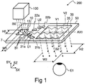
- a virtual display device 200 may comprise an optical engine 100 and a diffractive beam expander 50.
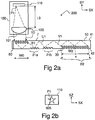
- the optical engine 100 may comprise a micro-display 110 and imaging optics 120 ( Fig. 2a ).
- the imaging optics 120 converts a real image 605 ( Fig. 2b ) formed by the micro-display 110 into a virtual image 710 ( Fig. 14 ) which is observable through a viewing aperture 35 of the diffractive beam expander 50.
- the diffractive beam expander 50 may comprise an input grating 10, two or more beam-deflecting grating portions 21a, 22a, two or more direction-restoring portions 21b, 22b, and an output grating 30.
- the gratings 10, 30 and the grating portions 21a, 22a, 21b, 22b may be implemented on a substantially planar transparent substrate 7.
- the substrate 7 has a first substantially planar surface and a second substantially planar surface which is substantially parallel to said first planar surface.
- the substrate 7 is waveguiding, which means that in-coupled light may propagate within said substrate 7 such that said propagating light may be confined to said substrate 7 by total internal reflections (TIR).
- TIR total internal reflections
- the optical engine 100 provides an input beam B0.
- the input beam B0 impinging on the input grating 10 may be coupled into the substrate 7 such that a corresponding in-coupled beam B1 propagates within said substrate towards the beam-deflecting portions 21a, 22a.
- the planar surfaces of the waveguiding substrate 7 are in planes defined by the orthogonal directions SX and SZ.
- the direction SY is perpendicular to the directions SX and SZ.
- the restored beam V1 has been shifted with respect to the original in-coupled beam B1 and it propagates substantially in the same direction as the original in-coupled beam B1.
- the restored beam V2 has been shifted with respect to the original in-coupled beam B1 it and propagates substantially in the same direction as the original in-coupled beam B1.
- a part of the in-coupled beam B1 may propagate within the substrate 7 without being diffracted by the portions 21a, 21b, 22a, 22b.
- the undiffracted part of the beam B1, the restored beam V1 and/or the restored beam V2 may together form an enlarged light beam which propagates in the same direction as the original in-coupled beam B1.
- the enlarged beam may be subsequently coupled out of the substrate 7 by the output grating 30 to provide an output beam B2 which is expanded in two directions SX and SZ when compared to the input beam B0.
- the output beam B2 may impinge on the eye E1 of an observer.
- the height H2 of the output beam B2 is greater than the height H0 of the input beam B0.
- the diffractive beam expander 50 provides beam expanding in the vertical direction SZ. (The direction SZ is vertical in the operating position shown in Fig. 14 ).
- the width W2 of the output beam B2 may be greater than the width W0 of the input beam B0.
- the maximum height H2 and the maximum width W2 of the output beam B2 are limited by the dimensions of the viewing aperture 35.
- the height and the width of the input grating 10 may be selected to be substantially equal to or grater than the dimensions of the input beam B0, in order to maximize the efficiency of coupling light into the substrate 7.
- the gratings 10, 30 and the grating portions 21a, 21b, 22a, 22b are diffractive elements.
- the gratings and the grating portions may be e.g. surface relief gratings implemented by molding or embossing on either of the planar surfaces 41, 42 ( Fig. 2a ).
- the profile of the gratings may be e.g. sinusoidal, binary rectangular, or blazed. Yet, the profile of the gratings may be binary slanted or sinusoidal slanted.
- One or more gratings 10, 30, and/or portions 21a, 21b, 22a, 22b may be embedded in the substrate 7.
- the diffractive beam expander 50 may further comprise auxiliary grating portions (see e.g. Fig. 9 ).
- the gratings 10, 30 and the grating portions 21 a, 21b, 22a, 22b may be in one or more planes defined by the directions SX and SZ.
- a midline AX1 may pass e.g. through the center of the aperture 15 of the input grating 10 and through the center of the aperture 35 of the output grating 30.
- the gratings 10, 30 and the portions 21a, 21b, 22a, 22b may be symmetrically positioned with respect said midline AX1.
- the midline AX1 may also be selected such that the gratings 10, 30 are not symmetrically positioned with respect to said midline AX1.
- the optical engine 100 may comprise a micro-display 110 and imaging optics 120.
- the imaging optics may comprise one or more optical elements such as lenses, mirrors, prisms or diffractive elements.
- Light rays transmitted from a point P1 of the micro-display are substantially collimated by the imaging optics 120 to form parallel rays of light which constitute the beam B0 provided by the optical engine 100.
- the distance L3 between the micro-display 110 and the imaging optics 120 is set such that the pixels of the micro-display 110 are substantially at the focal distance of the imaging optics 120.
- a plurality of beams B0 are provided in order to display a virtual image, which consists of a plurality of pixels.
- Light of the input beam B0 is coupled into the waveguiding substrate 7 by the input grating 10.
- the in-coupled light propagates within the substrate 7 as the in-coupled beam B1.
- a part of the in-coupled beam B1 interacts with the first deflecting grating portion 21a providing the deflected beam U1.
- a part of the deflected beam U1 interacts with the restoring grating portion 21b providing the first restored beam V1.
- a part of the in-coupled beam B1 remains undiffracted (not shown in Fig. 2a ).
- a part of the original in-coupled beam B1 may contribute to the second restored beam V2 (not shown in Fig. 2a ).
- the output grating 30 diffracts the expanded output beam B2 towards the eye E1 of the observer.
- the enlarged light beams B2 provided by the diffractive beam expander 50 provide for a viewer and impression of a virtual image 710 displayed at an infinite distance from the viewer.
- a virtual image 710 displayed at an infinite distance from the viewer.
- human viewers typically perceive that the displayed virtual image 710 is only a few meters away from them, despite the infinite distance.
- the virtual image 710 may be e.g. a star pattern, as shown in Fig. 14 .
- the diffractive beam expander 50 may be mono-ocular, i.e. it may have only one output grating 30.
- the input grating 10, the output grating 30 and or the grating portions 21a, 21b, 22a, 22b may be slanted or blazed surface relief gratings in order to maximize the efficiency of coupling light into the substrate 7 and out of the substrate 7.
- the diffractive beam expander 50 may comprise one or more optically absorbing structures 80 to eliminate stray light.
- the substrate 7 has a first substantially planar surface 41 and a second substantially planar surface 42 which is substantially parallel to said first planar surface 41.
- the gratings 10, 30 and the portions 21a, 21b, 22a, 22b may be on the same planar surface 41, 42, or on opposite surfaces 41, 42.
- the input grating 10 and the output grating 30 are on the first surface 41 and the portions 21a, 21b are on the second surface 42.
- the input beam B0 may also be transmitted through the substrate 7 before impinging on the input grating 10.
- the micro-display 110 may be e.g. a liquid crystal display, an array of micromechanically movable mirrors, an array of light emitting diodes, or a unit comprising at least one movable light-emitting point.
- the diagonal dimension of the micro-display may be e.g. smaller than or equal to 25 mm.
- Fig. 2b shows a real image 605 formed on the micro display 110.
- the real image 605 may be formed of light-emitting pixels or light-emitting points P1.
- the optical engine 100 may also comprise a light emitting point to provide a light beam and a beam-steering unit to rapidly vary the direction of said beam, wherein optical power provided by said light emitting point may be modulated based on the direction of said beam.
- the beam-steering unit may comprise e.g. one or more turning reflectors to change the direction of the beam.
- the optical engine 100 may also directly provide a virtual image by using a scanning method.
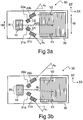
- a part of the in-coupled beam B1 may be diffracted by the first deflecting portion 21a to provide a first deflected beam U1.
- a part of the in-coupled beam B1 may be diffracted by the second deflecting portion 22a to provide a second deflected beam U2.
- the difference between the azimuth angle ⁇ 1 of said first deflected beam U1 and the azimuth angle ⁇ C (shown e.g. Fig. 3b ) of said in-coupled beam B1 is negative.
- the difference between the azimuth angle ⁇ 2 of said second deflected beam U2 and the azimuth angle ⁇ C of said in-coupled beam B1 is positive.
- the azimuth angle ⁇ 1 is the angle between the azimuthal direction of said first deflected beam U1 and the direction SX.
- the azimuth angle ⁇ 2 is the angle between the azimuthal direction of said second deflected beam U2 and the direction SX.
- the azimuth angle ⁇ C is the angle between the azimuthal direction of said in-coupled beam B1 and the direction SX.
- the azimuth angles ⁇ C , ⁇ 1 and ⁇ 2 are defined to be smaller than 180 degrees and greater than -180 degrees.
- a direction vector which has a positive azimuth angle has a component in the direction SZ, and a direction vector which has a negative azimuth angle has a component in a direction opposite the direction SZ.
- a part of the first deflected beam U1 is diffracted by the first restoring portion 21b to provide a first restored beam V1.
- the first restored beam V1 has the same azimuth angle ⁇ C as the original in-coupled beam B1.
- the difference between the negative azimuth angle ⁇ 1 and the azimuth angle ⁇ C is negative, and consequently the first restored beam V1 is shifted downwards with respect to the original in-coupled beam B1.
- a part of the second deflected beam U2 is diffracted by the second restoring portion 22b to provide a second restored beam V2 such that the second restored beam V2 the same azimuth angle ⁇ C as the original in-coupled beam B1.
- the difference between the positive azimuth angle ⁇ 2 and the azimuth angle ⁇ C is positive, and consequently the second restored beam V2 is shifted upwards, i.e. in the direction SZ with respect to the original in-coupled beam B1.
- the restored beams V1 and V2 form together an enlarged beam which has a greater height than the original in-coupled beam B1. Also that part of the in-coupled beam B1 which does not interact with the grating portions may contribute to the enlarged beam.
- a diffractive beam expander 50 may comprise a first intermediate grating 21, which in turn may comprise the first deflecting portion 21a and the first restoring portion 21b.
- the first intermediate grating 21 may be adapted to provide a first restored beam V1 which is shifted downwards with respect to the original in-coupled beam B1.
- the diffractive beam expander 50 may comprise a second intermediate grating 22 which in turn may comprise the second deflecting portion 22a and the second restoring portion 22b.
- the second intermediate grating 22 may be adapted to provide a second restored beam V2 which is shifted upwards with respect to the original in-coupled beam B1.
- Light may also be diffracted three or more times by the intermediate grating 21. If light is diffracted an even number of times so that each diffraction changes the azimuthal direction of light, then the final direction may still be substantially the same as the direction of the original in-coupled beam B1
- the intermediate gratings 21, 22 and the grating portions 21a, 21b, 22a, 22b are symmetrically positioned with respect to the midline AX1.
- the intermediate gratings 21, 22 and the grating portions 21a, 21b, 22a, 22b may also be asymmetrically positioned with respect to the midline AX1.
- the first intermediate grating 21 may comprise a first deflecting portion 21a and a first restoring portion 21b.
- the second intermediate grating 22 may comprise a second deflecting portion 22a and a second restoring portion 22b.
- the intermediate gratings 21, 22 may together form the shape of a chevron.
- the gratings 21, 22 may be substantially in contact with each other and with the midline AX1.
- the local width W(z) of the intermediate gratings may monotonically decrease with an increasing distance z from the midline AX1, when said distance z is greater than half of the height of the input grating 10.
- the local width W(z) of the intermediate gratings may monotonically increase with an increasing distance z from the midline AX1.
- the first deflecting portion 21a and the corresponding first restoring portion 21b may be on opposite sides of the midline AX1, when viewed from a direction perpendicular to the planes of the waveguiding substrate 7. Consequently, the first deflected beam U1 diffracted by the first deflecting portion 21a crosses the midline AX1 before impinging on the first restoring portion 21b.
- the second deflecting portion 22a and the corresponding second restoring portion 22b may be on opposite sides of the midline AX1. Consequently, the second deflected beam U2 diffracted by the second deflecting portion 22a crosses the midline AX1 before impinging on the second restoring portion 22b.
- the arrangement shown in Fig. 8a guides the light more to the direction where the gaze is. This improves the observed brightness of the image especially at the extreme angles of the field of view than the arrangements in Fig. 7 , for example when the zenith angle ⁇ IN of the input beam B0 is greater than or equal to 5 degrees ( Fig. 12c ).
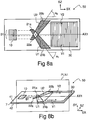
- Fig. 8b shows a three-dimensional view of the situation of Fig. 8a .
- a reference plane PLN1 is perpendicular to the plane of the input grating 10 and the planes 41, 42 of the waveguiding substrate 7 of the beam expanding device 50.
- the mid-line AX1 represents an intersection of the plane PLN1 with the plane 41 or 42 of the substrate 7.
- the reference plane PLN1 may be e.g. a plane defined by the directions SX and SY.
- the portions 21a, 21b, 22a, 22b may be positioned symmetrically or asymmetrically with respect to said plane PLN1.
- the first deflection portion 21a and the second restoring portion 22b may be on a first side of the reference plane PLN1.
- the second deflecting portion 22b and the first restoring portion 21b may be on a second side of said reference plane PLN1.
- the first deflecting portion 21a is adapted to provide the first deflected beam U1 by diffracting light of the in-coupled beam B1 such that the first deflected beam U1 passes from the first side of the plane PLN1 to the second side of the plane PLN before impinging on the first restoring portion 21b.
- the second deflecting portion 22a is adapted to provide the second deflected beam U2 by diffracting light of the in-coupled beam B1 such that the second deflected beam U2 passes from the second side of said plane PLN1 to the first side of the plane PLN1 before impinging on the second restoring portion 22b.
- the reference plane PLN1 may intersect the input grating 10 and the output grating 30.
- the reference plane PLN1 may substantially intersect the centers of the apertures 15, 35 of the gratings 10, 30 ( Fig. 1 ).
- Fig. 8c shows paths of light rays propagating in the diffractive beam expander of Fig. 8a .
- a first in-coupled light ray B1 a corresponds to light emitted from a first pixel which is on a first edge or corner of the micro-display 110 ( Figs. 2a and 2b ).
- a second in-coupled light ray B1 b corresponds to light emitted from a second pixel which is on a second edge or corner of said micro-display 110.
- the first in-coupled ray B1 a has an azimuth angle ⁇ a and the second in-coupled ray B1 b has an azimuth angle ⁇ b .
- Said first and second pixels are selected such that the azimuth angles of substantially all in-coupled rays corresponding to the displayed image are smaller than or equal to ⁇ a and greater than or equal to ⁇ b .
- Diffraction of the first in-coupled ray B1 a on the first deflecting portion 21a may provide a first deflected ray U1 a
- diffraction of the second in-coupled ray B1 b on said first deflecting portion 21a may provide a second deflected ray U1 b
- ⁇ denotes an angle between the first and the second deflected rays U1 a , U1 b .
- Diffraction of the first deflected ray U1 a on the first restoring portion 21b may provide a first restored ray V1 a
- diffraction of the second deflected ray U1 b on said first restoring portion 21b may provide a second restored ray V1 b
- the first restored ray V1 a has the azimuth angle ⁇ a
- the second restored ray V1 b has the azimuth angle ⁇ b .
- the first restored ray V1 a propagates in the same direction as the first in-coupled ray B1 a
- the second restored ray V1 b propagates in the same direction as the second in-coupled ray B1 b .
- the forms and the positions of the first deflecting portion 21a, of the second deflecting portion 22a, of the first restoring portion 21b and of the second deflecting portion 22b may be selected such that light rays deflected from the first deflecting portion 21a do not impinge on the second deflecting portion 22a, and such that light rays deflected from the first deflecting portion 21a do not impinge on the second restoring portion 22b, and such that that light rays deflected from the second deflecting portion 22a do not impinge on the first deflecting portion 21a, and such that light rays deflected from the second deflecting portion 22a do not impinge on the first restoring portion 21b, wherein said light rays correspond to extreme points on the image area of said micro-display 110.
- diffractive beam expanders 50 shown in Figs 3a to 10c may fulfil the above-mentioned condition.
- the extreme azimuth angles ⁇ a and ⁇ b may be selected by choosing the dimensions of the micro-display 110 and the focal length of the imaging optics 120.
- the diffractive beam expander 50 may comprise substantially non-diffracting portions 26, 27 and/or a substantially non-diffraction portion 25 in order to fulfil the above-mentioned condition.
- the portions 21a, 21b, 22a, 22b may be arranged e.g. in a crossed wedge formation shown e.g. in Figs 8a and 8c in order to fulfil the above-mentioned condition.
- the sides of the wedges may be substantially aligned with the directions of the deflected light rays.
- a first side of the portion 21a and a first side of the portion 21b may be aligned with the first deflected ray U1 a
- a second side of the portion 21a and a second side of the portion 21b may be aligned with the second deflected ray U1 b .
- a side of the portion 22a may be substantially aligned with the deflected light ray U1 a
- a side of the portion 22b may be substantially parallel to the deflected light ray U1 b .
- a single pixel P1 of the micro-display 110 provides a plurality of in-coupled rays which propagate in the same direction defined by a single azimuth angle, said rays constituting an in-coupled beam B1.
- the beam expanding device 50 provides an output beam B2 for each pixel of the micro-display 110.
- the plurality of the output beams B2 provide for the viewer E1 an impression of a virtual image.
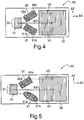
- the diffractive beam expander 50 may comprise auxiliary deflecting portions 21c, 22c to provide further deflected beams U1c, U2c.
- the further deflected beams U1c, U2c may impinge on the restoring portions 21b, 22b to provide further restored beams V1c, V2c such that the further restored beams V1c, V2c together with the beams V1, V2 propagate in the same direction as the original in-coupled beam B1.
- the further deflected beams U1c, U2c may impinge on the restoring portions 21b, 22b without crossing the midline AX1, i.e. without passing through the plane PLN1.
- the arrangement of Fig. 9 provides better uniformity of the observed brightness and a higher throughput efficiency at extreme angles of the field of view than the arrangement of Fig. 8 , i.e. when the observer is gazing upper or lower edges of the field of view.
- a first auxiliary deflecting portion 21c and the first restoring portion 21b may be portions of a first intermediate grating 21, which is located on the lower side of the midline AX1, i.e. on the second side of the reference plane PLN1).
- a second auxiliary deflecting portion 22c and the second restoring portion 22b may be portions of a second intermediate grating 22, which is located on the upper side of the midline AX1, i.e. on the first side of the reference plane PLN1.
- the first deflecting portion 21a may be located on the upper side of the midline AX1 and on the first side of the reference plane PLN1.
- the deflecting portions 21a, 21c may provide deflected beams which impinge on the first restoring portion 21b.
- the form of the first deflecting portion 21a may be substantially a polygon defined by the height of the in-coupling grating 10 and the directions of light propagating inside the substrate so that none of the light rays deflected from the deflecting portion 21a impinge on the second intermediate grating 22 and so that none of the light rays deflected from the deflecting portion 22a impinge on the first intermediate grating 21.
- the form of the first intermediate grating 21 may be substantially a polygon fulfilling a condition that none of the light rays deflected from the deflecting portion 22a impinge on said intermediate grating 21.
- the second deflecting portion 22a may be substantially a mirror image of the first deflecting portion 21a with respect to the midline AX1.
- the second intermediate grating 22 may be substantially a mirror image of the first intermediate grating 21 with respect to the midline AX1.
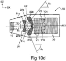
- Fig. 10a provides a high throughput efficiency and a quite uniform intensity distribution over the field of view.
- the form and the position of the deflecting portions 21a, 22a, 21c, 22c and the restoring portions 21b, 22b may be further selected to reduce beam divergence caused by aperture-related diffraction, when compared with the device of Fig. 10a .
- Larger dimensions of the auxiliary deflecting portions 21c, 22c provide less diverging beams than in case of Fig. 10a .
- the coordinates of the corner points of the in-coupling grating 10 may be (0.00, 3,50), (3.50, 3.50), (3.50, -3.50), and (0.00, - 3.50).
- the first coordinate represents a position in the direction SX and the second coordinate represents a position in the direction SZ.
- the corner points of the first deflecting portion 21a may be (13.40, 0.00), (11.61, 5.08), (13.72, 5.37), and (14.84, 4.09).
- the corner points of the first intermediate grating 21, may be (15.79, -6.80), (16.22, -8.00), (18.86, -8.00), (21.22, -1.40), (20.22, 0.00), (18.62, 0.00), (20.13, - 1.30), and (17.00, -4.00).
- the corner points of the output grating 30 may be (22.00, 7.00), (43.00, 7.00), (43.00, -7.00), and (22.00, -7.00).
- the in-coupled beam B1 may be adapted to shift in the direction SZ with respect to the deflecting portions 21a, 21b according to the azimuth angle ⁇ C of said in-coupled beam B1.
- the height of a first part of the in-coupled beam B1 impinging on the first deflecting portion 21a may be greater than the height of a second part of said in-coupled beam B1 impinging on the second deflecting portion 22a when the azimuth angle ⁇ C is greater than zero, and the height of said first part of the in-coupled beam B1 impinging on the first deflecting portion 21a may be smaller than the height of the second part of said in-coupled beam B1 impinging on the second deflecting portion 22a when the azimuth angle ⁇ C is smaller than zero.
- Said heights are defined in the direction SZ.
- the relationship between said shifting and the azimuth angle ⁇ C depends on the distance L12 between the input grating 10 and the deflecting portions 21a, 22a.
- the distance L12 may be e.g. greater than 0.3 times a distance L13 between the input grating 10 and the output grating 30.
- the distance L12 may be even greater than or equal to 0.5 times the distance L13.
- the distance L12 may be e.g. greater than or equal to the height H0 ( Fig. 1 ) of the input beam B0.
- the area between the input grating 10 and the deflecting portions 21a, 22a may be substantially non-diffracting.
- the deflecting portions 21a, 21c, 22a, and 22c provide deflected beams U1, U2, and the restoring portions 21b, 22b provide restored beams V1, V1c, V2, V2c having the same azimuth angle ⁇ C as the in-coupled beam B1.
- the difference between the azimuth angle ⁇ 1 of the first deflected beam U1 and the azimuth angle ⁇ C of the in-coupled beam B1 is negative.
- the difference between the azimuth angle ⁇ 2 of the second deflected beam U1 and the azimuth angle ⁇ C of the in-coupled beam B1 is positive.
- the portions 21a, 22b, 22c are on a first side of the mid-line AX1 and on the first side of the reference plane PLN1.
- the portions 22a, 21b, 21c are on a second side of the mid-line AX1 and on the second side of the reference plane PLN1.
- the input grating 10 comprises a plurality of substantially linear diffractive features DF 10 , which have a grating period d 0 .
- the output grating 30 comprises a plurality of substantially linear diffractive features DF 30 .
- the grating period of the output grating 30 may also be substantially equal to d 0 .
- the diffractive features DF 10 and DF 30 may be e.g. adjacent grooves or ridges.
- the grating period d 0 of the input grating 10 may be selected to provide only four diffraction orders, namely the reflective diffraction orders 1 and -1 and the transmissive diffraction orders 1 and -1, which may reflectively and/or transmissively couple light into the substrate 7.
- the input grating 10 may also diffract light in the transmissive diffraction order 0 which corresponds to direct transmission through the grating and/or in the reflective diffraction order 0 which corresponds to direct reflection from the grating. If the input grating 10 has a slanted profile, then it may be adapted to provide substantially one first order diffraction, namely 1 or -1.
- the diffractive features DF 10 may be substantially parallel to the diffractive features DF 30 .
- the diffractive features DF 10 and DF 30 may be substantially parallel to the direction SZ and perpendicular to the midline AX1.
- the first deflecting grating portion 21a has a plurality of diffractive features F 21a , which have an angle ⁇ 21a with respect to the direction SZ.
- the first deflecting grating portion 21a has a grating period d 21a .
- the second deflecting grating portion 22a has a plurality of diffractive features F 22a , which have an angle ⁇ 22a with respect to the direction SZ.
- the second deflecting grating portion 22a has a grating period d 22a .
- the first restoring grating portion 21b has a plurality of diffractive features F 21b , which have an angle ⁇ 21b with respect to the direction SZ.
- the first restoring grating portion 21b has a grating period d 21b .
- the second restoring grating portion 22b has a plurality of diffractive features F 22b , which have an angle ⁇ 22b with respect to the direction SZ.
- the second restoring grating portion 22b has a grating period d 22b .
- d 0 is the grating period of the input grating 10
- a 0 is a constant having a value in the range of 1.8 to 2.2.
- the constant A 0 may be substantially equal to two.
- the grating periods of the grating portions 21a, 21b, 22a, 22b, 21c, 22c may now be solved using eq. (1).
- the grating periods of the grating portions 21a, 21b, 22a, 22b, 21c, 22c may be selected using eq. (1) such that diffraction is allowed only in the zeroth and in the first diffraction modes.
- the sign of the first order diffraction depends on the chosen coordinates.
- the angle ⁇ 21a between the direction of the diffractive features F 21a of said first deflecting grating portion 21a and the direction SZ of the diffractive features DF 11 of said input grating 10 may be in the range of 55 to 65 degrees.
- the orientation angle ⁇ 21a may be substantially equal to 60 degrees.
- the orientation angle ⁇ 22a may be substantially equal to 120 degrees, respectively.
- the first deflecting portion 21a and the first restoring portion 21b may have the same orientation of diffractive features and the same grating period.
- the second deflecting portion 22a and the second restoring portion 22b may have the same orientation of diffractive features and the same grating period.
- the first auxiliary reflecting portion 21c (not shown in Figs. 11a and 11b ) and the first restoring portion 21b may have the same orientation of diffractive features and the same grating period.
- the second auxiliary reflecting portion 22c (not shown in Figs. 11a and 11b ) and the second restoring portion 22b may have the same orientation of diffractive features and the same grating period.
- Fig. 12a shows the azimuth angle ⁇ IN of the input beam B0 and the zenith angle ⁇ IN of the input beam B0.
- the zenith angle ⁇ IN is an angle between the direction of the beam B0 and the direction -SY.
- the direction -SY is opposite the direction SY.
- the surface normal of the input grating 10 is parallel to the direction SY.
- the azimuth angle ⁇ IN is an angle between the projection PR0 and the direction SX, wherein said projection PR0 is the projection of the direction of the input beam B0 in a plane defined by the directions SX and SZ.
- the projection PR0 is the left side of the azimuth angle.
- the projection of the input beam B0 on the SX-SZ-plane has the azimuth angle ⁇ IN with respect to the direction SX.
- the projections of the in-coupled beam B1 and the restored beams V1, V2 have an azimuth angle ⁇ C with respect to the direction SX.
- the projection of the output beam B2 has an azimuth angle ⁇ OUT with respect to the direction SX.
- the direction of the input beam B0 has a zenith angle ⁇ IN with respect to the direction -SY.
- the direction of the in-coupled beam B1 has a zenith angle ⁇ C with respect to the direction - SY.
- the direction of the output beam B2 has a zenith angle ⁇ OUT with respect to the direction -SY.
- the diffractive beam expander 50 may also be bi-ocular.
- the input grating 10 may be adapted to diffract light towards a first set of intermediate gratings 21, 22 and also towards a second set of intermediate gratings 21', 22'.
- the expander 50 may have a first output grating 30 to provide a beam B2 for a right eye of an observer, and a second output grating 30' to provide a second beam B2 for a left eye of an observer.
- the diffractive beam expander 50 may be used to implement a virtual display device 200 shown in Fig. 14 .
- the output beams B2 provided by the output gratings 30, 30' to the eyes E1, E2 of a viewer provide for the viewer an impression of a virtual image 710 displayed at an infinite distance from the viewer.
- the virtual image 710 may be e.g. a star pattern as shown in Fig. 14 , corresponding to a real image 605 generated by the micro-display 110 ( Fig. 2b ).
- the virtual image 710 may be e.g. graphics and/or text.
- the display device of Fig. 14 may further comprise earpieces 260 which may be positioned on the ears of the viewer in order to facilitate positioning of the diffractive beam expander 50 in front of the viewer.
- the display device 200 may also be attached to a headgear, e.g. to a helmet.
- a bi-ocular display device 200 may comprise two separate optical engines 100 and two separate mono-ocular beam expanders 50 in order to show stereoscopic virtual images.
- the diffractive beam expander 50 may be partially transparent, allowing the user to see his environment through the viewing aperture 35 of the expander 50 while also viewing a displayed virtual image 710. This transparent arrangement may be applied e.g. in augmented reality systems.
- Fig. 15 shows a device 200 comprising a mono-ocular virtual display implemented by using the diffractive beam expander 50.
- the device 200 may further comprise e.g. a key set 230 for controlling said device.
- the device 200 of Fig. 14 or 15 may further comprise e.g. a data processing unit, memory and communications unit to provide access to a mobile telephone network, internet or local area network.
- the device 200 may be, for example, selected from the following list: a display module connectable to a further device, portable device, device with wireless telecommunicating capabilities, imaging device, mobile phone, gaming device, music recording/playing device (based on e.g. MP3-format), remote control transmitter or receiver, navigation instrument, measuring instrument, target finding device, aiming device, navigation device, personal digital assistant (PDA), communicator, portable internet appliance, hand-held computer, accessory to a mobile phone.
- PDA personal digital assistant
- Showing of virtual images at distances shorter than infinity may be implemented using a diffractive beam expander 50 comprising nonplanar output grating having a finite curvature radius, as disclosed e.g. in a patent application PCT/IB2004/004094 .
- a device 50 comprising: a substantially planar waveguiding substrate 7; an input grating 10 to provide an in-coupled beam B1 propagating within said substrate 7 by diffracting light of an input beam B0 into said substrate 7; a first deflecting grating portion 21a to provide a first deflected beam U1 by diffracting a part of said in-coupled beam B1 such that the difference between the azimuth angle ⁇ 1 of said first deflected beam U1 and the azimuth angle ⁇ C of said in-coupled beam B1 is negative, said first deflecting grating portion 21a comprising substantially linear diffractive features F 21a ; a second deflecting grating portion 22a to provide a second deflected beam U2 by diffracting a part of said in-coupled beam B1 such that the difference between the azimuth angle ⁇ 2 of said second deflected beam U2 and the azimuth angle ⁇ C of said in
- Said first deflecting grating portion 21a and said second restoring grating portion 22b may be on a first side of a reference plane PLN1, and said second deflecting grating portion 22a and said first restoring grating portion 21b may be on a second side of said reference plane PLN1, said reference plane PLN1 being substantially perpendicular to the plane of said input grating 10.
- the device 50 may comprise a third deflecting grating portion 21c to provide a third deflected beam U1c by diffracting a part of said in-coupled beam B0 such that the azimuth angle of said third deflected beam U1c is smaller than the azimuth angle ⁇ C of said in-coupled beam B1, said third deflected beam U1c being adapted to impinge on a restoring grating portion 21c to provide a third restored beam V1c having the same direction as said first restored beam V1, said third deflecting grating portion 21c being on the second side of said reference plane PLN1.
- Said first restoring portion 21b and said third deflecting grating portion 21c may form together a first intermediate grating 21 having a substantially continuous grating structure.
- Said in-coupled beam B1 may be adapted to shift with respect to said deflecting portions 21a, 22a according to the direction ⁇ C of said in-coupled beam B1.
- Said first restored beam V1 and said second restored beam V2 may be substantially parallel to the direction of said in-coupled beam B1, and the output grating 30 may be further adapted to diffract a part of said in-coupled beam B1 out of said substrate 7.
- An angle ⁇ 21a between the direction of the diffractive features F 21a of said first deflecting grating portion 21a and the direction SZ of the diffractive features DF 11 of said input grating 10 may be in the range of 55 to 65 degrees.
- a method for expanding a light beam comprising: diffracting light of an input beam B0 into a substantially planar waveguiding substrate 7 in order to provide an in-coupled beam B1 propagating within said substrate 7; providing a first deflected beam U1 by diffracting a part of said in-coupled beam B1 by using a first deflecting grating portion 21a such that the difference between the azimuth angle ⁇ 1 of said first deflected beam U1 and the azimuth angle ⁇ C of said in-coupled beam B1 is negative; providing a second deflected beam U2 by diffracting a part of said in-coupled beam B1 by using a second deflecting grating portion 22a such that the difference between the azimuth angle ⁇ 2 of said second deflected beam U2 and the azimuth angle ⁇ C of said in- coupled beam B1 is positive; providing a first restored beam V1 by diffracting a part of said first
- Said first deflecting grating portion 21a and said second restoring grating portion 22b may be on a first side of a reference plane PLN1, and said second deflecting grating portion 22a and said first restoring grating portion 21 b may be on a second side of reference plane PLN1, said reference plane PLN1 being substantially perpendicular to the plane of said input grating 10.
- a device 200 comprising an optical engine 100 to provide at least one light beam B0, and a diffractive beam expander 50 to expand said at least one light beam B0 such that a virtual image 710 is observable through a viewing aperture 35 of said diffractive beam expander 50, said diffractive beam expander 50 in turn comprising: a substantially planar waveguiding substrate 7; an input grating 10 to provide an in-coupled beam B1 propagating within said substrate 7 by diffracting light of an input beam B0 into said substrate 7; a first deflecting grating portion 21a to provide a first deflected beam U1 by diffracting a part of said in-coupled beam B1 such that the difference between the azimuth angle ⁇ 1 of said first deflected beam U1 and the azimuth angle ⁇ C of said in-coupled beam B1 is negative, said first deflecting grating portion 21a comprising substantially linear diffractive features F 21a ;
- Said optical engine 100 comprises a micro-display 110 to display a real image 605.
- a method comprising providing at least one input beam B0 and expanding said at least one input beam B0 such that a virtual image is observable through a viewing aperture 35, said expanding comprising: diffracting light of said input beam B0 into a substantially planar waveguiding substrate 7 in order to provide an in-coupled beam B1 propagating within said substrate 7; providing a first deflected beam U1 by diffracting a part of said in-coupled beam B1 by using a first deflecting grating portion 21a such that the difference between the azimuth angle ⁇ 1 of said first deflected beam U1 and the azimuth angle ⁇ C of said in-coupled beam B1 is negative; providing a second deflected beam U2 by diffracting a part of said in-coupled beam B1 by using a second deflecting grating portion 22a such that the difference between the azimuth angle ⁇ 2 of said second deflected beam U2 and the azimuth
- Said first deflecting grating portion 21a and said second restoring grating portion 22b may be on a first side of a reference plane PLN1, and said second deflecting grating portion 22a and said first restoring grating portion 21b may be on a second side of said reference plane PLN1 said reference plane PLN1 being substantially perpendicular to the plane of said input grating 10.
- a device 50 comprising: a waveguiding means 7; a diffractive input means 10 to provide an in-coupled beam B1 propagating within said substrate 7 by diffracting light of an input beam B0 into said waveguiding means 7; a first deflecting means 21a to provide a first deflected beam U1 by diffracting a part of said in-coupled beam B1 such that the difference between the azimuth angle ⁇ 1 of said first deflected beam U1 and the azimuth angle ⁇ C of said in-coupled beam B1 is negative, said first deflecting means 21a comprising substantially linear diffractive features F 21a ; a second deflecting means 22a to provide a second deflected beam U2 by diffracting a part of said in-coupled beam B0 such that the difference between the azimuth angle ⁇ 2 of said second deflected beam U2 and the azimuth angle ⁇ C of said in-coupled beam B1 is positive
- Said first deflecting means 21a and said second restoring means 22b may be on a first side of a plane PLN1, and said second deflecting means 22a and said first restoring means 21b may be on a second side of said plane PLN1, said reference plane PLN1 being substantially perpendicular to the plane of said diffractive input means 10.
Priority Applications (1)
| Application Number | Priority Date | Filing Date | Title |
|---|---|---|---|
| EP20154070.5A EP3667399A1 (de) | 2007-06-04 | 2007-06-04 | Diffraktiver strahlaufweiter |
Applications Claiming Priority (3)
| Application Number | Priority Date | Filing Date | Title |
|---|---|---|---|
| EP20154070.5A EP3667399A1 (de) | 2007-06-04 | 2007-06-04 | Diffraktiver strahlaufweiter |
| PCT/FI2007/050322 WO2008148927A1 (en) | 2007-06-04 | 2007-06-04 | A diffractive beam expander and a virtual display based on a diffractive beam expander |
| EP07730809.6A EP2153266B1 (de) | 2007-06-04 | 2007-06-04 | Beugende strahlaufweitungsvorrichtung und virtuelles display auf der basis einer beugenden strahlaufweitungsvorrichtung |
Related Parent Applications (2)
| Application Number | Title | Priority Date | Filing Date |
|---|---|---|---|
| EP07730809.6A Division EP2153266B1 (de) | 2007-06-04 | 2007-06-04 | Beugende strahlaufweitungsvorrichtung und virtuelles display auf der basis einer beugenden strahlaufweitungsvorrichtung |
| EP07730809.6A Division-Into EP2153266B1 (de) | 2007-06-04 | 2007-06-04 | Beugende strahlaufweitungsvorrichtung und virtuelles display auf der basis einer beugenden strahlaufweitungsvorrichtung |
Publications (1)
| Publication Number | Publication Date |
|---|---|
| EP3667399A1 true EP3667399A1 (de) | 2020-06-17 |
Family
ID=40093228
Family Applications (2)
| Application Number | Title | Priority Date | Filing Date |
|---|---|---|---|
| EP07730809.6A Active EP2153266B1 (de) | 2007-06-04 | 2007-06-04 | Beugende strahlaufweitungsvorrichtung und virtuelles display auf der basis einer beugenden strahlaufweitungsvorrichtung |
| EP20154070.5A Pending EP3667399A1 (de) | 2007-06-04 | 2007-06-04 | Diffraktiver strahlaufweiter |
Family Applications Before (1)
| Application Number | Title | Priority Date | Filing Date |
|---|---|---|---|
| EP07730809.6A Active EP2153266B1 (de) | 2007-06-04 | 2007-06-04 | Beugende strahlaufweitungsvorrichtung und virtuelles display auf der basis einer beugenden strahlaufweitungsvorrichtung |
Country Status (4)
| Country | Link |
|---|---|
| US (1) | US8320032B2 (de) |
| EP (2) | EP2153266B1 (de) |
| CN (1) | CN101688977B (de) |
| WO (1) | WO2008148927A1 (de) |
Families Citing this family (248)
| Publication number | Priority date | Publication date | Assignee | Title |
|---|---|---|---|---|
| US8272758B2 (en) | 2005-06-07 | 2012-09-25 | Oree, Inc. | Illumination apparatus and methods of forming the same |
| WO2006131924A2 (en) | 2005-06-07 | 2006-12-14 | Oree, Advanced Illumination Solutions Inc. | Illumination apparatus |
| US8215815B2 (en) | 2005-06-07 | 2012-07-10 | Oree, Inc. | Illumination apparatus and methods of forming the same |
| GB0522968D0 (en) | 2005-11-11 | 2005-12-21 | Popovich Milan M | Holographic illumination device |
| GB0718706D0 (en) | 2007-09-25 | 2007-11-07 | Creative Physics Ltd | Method and apparatus for reducing laser speckle |
| US20100302644A1 (en) * | 2007-09-18 | 2010-12-02 | Mirage Innovations Ltd | Slanted optical device |
| US7907804B2 (en) | 2007-12-19 | 2011-03-15 | Oree, Inc. | Elimination of stitch artifacts in a planar illumination area |
| US8182128B2 (en) | 2007-12-19 | 2012-05-22 | Oree, Inc. | Planar white illumination apparatus |
| CN101978297A (zh) | 2008-03-05 | 2011-02-16 | 奥利高级照明解决公司 | 照明装置及其形成方法 |
| US8297786B2 (en) | 2008-07-10 | 2012-10-30 | Oree, Inc. | Slim waveguide coupling apparatus and method |
| US8301002B2 (en) | 2008-07-10 | 2012-10-30 | Oree, Inc. | Slim waveguide coupling apparatus and method |
| EP2196843A1 (de) * | 2008-12-12 | 2010-06-16 | BAE Systems PLC | Verbesserungen an oder im Zusammenhang mit Wellenleitern |
| WO2010067116A1 (en) * | 2008-12-12 | 2010-06-17 | Bae Systems Plc | Improvements in or relating to waveguides |
| US8624527B1 (en) | 2009-03-27 | 2014-01-07 | Oree, Inc. | Independently controllable illumination device |
| EP2241926A1 (de) * | 2009-04-14 | 2010-10-20 | BAE Systems PLC | Optischer Wellenleiter und Anzeigevorrichtung |
| ES2644595T3 (es) | 2009-04-14 | 2017-11-29 | Bae Systems Plc | Guía de ondas óptica y dispositivo de visualización |
| US11726332B2 (en) | 2009-04-27 | 2023-08-15 | Digilens Inc. | Diffractive projection apparatus |
| US9335604B2 (en) | 2013-12-11 | 2016-05-10 | Milan Momcilo Popovich | Holographic waveguide display |
| US8328406B2 (en) | 2009-05-13 | 2012-12-11 | Oree, Inc. | Low-profile illumination device |
| WO2010150202A2 (en) | 2009-06-24 | 2010-12-29 | Oree, Advanced Illumination Solutions Inc. | Illumination apparatus with high conversion efficiency and methods of forming the same |
| US8194325B2 (en) * | 2009-06-30 | 2012-06-05 | Nokia Corporation | Optical apparatus and method |
| US10795160B1 (en) | 2014-09-25 | 2020-10-06 | Rockwell Collins, Inc. | Systems for and methods of using fold gratings for dual axis expansion |
| US11300795B1 (en) | 2009-09-30 | 2022-04-12 | Digilens Inc. | Systems for and methods of using fold gratings coordinated with output couplers for dual axis expansion |
| US11320571B2 (en) | 2012-11-16 | 2022-05-03 | Rockwell Collins, Inc. | Transparent waveguide display providing upper and lower fields of view with uniform light extraction |
| US8233204B1 (en) | 2009-09-30 | 2012-07-31 | Rockwell Collins, Inc. | Optical displays |
| US20200057353A1 (en) | 2009-10-09 | 2020-02-20 | Digilens Inc. | Compact Edge Illuminated Diffractive Display |
| US11204540B2 (en) | 2009-10-09 | 2021-12-21 | Digilens Inc. | Diffractive waveguide providing a retinal image |
| US8659826B1 (en) | 2010-02-04 | 2014-02-25 | Rockwell Collins, Inc. | Worn display system and method without requiring real time tracking for boresight precision |
| US9753297B2 (en) * | 2010-03-04 | 2017-09-05 | Nokia Corporation | Optical apparatus and method for expanding an exit pupil |
| US8467643B2 (en) * | 2010-08-13 | 2013-06-18 | Toyota Motor Engineering & Mfg. North America, Inc. | Optical device using double-groove grating |
| US9507149B2 (en) | 2010-10-19 | 2016-11-29 | Bae Systems Plc | Image combiner |
| US20120108298A1 (en) * | 2010-10-29 | 2012-05-03 | Symbol Technologies, Inc. | Portable device having a virtual display |
| US9274349B2 (en) | 2011-04-07 | 2016-03-01 | Digilens Inc. | Laser despeckler based on angular diversity |
| US8548290B2 (en) * | 2011-08-23 | 2013-10-01 | Vuzix Corporation | Dynamic apertured waveguide for near-eye display |
| WO2016020630A2 (en) | 2014-08-08 | 2016-02-11 | Milan Momcilo Popovich | Waveguide laser illuminator incorporating a despeckler |
| US10670876B2 (en) | 2011-08-24 | 2020-06-02 | Digilens Inc. | Waveguide laser illuminator incorporating a despeckler |
| EP2748670B1 (de) | 2011-08-24 | 2015-11-18 | Rockwell Collins, Inc. | Tragbare datenanzeige |
| CN104040410B (zh) * | 2011-08-29 | 2017-06-09 | 伊奎蒂公司 | 用于近眼显示器应用的可控波导 |
| US8957397B2 (en) | 2011-09-26 | 2015-02-17 | Siemens Medical Solutions Usa, Inc. | Multilayer, multiaperture collimator for medical imaging and fabrication method |
| US9715067B1 (en) | 2011-09-30 | 2017-07-25 | Rockwell Collins, Inc. | Ultra-compact HUD utilizing waveguide pupil expander with surface relief gratings in high refractive index materials |
| US9366864B1 (en) | 2011-09-30 | 2016-06-14 | Rockwell Collins, Inc. | System for and method of displaying information without need for a combiner alignment detector |
| US9599813B1 (en) | 2011-09-30 | 2017-03-21 | Rockwell Collins, Inc. | Waveguide combiner system and method with less susceptibility to glare |
| US8634139B1 (en) | 2011-09-30 | 2014-01-21 | Rockwell Collins, Inc. | System for and method of catadioptric collimation in a compact head up display (HUD) |
| GB201117029D0 (en) * | 2011-10-04 | 2011-11-16 | Bae Systems Plc | Optical waveguide and display device |
| US8591072B2 (en) | 2011-11-16 | 2013-11-26 | Oree, Inc. | Illumination apparatus confining light by total internal reflection and methods of forming the same |
| KR102513896B1 (ko) | 2011-11-23 | 2023-03-23 | 매직 립, 인코포레이티드 | 3차원 가상 및 증강 현실 디스플레이 시스템 |
| US20150010265A1 (en) | 2012-01-06 | 2015-01-08 | Milan, Momcilo POPOVICH | Contact image sensor using switchable bragg gratings |
| US9052414B2 (en) * | 2012-02-07 | 2015-06-09 | Microsoft Technology Licensing, Llc | Virtual image device |
| US9075566B2 (en) | 2012-03-02 | 2015-07-07 | Microsoft Technoogy Licensing, LLC | Flexible hinge spine |
| US9460029B2 (en) | 2012-03-02 | 2016-10-04 | Microsoft Technology Licensing, Llc | Pressure sensitive keys |
| US9870066B2 (en) | 2012-03-02 | 2018-01-16 | Microsoft Technology Licensing, Llc | Method of manufacturing an input device |
| US11068049B2 (en) * | 2012-03-23 | 2021-07-20 | Microsoft Technology Licensing, Llc | Light guide display and field of view |
| US9523852B1 (en) | 2012-03-28 | 2016-12-20 | Rockwell Collins, Inc. | Micro collimator system and method for a head up display (HUD) |
| CN106125308B (zh) | 2012-04-25 | 2019-10-25 | 罗克韦尔柯林斯公司 | 用于显示图像的装置和方法 |
| WO2013167864A1 (en) | 2012-05-11 | 2013-11-14 | Milan Momcilo Popovich | Apparatus for eye tracking |
| US20130300590A1 (en) | 2012-05-14 | 2013-11-14 | Paul Henry Dietz | Audio Feedback |
| US10031556B2 (en) | 2012-06-08 | 2018-07-24 | Microsoft Technology Licensing, Llc | User experience adaptation |
| US9019615B2 (en) | 2012-06-12 | 2015-04-28 | Microsoft Technology Licensing, Llc | Wide field-of-view virtual image projector |
| WO2014006501A1 (en) | 2012-07-03 | 2014-01-09 | Yosi Shani | Planar remote phosphor illumination apparatus |
| US9355345B2 (en) | 2012-07-23 | 2016-05-31 | Microsoft Technology Licensing, Llc | Transparent tags with encoded data |
| US8885997B2 (en) * | 2012-08-31 | 2014-11-11 | Microsoft Corporation | NED polarization system for wavelength pass-through |
| US9152173B2 (en) | 2012-10-09 | 2015-10-06 | Microsoft Technology Licensing, Llc | Transparent display device |
| US9933684B2 (en) * | 2012-11-16 | 2018-04-03 | Rockwell Collins, Inc. | Transparent waveguide display providing upper and lower fields of view having a specific light output aperture configuration |
| US9513748B2 (en) | 2012-12-13 | 2016-12-06 | Microsoft Technology Licensing, Llc | Combined display panel circuit |
| US9638835B2 (en) | 2013-03-05 | 2017-05-02 | Microsoft Technology Licensing, Llc | Asymmetric aberration correcting lens |
| WO2014155096A1 (en) * | 2013-03-28 | 2014-10-02 | Bae Systems Plc | Improvements in and relating to displays |
| US9674413B1 (en) | 2013-04-17 | 2017-06-06 | Rockwell Collins, Inc. | Vision system and method having improved performance and solar mitigation |
| US10209517B2 (en) | 2013-05-20 | 2019-02-19 | Digilens, Inc. | Holographic waveguide eye tracker |
| WO2015015138A1 (en) | 2013-07-31 | 2015-02-05 | Milan Momcilo Popovich | Method and apparatus for contact image sensing |
| US9244281B1 (en) | 2013-09-26 | 2016-01-26 | Rockwell Collins, Inc. | Display system and method using a detached combiner |
| DE102013219625B3 (de) * | 2013-09-27 | 2015-01-22 | Carl Zeiss Ag | Brillenglas für eine auf den Kopf eines Benutzers aufsetzbare und ein Bild erzeugende Anzeigevorrichtung sowie Anzeigevorrichtung mit einem solchen Brillenglas |
| JP5539603B1 (ja) | 2013-10-28 | 2014-07-02 | オリンパス株式会社 | 導光プリズムおよび画像表示装置 |
| US10732407B1 (en) | 2014-01-10 | 2020-08-04 | Rockwell Collins, Inc. | Near eye head up display system and method with fixed combiner |
| US9519089B1 (en) | 2014-01-30 | 2016-12-13 | Rockwell Collins, Inc. | High performance volume phase gratings |
| US9244280B1 (en) | 2014-03-25 | 2016-01-26 | Rockwell Collins, Inc. | Near eye display system and method for display enhancement or redundancy |
| JP6442149B2 (ja) * | 2014-03-27 | 2018-12-19 | オリンパス株式会社 | 画像表示装置 |
| JP6184370B2 (ja) * | 2014-04-30 | 2017-08-23 | オリンパス株式会社 | 導光プリズムおよび画像表示装置 |
| US10678412B2 (en) | 2014-07-31 | 2020-06-09 | Microsoft Technology Licensing, Llc | Dynamic joint dividers for application windows |
| US10254942B2 (en) | 2014-07-31 | 2019-04-09 | Microsoft Technology Licensing, Llc | Adaptive sizing and positioning of application windows |
| US10592080B2 (en) | 2014-07-31 | 2020-03-17 | Microsoft Technology Licensing, Llc | Assisted presentation of application windows |
| GB2529003B (en) * | 2014-08-03 | 2020-08-26 | Wave Optics Ltd | Optical device |
| US10359736B2 (en) | 2014-08-08 | 2019-07-23 | Digilens Inc. | Method for holographic mastering and replication |
| US10241330B2 (en) | 2014-09-19 | 2019-03-26 | Digilens, Inc. | Method and apparatus for generating input images for holographic waveguide displays |
| US9715110B1 (en) | 2014-09-25 | 2017-07-25 | Rockwell Collins, Inc. | Automotive head up display (HUD) |
| US10088675B1 (en) | 2015-05-18 | 2018-10-02 | Rockwell Collins, Inc. | Turning light pipe for a pupil expansion system and method |
| WO2016046514A1 (en) | 2014-09-26 | 2016-03-31 | LOKOVIC, Kimberly, Sun | Holographic waveguide opticaltracker |
| JP6417589B2 (ja) * | 2014-10-29 | 2018-11-07 | セイコーエプソン株式会社 | 光学素子、電気光学装置、装着型表示装置および光学素子の製造方法 |
| JP2016085430A (ja) * | 2014-10-29 | 2016-05-19 | セイコーエプソン株式会社 | 虚像表示装置 |
| EP3245444B1 (de) | 2015-01-12 | 2021-09-08 | DigiLens Inc. | Umweltisolierte wellenleiteranzeige |
| WO2016113533A2 (en) | 2015-01-12 | 2016-07-21 | Milan Momcilo Popovich | Holographic waveguide light field displays |
| JP6867947B2 (ja) | 2015-01-20 | 2021-05-12 | ディジレンズ インコーポレイテッド | ホログラフィック導波路ライダー |
| US10018844B2 (en) | 2015-02-09 | 2018-07-10 | Microsoft Technology Licensing, Llc | Wearable image display system |
| US9827209B2 (en) | 2015-02-09 | 2017-11-28 | Microsoft Technology Licensing, Llc | Display system |
| US10317677B2 (en) | 2015-02-09 | 2019-06-11 | Microsoft Technology Licensing, Llc | Display system |
| US9429692B1 (en) | 2015-02-09 | 2016-08-30 | Microsoft Technology Licensing, Llc | Optical components |
| US9535253B2 (en) | 2015-02-09 | 2017-01-03 | Microsoft Technology Licensing, Llc | Display system |
| US9513480B2 (en) * | 2015-02-09 | 2016-12-06 | Microsoft Technology Licensing, Llc | Waveguide |
| US11086216B2 (en) | 2015-02-09 | 2021-08-10 | Microsoft Technology Licensing, Llc | Generating electronic components |
| US9372347B1 (en) | 2015-02-09 | 2016-06-21 | Microsoft Technology Licensing, Llc | Display system |
| US9632226B2 (en) | 2015-02-12 | 2017-04-25 | Digilens Inc. | Waveguide grating device |
| EP3062142B1 (de) | 2015-02-26 | 2018-10-03 | Nokia Technologies OY | Vorrichtung für augennahe Anzeige |
| WO2016146963A1 (en) | 2015-03-16 | 2016-09-22 | Popovich, Milan, Momcilo | Waveguide device incorporating a light pipe |
| WO2016156776A1 (en) | 2015-03-31 | 2016-10-06 | Milan Momcilo Popovich | Method and apparatus for contact image sensing |
| TWI547717B (zh) * | 2015-05-13 | 2016-09-01 | 華邦電子股份有限公司 | 頭戴式顯示裝置 |
| US10126552B2 (en) | 2015-05-18 | 2018-11-13 | Rockwell Collins, Inc. | Micro collimator system and method for a head up display (HUD) |
| US10247943B1 (en) | 2015-05-18 | 2019-04-02 | Rockwell Collins, Inc. | Head up display (HUD) using a light pipe |
| US11366316B2 (en) | 2015-05-18 | 2022-06-21 | Rockwell Collins, Inc. | Head up display (HUD) using a light pipe |
| US10108010B2 (en) | 2015-06-29 | 2018-10-23 | Rockwell Collins, Inc. | System for and method of integrating head up displays and head down displays |
| US9910276B2 (en) | 2015-06-30 | 2018-03-06 | Microsoft Technology Licensing, Llc | Diffractive optical elements with graded edges |
| US10670862B2 (en) * | 2015-07-02 | 2020-06-02 | Microsoft Technology Licensing, Llc | Diffractive optical elements with asymmetric profiles |
| US10038840B2 (en) * | 2015-07-30 | 2018-07-31 | Microsoft Technology Licensing, Llc | Diffractive optical element using crossed grating for pupil expansion |
| US9864208B2 (en) * | 2015-07-30 | 2018-01-09 | Microsoft Technology Licensing, Llc | Diffractive optical elements with varying direction for depth modulation |
| US10073278B2 (en) | 2015-08-27 | 2018-09-11 | Microsoft Technology Licensing, Llc | Diffractive optical element using polarization rotation grating for in-coupling |
| US9726891B2 (en) * | 2015-09-03 | 2017-08-08 | Microsoft Technology Licensing, Llc | Left and right eye optical paths with shared optical element for head-mounted display device |
| CN108027532A (zh) | 2015-09-05 | 2018-05-11 | 镭亚股份有限公司 | 多色光栅耦合背光照明 |
| US10007117B2 (en) * | 2015-09-10 | 2018-06-26 | Vuzix Corporation | Imaging light guide with reflective turning array |
| EP3359999A1 (de) | 2015-10-05 | 2018-08-15 | Popovich, Milan Momcilo | Wellenleiteranzeige |
| US10429645B2 (en) | 2015-10-07 | 2019-10-01 | Microsoft Technology Licensing, Llc | Diffractive optical element with integrated in-coupling, exit pupil expansion, and out-coupling |
| US10241332B2 (en) | 2015-10-08 | 2019-03-26 | Microsoft Technology Licensing, Llc | Reducing stray light transmission in near eye display using resonant grating filter |
| US9946072B2 (en) | 2015-10-29 | 2018-04-17 | Microsoft Technology Licensing, Llc | Diffractive optical element with uncoupled grating structures |
| US9915825B2 (en) * | 2015-11-10 | 2018-03-13 | Microsoft Technology Licensing, Llc | Waveguides with embedded components to improve intensity distributions |
| US10359627B2 (en) | 2015-11-10 | 2019-07-23 | Microsoft Technology Licensing, Llc | Waveguide coatings or substrates to improve intensity distributions having adjacent planar optical component separate from an input, output, or intermediate coupler |
| US9791696B2 (en) | 2015-11-10 | 2017-10-17 | Microsoft Technology Licensing, Llc | Waveguide gratings to improve intensity distributions |
| US10234686B2 (en) | 2015-11-16 | 2019-03-19 | Microsoft Technology Licensing, Llc | Rainbow removal in near-eye display using polarization-sensitive grating |
| JP6720315B2 (ja) * | 2016-01-06 | 2020-07-08 | ビュージックス コーポレーションVuzix Corporation | 反射型転換アレイを有する結像光ガイド |
| WO2017120341A1 (en) * | 2016-01-06 | 2017-07-13 | Vuzix Corporation | Double-sided imaging light guide |
| US10747001B2 (en) | 2016-01-06 | 2020-08-18 | Vuzix Corporation | Double-sided imaging light guide with embedded dichroic filters |
| JP6720316B2 (ja) * | 2016-01-06 | 2020-07-08 | ビュージックス コーポレーションVuzix Corporation | 2色性レフレクタを有する2チャンネル結像光ガイド |
| US10598932B1 (en) | 2016-01-06 | 2020-03-24 | Rockwell Collins, Inc. | Head up display for integrating views of conformally mapped symbols and a fixed image source |
| EP3398007A1 (de) | 2016-02-04 | 2018-11-07 | DigiLens, Inc. | Holografischer optischer wellenleitertracker |
| US10473933B2 (en) * | 2016-02-19 | 2019-11-12 | Microsoft Technology Licensing, Llc | Waveguide pupil relay |
| EP3433659A1 (de) | 2016-03-24 | 2019-01-30 | DigiLens, Inc. | Verfahren und vorrichtung zur bereitstellung einer polarisationsselektiven holografischen wellenleitervorrichtung |
| JP6734933B2 (ja) | 2016-04-11 | 2020-08-05 | ディジレンズ インコーポレイテッド | 構造化光投影のためのホログラフィック導波管装置 |
| US10067347B2 (en) | 2016-04-13 | 2018-09-04 | Microsoft Technology Licensing, Llc | Waveguides with improved intensity distributions |
| US9791703B1 (en) | 2016-04-13 | 2017-10-17 | Microsoft Technology Licensing, Llc | Waveguides with extended field of view |
| US10061124B2 (en) * | 2016-04-29 | 2018-08-28 | Microsoft Technology Licensing, Llc | Robust architecture for large field of view components |
| US10353202B2 (en) * | 2016-06-09 | 2019-07-16 | Microsoft Technology Licensing, Llc | Wrapped waveguide with large field of view |
| US9939647B2 (en) | 2016-06-20 | 2018-04-10 | Microsoft Technology Licensing, Llc | Extended field of view in near-eye display using optically stitched imaging |
| JP7065783B2 (ja) | 2016-06-21 | 2022-05-12 | アップル インコーポレイテッド | ディスプレイ用光学システム |
| TWI761179B (zh) | 2016-08-22 | 2022-04-11 | 美商魔法飛躍股份有限公司 | 用於可穿戴顯示裝置的抖動方法及設備 |
| US10095045B2 (en) | 2016-09-12 | 2018-10-09 | Microsoft Technology Licensing, Llc | Waveguide comprising a bragg polarization grating |
| CN110036317B (zh) * | 2016-10-05 | 2021-11-26 | 奇跃公司 | 制作非均匀衍射光栅 |
| AU2017350941B2 (en) * | 2016-10-28 | 2022-07-28 | Magic Leap, Inc. | Method and system for large field of view display with scanning reflector |
| NZ753908A (en) | 2016-11-18 | 2023-11-24 | Magic Leap Inc | Waveguide light multiplexer using crossed gratings |
| EP3324231B1 (de) * | 2016-11-18 | 2023-05-03 | Nokia Technologies Oy | Optische vorrichtung und verfahren |
| CN110121672B (zh) * | 2016-11-30 | 2022-06-03 | 分子印记公司 | 生成虚拟内容显示 |
| WO2018102834A2 (en) | 2016-12-02 | 2018-06-07 | Digilens, Inc. | Waveguide device with uniform output illumination |
| KR20180065421A (ko) * | 2016-12-07 | 2018-06-18 | 삼성전자주식회사 | 백라이트 유닛 및 이를 포함하는 홀로그래픽 디스플레이 장치 |
| DE102016124538A1 (de) | 2016-12-15 | 2018-06-21 | tooz technologies GmbH | Datenbrille, Brillenglas für eine Datenbrille und Verfahren zum Generieren eines Bildes auf der Netzhaut |
| US10371896B2 (en) * | 2016-12-22 | 2019-08-06 | Magic Leap, Inc. | Color separation in planar waveguides using dichroic filters |
| US10650552B2 (en) | 2016-12-29 | 2020-05-12 | Magic Leap, Inc. | Systems and methods for augmented reality |
| EP4300160A2 (de) | 2016-12-30 | 2024-01-03 | Magic Leap, Inc. | Polychromatische lichtauskopplungsvorrichtung, augennahe anzeige damit und verfahren zur polychromatischen lichtauskopplung |
| US10845525B2 (en) | 2016-12-31 | 2020-11-24 | Vuzix Corporation | Imaging light guide with grating-expanded light distribution |
| US10545346B2 (en) | 2017-01-05 | 2020-01-28 | Digilens Inc. | Wearable heads up displays |
| US10698214B2 (en) | 2017-01-17 | 2020-06-30 | Microsoft Technology Licensing, Llc | Optical device to improve image uniformity |
| DE102017100997A1 (de) * | 2017-01-19 | 2018-07-19 | Osram Opto Semiconductors Gmbh | Halbleiterlaser und Verfahren zur Herstellung eines solchen Halbleiterlasers |
| JP7096253B2 (ja) | 2017-01-23 | 2022-07-05 | マジック リープ, インコーポレイテッド | 仮想現実、拡張現実、および複合現実システムのための接眼レンズ |
| US10295824B2 (en) | 2017-01-26 | 2019-05-21 | Rockwell Collins, Inc. | Head up display with an angled light pipe |
| US10955668B2 (en) * | 2017-02-14 | 2021-03-23 | Optecks, Llc | Optical display system for augmented reality and virtual reality |
| KR102338472B1 (ko) * | 2017-02-22 | 2021-12-14 | 루머스 리미티드 | 광 가이드 광학 어셈블리 |
| US10969585B2 (en) * | 2017-04-06 | 2021-04-06 | Microsoft Technology Licensing, Llc | Waveguide display with increased uniformity and reduced cross-coupling between colors |
| FI128831B (en) * | 2017-05-03 | 2021-01-15 | Dispelix Oy | Display element, personal display unit, procedure for producing an image on a personal display and use |
| US10930710B2 (en) * | 2017-05-04 | 2021-02-23 | Apple Inc. | Display with nanostructure angle-of-view adjustment structures |
| KR102586582B1 (ko) * | 2017-05-16 | 2023-10-10 | 매직 립, 인코포레이티드 | 혼합 현실을 위한 시스템들 및 방법들 |
| US10175423B2 (en) * | 2017-05-31 | 2019-01-08 | Microsoft Technology Licensing, Llc | Optical waveguide using overlapping optical elements |
| US11131807B2 (en) | 2017-05-31 | 2021-09-28 | Microsoft Technology Licensing, Llc | Pupil expander with improved color uniformity |
| CN107329261B (zh) * | 2017-06-08 | 2019-04-30 | 东南大学 | 一种基于全息波导的头戴式显示器件 |
| WO2018231754A1 (en) | 2017-06-13 | 2018-12-20 | Vuzix Corporation | Image light guide with expanded light distribution overlapping gratings |
| US10393930B2 (en) | 2017-06-30 | 2019-08-27 | Microsoft Technology Licensing, Llc | Large-field-of-view waveguide supporting red, green, and blue in one plate |
| US10578870B2 (en) | 2017-07-26 | 2020-03-03 | Magic Leap, Inc. | Exit pupil expander |
| DE102017119440A1 (de) | 2017-08-24 | 2019-02-28 | Carl Zeiss Ag | Gekrümmter Lichtleiter, Abbildungsoptik und HMD |
| KR102477096B1 (ko) | 2017-08-30 | 2022-12-13 | 삼성전자주식회사 | 입력 커플러를 구비하는 백라이트 유닛, 상기 백라이트 유닛을 포함하는 홀로그래픽 디스플레이 장치, 및 입력 커플러의 제조 방법 |
| GB2566274A (en) * | 2017-09-06 | 2019-03-13 | Wave Optics Ltd | Display for use in an augmented reality or virtual reality device |
| CN111386495B (zh) | 2017-10-16 | 2022-12-09 | 迪吉伦斯公司 | 用于倍增像素化显示器的图像分辨率的系统和方法 |
| KR20200095461A (ko) | 2017-11-02 | 2020-08-10 | 피씨엠에스 홀딩스, 인크. | 라이트 필드 디스플레이에서 조리개 확장을 위한 방법 및 시스템 |
| DE102017126908A1 (de) * | 2017-11-15 | 2019-05-16 | Carl Zeiss Ag | Lichtleiter für ein HMD, HMD und Verfahren zum Übertragen eines Bildes in einem HMD |
| US10620440B2 (en) * | 2017-11-22 | 2020-04-14 | Microsoft Technology Licensing, Llc | Waveguide for generating overlapping images in a display module |
| KR102562250B1 (ko) | 2017-11-29 | 2023-08-02 | 어플라이드 머티어리얼스, 인코포레이티드 | 도파관 결합기들의 방향성 식각 제조 방법 |
| KR102596429B1 (ko) | 2017-12-10 | 2023-10-30 | 매직 립, 인코포레이티드 | 광학 도파관들 상의 반사―방지 코팅들 |
| US11648551B2 (en) | 2017-12-12 | 2023-05-16 | Essenlix Corporation | Sample manipulation and assay with rapid temperature change |
| AU2018386296B2 (en) * | 2017-12-15 | 2023-11-23 | Magic Leap, Inc. | Eyepieces for augmented reality display system |
| US11187923B2 (en) | 2017-12-20 | 2021-11-30 | Magic Leap, Inc. | Insert for augmented reality viewing device |
| US11137602B2 (en) * | 2017-12-29 | 2021-10-05 | Microsoft Technology Licensing, Llc | Pupil-expanding display device |
| WO2019136476A1 (en) | 2018-01-08 | 2019-07-11 | Digilens, Inc. | Waveguide architectures and related methods of manufacturing |
| US10732569B2 (en) | 2018-01-08 | 2020-08-04 | Digilens Inc. | Systems and methods for high-throughput recording of holographic gratings in waveguide cells |
| KR102486828B1 (ko) * | 2018-01-12 | 2023-01-10 | 주식회사 엘지화학 | 회절 도광판 및 이를 포함하는 디스플레이 장치 |
| KR102486832B1 (ko) * | 2018-01-12 | 2023-01-10 | 주식회사 엘지화학 | 회절 도광판 및 이를 포함하는 디스플레이 장치 |
| KR102157554B1 (ko) * | 2018-01-12 | 2020-09-18 | 주식회사 엘지화학 | 회절 도광판 및 이를 포함하는 디스플레이 장치 |
| JP7043121B2 (ja) * | 2018-01-12 | 2022-03-29 | エルジー・ケム・リミテッド | 回折導光板およびこれを含むディスプレイ装置 |
| FI129084B (en) * | 2018-02-06 | 2021-06-30 | Dispelix Oy | Diffractive display element with lattice mirror |
| JP7268674B2 (ja) | 2018-03-13 | 2023-05-08 | ソニーグループ株式会社 | 光学装置、画像表示装置及び表示装置 |
| WO2019178567A1 (en) | 2018-03-15 | 2019-09-19 | Magic Leap, Inc. | Image correction due to deformation of components of a viewing device |
| KR20200133265A (ko) | 2018-03-16 | 2020-11-26 | 디지렌즈 인코포레이티드. | 복굴절 제어가 통합된 홀로그래픽 도파관 및 이를 제조하는 방법 |
| FI128837B (en) * | 2018-03-28 | 2021-01-15 | Dispelix Oy | Outlet pupil dilator |
| JP2021525902A (ja) | 2018-05-30 | 2021-09-27 | マジック リープ, インコーポレイテッドMagic Leap,Inc. | 小型の可変焦点構成 |
| WO2019231850A1 (en) | 2018-05-31 | 2019-12-05 | Magic Leap, Inc. | Radar head pose localization |
| WO2019236495A1 (en) | 2018-06-05 | 2019-12-12 | Magic Leap, Inc. | Homography transformation matrices based temperature calibration of a viewing system |
| EP3803545A4 (de) | 2018-06-08 | 2022-01-26 | Magic Leap, Inc. | Betrachter mit erweiterter realität mit automatisierter oberflächenauswahlplatzierung und inhaltsausrichtungsplatzierung |
| US11579441B2 (en) | 2018-07-02 | 2023-02-14 | Magic Leap, Inc. | Pixel intensity modulation using modifying gain values |
| US11856479B2 (en) | 2018-07-03 | 2023-12-26 | Magic Leap, Inc. | Systems and methods for virtual and augmented reality along a route with markers |
| WO2020010226A1 (en) | 2018-07-03 | 2020-01-09 | Magic Leap, Inc. | Systems and methods for virtual and augmented reality |
| WO2020023543A1 (en) | 2018-07-24 | 2020-01-30 | Magic Leap, Inc. | Viewing device with dust seal integration |
| EP3827224B1 (de) | 2018-07-24 | 2023-09-06 | Magic Leap, Inc. | Temperaturabhängige kalibrierung von bewegungsdetektionseinrichtungen |
| US11402801B2 (en) | 2018-07-25 | 2022-08-02 | Digilens Inc. | Systems and methods for fabricating a multilayer optical structure |
| US11112862B2 (en) | 2018-08-02 | 2021-09-07 | Magic Leap, Inc. | Viewing system with interpupillary distance compensation based on head motion |
| US10795458B2 (en) | 2018-08-03 | 2020-10-06 | Magic Leap, Inc. | Unfused pose-based drift correction of a fused pose of a totem in a user interaction system |
| KR102255150B1 (ko) | 2018-08-22 | 2021-05-24 | 주식회사 엘지화학 | 회절 도광판 및 이를 포함하는 디스플레이 장치 |
| US11103763B2 (en) | 2018-09-11 | 2021-08-31 | Real Shot Inc. | Basketball shooting game using smart glasses |
| US11141645B2 (en) | 2018-09-11 | 2021-10-12 | Real Shot Inc. | Athletic ball game using smart glasses |
| JP7100567B2 (ja) * | 2018-11-14 | 2022-07-13 | 株式会社日立エルジーデータストレージ | 導光板および画像表示装置 |
| US10914949B2 (en) | 2018-11-16 | 2021-02-09 | Magic Leap, Inc. | Image size triggered clarification to maintain image sharpness |
| CN113302546A (zh) | 2018-11-20 | 2021-08-24 | 奇跃公司 | 用于增强现实显示系统的目镜 |
| US11307429B2 (en) * | 2019-01-11 | 2022-04-19 | Google Llc | Single RGB combiner with large field of view |
| US11656458B2 (en) | 2019-01-23 | 2023-05-23 | Fusao Ishii | Optics of a display using an optical light guide |
| WO2020163603A1 (en) | 2019-02-06 | 2020-08-13 | Magic Leap, Inc. | Target intent-based clock speed determination and adjustment to limit total heat generated by multiple processors |
| CN113692544A (zh) | 2019-02-15 | 2021-11-23 | 迪吉伦斯公司 | 使用集成光栅提供全息波导显示的方法和装置 |
| KR102330600B1 (ko) * | 2019-02-22 | 2021-11-26 | 주식회사 엘지화학 | 회절 도광판 및 이를 포함하는 디스플레이 장치 |
| KR20210134763A (ko) | 2019-03-12 | 2021-11-10 | 디지렌즈 인코포레이티드. | 홀로그래픽 도파관 백라이트 및 관련된 제조 방법 |
| CN113544766A (zh) | 2019-03-12 | 2021-10-22 | 奇跃公司 | 在第一和第二增强现实观看器之间配准本地内容 |
| JP7259461B2 (ja) * | 2019-03-25 | 2023-04-18 | セイコーエプソン株式会社 | 表示装置 |
| DE102019108677A1 (de) | 2019-04-03 | 2020-10-08 | Carl Zeiss Jena Gmbh | Vorrichtungen zum Erzeugen von Leuchtverteilungen mit Lichtwellenleitern |
| US11567263B2 (en) | 2019-04-19 | 2023-01-31 | Ase Sailing, Inc. | Optical targeting device |
| WO2020223636A1 (en) | 2019-05-01 | 2020-11-05 | Magic Leap, Inc. | Content provisioning system and method |
| KR20220016990A (ko) | 2019-06-07 | 2022-02-10 | 디지렌즈 인코포레이티드. | 투과 및 반사 격자를 통합하는 도파관 및 관련 제조 방법 |
| EP3983838A4 (de) * | 2019-06-14 | 2023-10-25 | Magic Leap, Inc. | Optisches okular mit verwendung von einseitiger strukturierung von gitterkopplern |
| WO2020257469A1 (en) | 2019-06-20 | 2020-12-24 | Magic Leap, Inc. | Eyepieces for augmented reality display system |
| TW202129357A (zh) | 2019-06-23 | 2021-08-01 | 以色列商魯姆斯有限公司 | 具有中央凹光學校正的顯示器 |
| WO2020263958A1 (en) | 2019-06-28 | 2020-12-30 | Pcms Holdings, Inc. | Optical method and system for light field (lf) displays based on tunable liquid crystal (lc) diffusers |
| CN114514443A (zh) | 2019-07-19 | 2022-05-17 | 奇跃公司 | 制造衍射光栅的方法 |
| CN114174895A (zh) | 2019-07-26 | 2022-03-11 | 奇跃公司 | 用于增强现实的系统和方法 |
| EP4004646A4 (de) | 2019-07-29 | 2023-09-06 | Digilens Inc. | Verfahren und vorrichtung zum multiplizieren der bildauflösung und des sichtfeldes einer pixelierten anzeige |
| EP4022370A4 (de) | 2019-08-29 | 2023-08-30 | Digilens Inc. | Evakuierungs-bragg-gitter und herstellungsverfahren |
| CN112731659A (zh) * | 2019-10-14 | 2021-04-30 | 苏州苏大维格科技集团股份有限公司 | 波导显示镜片及增强现实眼镜 |
| RU2721670C1 (ru) * | 2019-11-15 | 2020-05-21 | Самсунг Электроникс Ко., Лтд. | Система расширения области выходного зрачка визуальной оптической системы |
| US11737832B2 (en) | 2019-11-15 | 2023-08-29 | Magic Leap, Inc. | Viewing system for use in a surgical environment |
| US11703689B2 (en) | 2019-11-15 | 2023-07-18 | Samsung Electronics Co., Ltd. | Device for enlarging exit pupil area and display including the same |
| CN112817150A (zh) * | 2019-11-18 | 2021-05-18 | 苏州苏大维格科技集团股份有限公司 | 用于增强现实显示的装置和系统 |
| US10962787B1 (en) * | 2019-11-25 | 2021-03-30 | Shanghai North Ocean Photonics Co., Ltd. | Waveguide display device |
| US10935730B1 (en) * | 2019-11-25 | 2021-03-02 | Shanghai North Ocean Photonics Co., Ltd. | Waveguide display device |
| WO2021137228A1 (en) * | 2019-12-30 | 2021-07-08 | Lumus Ltd. | Optical systems including light-guide optical elements with two-dimensional expansion |
| CN111123523B (zh) * | 2020-01-17 | 2020-10-27 | 北京枭龙科技有限公司 | 无显示暗带的衍射波导 |
| CN111123524A (zh) * | 2020-01-17 | 2020-05-08 | 北京枭龙科技有限公司 | 能扩瞳且出光均匀的衍射波导 |
| TWI830023B (zh) | 2020-05-24 | 2024-01-21 | 以色列商魯姆斯有限公司 | 複合光導光學元件的製造方法及光學結構 |
| WO2022033689A1 (en) * | 2020-08-13 | 2022-02-17 | Huawei Technologies Co., Ltd. | Optical device in an augmented reality device |
| US11709358B2 (en) | 2021-02-24 | 2023-07-25 | Meta Platforms Technologies, Llc | Staircase in-coupling for waveguide display |
| CN116400501A (zh) * | 2021-12-27 | 2023-07-07 | 歌尔股份有限公司 | 光传输结构和头戴显示设备 |
| CN115016061A (zh) * | 2022-06-28 | 2022-09-06 | 珠海莫界科技有限公司 | 一种衍射光波导结构、光学装置以及近眼显示设备 |
| CN115079427B (zh) * | 2022-07-26 | 2023-05-30 | 深圳市光舟半导体技术有限公司 | 一种显示设备和显示虚拟图像的方法 |
Citations (6)
| Publication number | Priority date | Publication date | Assignee | Title |
|---|---|---|---|---|
| EP0535402A1 (de) | 1991-09-30 | 1993-04-07 | Motorola, Inc. | Scheinbildanzeige mit Wellenleiter |
| US20030067685A1 (en) * | 2001-10-09 | 2003-04-10 | Planop Planar Optics Ltd. | Optical device |
| US6580529B1 (en) | 1998-04-02 | 2003-06-17 | Elop Electro -Optics Industries Ltd. | Holographic optical devices |
| US20060126182A1 (en) | 2004-12-13 | 2006-06-15 | Nokia Corporation | General diffractive optics method for expanding an exit pupil |
| US20060132914A1 (en) * | 2003-06-10 | 2006-06-22 | Victor Weiss | Method and system for displaying an informative image against a background image |
| WO2006132614A1 (en) * | 2005-06-03 | 2006-12-14 | Nokia Corporation | General diffractive optics method for expanding and exit pupil |
Family Cites Families (4)
| Publication number | Priority date | Publication date | Assignee | Title |
|---|---|---|---|---|
| KR100444981B1 (ko) * | 2000-12-15 | 2004-08-21 | 삼성전자주식회사 | 착용형 디스플레이 시스템 |
| IL148804A (en) | 2002-03-21 | 2007-02-11 | Yaacov Amitai | Optical device |
| ATE552524T1 (de) | 2004-12-13 | 2012-04-15 | Nokia Corp | System und verfahren zur strahlerweiterung mit nahem brennpunkt in einer anzeigeeinrichtung |
| EP1828832B1 (de) | 2004-12-13 | 2013-05-22 | Nokia Corporation | Allgemeines beugendes optikverfahren zur erweiterung einer ausgangspupille |
-
2007
- 2007-06-04 CN CN2007800536977A patent/CN101688977B/zh active Active
- 2007-06-04 US US12/602,561 patent/US8320032B2/en active Active
- 2007-06-04 WO PCT/FI2007/050322 patent/WO2008148927A1/en active Application Filing
- 2007-06-04 EP EP07730809.6A patent/EP2153266B1/de active Active
- 2007-06-04 EP EP20154070.5A patent/EP3667399A1/de active Pending
Patent Citations (6)
| Publication number | Priority date | Publication date | Assignee | Title |
|---|---|---|---|---|
| EP0535402A1 (de) | 1991-09-30 | 1993-04-07 | Motorola, Inc. | Scheinbildanzeige mit Wellenleiter |
| US6580529B1 (en) | 1998-04-02 | 2003-06-17 | Elop Electro -Optics Industries Ltd. | Holographic optical devices |
| US20030067685A1 (en) * | 2001-10-09 | 2003-04-10 | Planop Planar Optics Ltd. | Optical device |
| US20060132914A1 (en) * | 2003-06-10 | 2006-06-22 | Victor Weiss | Method and system for displaying an informative image against a background image |
| US20060126182A1 (en) | 2004-12-13 | 2006-06-15 | Nokia Corporation | General diffractive optics method for expanding an exit pupil |
| WO2006132614A1 (en) * | 2005-06-03 | 2006-12-14 | Nokia Corporation | General diffractive optics method for expanding and exit pupil |
Also Published As
| Publication number | Publication date |
|---|---|
| US20100214659A1 (en) | 2010-08-26 |
| EP2153266B1 (de) | 2020-03-11 |
| EP2153266A1 (de) | 2010-02-17 |
| CN101688977B (zh) | 2011-12-07 |
| US8320032B2 (en) | 2012-11-27 |
| WO2008148927A1 (en) | 2008-12-11 |
| CN101688977A (zh) | 2010-03-31 |
| EP2153266A4 (de) | 2017-04-12 |
Similar Documents
| Publication | Publication Date | Title |
|---|---|---|
| EP2153266B1 (de) | Beugende strahlaufweitungsvorrichtung und virtuelles display auf der basis einer beugenden strahlaufweitungsvorrichtung | |
| US8160411B2 (en) | Device for expanding an exit pupil in two dimensions | |
| US10061124B2 (en) | Robust architecture for large field of view components | |
| KR101169446B1 (ko) | 구면 및 비구면 기판들을 가지는 출사동공 확장기들 | |
| EP1573369B1 (de) | Austrittpupillen vergrössernder wellenleiter mit beugungsgitter für den ausgleich der beugungswirksamkeit | |
| CN112817153B (zh) | 一种大视场角的光学扩瞳装置、显示装置及方法 | |
| EP1938152B1 (de) | Allgemeines beugeoptikverfahren zum erweitern einer ausgangspupille | |
| JP7149350B2 (ja) | 最適効率のための導波路の回転格子の設計 | |
| US7764413B2 (en) | General diffractive optics method for expanding an exit pupil | |
| US6833955B2 (en) | Compact two-plane optical device | |
| US8331006B2 (en) | Display device and a method for illuminating a light modulator array of a display device | |
| CN113325506A (zh) | 一种全息光波导镜片及增强现实显示装置 | |
| US20230213770A1 (en) | Image light guide with zoned diffractive optic | |
| US20230417974A1 (en) | Image light guide with zoned diffractive optic | |
| WO2006064334A1 (en) | General diffractive optics method for expanding an exit pupil | |
| US11119262B1 (en) | Optical device, display device, and method for outputting light and displaying image thereof | |
| US20230266599A1 (en) | Image light guide with compound diffractive optical element and the head-mounted display made therewith | |
| US20220107501A1 (en) | Near-eye display device, augented reality glasses including same, and operating method therefor | |
| US20230341685A1 (en) | Dual input imaging light guide |
Legal Events
| Date | Code | Title | Description |
|---|---|---|---|
| PUAI | Public reference made under article 153(3) epc to a published international application that has entered the european phase |
Free format text: ORIGINAL CODE: 0009012 |
|
| STAA | Information on the status of an ep patent application or granted ep patent |
Free format text: STATUS: THE APPLICATION HAS BEEN PUBLISHED |
|
| AC | Divisional application: reference to earlier application |
Ref document number: 2153266 Country of ref document: EP Kind code of ref document: P |
|
| AK | Designated contracting states |
Kind code of ref document: A1 Designated state(s): AT BE BG CH CY CZ DE DK EE ES FI FR GB GR HU IE IS IT LI LT LU LV MC MT NL PL PT RO SE SI SK TR |
|
| STAA | Information on the status of an ep patent application or granted ep patent |
Free format text: STATUS: REQUEST FOR EXAMINATION WAS MADE |
|
| 17P | Request for examination filed |
Effective date: 20201217 |
|
| RBV | Designated contracting states (corrected) |
Designated state(s): AT BE BG CH CY CZ DE DK EE ES FI FR GB GR HU IE IS IT LI LT LU LV MC MT NL PL PT RO SE SI SK TR |
|
| STAA | Information on the status of an ep patent application or granted ep patent |
Free format text: STATUS: EXAMINATION IS IN PROGRESS |
|
| 17Q | First examination report despatched |
Effective date: 20220104 |
|
| P01 | Opt-out of the competence of the unified patent court (upc) registered |
Effective date: 20230512 |