EP3667289A2 - Vorrichtung und verfahren zur zählung der partikelzahl - Google Patents
Vorrichtung und verfahren zur zählung der partikelzahl Download PDFInfo
- Publication number
- EP3667289A2 EP3667289A2 EP19194212.7A EP19194212A EP3667289A2 EP 3667289 A2 EP3667289 A2 EP 3667289A2 EP 19194212 A EP19194212 A EP 19194212A EP 3667289 A2 EP3667289 A2 EP 3667289A2
- Authority
- EP
- European Patent Office
- Prior art keywords
- number counting
- particle number
- resistance element
- fluid resistance
- pressure
- Prior art date
- Legal status (The legal status is an assumption and is not a legal conclusion. Google has not performed a legal analysis and makes no representation as to the accuracy of the status listed.)
- Withdrawn
Links
- 239000002245 particle Substances 0.000 title claims abstract description 87
- 238000000034 method Methods 0.000 title claims description 4
- 239000012530 fluid Substances 0.000 claims abstract description 46
- 238000011144 upstream manufacturing Methods 0.000 claims description 20
- 238000009530 blood pressure measurement Methods 0.000 claims description 4
- 230000000694 effects Effects 0.000 abstract description 5
- 238000009833 condensation Methods 0.000 description 10
- 230000005494 condensation Effects 0.000 description 10
- 239000013618 particulate matter Substances 0.000 description 9
- LRHPLDYGYMQRHN-UHFFFAOYSA-N N-Butanol Chemical compound CCCCO LRHPLDYGYMQRHN-UHFFFAOYSA-N 0.000 description 2
- QAOWNCQODCNURD-UHFFFAOYSA-N Sulfuric acid Chemical compound OS(O)(=O)=O QAOWNCQODCNURD-UHFFFAOYSA-N 0.000 description 2
- 150000001298 alcohols Chemical class 0.000 description 2
- 238000001704 evaporation Methods 0.000 description 2
- 230000008020 evaporation Effects 0.000 description 2
- 238000010438 heat treatment Methods 0.000 description 2
- 238000005259 measurement Methods 0.000 description 2
- 230000010349 pulsation Effects 0.000 description 2
- 238000002485 combustion reaction Methods 0.000 description 1
- 238000001816 cooling Methods 0.000 description 1
- 230000007423 decrease Effects 0.000 description 1
- 230000003247 decreasing effect Effects 0.000 description 1
- 238000010790 dilution Methods 0.000 description 1
- 239000012895 dilution Substances 0.000 description 1
- 239000000428 dust Substances 0.000 description 1
- 238000004868 gas analysis Methods 0.000 description 1
- 239000003595 mist Substances 0.000 description 1
- 238000012986 modification Methods 0.000 description 1
- 230000004048 modification Effects 0.000 description 1
- 238000001089 thermophoresis Methods 0.000 description 1
Images


Classifications
-
- G—PHYSICS
- G01—MEASURING; TESTING
- G01N—INVESTIGATING OR ANALYSING MATERIALS BY DETERMINING THEIR CHEMICAL OR PHYSICAL PROPERTIES
- G01N15/00—Investigating characteristics of particles; Investigating permeability, pore-volume or surface-area of porous materials
- G01N15/06—Investigating concentration of particle suspensions
- G01N15/065—Investigating concentration of particle suspensions using condensation nuclei counters
-
- G—PHYSICS
- G01—MEASURING; TESTING
- G01M—TESTING STATIC OR DYNAMIC BALANCE OF MACHINES OR STRUCTURES; TESTING OF STRUCTURES OR APPARATUS, NOT OTHERWISE PROVIDED FOR
- G01M15/00—Testing of engines
- G01M15/04—Testing internal-combustion engines
- G01M15/10—Testing internal-combustion engines by monitoring exhaust gases or combustion flame
- G01M15/102—Testing internal-combustion engines by monitoring exhaust gases or combustion flame by monitoring exhaust gases
-
- G—PHYSICS
- G01—MEASURING; TESTING
- G01M—TESTING STATIC OR DYNAMIC BALANCE OF MACHINES OR STRUCTURES; TESTING OF STRUCTURES OR APPARATUS, NOT OTHERWISE PROVIDED FOR
- G01M15/00—Testing of engines
- G01M15/04—Testing internal-combustion engines
- G01M15/10—Testing internal-combustion engines by monitoring exhaust gases or combustion flame
- G01M15/102—Testing internal-combustion engines by monitoring exhaust gases or combustion flame by monitoring exhaust gases
- G01M15/106—Testing internal-combustion engines by monitoring exhaust gases or combustion flame by monitoring exhaust gases using pressure sensors
-
- G—PHYSICS
- G01—MEASURING; TESTING
- G01N—INVESTIGATING OR ANALYSING MATERIALS BY DETERMINING THEIR CHEMICAL OR PHYSICAL PROPERTIES
- G01N15/00—Investigating characteristics of particles; Investigating permeability, pore-volume or surface-area of porous materials
- G01N2015/0042—Investigating dispersion of solids
- G01N2015/0046—Investigating dispersion of solids in gas, e.g. smoke
Definitions
- the present invention relates to a particle number counting device and a particle number counting method.
- a particle number counter known as a condensation particle counter (CPC) is used as a device that is capable of precisely counting particulate matter (i.e., of counting a particulate number (PN)) contained in extracted exhaust gas.
- CPC condensation particle counter
- this condensation particle counter operates by causing particulate matter to pass through a supersaturated alcohol atmosphere so that the diameter thereof grows to a large size, and then using laser light to count the particulate matter that is then expelled through a slit.
- a differential pressure flow meter that is used to adjust a flow rate of an introduced gas is provided in the condensation particle counter. This differential pressure flow meter measures a flow rate by detecting a differential pressure between an upstream side of a critical orifice and a downstream side thereof.
- Patent document 1 Japanese Unexamined Patent Application ( JP-A) No. 2012-127773
- the present invention was conceived in order to solve the above-described problem, and it is a principal object thereof to reduce the effects on particle number counting from variations in the outside air pressure.
- a particle number counting device is characterized in being provided with an exhaust gas processing unit that performs predetermined processing on exhaust gas, a particle number counting unit that counts a number of particles contained in exhaust gas that has passed through the exhaust gas processing unit, a fluid resistance element that is provided downstream from the particle number counting unit, a suction pump that is provided downstream from the fluid resistance element, a gas supply path that is connected to a flow path between the fluid resistance element and the suction pump, and that supplies gas to a downstream side of the fluid resistance element, and a flow rate adjustment unit that is provided on the gas supply path, and that adjusts a flow rate of the gas that is supplied to the downstream side of the fluid resistance element.
- a flow rate adjustment unit is provided on a gas supply path that introduces a gas to a downstream side of a fluid resistance element, by adjusting the flow rate of the gas supplied to the downstream side of the fluid resistance element in accordance with variations in the outside air pressure, it is possible to reduce variations in the flow rate flowing through the fluid resistance element. As a result, even if there are variations in the outside air pressure, it is still possible to perform accurate particle number counting.
- a pressure sensor that measures a differential pressure between a pressure on the upstream side of the fluid resistance element and a pressure on the downstream side thereof, or a pressure on the upstream side of the fluid resistance element, or an outside air pressure, and a control unit that controls the flow rate adjustment unit based on pressure measurements made by the pressure sensor.
- control unit controls the flow rate adjustment unit such that the differential pressure between the pressure on the upstream side of the fluid resistance element and the pressure on the downstream side thereof is within a predetermined range
- the gas supply path be connected to the flow path between the exhaust gas processing unit and the particle number counting unit via a buffer tank.
- a gas discharge path that is connected to the flow path between the exhaust gas processing unit and the particle number counting unit, an exhaust pump that is provided on the gas discharge path, and a buffer tank that is provided on the gas discharge path on the upstream side of the exhaust pump.
- the gas supply path be connected to the buffer tank.
- a particle number counting method employs a particle number counting device provided with an exhaust gas processing unit that performs predetermined processing on exhaust gas, a particle number counting unit that counts a number of particles contained in exhaust gas that has passed through the exhaust gas processing unit, a fluid resistance element that is provided downstream from the particle number counting unit, a suction pump that is provided downstream from the fluid resistance element, a gas supply path that is connected to a flow path between the fluid resistance element and the suction pump, and supplies gas to a downstream side of the fluid resistance element, and a flow rate adjustment unit that is provided on the gas supply path, and adjusts a flow rate of the gas that is supplied to the downstream side of the fluid resistance element, and it is desirable that the flow rate adjustment unit be controlled based on a differential pressure between a pressure on the upstream side of the fluid resistance element and a pressure on the downstream side thereof, or on a pressure on the upstream side of the fluid resistance element, or on an outside air pressure.
- a particle number counting device 100 of the present embodiment counts particulate matter (i.e., counts a particulate number (PN), hereinafter referred to as a 'particle number') contained in exhaust gas.
- the exhaust gas is discharged from an exhaust pipe that is connected to an internal combustion engine, and is diluted using a constant volume sampler (CVS) or the like. A portion thereof is then extracted and introduced into the particle number counting device 100.
- CVS constant volume sampler
- the exhaust gas it is also possible for the exhaust gas to be diluted using a dilution gas separately from the CVS, or for the exhaust gas to be left undiluted.
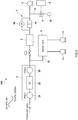
- the particle number counting device 100 is provided with an exhaust gas processing unit 2 that performs predetermined processing on exhaust gas diluted using a CVS or the like, a particle number counting unit 3 that counts a number of particles contained in exhaust gas that has passed through the exhaust gas processing unit 2, a differential pressure flow meter 4 that is provided downstream from the particle number counting unit 3, a suction pump 5 that is provided downstream from the differential pressure flow meter 4, a gas supply path 6 that is connected to a flow path between the differential pressure flow meter 4 and the suction pump 5, and supplies gas to a downstream side of the differential pressure flow meter 4, a flow rate adjustment unit 7 that is provided on the gas supply path 6, and adjusts a flow rate of the gas that is supplied to the downstream side of the differential pressure flow meter 4, and a control unit 8 that controls the flow rate adjustment unit 7.
- an exhaust gas processing unit 2 that performs predetermined processing on exhaust gas diluted using a CVS or the like
- a particle number counting unit 3 that counts a number of particles contained in exhaust gas that has passed through the exhaust gas processing
- the exhaust gas processing unit 2 is a volatile particle remover (VPR) that removes volatile particles that are formed by sulfuric acid mist and a soluble organic fraction (SOF) contained in the exhaust gas.
- VPR volatile particle remover
- This volatile particle remover 2 has a heat diluter 21, an evaporation tube 22, and a cold diluter 23.
- the exhaust gas is diluted, for example, by a factor of between 10 and 200 by the heat diluter 21 which has a predetermined first heating temperature (for example, 150 ⁇ 400 °C), and volatile particles that have already been formed are gasified by the evaporation tube 22 which has a second heating temperature (for example, 300 ⁇ 400 °C) provided further downstream.
- the exhaust gas is once again diluted, for example, by a factor of between 10 and 15 by the cold diluter 23, and the temperature thereof is lowered below a predetermined cooling temperature (for example, 35 °C).
- a predetermined cooling temperature for example, 35 °C
- the particle number counting unit 3 is a condensation particle counter (CPC) and operates by causing particulate matter to pass through a supersaturated alcohol (i.e., butanol or the like) atmosphere so that the diameter thereof grows to a large size, and then using laser light to count the particulate matter that is then expelled through a slit. If the introduction flow rate into this condensation particle counter becomes too fast, the growth of the particulate matter becomes insufficient. Because of this, it is desirable that the introduction flow rate be restricted to a predetermined range in which the particulate matter is still able to grow to a desired particle diameter.
- CPC condensation particle counter
- the differential pressure flow meter 4 measures the flow rate of exhaust gas flowing into the particle number counting unit 3, and is formed so as to measure the flow rate from a differential pressure between the pressure on an upstream side of an orifice 41 and the pressure on a downstream side thereof.
- the exhaust gas flow rate obtained by this differential pressure flow meter 4 is sent to the control unit 8.
- This differential pressure flow meter 4 has the orifice 41, which is a diaphragm mechanism that serves as a fluid resistance element, and also has a pressure sensor 42 that measures the differential pressure in the orifice 41.
- the suction pump 5 enables exhaust gas that has been processed by the exhaust gas processing unit 2 to flow into the particle number counting unit 3, and causes a predetermined differential pressure to be generated in the orifice 41 of the differential pressure flow meter 4.
- the suction pump 5 of the present embodiment suctions at a constant volume.
- the gas supply path 6 introduces gas between the differential pressure flow meter 4 and the suction pump 5. One end thereof is connected to the flow path between the differential pressure flow meter 4 and the suction pump 5, while another end thereof is connected to a buffer tank 9.
- the buffer tank 9 is provided on a gas discharge path 10 that is connected to the flow path between the exhaust gas processing unit 2 and the particle number counting unit 3, and an exhaust pump 11 is also provided on the gas discharge path 10.
- the buffer tank 9 reduces pulsations in the exhaust pump 11. Exhaust gas is introduced into the exhaust gas processing unit 2 via this structure.
- exhaust gas is introduced into the exhaust gas processing unit 2 by the suction pump 5.
- the flow rate adjustment unit 7 that is used to adjust the flow rate of the gas that is supplied between the differential pressure flow meter 4 and the suction pump 5 is provided on the gas supply path 6.
- This flow rate adjustment unit 7 is an electromagnetic valve. As a result of the valve opening thereof being controlled by the control unit 8, the flow rate of the gas supplied to the downstream side of the differential pressure flow meter 4 is adjusted so that the downstream-side pressure in the orifice 41 of the differential pressure flow meter 4 is also adjusted.
- the control unit 8 controls the valve opening of the flow rate adjustment unit (i.e., the electromagnetic valve) 7 in accordance with the differential pressure between the pressure on the upstream side of the orifice 41 and the pressure on the downstream side thereof as measured by the pressure sensor 42.
- the control unit 8 controls the flow rate adjustment unit 7 such that the differential pressure between the pressure on the upstream side of the orifice 41 and the pressure on the downstream side thereof falls within a predetermined range.
- the control unit 8 controls the flow rate adjustment unit 7 by acquiring a pressure measurement signal from this pressure sensor 42.
- relationship data showing a relationship between the differential pressure in the fluid resistance element and the valve opening is held in the control unit 8, and a control signal is output to the electromagnetic valve 7 based on the acquired pressure measurement signal.
- the aforementioned relationship data is data showing a relationship between the differential pressure (Pressure drop [kPa]) and the valve opening (Valve opening [%]).
- the flow rate adjustment unit 7 is provided on the gas supply path 6 that introduces a gas downstream from the differential pressure flow meter 4, by adjusting the flow rate of the gas that is supplied to the downstream side of the differential pressure flow meter 4 (i.e., of the orifice 41) in accordance with variations in the outside air pressure, it is possible to reduce variations in the flow rate flowing through the orifice 41. As a result, even if there are variations in the outside air pressure, it is still possible to perform accurate particle number counting.
- the control unit 8 controls the electromagnetic valve 7, which is serving as the flow rate adjustment unit, it is possible to automatically correct pressure variations, and to thereby improve the measurement accuracy when performing particle number counting.
- the flow rate of the exhaust gas introduced into the condensation particle counter 3 is adjusted by the suction pump 5, and the flow rate of the exhaust gas introduced into the exhaust gas processing unit 2 is principally adjusted by the exhaust pump 11, not only can a satisfactory flow rate be ensured for the exhaust gas flowing into the exhaust gas processing unit 2, but this flow rate can be adjusted to a more appropriate flow rate for enabling particulate matter to be properly grown in the condensation particle counter 3.
- the structure shown in FIG. 3 may also be employed for a particle number counting device.
- this particle number counting device 100 a structure is employed in which the other end of the gas supply path 6 is open to the atmosphere, and air is introduced via this other end.
- An anti-dust filter 12 such as, for example, a HEPA filter or the like is provided on the other end of the gas supply path 6.
- the flow rate of air that is supplied downstream from the differential pressure flow meter 4 is adjusted by the flow rate adjustment unit 7 provided on the gas supply path 6.
- two exhaust pumps 11 that are used to introduce exhaust gas into the exhaust gas processing unit 2 via the buffer tank 9 are provided, however, it is also possible to provide only a single exhaust pump 11.
- a structure that generates a pressure difference between the upstream side and the downstream side may be provided as the fluid resistance element and, for example, a Venturi type or capillary type of fluid resistance element may be used.
- a fixed flow meter or a differential pressure gauge or the like that employs these may also be used as the fluid resistance element.
- a pressure sensor that measures the outside air pressure outside the particle number counting device 100 it is also possible for a pressure sensor that measures the outside air pressure outside the particle number counting device 100 to be provided, and for the control unit 8 to control the flow rate adjustment unit 7 using an outside air pressure obtained by this pressure sensor.
- the pressure sensor that measures the outside air temperature may be the pressure sensor provided in the particle number counting device 100, or may be a pressure sensor that is provided independently of the particle number counting device 100.
- a structure is employed in which a buffer tank is provided in order to reduce pulsation, however, it is not essential that the buffer tank be provided.
- the suction pump 5 is used to not only introduce exhaust gas into the exhaust gas processing unit 2, but to also introduce diluted exhaust gas into the particle number counting unit 3.
Landscapes
- Chemical & Material Sciences (AREA)
- Combustion & Propulsion (AREA)
- Engineering & Computer Science (AREA)
- Physics & Mathematics (AREA)
- General Physics & Mathematics (AREA)
- Biochemistry (AREA)
- Analytical Chemistry (AREA)
- General Health & Medical Sciences (AREA)
- Life Sciences & Earth Sciences (AREA)
- Immunology (AREA)
- Pathology (AREA)
- Health & Medical Sciences (AREA)
- Dispersion Chemistry (AREA)
- Sampling And Sample Adjustment (AREA)
- Measuring Volume Flow (AREA)
Applications Claiming Priority (1)
| Application Number | Priority Date | Filing Date | Title |
|---|---|---|---|
| JP2018230563A JP7217624B2 (ja) | 2018-12-10 | 2018-12-10 | 粒子数計測装置及び粒子数計測方法 |
Publications (2)
| Publication Number | Publication Date |
|---|---|
| EP3667289A2 true EP3667289A2 (de) | 2020-06-17 |
| EP3667289A3 EP3667289A3 (de) | 2020-07-29 |
Family
ID=67809240
Family Applications (1)
| Application Number | Title | Priority Date | Filing Date |
|---|---|---|---|
| EP19194212.7A Withdrawn EP3667289A3 (de) | 2018-12-10 | 2019-08-28 | Vorrichtung und verfahren zur zählung der partikelzahl |
Country Status (3)
| Country | Link |
|---|---|
| US (1) | US11187641B2 (de) |
| EP (1) | EP3667289A3 (de) |
| JP (1) | JP7217624B2 (de) |
Families Citing this family (1)
| Publication number | Priority date | Publication date | Assignee | Title |
|---|---|---|---|---|
| FI129009B (en) * | 2020-02-05 | 2021-05-14 | Dekati Oy | Method and device for monitoring the density of aerosol particles |
Citations (1)
| Publication number | Priority date | Publication date | Assignee | Title |
|---|---|---|---|---|
| JP2012127773A (ja) | 2010-12-15 | 2012-07-05 | Shimadzu Corp | 粒子数計測装置 |
Family Cites Families (7)
| Publication number | Priority date | Publication date | Assignee | Title |
|---|---|---|---|---|
| GB1454602A (en) * | 1974-05-02 | 1976-11-03 | Jenkins A | Apparatus for checking the contents of closed containers |
| US6502450B1 (en) * | 1999-05-10 | 2003-01-07 | Rupprecht & Patashnik Company, Inc. | Single detector differential particulate mass monitor with intrinsic correction for volatilization losses |
| KR100614101B1 (ko) * | 2005-09-15 | 2006-08-22 | 한국과학기술연구원 | 입자 계수기 |
| JP5630894B2 (ja) * | 2010-02-05 | 2014-11-26 | 株式会社堀場製作所 | 粒子状物質計測装置 |
| JP2012154657A (ja) * | 2011-01-24 | 2012-08-16 | Shimadzu Corp | エアロゾル微粒子計測装置 |
| US9035242B2 (en) * | 2012-01-20 | 2015-05-19 | Tsi Incorporated | Instrument for sizing nanoparticles and a component therefor |
| US9708960B2 (en) * | 2013-05-08 | 2017-07-18 | Cummins Ip, Inc. | Exhaust aftertreatment system diagnostic and conditioning |
-
2018
- 2018-12-10 JP JP2018230563A patent/JP7217624B2/ja active Active
-
2019
- 2019-08-28 EP EP19194212.7A patent/EP3667289A3/de not_active Withdrawn
- 2019-09-09 US US16/564,931 patent/US11187641B2/en not_active Expired - Fee Related
Patent Citations (1)
| Publication number | Priority date | Publication date | Assignee | Title |
|---|---|---|---|---|
| JP2012127773A (ja) | 2010-12-15 | 2012-07-05 | Shimadzu Corp | 粒子数計測装置 |
Also Published As
| Publication number | Publication date |
|---|---|
| JP7217624B2 (ja) | 2023-02-03 |
| JP2020094810A (ja) | 2020-06-18 |
| US11187641B2 (en) | 2021-11-30 |
| US20200182767A1 (en) | 2020-06-11 |
| EP3667289A3 (de) | 2020-07-29 |
Similar Documents
| Publication | Publication Date | Title |
|---|---|---|
| CN101680821B (zh) | 废气取样稀释器及方法 | |
| KR101767271B1 (ko) | 배출가스 분석시스템 | |
| US8789406B2 (en) | Exhaust gas sampling and analysis system | |
| EP2102623B1 (de) | Festpartikel-zellsystem mit einem ventil zur ermöglichung einer verringerung des druckimpulses am partikelzähler, wenn die vakuumpumpe gestartet wird | |
| CN210862863U (zh) | 气体流量计检定装置 | |
| CN104364630A (zh) | 排气稀释装置 | |
| CN101571471A (zh) | 卷烟烟气气溶胶粒径分布的检测方法 | |
| JP6918927B2 (ja) | 受動型エアロゾル希釈器メカニズム | |
| CN114623904B (zh) | 一种气体流量计的校准装置和方法 | |
| US11187641B2 (en) | Particle number counting device and particle number counting method | |
| CN104122122B (zh) | 压力稳定采样装置 | |
| JP5476193B2 (ja) | 粒子数計測システム | |
| CN204064740U (zh) | 压力稳定采样装置 | |
| EP3803333B1 (de) | Kompensation des wirkungsgrades eines kondensationspartikels in der höhe | |
| EP2354779B1 (de) | Feststoffmessvorrichtung | |
| KR100726207B1 (ko) | 벽면 공기 유입식 컴팩트 미니 터널 희석장치 | |
| JP2007024730A (ja) | ラミナー型排気ガス流量計を用いた希釈排気サンプリング装置及び希釈排気サンプリング方法並びに加熱・冷却サージチューブ装置 | |
| CN201434815Y (zh) | 卷烟烟气气溶胶粒径分布实时检测装置 | |
| CN116072506A (zh) | 颗粒物进样装置、气溶胶质谱仪、单颗粒直径测量方法 | |
| JP3628126B2 (ja) | 抽出装置及び希釈装置 | |
| US20110266430A1 (en) | Gas inlet for a process mass spectrometer | |
| JP2005062056A (ja) | 排ガス流量計測装置およびこれを用いた排ガス計測システム | |
| WO2021066868A1 (en) | Mirror calibration of multiple flow-measurement devices | |
| JPH0640053B2 (ja) | 排気ガス中の粒子状物質の測定装置 |
Legal Events
| Date | Code | Title | Description |
|---|---|---|---|
| PUAI | Public reference made under article 153(3) epc to a published international application that has entered the european phase |
Free format text: ORIGINAL CODE: 0009012 |
|
| STAA | Information on the status of an ep patent application or granted ep patent |
Free format text: STATUS: THE APPLICATION HAS BEEN PUBLISHED |
|
| AK | Designated contracting states |
Kind code of ref document: A2 Designated state(s): AL AT BE BG CH CY CZ DE DK EE ES FI FR GB GR HR HU IE IS IT LI LT LU LV MC MK MT NL NO PL PT RO RS SE SI SK SM TR |
|
| AX | Request for extension of the european patent |
Extension state: BA ME |
|
| PUAL | Search report despatched |
Free format text: ORIGINAL CODE: 0009013 |
|
| AK | Designated contracting states |
Kind code of ref document: A3 Designated state(s): AL AT BE BG CH CY CZ DE DK EE ES FI FR GB GR HR HU IE IS IT LI LT LU LV MC MK MT NL NO PL PT RO RS SE SI SK SM TR |
|
| AX | Request for extension of the european patent |
Extension state: BA ME |
|
| RIC1 | Information provided on ipc code assigned before grant |
Ipc: G01N 15/06 20060101AFI20200622BHEP |
|
| STAA | Information on the status of an ep patent application or granted ep patent |
Free format text: STATUS: REQUEST FOR EXAMINATION WAS MADE |
|
| 17P | Request for examination filed |
Effective date: 20210126 |
|
| RBV | Designated contracting states (corrected) |
Designated state(s): AL AT BE BG CH CY CZ DE DK EE ES FI FR GB GR HR HU IE IS IT LI LT LU LV MC MK MT NL NO PL PT RO RS SE SI SK SM TR |
|
| STAA | Information on the status of an ep patent application or granted ep patent |
Free format text: STATUS: EXAMINATION IS IN PROGRESS |
|
| 17Q | First examination report despatched |
Effective date: 20220124 |
|
| STAA | Information on the status of an ep patent application or granted ep patent |
Free format text: STATUS: THE APPLICATION IS DEEMED TO BE WITHDRAWN |
|
| 18D | Application deemed to be withdrawn |
Effective date: 20230503 |